1
User’s
Manual
Models UM351 / UM331
Digital Indicator with Alarms
with Active Color PV Display
User’s Manual Setting/Explanation of Active Color PV Dislay
IM 05F01D12-04E
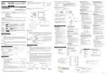
This manual describes the PV display color changing function “Active Color PV Display.”
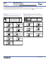
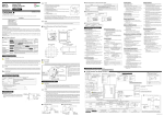
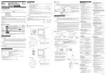
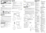
Carry out settings according to the following procedures after referring to “Functions of Active Color PV Display” on the back of this manual. Use “Parameter Map” of Parameters
key for more than 3 seconds. This brings
User’s Manual to understand the required parameters. If you cannot remember how to carry out an operation during setting, press the
you to the display (operating display) that appears at power-on. The UT321 is identical to the UM351/UM331 in items of front panel operation.
SET/ENT
■ Setting the PV display color changing function “Active Color
PV Display”
■ Setting the High Limit and Low limit for PV Color change
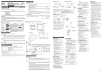
The following operating procedure describes an example of changing PV color
mode (factory-set default: Fixed in red mode) to Link to alarm 1 mode.
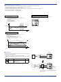
by linking to PV. Set High limit and Low limit for PV color change. Setting for both of
High limit and Low limit is required.
Parameter
Symbol
Name of
Parameter
Setting Range
PV color mode
0:
1:
2:
3:
4:
5:
6:
7:
(PCMD)
Initial Value
Fixed in green
Fixed in red
Link to alarm 1 (Alarm OFF:green, Alarm ON: red)
Link to alarm 1 (Alarm OFF:red, Alarm ON:green)
Link to alarm 1 and 2 (Alarm OFF:green, Alarm ON:red)
Link to alarm 1 and 2 (Alarm OFF:red, Alarm ON:green)
PV limit (Within PV range:green, Out of range:red)
PV limit (Within PV range:red, Out of range:green)
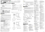
The following operating procedure describes an example of changing PV display color
Parameter Name of Parameter
Symbol
High limit
for PV color change
1
(PCCH)
Setting Range
power on).
(6) Press the
Low limit
for PV color change
(PCCL)
key several times to display the
menu “PCMD” (PV color mode).
SET/ENT
power-on).
PV
AL1
2
3
(4) Press the
key or
required setpoint.
Displays PV.
PV
Displays
parameter “PCMD”
Displays PV.
PV
When PCMD = 6 or 7:
PCCH:100.0 %, PCCL:0.0 %
When PCMC (PV color mode parameter)
= 6 or 7:
-100.0 to 100.0 % of PV input range.
(1) Bring the operating display into view (appears at
(1) Bring the operating display into view (appears at
Initial Value
AL1
2
3
key to display the
PV
4
AL1
2
3
4
Blinks during
change.
4
AL1
2
3
SET/ENT
4
SET/ENT
SET/ENT
SET/ENT
(2) Press the
key for more than 3 seconds to
call up the menu “OP.PA.”
SET/ENT
Displays
menu “OP.PA”
PV
(2) Press the
key for more than 3 seconds to
call up the menu “OP.PA.”
2
3
(5)
key or
key to display the
required setpoint. The figure below shows an
example of setting Link to alarm 1 mode.
Displays
menu “OP.PA”
PV
AL1
2
3
AL1
4
2
3
key once to display the menu
“STUP.”
Displays
menu “STUP”
PV
3
(8) Press the
key once to register the setpoint.
SET/ENT
If PCMD = 6, 7, 8 or 9,
also set the relating
paraemters PCCH
(High limit for PV color
change) and PCCL
(Low limit for PC color
change).
PV
4
AL1
2
3
4
SET/ENT
SET/ENT
key once to display the parameter
SET/ENT
“PWD.”
Displays
menu “PWD”
PV
AL1
2
4
SET/ENT
SET/ENT
(4) Press the
3
4
PCCL (Low limit for PV color change
parameter) that is displayed after this can be
SET/ENT
2
2
4
SET/ENT
AL1
key once to register the
SET/ENT
PV
Blinks
during change
AL1
(3) Press the
Press the
setpoint.
(7) Press the
PV
AL1
SET/ENT
3
(9) Press the
(3) Press the
key several times to display the
parameter “PCCH.”
SET/ENT
Displays parameter
“PCCH.”
PV
AL1
2
3
(6)
Press the
key for more than 3 seconds.
This returns you to the display shown at poweron (figure below).
SET/ENT
Displays PV.
PV
4
AL1
2
3
4
SET/ENT
SET/ENT
key for more than 3 seconds.
This returns you to the display shown at power-on
(figure blow).
SET/ENT
Displays PV.
PV
4
AL1
2
3
4
SET/ENT
SET/ENT
(5) Press the
key once to display the menu
SET/ENT
“FUNC.”
Displays
menu “FUNC”
PV
AL1
2
3
4
SET/ENT
IM 05F01D12-04E
3rd Edition : Sep. 30, 2004