1
PLFUR6ZLWFK7HFKQLFDO0DQXDO
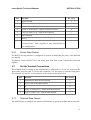
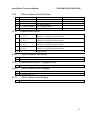
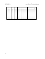
PIN
SIGNAL
,167$//$7,21
PC 9 way
1
Signal Ground
5
2
Transmitted data from MicroSwitch
3
3
Received data to MicroSwitch
2
4
Ready To Send (RTS) - output from MicroSwitch
8
5
Clear To Send (CTS) - input to MicroSwitch
7
6
Not connected
-
7
Reset 1
-
8
Reset 2
-
*Connect Pins 7 and 8 together to reset MicroSwitch to
user configuration.
2.6.1
Printer Data Format
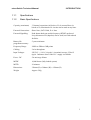
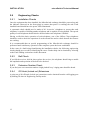
The RS232 call log interface is configured to operate at 9600 baud, no parity, 8-bit data and
one stop bit.
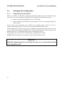
If hardware control (RTS/CTS) is not being used then Pins 4 and 5 should be connected
together.
2.7
Set Up Terminal Connections
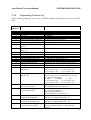
The terminal used for setting up the MicroSwitch is connected to a 9-way ‘D’ socket on the
front of the processor card. To access this connector, it is necessary to open the front panel.
The wiring to a 9-way PC serial connector is also shown in the table below.
PIN
2.7.1
SIGNAL
PC 9 way
2
Transmit data from the microSwitch
5
3
Receive data to the MicroSwitch
3
5
0V
2
7
Ready To Send (RTS) - output from MicroSwitch
8
8
Clear To Send (CTS) - input to MicroSwitch
7
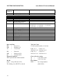
Terminal Data Format
The terminal port is configured to operate at 9600 baud, no parity, 8-bit data and one stop bit.
11