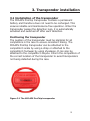
1
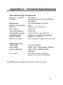
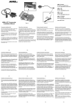
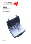
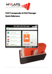
Contents
Contact information........................................... 2
1. introductioN...................................................... 3
2. Installation of the detection loop............ 4
2.1 Positioning the detection loop............................ 4
2.2 How to install correctly...................................... 6
1. Asphalt/ concrete, not permanent.................. 6
2. Ice.............................................................. 7
3. Snow........................................................... 7
2.3 Testing the detection loop.................................. 7
3. Installation of the Transponder................. 9
3.1 Positioning the transponder............................... 9
4. General remarks............................................... 10
Appendices
Appendix A - FAQs.......................................................... 11
Appendix B - Useful tools........................................... 14
Appendix C - Technical Specifications..................... 15
Appendix D - EC and FCC regulations......................... 16
Guarantees & Warranties........................................... 17
Figures
Figure 1.1 System overview............................................... 3
Figure 2.1 Detection loop installation overview.................... 5
Figure 3.1 MYLAPS ProChip Transponder............................. 9
1
Contact information
MYLAPS EMEA Office Haarlem
Haarlem
The Netherlands
Tel: +31 23 529 1893
E-mail: [email protected]
MYLAPS Americas Office
Atlanta
USA
Tel: +1 (678) 816 4000
E-mail:
[email protected]
MYLAPS Japan Office
Tokyo
Japan
Tel: +81 3 5275 4600
Email:
[email protected]
MYLAPS Asia Pacific Office
Sydney
Australia
Tel: +61 (0)2 9546 2606
Email:
[email protected] www.mylaps.com
All rights reserved
Copyright © 2007-2010 MYLAPS (formerly AMB i.t.)
This publication has been written with great care. However, the manufacturer
cannot be held responsible, either for any errors occurring in this publication
or for their consequences.
The sale of products, services of goods governed under this publication are
covered by MYLAPS’s standard Terms and Conditions of Sales and this product
manual is provided solely for informational purposes. This publication is to
be used for the standard model of the product of the type given on the cover
page.
MYLAPS
2
Manual: MYLAPS ProChip/01-2010
1: Introduction
The MYLAPS ProChip timing system, previously the ChipX
system, is designed for timing active sports including speed
and inline skating, skiing, cycling, running, triathlon and
more. The active detection loop continuously sends a signal
to activate the transponder when crossing the loop, and the
transponder then emits a signal which is picked up by the
loop. The detection loop is connected by wire to the MYLAPS
ProChip decoder. The decoder timestamps the received
transponder signals and sends this data to a connected
computer. The ProChip transponder can be attached to
the competitor’s ankle by using a strap or attached to the
competitor’s footwear by using shoelaces. It can also be
attached to the competitor’s bicycle.
Transponder
Detection loop
Power
Headphone
Computer
Decoder
Figure 1.1 System overview
3
2: Installation of the detection loop
Proper installation of the detection loop is essential in
achieving optimal system performance. Only approved
MYLAPS ProChip system loops should be used. The use of
any “homemade” loops can have an adverse effect on system
integrity. Please reference figure 2.1 for a diagram of proper
loop installation.
2.1 Positioning the detection loop
1. The ChipX system marks the passing time of a competitor
when the transponder is in the exact center of the loop
wires. Therefore the actual finish line should be located in
the center middle of the detection loop wires, or at a
point where the lead part of a competitor is at a constant
distance from the transponder and adjusted accordingly.
2. The loop wires are laid across the width of the course
in parallel to form a rectangle.
3. Make sure that the loop length is never less than 2m
(6,6ft) or greater than 12m (36ft).
4. Always cover 30cm (1ft) more than the track width on
each side to make sure that competitors never get closer
than 30cm (1ft) to either end of the loop.
5. Do not leave wires or coaxial cables rolled up or tangled
up as this may negatively affect system performance.
6. For competitor and spectator safety as well as to avoid
disconnections of the detection loops, always cover and
protect loop wires and coaxial cables.
7. All metal in the environment of the loop may decrease
the activation signal and transponder detection height
significantly. Avoid installation above or near metal,
including reinforced concrete.
8. Even though the coaxial cable to the loop is double
shielded it is still possible for transponder signals to be
received via the coaxial cable. Therefore keep the coaxial
4
cable at least 1m (3ft) away from areas where participants
with transponders might pass.
Example: In cycling events the competitor finishes when the leading edge of the
bicycle’s front tire is right above the finish line. For correct installation, first measure the
distance between the transponders and the leading edge of the front tire. Then position
the middle of the loop wires in front of the finish line, at the exact same distance. This
will ensure that the transponder is accurately scored at the same instant the leading
edge of the front tire is right above the finish line.
max.
transponder height
90 cm (3 ft)
AMB ProChip Transponder
sponder
FINISH LINE
End Box
30 cm
60 cm or see
decoder manual
max. 12 m (36ft)
Center of Loop Wires
30 cm
Connection box
Coaxial cable
Figure 2.1 Detection loop installation overview
5
2.2 How to install correctly
The ChipX detection loop is supplied with connectors. Do
not use any other connectors than the ones supplied. The
connectors are intended to be used for short term installations
(up to 2 days). For longer term installation, solder the loop
wires as described below.
Note:
The ProChip loop is not compatible with any other MYLAPS
system loops. If you have a setup with multiple loops, keep
the loops at least 10m (30ft) apart from each other. Be aware
that even when the loops have some distance from each
other, the transponder signal may transfer from one loop to
another through surrounding metal. If this happens, you will
receive the tranponder signals on both loops simultaneously.
The detection loop is sensitive to interference that can be
created by nearby cabling or picked up by nearby metal
structures. When possible, keep other cables at least 5m
(15ft) away. Also, make sure athletes on other parts of the
track will not get closer than 5m (15ft) to the detection loop
to avoid false inputs.
The type of loop installation that is most suitable depends on
the ground surface. Please follow the instructions according to
the surface your loop in installed on.
1. Asphalt/concrete, not permanent (tape)
Adhesive tape can be used to affix the loop wires to the
course. We recommend industrial strength Polyken #203, Tesa
4651 or similar tape, 10cm (4inch) wide. Lay the tape over
each loop wire, placing the wire in the center of the strip of
tape and secure the tape to the road.
6
2. Ice
Cut slots 2cm (1inch) deep in the ice. Put the loop wires in the
slots and fill them with snow/water at least 12 hours prior to
the start of the event to allow the slot to re-freeze.
3. Snow
Cut slots in the snow, approximately 20cm (8inch) deep. Try
to keep the slots as horizontal as possible. Put the loop wires
in the slots and fill them with snow.
Note:
Make absolutely certain that the loop is installed securely to
avoid possible injury to competitors and spectators from loose
loop wires.
2.3 Testing the detection loop
Once the loop has been installed, it should be tested to
ensure that it is functioning correctly. Repeat the same
procedure before each event. You can determine if your loop
is functioning correctly by performing the following tests:
1. Connect the detection loop to the decoder and then check
for any background noise (visible on the display, see your
decoder manual). The background noise level is usually
between 0 and 40 points. A higher value may indicate a
bad loop installation or interference by other electrical
equipment in the area. Try switching off any suspected
equipment or removing nearby metal objects and check
for improvements.
2. Check the signal strength of the transponders as they are
picked up by the system during a test (also see paragraph
3.1 Installation of the Transponder). A good loop will
yield consistent transponder signal strength of at least
100 points with a hit rate of at least 10 hits. The hit rate
may vary depending on the speed of the transponder
passings, as well as the height of the transponder as it
passes over the loop (slower and lower passings may yield
higher hit counts). Performance of the system depends
7
on the difference between the received signal strength
of the transponder and the background noise level.
Usually, if the transponder strength is more than 60 points
higher than the background noise, the detection of the
transponder will be reliable.
3. Check the detection height. The detection height will
vary depending on correct installation of the
detection loop and the presence of metal items in the
vicinity of the loop and coaxial calbe. Metal in the vicinity
of the coaxial cable and loop may weaken the activation
field and consequently decrease the detection height.
Examples are reinforced concrete floors or ice rink
floors with cooling installations. To measure detection
height, connect headphones or a speaker to the decoder.
Stand in the middle of the detection loop and hold up a
ProChip transponder as high as possible. Slowly move the
transponder toward the ground. Determine the detection
height by listening for the beep.
Note:
In case of reinforced concrete floor or other metal below, the
transponders may need to be placed a maximum of 30cm
(1ft) above the track.
8
3. Transponder installation
3.1 Installation of the transponder
The MYLAPS ProChip transponder contains a permanent
battery and therefore does not need to be recharged. This
ensures reliable and maintenance-free operation. When the
transponder passes the detection loop, it is automatically
activated and switched off after each detection.
Positioning the transponder
The position of the transponder must be identical for all
competitors in the race to ensure consistent timing. The
MYLAPS ProChip transponder can be attached to the
competitor’s ankle by using a strap or attached to the
competitor’s footwear by using shoelaces. It can also be
attached to the competitor’s bicycle. Inform the competitors of
the correct location of the transponder to avoid transponders
not being detected during the race.
Figure 3.1 The MYLAPS ProChip transponder
9
4 : General Remarks
Keep transponders away from cabling or electrical equipment
to maximize transponder and battery life. Keep in mind that
wires and metal objects transfer transponder signals. This may
cause the system to detect transponders even at a significant
distance. Keep extra transponders away from the loop and
decoder to avoid unwanted passings during an event.
For optimal performance at low temperatures, it is advisable
to keep the transponders as warm as possible during a
race (e.g. keep it under clothing). Preferred storage of the
equipment is at room temperature.
10
Appendix A : FAQs
A1: Transponder not being detected
A few of the transponders are not being detected.
If this is the case, the problem is most likely related to the
transponder or the positioning of the transponder.
- Check the position of the transponder, refer to
paragraph 3.1.
None of the transponders are being detected.
If this is the case, the problem is most likely related to the
detection loop, decoder, timing computer or cabling. Please
take the following steps:
- Check if a beep is heard in the headphone, or if the
loop in the decoder display changes to black during
a transponder passing. If this is working, and the
computer screen appears blank, check the cabling
between the decoder and the computer.
- Check the coaxial cable by measuring the resistance
(with multimeter) between the center pin and the
outside of the BNC connector. The reading should be
approximately 150 kOhm after 30 seconds. If not, the
coaxial must be replaced.
- Check the loop wire measuring the resistance between the loop wires in the track. The reading should be approximately 220 Ohm. If this is not the case, the loop must be replaced.
A2: Noise levels
What if my background noise is higher than 40 points?
An increased background noise is an indication of a higher
interference level picked up by the system. Every five seconds,
a background noise measurement is performed by the
11
decoder and sent to the computer. The noise level should be
as low as possible, but as long as the received signal from
the transponders is 60 points higher then the noise level,
detection will be reliable. If the noise level is higher than 70
there is most likely something wrong with the installation.
Possible causes of high background noise levels:
-
When the detection loop is damaged, a fluctuation in noise level will be noticeable, especially in wet conditions. If this is the case, check the loop wire and coaxial for cuts or breakage.
-Electrical equipment too close (<3 m) to the loop or coaxial cable.
-
Use of a generator with a poor ground connection.
-
Use of DC/AC converter for AC power.
-
Poor connections between the detection loop and the coaxial cable.
-
BNC connector incorrectly fitted to the coaxial cable.
-
Poor ground connection of the AC power. If this is the case, ground the decoder by connecting the outside of the BNC connectors on the decoder to a piece of metal (copper rod or tube) that is in a fixed connection with the ground.
Troubleshooting Tips for High Noise Levels
1. Be sure to keep ALL non-MYLAPS wires (including power wires) at least 30 ft. away from the loop.
2. Try using a different power supply.
3. Try moving the existing loop around and see if the noise level drops. There may be power cables underneath the ground that could cause higher noise levels.
4. Try moving the loop.
5. Try using a new loop wire.
6.
Try using another MYLAPS decoder
12
A3: Signal strength
What if the received signal strength is below 100
points?
-
If the signal strength is lower that 100 points, please check the position of the transponder.
-
If the signal strength is fluctuating heavily in combination with high noise levels, check the quality of the loop installation and coaxial cables.
If you have any questions or remarks please contact MYLAPS
Sports Timing. You can find our contact details on page 2 of
this manual.
13
Appendix B: Usefool tools
Useful Tools
Resistance meter (Range at least: 1 Ohm - 1 Mega Ohm)
Wire cutter/stripper
BNC Crimper
(Butane) Soldering gun
Blade knife
Coax stripper
Ice pick
Screw driver (normal and Phillips)
Shrinksleeve
Useful Spare Parts
BNC couplers (3 pieces)
Thick BNC connectors (5 pieces)
Spare loops (6, 9, or 12 m)
Additional Tools for new loop installations
Polyken #203 4 inch-wide tape/ Tesa 4651
Chalk line
Caulk gun
Please contact MYLAPS Sports Timing if you would like to
receive detailed specifications on any of the above items.
14
Appendix C: Technical Specifications
MYLAPS ProChip Transponder
Numbers available
: unlimited
Fixation
: several options like ankle strap or shoe lace
Dimensions
: 37 mm diameter x 13 mm
Weight transponder : 16 g
Housing
: Water- and shockproof
Max. speed
: 75 km/h
Timing Resolution
: 0.004 sec
Temperature range : -20 to 50 °C (-4 to 122 °F)
Operating time
: approx. 120,000 loop passings
Signal transfer
: magnetic induction
Detection Height
: max. detection height 90 cm ( 3 ft)
Detection Loop
Track width
Loop width
Coax to decoder
Loop wire
: 2-12m (10-36ft)
: 60cm (2ft) *see decoder manual
: max. 100m (330ft) double
shielded
: d=3 mm (1/8 in), tinned copper, 0.75 mm² (18 AWG)
Specifications are subject to change without notice.
15
Appendix D: CE and FCC regulations
CE information:
This device complies with the EMC directive 89/336/EEC. A
copy of the declaration of conformity can be obtained at:
MYLAPS Sports Timing
Zuiderhoutlaan 4
2012 PJ Haarlem
The Netherlands
FCC information:
This equipment complies with part 15 of the FCC rules.
Operation is subject to the following two conditions: (1) This
equipment may not cause harmful interference, and (2) this
equipment must accept any interference received, including
interference that may cause undesired operation.
16
Guarantees & Warranties
MYLAPS, formerly AMB, warrants that, for a period of three (3) years from the date of
shipping the decoders and the MYLAPS MX Rechargeable Power (AMBmx), MYLAPS RC
DP (AMBrc DP), MYLAPS KART DP (TranX160 DP), MYLAPS Kart Rechargeable Power
(TranX160), MYLAPS Car/Bike DP (TranX260 DP), MYLAPS Car/Bike Rechargeable Power
(TranX260), MYLAPS Car/Bike Pro (TranX Pro) transponders covered by this warranty
with defects, as determined solely by MYLAPS, caused by faulty materials, workmanship
or design will be repaired or replaced, unless such defects were the result of any of the
following: shipping; improper installation, maintenance or use; abnormal conditions of
operation; attempted modification or repair by the customer or any third party; use of
the goods in combination with other items; or an act of God. If repair or replacement of
the goods is not possible or economical for MYLAPS, MYLAPS may, at its option, refund
the purchase price of the goods or deliver replacement goods at its sole discretion.
MYLAPS’s liability shall be strictly limited to replacing, repairing or issuing credits at its
option.
MYLAPS warrants that, for a period of two (2) years from the date of shipping the
ProChip, MYLAPS Kart Fixed Power (TranX140) and the MYLAPS RC Rechargeable
Power (AMBrc) transponders covered by this warranty with defects, as determined
solely by MYLAPS, caused by faulty materials, workmanship or design will be repaired
or replaced, unless such defects were the result of any of the following: shipping;
improper installation, maintenance or use; abnormal conditions of operation; attempted
modification or repair by the customer or any third party; use of the goods in
combination with other items; or an act of God. If repair or replacement of the goods is
not possible or economical for MYLAPS, MYLAPS may, at its option, refund the purchase
price of the goods or deliver replacement goods at its sole discretion. MYLAPS’s liability
shall be strictly limited to replacing, repairing or issuing credits at its option.
MYLAPS warrants that, for a period of one (1) year from the date of shipping the
MYLAPS Onboard Display kit (TnetX Display Kit) covered by this warranty with defects,
as determined solely by MYLAPS, caused by faulty materials, workmanship or design
will be repaired or replaced, unless such defects were the result of any of the following:
shipping; improper installation, maintenance or use; abnormal conditions of operation;
attempted modification or repair by the customer or any third party; use of the goods in
combination with other items; or an act of God. If repair or replacement of the goods is
not possible or economical for MYLAPS, MYLAPS may, at its option, refund the purchase
price of the goods or deliver replacement goods at its sole discretion. MYLAPS’s liability
shall be strictly limited to replacing, repairing or issuing credits at its option.
MYLAPS warrants that, for a period of one (1) year from the date of shipping, all other
goods covered by this warranty with defects, as determined solely by MYLAPS, caused by
faulty materials, workmanship or design will be repaired or replaced, unless such defects
were the result of any of the following: shipping; improper installation, maintenance or use;
abnormal conditions of operation; attempted modification or repair by the customer or any
third party; use of the goods in combination with other items; or an act of God. If repair or
replacement of the goods is not possible or economical for MYLAPS, MYLAPS may, at its option,
refund the purchase price of the goods or deliver replacement goods at its sole discretion.
MYLAPS’s liability shall be strictly limited to replacing, repairing or issuing credits at its option.
If the requirements set forth above and described under Remedies and Damages are not
complied with, our warranty/guarantee shall not apply and we shall be discharged from all
liability arising from the supply of defective goods.
17
EXCEPT AS EXPRESSLY PROVIDED IN THIS SECTION, MYLAPS MAKES NO
REPRESENTATIONS OR WARRANTIES OF ANY KIND, NATURE OR DESCRIPTION, EXPRESS
OR IMPLIED, INCLUDING WITHOUT LIMITATION, ANY WARRANTY OR MERCHANTABILITY,
FITNESS OF THE GOODS FOR ANY PARTICULAR PURPOSE, OR NONINFRINGEMENT, AND
MYLAPS HEREBY DISCLAIMS THE SAME.
Remedies and Damages
1. MYLAPS shall not incur any liability under the above warranty unless:
i) MYLAPS is promptly notified in writing upon discovery by the customer that such
goods do not conform to the warranty, and the appropriate invoice number and
date of purchase information is supplied;
ii) The alleged defective goods are returned to MYLAPS carriage pre-paid;
iii) Examination by MYLAPS of goods shall confirm that the alleged defect exists and
has not been caused by unauthorized use (including, without limitation, the use of
an AMB decoder with non-MYLAPS hardware) misuse, neglect, method of storage,
faulty installation, handling, or by alteration or accident; and
iv) With respect to MYLAPS decoders, customer has upgraded the firmware in its
decoder within one month after MYLAPS has offered to provide customer with such
upgraded firmware.
2. The customer acknowledges that the goods may include certain firmware imbedded
therein. MYLAPS hereby grants a license to customer to use the imbedded firmware
in an MYLAPS decoder, but only to the extent the decoder is used in connection with
MYLAPS hardware. MYLAPS shall have the right to terminate the license immediately
upon written notice to customer in case MYLAPS has a reasonable belief that
customer at any time has used the MYLAPS decoder in connection with non-AMB
hardware. Further, customer may not copy, compile, reverse compile, disassemble,
translate, analyze, reverse engineer or attempt to reverse engineer the firmware,
except as permitted by applicable law.
3. In addition, customer grants MYLAPS the option to repurchase any MYLAPS decoder
if MYLAPS has a reasonable belief that customer has used the MYLAPS decoder
in connection with non-MYLAPS hardware. The repurchase price shall be the fair
market value on the date MYLAPS provides notice to customer that it intends to
repurchase the decoder.
The above mentioned warranty/guarantee is irrespective of any rights granted to the
buyer of MYLAPS equipment manufactured or sold by MYLAPS based on the laws of the
Netherlands. Any correspondence regarding the above mentioned guarantee must be
addressed to MYLAPS:
MYLAPS EMEA OFFICE HAARLEM
Zuiderhoutlaan 4
2012 PJ HAARLEM
THE NETHERLANDS
E-mail: [email protected]
Fax: +31 23 529 0156
18