1
Drive Technology \ Drive Automation \ System Integration \ Services
Manual
IPOSplus® Positioning and Sequence Control System
Edition 11/2009
11645415 / EN
SEW-EURODRIVE—Driving the world
Contents
Contents
1
2
General Information .......................................................................................... 14
1.1
Structure of the safety notes ..................................................................... 14
1.2
Liability for defects .................................................................................... 15
1.3
Exclusion of liability................................................................................... 15
1.4
Copyright................................................................................................... 15
Safety Notes ...................................................................................................... 16
2.1
3
General information .................................................................................. 16
2.2
Designated use ......................................................................................... 17
2.3
Target group ............................................................................................. 17
2.4
Programming errors .................................................................................. 17
System Description........................................................................................... 18
3.1
Introduction ............................................................................................... 18
3.1.1
3.1.2
IPOS
3.3
Controlling IPOSplus® units ....................................................................... 22
3.4
3.5
3.6
5
Manual – IPOSplus®
Creating programs ..................................................................... 19
plus®
3.2
3.3.1
4
Scope of this documentation ..................................................... 18
– features ................................................................................. 19
Active control signal source ....................................................... 22
Technology options / application modules ................................................ 22
3.4.1
Technology options.................................................................... 22
3.4.2
Application modules................................................................... 23
Technical data........................................................................................... 25
3.5.1
MOVIDRIVE® B ......................................................................... 25
3.5.2
MOVITRAC® B .......................................................................... 25
3.5.3
MQx ........................................................................................... 26
Reference documents............................................................................... 27
3.6.1
General manuals ....................................................................... 27
3.6.2
Manuals for serial interfaces/fieldbuses .................................... 27
3.6.3
Manuals for synchronized axis movements............................... 27
3.6.4
Manuals for application modules ............................................... 27
3.6.5
Manuals for the MQx fieldbus interfaces ................................... 27
IPOS Variables................................................................................................... 28
4.1
Introduction ............................................................................................... 28
4.2
Overview of the system variables ............................................................. 29
Task Management and Interrupts .................................................................... 40
5.1
Introduction ............................................................................................... 40
5.2
Task management for MOVIDRIVE® A and B .......................................... 40
5.3
Tasks for MOVIDRIVE® A......................................................................... 43
5.4
Tasks for MOVIDRIVE® B......................................................................... 43
5.4.1
Processing time for task 1 / task 2............................................. 43
5.4.2
Task 3 ........................................................................................ 44
5.4.3
Implementation information ....................................................... 44
5.4.4
Example..................................................................................... 45
3
Contents
5.5
Interrupts................................................................................................... 45
5.5.1
5.6
5.7
6
5.6.1
Interrupt activation ..................................................................... 46
5.6.2
Error interrupt............................................................................. 46
5.6.3
Touch probe DI02 interrupt........................................................ 47
5.6.4
Timer0 interrupt ......................................................................... 48
Variable interrupts with MOVIDRIVE® B................................................... 49
5.7.1
Calling up the variable interrupt ................................................. 49
5.7.2
IPOS access to the internal interrupt control ............................. 50
Position Detection and Positioning................................................................. 53
6.1
Encoder evaluation ................................................................................... 53
6.2
Motor encoder (X15) ................................................................................. 54
6.3
Encoder combinations .............................................................................. 54
6.4
External encoder (X14) ............................................................................. 57
6.5
6.6
6.7
4
Example..................................................................................... 46
Interrupts for MOVIDRIVE® A and B......................................................... 46
6.4.1
Positioning on external encoder (X14)....................................... 57
6.4.2
Slip compensation with external encoder .................................. 57
SSI absolute encoder (DIP) ...................................................................... 60
6.5.1
Startup ....................................................................................... 60
6.5.2
1. Select encoder type P950...................................................... 60
6.5.3
2. Set direction of rotation of the motor P35_ ............................ 61
6.5.4
3. Set counting direction P951 for the SSI absolute encoder .... 61
6.5.5
4. Set encoder scaling P955...................................................... 61
6.5.6
5. Set position offset P953......................................................... 61
6.5.7
6. Set Zero offset P954.............................................................. 62
6.5.8
7. Set encoder factors P942 and P943...................................... 62
6.5.9
8. Set P941 actual position source ............................................ 62
Referencing............................................................................................... 63
6.6.1
Type 0: Reference travel to zero pulse...................................... 67
6.6.2
Type 1: CCW end of the reference cam .................................... 67
6.6.3
Type 2: CW end of the reference cam....................................... 68
6.6.4
Type 3: CW limit switch ............................................................. 69
6.6.5
Type 4: CCW limit switch........................................................... 69
6.6.6
Type 5: No reference travel ....................................................... 70
6.6.7
Type 6: Reference cam flush with CW limit switch .................... 70
6.6.8
Type 7: Reference cam flush with CCW limit switch ................. 71
6.6.9
Type 8: Without enable.............................................................. 72
Modulo function......................................................................................... 73
6.7.1
Introduction ................................................................................ 73
6.7.2
Operating principle .................................................................... 74
6.7.3
Travel strategies ........................................................................ 77
6.7.4
Project planning ......................................................................... 80
6.7.5
Project planning examples......................................................... 80
6.7.6
Frequently asked questions....................................................... 83
Manual – IPOSplus®
Contents
6.8
7
8
Cam controllers......................................................................................... 84
6.8.1
Standard cam controller............................................................. 85
6.8.2
Expanded cam controller ........................................................... 89
Position Detection via Binary Inputs............................................................... 96
7.1
Types of built-in encoders......................................................................... 96
7.2
Principle of the position detection ............................................................. 96
7.3
Position detection with MOVIDRIVE® B.................................................... 97
7.4
Position detection with MOVITRAC® B..................................................... 98
7.5
Position detection with MQx...................................................................... 99
IPOS
7.5.1
Proximity sensor evaluation....................................................... 99
7.5.2
DI0 and DI1 terminal assignments............................................. 99
7.5.3
Position detection with built-in encoder ................................... 100
7.5.4
Encoder monitoring.................................................................. 100
7.5.5
Storing the actual position ....................................................... 100
7.5.6
Counter .................................................................................... 101
7.5.7
Connecting the built-in encoders ............................................. 101
plus®
and Fieldbus ................................................................................... 102
8.1
Introduction ............................................................................................. 102
8.2
Binary inputs and outputs ....................................................................... 103
8.3
Cyclical process data .............................................................................. 103
8.2.1
8.3.1
Cyclical preset process data.................................................... 103
8.3.2
Cyclical user-specific process data.......................................... 104
8.4
Acyclical communication ......................................................................... 105
8.5
Special features of communication via SBus .......................................... 105
8.6
Special features of communication via RS-485 ...................................... 106
8.7
9
IPOS
Fieldbus control words and fieldbus status words .................................. 106
plus®
and Synchronized Motion ............................................................. 107
9.1
Introduction ............................................................................................. 107
9.2
Speed synchronization via master/slave function ................................... 107
9.3
9.4
Synchronous operation with a DRS option card ..................................... 107
9.3.1
Activating and deactivating the free running function .............. 108
9.3.2
Setting the zero point for DRS11B........................................... 109
9.3.3
Activating and deactivating the offset function......................... 111
9.3.4
Switching between positioning and synchronous operation .... 113
Synchronous operation with technology option "Internal synchronous
operation"................................................................................................ 115
9.4.1
9.5
Requirements .......................................................................... 115
Synchronous operation with technology option "Cam" ........................... 116
9.5.1
10
Fieldbus interface, DIO and DIP .............................................. 103
Requirements .......................................................................... 117
IPOSplus® for MOVITRAC® B – Characteristics............................................. 118
10.1 Requirements.......................................................................................... 118
10.2 Functionality ............................................................................................ 119
11
IPOSplus® for MQx – Characteristics.............................................................. 120
11.1 Introduction ............................................................................................. 120
Manual – IPOSplus®
5
Contents
11.2 Starting the programming tool................................................................. 121
11.3 Sequence control system........................................................................ 121
11.4 Digital inputs and outputs........................................................................ 121
11.5 Values of the DIAG11 variable for the error IPOS ILLOP ....................... 122
12
P9xx IPOS Parameters.................................................................................... 123
12.1 P90x IPOS reference travel .................................................................... 123
12.1.1
P900 Reference offset ............................................................. 123
12.1.2
P901 Reference speed 1 ......................................................... 124
12.1.3
P902 Reference speed 2 ......................................................... 124
12.1.4
P903 Reference travel type ..................................................... 124
12.1.5
P904 Reference travel to zero pulse ....................................... 126
12.1.6
P905 Hiperface offset X15....................................................... 126
12.1.7
P906 Cam distance ................................................................. 126
12.2 P91x IPOSplus® parameters.................................................................... 127
12.2.1
P910 Gain X controller............................................................. 127
12.2.2
P911/912 Positioning ramp 1/2................................................ 127
12.2.3
P913/P914 Travel speed CW/CCW......................................... 127
12.2.4
P915 Velocity precontrol.......................................................... 127
12.2.5
P916 Ramp type ...................................................................... 128
12.2.6
P917 Ramp mode.................................................................... 130
12.2.7
P918 Bus setpoint source........................................................ 130
12.3 P92x IPOS monitoring ............................................................................ 131
12.3.1
P920/P921 SW limit switch CW/CCW ..................................... 131
12.3.2
P922 Position window.............................................................. 131
12.3.3
P923 Lag error window............................................................ 131
12.3.4
P924 Positioning interruption detection ................................... 131
12.4 P93x IPOSplus® special functions ........................................................... 132
12.4.1
P930 Override.......................................................................... 132
12.4.2
P931 IPOS CTRL.W Task 1 .................................................... 132
12.4.3
P932 IPOS CTRL.W Task 2 .................................................... 132
12.4.4
P933 Jerk time......................................................................... 132
12.4.5
P938 Speed task 1 .................................................................. 132
12.4.6
P939 Speed task 2 .................................................................. 133
12.5 P94x IPOSplus® encoder......................................................................... 134
6
12.5.1
P940 IPOS variable edit .......................................................... 134
12.5.2
P941 Actual position source .................................................... 134
12.5.3
P942/P943 Encoder factor numerator/denominator ................ 134
12.5.4
P944 Encoder scaling ext. encoder ......................................... 135
12.5.5
P945 Synchronous encoder type (X14)................................... 135
12.5.6
P945 Synchronous encoder counting direction (X14) ............. 136
12.5.7
P947 Hiperface offset X14....................................................... 136
12.5.8
P948 Automatic encoder replacement detection ..................... 137
Manual – IPOSplus®
Contents
12.6 P95x absolute encoder (SSI) .................................................................. 138
12.6.1
P950 Encoder type .................................................................. 138
12.6.2
P951 Counting direction .......................................................... 138
12.6.3
P952 Cycle frequency.............................................................. 139
12.6.4
P953 Position offset................................................................. 139
12.6.5
P954 Zero offset ...................................................................... 139
12.6.6
P955 Encoder scaling.............................................................. 139
12.6.7
P956 CAN encoder baud rate.................................................. 139
12.7 P96x IPOSplus® modulo function ............................................................ 140
12.7.1
P960 Modulo function .............................................................. 140
12.7.2
P961 Modulo numerator .......................................................... 140
12.7.3
P962 Modulo denominator....................................................... 140
12.7.4
P963 Modulo encoder resolution ............................................. 140
12.8 P97x IPOS synchronization .................................................................... 141
13
12.8.1
P970 DPRAM synchronization ................................................ 141
12.8.2
P971 Synchronization phase ................................................... 141
Compiler – Editor ............................................................................................ 142
13.1 Technical features................................................................................... 142
13.2 First steps ............................................................................................... 143
13.2.1
Step 1: Starting IPOSplus® Compiler with MOVITOOLS®
MotionStudio............................................................................ 143
13.2.2
Step 2: Creating a new project ................................................ 145
13.2.3
Step 3: The first IPOSplus® program ........................................ 148
13.2.4
Step 4: Compiling and starting the IPOSplus® program ........... 151
13.3 Settings for the IPOSplus® Compiler ....................................................... 154
13.4 Search function ....................................................................................... 157
13.5 Creating a new project ............................................................................ 158
13.5.1
Project properties..................................................................... 158
13.5.2
Defining the program structure ................................................ 159
13.6 Saving a project ...................................................................................... 161
13.7 Setting up a project management structure ............................................ 162
13.8 Opening a project.................................................................................... 164
13.9 Handling projects with MOVIDRIVE® B .................................................. 164
13.9.1
Saving a project in the inverter ................................................ 164
13.9.2
Loading a project from the inverter .......................................... 165
13.9.3
Calling up a project from the inverter....................................... 165
13.10 Compiling a project ................................................................................. 166
13.11 Compiling and downloading .................................................................... 167
13.12 Starting a program .................................................................................. 167
13.13 Stopping a program ................................................................................ 167
13.14 Comparison with unit .............................................................................. 167
13.15 Debugger ................................................................................................ 168
13.16 Variable window...................................................................................... 169
13.17 Program information ............................................................................... 171
13.18 Entering instructions ............................................................................... 172
13.19 Comments............................................................................................... 173
Manual – IPOSplus®
7
Contents
13.20 Overview of the icons.............................................................................. 174
14
Compiler – Programming ............................................................................... 175
14.1 Preprocessor........................................................................................... 176
14.2 Preprocessor statements ........................................................................ 176
14.3 #include................................................................................................... 178
14.4 Include folders......................................................................................... 179
14.5 #define .................................................................................................... 179
14.6 #undef ..................................................................................................... 180
14.7 #declare .................................................................................................. 181
14.8 SEW standard structures ........................................................................ 182
14.9 User-defined structures........................................................................... 184
14.10 long ......................................................................................................... 186
14.11 initial long ................................................................................................ 186
14.12 #pragma .................................................................................................. 187
14.13 Explanation of const.h and io.h / constb.h and iob.h .............................. 188
14.14 Identifiers ................................................................................................ 190
14.15 Constants................................................................................................ 190
14.16 IPOSplus® variables in the compiler ........................................................ 191
14.16.1 Example................................................................................... 191
14.17 Declaration of global variables................................................................ 191
14.18 Indirect addressing – pointer................................................................... 192
14.19 numof().................................................................................................... 193
15
Compiler – Operators ..................................................................................... 194
15.1 Order of priority of operators................................................................... 194
15.2 Unary operators ...................................................................................... 195
15.3 Binary operators...................................................................................... 196
15.3.1
Example................................................................................... 196
15.4 Ternary operators ................................................................................... 196
15.4.1
16
Example................................................................................... 196
Compiler – Constructions .............................................................................. 197
16.1 if...else..................................................................................................... 197
16.1.1
Syntax...................................................................................... 197
16.2 for............................................................................................................ 198
16.2.1
Syntax...................................................................................... 198
16.3 while........................................................................................................ 199
16.3.1
Syntax...................................................................................... 199
16.4 do...while................................................................................................. 200
16.4.1
Syntax...................................................................................... 200
16.5 switch...case...default.............................................................................. 202
16.5.1
Syntax...................................................................................... 202
16.6 return....................................................................................................... 203
8
Manual – IPOSplus®
Contents
17
Compiler – Functions ..................................................................................... 204
17.1 User-defined functions ............................................................................ 204
17.2 Overview of commands for standard functions ....................................... 205
17.2.1
Standard bit functions .............................................................. 205
17.2.2
Standard communication functions.......................................... 206
17.2.3
Standard positioning functions................................................. 206
17.2.4
Standard program functions .................................................... 206
17.2.5
Standard setting functions ....................................................... 207
17.2.6
Special standard unit functions................................................ 207
17.3 Standard functions .................................................................................. 208
17.3.1
_AxisStop................................................................................. 208
17.3.2
_BitClear .................................................................................. 209
17.3.3
_BitMove.................................................................................. 209
17.3.4
_BitMoveNeg ........................................................................... 209
17.3.5
_BitSet ..................................................................................... 210
17.3.6
_Copy ...................................................................................... 210
17.3.7
_FaultReaction......................................................................... 210
17.3.8
_GetSys ................................................................................... 211
17.3.9
_Go0 ........................................................................................ 217
17.3.10 _GoAbs.................................................................................... 218
17.3.11 _GoRel..................................................................................... 219
17.3.12 _InputCall................................................................................. 220
17.3.13 _Memorize ............................................................................... 221
17.3.14 _MoviLink................................................................................. 222
17.3.15 _MovCommDef ....................................................................... 227
17.3.16 _MovCommOn......................................................................... 229
17.3.17 _Nop ........................................................................................ 229
17.3.18 _SBusCommDef ...................................................................... 230
17.3.19 _SBusCommOn....................................................................... 234
17.3.20 _SBusCommState ................................................................... 234
17.3.21 _SetInterrupt ............................................................................ 235
17.3.22 _SetSys ................................................................................... 236
17.3.23 _SetTask.................................................................................. 238
17.3.24 _SetTask2................................................................................ 239
17.3.25 _SetVarInterrupt ...................................................................... 240
17.3.26 _SystemCall............................................................................. 241
17.3.27 _TouchProbe ........................................................................... 242
17.3.28 _Wait........................................................................................ 243
17.3.29 _WaitInput................................................................................ 243
17.3.30 _WaitSystem............................................................................ 244
17.3.31 _WdOff..................................................................................... 244
17.3.32 _WdOn..................................................................................... 245
18
Compiler – Examples...................................................................................... 246
18.1 Setting bits and output terminals............................................................. 246
18.2 Clearing bits and output terminals .......................................................... 247
Manual – IPOSplus®
9
Contents
18.3 Querying bits and input terminals ........................................................... 248
18.3.1
Testing single bits .................................................................... 248
18.3.2
Testing several bits.................................................................. 248
18.4 Querying an edge ................................................................................... 249
18.4.1
Example 1................................................................................ 249
18.4.2
Example 2................................................................................ 251
18.5 Value of a number................................................................................... 252
18.6 MoviLink command ................................................................................. 253
18.6.1
Reading an internal unit parameter ......................................... 253
18.6.2
Writing a variable via SBus ..................................................... 254
18.6.3
Reading a parameter via SBus................................................ 255
18.7 SCOM communication ............................................................................ 256
18.7.1
Receiver................................................................................... 256
18.7.2
Sender ..................................................................................... 257
18.8 Touch probe interrupt processing ........................................................... 258
18.9 State machine, fieldbus control with emergency mode........................... 261
18.9.1
Mode 0..................................................................................... 265
18.9.2
Mode 1..................................................................................... 265
18.9.3
Mode 2..................................................................................... 265
18.9.4
Mode 3..................................................................................... 265
18.10 Compiler programming frame ................................................................. 266
19
Compiler – Error Messages............................................................................ 275
20
Assembler – Introduction............................................................................... 276
20.1 Setting the user travel units .................................................................... 276
20.1.1
Travel distance factors NUMERATOR/DENOMINATOR ........ 276
20.1.2
UNIT ........................................................................................ 278
20.2 First steps ............................................................................................... 279
21
20.2.1
Starting the IPOSplus® Assembler ........................................... 279
20.2.2
Creating a new program .......................................................... 280
20.2.3
Compiling and starting the program......................................... 281
Assembler – Editor ......................................................................................... 282
21.1 Example .................................................................................................. 283
21.2 Creating programs .................................................................................. 283
21.2.1
Inserting command lines.......................................................... 283
21.3 Compiling and downloading .................................................................... 284
21.4 Starting/stopping programs ..................................................................... 285
21.4.1
Variable window....................................................................... 285
21.5 File/unit comparison ................................................................................ 285
21.6 Debugger ................................................................................................ 285
21.6.1
Execute to cursor..................................................................... 286
21.6.2
Single step ............................................................................... 286
21.7 Loading the program from the inverter.................................................... 287
21.8 Overview of the icons.............................................................................. 287
10
Manual – IPOSplus®
Contents
22
Assembler – Programming ............................................................................ 288
22.1 Basics ..................................................................................................... 288
22.1.1
Program header....................................................................... 288
22.1.2
Task 1 / Task 2 / Task 3 .......................................................... 288
22.1.3
Comments ............................................................................... 288
22.1.4
Program branches ................................................................... 288
22.1.5
Subroutine system ................................................................... 288
22.1.6
Program loops ......................................................................... 289
22.1.7
Positioning commands............................................................. 289
22.1.8
Binary/analog inputs/outputs ................................................... 289
22.1.9
Access to system values/parameters ...................................... 289
22.1.10 Variables.................................................................................. 290
22.1.11 Program line ............................................................................ 290
22.2 Binary inputs/outputs .............................................................................. 291
22.2.1
Binary inputs ............................................................................ 291
22.2.2
Binary outputs.......................................................................... 293
22.3 Analog inputs/outputs ............................................................................. 296
23
22.3.1
Reading analog inputs/outputs ................................................ 296
22.3.2
Setting analog outputs ............................................................. 296
Assembler – Commands ................................................................................ 297
23.1 General information ................................................................................ 297
23.2 Overview of commands .......................................................................... 297
23.2.1
Arithmetic commands .............................................................. 297
23.2.2
Bit commands .......................................................................... 298
23.2.3
Communication commands ..................................................... 298
23.2.4
Positioning commands............................................................. 299
23.2.5
Program commands ................................................................ 299
23.2.6
Set commands......................................................................... 300
23.2.7
Special unit commands............................................................ 300
23.2.8
Comparison commands........................................................... 301
23.3 Arithmetic commands ............................................................................. 302
23.3.1
Fundamental operations ADD / SUB / MUL / DIV ................... 302
23.3.2
Auxiliary arithmetic functions NOT / MOD ............................... 303
23.3.3
Logical operations AND / OR / XOR........................................ 304
23.3.4
SHIFT commands SHL / SHR / ASHR .................................... 305
23.4 Bit commands ......................................................................................... 307
23.4.1
Bit commands BSET / BCLR / BMOV / BMOVN ..................... 307
23.5 Communication commands .................................................................... 309
Manual – IPOSplus®
23.5.1
MOVLNK.................................................................................. 309
23.5.2
MOVCOM ................................................................................ 314
23.5.3
MOVON ................................................................................... 315
23.5.4
SCOM ...................................................................................... 316
23.5.5
SCOMON................................................................................. 321
23.5.6
SCOMST ................................................................................. 322
11
Contents
23.6 Positioning commands ............................................................................ 323
23.6.1
Reference travel GO0.............................................................. 323
23.6.2
GOA absolute positioning / GOR relative positioning .............. 325
23.7 Program commands................................................................................ 329
23.7.1
Program command END.......................................................... 329
23.7.2
Subroutine call CALL ............................................................... 329
23.7.3
Jump commands JMP ............................................................. 330
23.7.4
Loop commands LOOP ........................................................... 332
23.7.5
No Operation NOP / remark REM / return RET / TASK /
TASK2 / wait WAIT .................................................................. 333
23.8 Set commands ........................................................................................ 336
23.8.1
Copy variables COPY.............................................................. 336
23.8.2
Read system values GETSYS................................................. 336
23.8.3
Set commands variable SET / fault response SETFR / Indirect
addressing SETI / Interrupt SETINT /
system values SETSYS........................................................... 339
23.8.4
SETSYS................................................................................... 344
23.8.5
VARINT.................................................................................... 347
23.9 Special unit commands ........................................................................... 349
23.9.1
ASTOP / MEM / TOUCHP / WDOFF / WDON ........................ 349
23.10 Comparison commands .......................................................................... 355
23.10.1 Comparison operations CPEQ / CPGE / CPGT / CPLE /
CPLT / CPNE........................................................................... 355
23.10.2 Logical operations ANDL / ORL / NOTL .................................. 358
24
Assembler – Examples ................................................................................... 360
24.1 "Flashing light" sample program ............................................................. 360
24.1.1
Sample "Controller" ................................................................. 360
24.1.2
Sample "Positioning" ............................................................... 361
24.2 "Hoist" sample program .......................................................................... 362
24.2.1
Characteristics ......................................................................... 362
24.2.2
Settings.................................................................................... 362
24.2.3
Schematic structure ................................................................. 363
24.2.4
Terminal wiring ........................................................................ 364
24.2.5
Setting parameters relevant to the example ............................ 365
24.2.6
Calculating the IPOSplus® parameters..................................... 365
24.2.7
Input terminals ......................................................................... 366
24.2.8
Output terminals ...................................................................... 366
24.2.9
Program source code (with remarks)....................................... 367
24.3 "Jog mode" sample program................................................................... 368
12
24.3.1
Characteristics ......................................................................... 368
24.3.2
Settings.................................................................................... 368
24.3.3
Input terminals ......................................................................... 369
24.3.4
Output terminals ...................................................................... 369
24.3.5
Program source code (with remarks)....................................... 370
Manual – IPOSplus®
Contents
24.4 "Table positioning" sample program ....................................................... 372
24.4.1
Characteristics ......................................................................... 372
24.4.2
Settings.................................................................................... 373
24.4.3
Input terminals ......................................................................... 374
24.4.4
Output terminals ...................................................................... 374
24.4.5
Program source code (with remarks)....................................... 375
Index................................................................................................................. 378
Manual – IPOSplus®
13
General Information
Structure of the safety notes
1
1
General Information
1.1
Structure of the safety notes
The safety notes in these operating instructions are designed as follows:
Pictogram
SIGNAL WORD
Type and source of danger.
Possible consequence(s) if disregarded.
•
Pictogram
Example:
Measure(s) to prevent the danger.
Signal word
Meaning
Consequences if
disregarded
DANGER
Imminent danger
Severe or fatal injuries
WARNING
Possible dangerous situation
Severe or fatal injuries
CAUTION
Possible dangerous situation
Minor injuries
NOTICE
Possible damage to property
Damage to the drive system or its environment
INFORMATION
Useful information or tip.
Simplifies the handling of the
drive system.
General danger
Specific danger,
e.g. electric shock
14
Manual – IPOSplus®
General Information
Liability for defects
1.2
1
Liability for defects
Compliance with this manual and the operating instructions of the units is prerequisite
for fault-free operation and fulfillment of any right to claim under warranty. You should
therefore read the manual and operating instructions of the units before you start working with the software and units.
Make sure that the operating instructions are available to persons responsible for the
machinery and its operation as well as to persons who work independently on the units.
You must also ensure that the operating instructions are legible.
1.3
Exclusion of liability
You must comply with the information contained in this manual and in the operating instructions of the units to ensure safe operation and to achieve the specified product
characteristics and performance requirements. SEW-EURODRIVE assumes no liability
for injury to persons or damage to equipment or property resulting from non-observance
of the operating instructions. In such cases, any liability for defects is excluded.
1.4
Copyright
© 2009 – SEW-EURODRIVE. All rights reserved.
Copyright law prohibits the unauthorized duplication, modification, distribution, and use
of this document, in whole or in part.
Manual – IPOSplus®
15
Safety Notes
General information
2
2
Safety Notes
The following basic safety notes must be read carefully to prevent injury to persons and
damage to property. The operator must ensure that the basic safety notes are read and
observed. Ensure that persons responsible for the system and its operation as well as
persons who work independently on the units have read through the manual carefully
and understood it. If you are unclear about any of the information in this documentation,
please contact SEW-EURODRIVE.
The following safety notes refer to the use of the IPOSplus® positioning and sequence
control system. Also take into account the supplementary safety notes in the individual
sections of this documentation and in the documentation of the units.
2.1
General information
Read through this manual carefully before you start working with IPOSplus®.
This document does not replace the detailed operating instructions for the units. This
manual assumes that the user has access to, and is familiar with, the documentation on
the units.
Never install damaged products or put them into operation. Submit a complaint to the
shipping company immediately in the event of damage. Only qualified personnel observing the applicable accident prevention regulations and operating instructions are allowed to perform installation and startup tasks.
During operation, units with this type of enclosure may have live, uninsulated, and sometimes moving or rotating parts as well as hot surfaces.
Removing covers without authorization, improper use, as well as incorrect installation or
operation may result in severe injuries to persons or damage to machinery.
Refer to the documentation for more information.
16
Manual – IPOSplus®
Safety Notes
Designated use
2.2
2
Designated use
Use the positioning and sequence control system with IPOSplus® for the following units
from SEW-EURODRIVE GmbH & Co KG:
•
MOVIDRIVE® B
•
MOVITRAC® B
•
MQx
In addition, the following discontinued products support IPOSplus®:
2.3
•
MOVIDRIVE® A
•
MOVIDRIVE® compact
•
MOVITRAC® 07
Target group
The IPOSplus® user is a qualified person has been trained accordingly.
SEW-EURODRIVE recommends that the user attends additional product training
courses for units and motors that are programmed with IPOSplus®.
Any work related to installation, startup and maintenance of the devices as well as troubleshooting may only be performed by qualified personnel. Observe IEC 60364 and
CENELEC HD 384 or DIN VDE 0100 and IEC 60664 or DIN VDE 0110 as well as the
national accident prevention regulations.
Qualified personnel in the context of these basic safety notes are persons familiar with
installation, assembly, startup and operation of the product who possess the required
qualifications.
All work in further areas of transportation, storage, operation and waste disposal must
be carried out by qualified personnel who are appropriately trained.
2.4
Programming errors
The IPOSplus® positioning and sequence control system allows you to adjust the
IPOSplus® units to meet the exact specifications of your application. As with all positioning systems there is, however, the risk of a programming error, which may result in unexpected (although not uncontrolled) system behavior.
Manual – IPOSplus®
17
System Description
Introduction
3
3
System Description
3.1
Introduction
The basic functions and options of IPOSplus® units ensure that the program is no longer
only an open-loop speed controller.
In fact, the positioning and sequence control system integrated in MOVIDRIVE® can
often take a great deal of the load off the machine controller (PLC), or maybe even replace it.
Reducing the central control offers SEW customers significant potential savings in terms
of hardware and the complexity of electrical installation.
The programming work is divided between the PLC and inverter control. However, users
must familiarize themselves with the system. This includes getting to know IPOSplus® if
you want to make effective use its benefits.
3.1.1
Scope of this documentation
The present documentation provides information on the positioning and sequence control with IPOSplus® for MOVIDRIVE® B.
With a reduced command set, IPOSplus® can also be used in conjunction with the
MOVITRAC® B control cabinet inverter and the MQx modules from decentralized technology. Any deviations regarding the functionality compared to MOVIDRIVE® B are
pointed out in the respective technical data in the following sections:
•
IPOSplus® for MOVITRAC® B see (page 118)
•
IPOSplus® for MQx see (page 120)
First, the manual describes the language-independent functions of IPOSplus®.
•
Position control
•
Position processing
•
Task management
•
Interrupt management
•
IPOS parameters
•
IPOS variables
Then, the documentation focuses on the programming in compiler language.
SEW-EURODRIVE recommends that you create new programs in Compiler language.
All MOVIDRIVE® B units can be programmed in this language.
Next, the documentation focuses on the programming in assemble language.
The final section describes program examples. It includes an example for beginners with
the basic structure of the state machine of a sequential program. We recommend that
you begin with this basic structure and develop the user program from there.
18
Manual – IPOSplus®
System Description
IPOSplus® – features
3.1.2
3
Creating programs
You can create IPOSplus® programs using either the Assembler or the Compiler. Both
programming tools are included in the MOVITOOLS® MotionStudio software package.
INFORMATION
Application modules solve typical drive tasks without the user having to create a program. Instead of programming, you only have to set the parameters for a tried and
tested program (application module) created by SEW-EURODRIVE. This saves you
time, and you do not need the programming know-how described in this manual.
3.2
IPOSplus® – features
•
In conjunction with encoder feedback, IPOSplus® positioning control provides highperformance point-to-point positioning capability.
•
The program is run independent of encoder feedback and operating mode.
•
The unit continues to run the user program even if the unit develops a malfunction
(troubleshooting is possible in the user program).
•
IPOSplus® can run several user programs/tasks simultaneously, independent of one
another. Tasks can be interrupted using interrupts.
•
The user programs can contain several 100 program lines (see Technical data
(page 25)).
•
Easy-to-use and comprehensive control options for IPOSplus® units.
•
Access to all available options:
– Input/output card
– Fieldbus interfaces
– Synchronous operation card
•
Extensive communication options:
– System bus (S-bus)
– RS-485 (RS-232 with USS21A, UWS11A, UWS21A interface adapters)
– Fieldbus interfaces
Manual – IPOSplus®
•
Processing of binary and analog input/output signals.
•
Positioning with adjustable travel speed and positioning ramps.
•
Presetting for position, speed and torque control loops with minimized lag error.
19
3
System Description
IPOSplus® – features
•
Absolute encoder processing.
•
1024 32-bit variables are available in the IPOSplus® program (see Technical data
(page 25)).
•
With IPOSplus®, all inverter parameters can be read and written via communication
commands.
•
2 touch probe inputs.
•
Ramp types:
– Linear
– Sine
– Square
– Bus ramp
– Jerk-limited
– Electronic cam
– I-synchronous operation
•
Status and monitoring functions:
– Lag error monitoring
– Position reporting
– Software and hardware limit switches
– Encoder function
•
9 reference travel types
•
The following functions can be changed during movement:
– Target position
– Travel speed
– Positioning ramp
– Torque
20
•
"Endless positioning" is possible.
•
Override function.
•
The following technology functions can be controlled with a virtual encoder:
•
Electronic cam
•
Internal synchronous operation
Manual – IPOSplus®
System Description
IPOSplus® – features
•
3
Programming in the Compiler also offers:
– Program creation in a high-level language
– Symbolic variable names
– Possibility of creating program modules that can be used again in other projects
– Clear, modular and structured programming
– Different programming techniques for loops
– Compiler control using preprocessor commands
– Standard structures
– User-defined structures
– Standard functions
– Debugger for troubleshooting
– Extensive options for making comments
•
Programming in the Assembler offers:
– Remark lines
– Programming in user travel units (units are entered in the program header)
•
Setpoint selection. Depending on the hardware and the required setpoint, the
following options are available for the specification:
– Analog setpoints
– Fixed setpoints
– Fixed setpoints + analog setpoints
– Motor potentiometer
– Master/slave operation with SBus
– Master/slave operation with RS-485
– DRS setpoint (only with the DRS11 option)
– Fieldbus/fieldbus monitor setpoint (only with the fieldbus interface option)
– IPOSplus® position setpoint
Whether you need to use encoder feedback for setpoint processing depends on
which operating mode is selected. The setpoint that is actually active depends on the
following settings:
– Operating mode P700
– Setpoint source P100
– Setting of the input terminal parameters P600 ... P619
– Fieldbus PO data assignment/monitor mode
– Selection of manual operation
Manual – IPOSplus®
21
System Description
Controlling IPOSplus® units
3
3.3
Controlling IPOSplus® units
IPOSplus® units can be controlled as follows:
3.3.1
•
Control via input terminals on the unit
•
IPOSplus® control word on "System variable" H484 CTRL. WORD
•
RS-485 interface
•
Fieldbus interface
•
SBus (system bus)
Active control signal source
Control via input terminals and the IPOSplus® control word H484 are always in effect.
You can determine additional control signal sources using the following parameters:
•
Setpoint source P100
•
Control signal source P101
•
Process data description P870 ... P872
3.4
Technology options / application modules
3.4.1
Technology options
MOVIDRIVE® units with the technology option (ending OT in the unit designation) offer
additional functions, such as:
•
Internal Synchronous Operation (ISYNC)
•
Electronic cam
•
Application modules
•
Auto ASR (Anti slip regulation, currently only available with MOVIDRIVE® A)
•
SBus TP (SBus touch probe, only available with MOVIDRIVE® A; in the
MOVIDRIVE® B standard unit, this is solved using a variable interrupt).
The functions "internal synchronous operation (ISYNC)" and "electronic cam" are explained in the section "IPOSplus® and synchronized movements" and described in detail
in separate manuals. In these cases, additional IPOSplus® variables are assigned system functions that you can address in IPOSplus® user programs.
22
Manual – IPOSplus®
System Description
Technology options / application modules
3.4.2
3
Application modules
An application module is a protected user program designed by SEW that can be loaded
into the inverter.
A comprehensive package of coordinated functions, easy-to-use input boxes and finelytuned user guidance make startup easier to handle. The user cannot adjust the
IPOSplus® program.
Overview of application modules
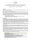
Positioning
473361163
Winding
473365515
Manual – IPOSplus®
23
3
System Description
Technology options / application modules
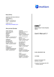
Overview of application modules
Flying saw
473369867
Internal Synchronous Operation ISYNC
(only MOVIDRIVE® B and MCH)
473374219
Rotatory positioning
473378571
The intelligent application modules in the technology option offer a new level of functionality. All the important machine data is easily accessible. There are almost no sources
for errors, since only those parameters required for the application have to be entered.
All relevant data, for example, terminal states or position values, can be observed using
a diagnostics tool during the ongoing operating process.
The functionality of each these modules is described in individual manuals.
24
Manual – IPOSplus®
System Description
Technical data
3.5
Technical data
3.5.1
MOVIDRIVE® B
Encoder resolution:
X15, motor encoder
X14, external encoder
X62, absolute encoder (including absolute
encoder from HIPERFACE®)
IPOSplus® always operates with 4096 increments/motor revolution
(Pre-requisite: Encoder resolution of 128, 512, 1024 or 2048 pulses/motor revolution
(any other encoder resolutions are not permitted) or resolver)
Maximum program length/program memory:
16 kByte corresponds to ca. 200 ... 250 Assembler commands
Command processing time:
the total in Task 1 und Task 2 ≤ 12 Assembler commands/ms):
Task 1: 1 ... 10 Assembler commands/ms
Task 2: 2 ... 11 Assembler commands/ms
Task 3: free computing time
Interrupts:
1 interrupt triggered by timer, error or touch probe interrupts task 1.
4 variable interrupts that interrupt task 2 and 3.
Variables:
1024, of which 128 (0 ... 127) can be stored in non-volatile memory
Value range: - 231 ... +(231 - 1)
System variable area
IPOS variables H453 to H560
Touch probe inputs:
2 inputs, processing time 200 µs
Sampling interval of analog inputs:
1 ms
Sampling interval of binary inputs:
1 ms
Binary inputs/outputs:
MOVIDRIVE® B:
DIO option:
DIP option:
8 inputs/6 outputs
8 inputs/8 outputs
8 inputs/8 outputs
Analog inputs/outputs:
MOVIDRIVE® B:
DIO option:
1 input (0 ... 10 V, ±10 V, 0 ... 20 mA, 4 ... 20 mA)
1 input (0 ... 10 V, ±10 V, 0 ... 20 mA)
2 outputs (±10 V, 0 ... 20 mA, 4 ... 20 mA)
3.5.2
3
MOVITRAC® B
Encoder resolution:
MOVITRAC® B has no encoder inputs but supports the position detection via binary
inputs (counter input).
For the technical data of the binary inputs, refer to section "Position detection via
binary inputs" (page 96)
Maximum program length/program memory:
8 kByte
Command processing time:
Task 1: 1 Assembler command/ms
Task 2: 2 Assembler commands/ms
Interrupts:
-
Variables:
1024, of which 128 (0 ... 127) can be stored in non-volatile memory
System variable area
IPOS variables H453 to H560
Touch probe inputs:
-
Sampling interval of analog inputs:
1 ms
Sampling interval of binary inputs:
5 ms
Binary inputs/outputs:
MOVITRAC® B
FIO21B option
6 inputs/3 outputs
7 Inputs
Analog inputs/outputs:
MOVITRAC® B
FIO11B option
1 input (0 ... 10 V)
1 input (± 10 V)
1 output (0 ... 20 mA, 4 ... 20 mA)
Manual – IPOSplus®
25
System Description
Technical data
3
3.5.3
26
MQx
Encoder resolution:
MQx module has no encoder inputs but supports the position detection via binary
inputs (counter input).
For the technical data of the binary inputs, refer to section "Position detection via
binary inputs" (page 96)
Maximum program length/program memory:
4 kByte
Command processing time:
Task 1: 1 Assembler command/ms
Task 2: 2 Assembler commands/ms
Interrupts:
-
Variables:
512, of which 128 (0 ... 127) can be stored in non-volatile memory
System variable area
IPOS variables H453 to H511
Touch probe inputs:
-
Sampling interval of analog inputs:
-
Sampling interval of binary inputs:
4 ms/input frequency at the counter inputs: max. 4 KHz
Binary inputs/outputs:
MQ.21./MQ.22.: 4 inputs and 2 outputs
MQ.32.: 6 Inputs
Analog inputs/outputs:
-
Manual – IPOSplus®
System Description
Reference documents
3.6
3
Reference documents
This document describes the IPOSplus® positioning and sequence control integrated in
MOVIDRIVE®.
The following reference list is an overview of the documents referred to in this documentation. You do not have to have read these documents to be able to program with
IPOSplus®; they simply offer additional information.
All the documents are available on the SEW-EURODRIVE website under
http://www.sew-eurodrive.de
3.6.1
3.6.2
3.6.3
3.6.4
3.6.5
General manuals
•
MOVIDRIVE® MDX60B/61B system manual
•
MOVITRAC® B system manual
•
Manuals for the MQx field distributors
Manuals for serial interfaces/fieldbuses
•
MOVIDRIVE® MDX60B/61B Communication and Fieldbus Unit Profile
•
DFx MOVIDRIVE® fieldbus interface
Manuals for synchronized axis movements
•
MOVIDRIVE® Electronic Cam, addendum to the system manual
•
MOVIDRIVE® Synchronous Operation Card Type DRS11
•
MOVIDRIVE® Internal Synchronous Operation
Manuals for application modules
•
MOVIDRIVE® Positioning with Absolute Encoder Option DIP11
•
MOVIDRIVE® Extended Positioning via Bus
•
MOVIDRIVE® Bus Positioning
•
MOVIDRIVE® Table Positioning with Bus Control
•
MOVIDRIVE® Modulo Positioning
Manuals for the MQx fieldbus interfaces
Manual – IPOSplus®
•
Drive System for Decentralized Installation: PROFIBUS Interfaces, Field Distributors
•
Drive System for Decentralized Installation: INTERBUS Interfaces, Field Distributors
•
Drive System for Decentralized Installation: DeviceNet/CANopen Interfaces, Field
Distributors
27
kVA
4
i
f
n
IPOS Variables
Introduction
Hz
P Hz
4
IPOS Variables
4.1
Introduction
The integrated positioning and sequence control system uses global variables that are
used by all the tasks and interrupts. There are no local variables that are only declared
either in a task or a function.
All variables (page 25) are 32-bit variables treated as signed integers during calculations and comparisons. In the user program, you must check that the final result of a calculation lies within the number range.
The number range can be represented as follows in a number circle:
4294967295
0xFFFF FFFF
-1
0 (decimal absolute)
0x0 (hexadecimal)
0 (IPOS value)
+
2147483648
0x8000 0000
-2147483648
2147483647
0x7FFF FFFF
2147483647
473666955
Example:
H0
=0
H1
H 0 = 2147 483 647, H1 = 1, H 3 = H 0 + H1 = −2147 483 648
H 0 = 4, H1 = 7, H 3 =
Each variable has an index that can be used to read and write variables using, for example, the Movilink command (_MoviLink/ MOVLNK). The index is calculated as follows:
Index = VarNo. + 11000
Example: H371 has the index 11371.
28
Manual – IPOSplus®
IPOS Variables
Overview of the system variables
4.2
kVA
i
f
n
4
Hz
P Hz
Overview of the system variables
Some IPOS variables are assigned set functions and are referred to as system variables
(page 25).
The symbolic names are available in the Compiler when one of the following lines is inserted at the start of the program:
#include <constb.h>
//symb. name MOVIDRIVE B system variables
The following table describes the function of the system variables and their names in the
Compiler and Assembler.
Variables in the range specified that are not assigned are reserved for internal functions
and cannot be used for user variables.
No.
Name
Compiler /
Assembler
128
Description
This variable can be used in a user-specific IPOS program. The variable is used by the application modules to
store the program identification.
360
...
452
Variable range for This variable range is assigned additional system variables if the technology options internal synchronous
internal synchro- operation or electronic cam are used. In all other cases, these can be used by the user as required.
nous operation or
electronic cam
453
ModuloCtrl /
MODULOCTRL
Control word for the modulo function (see also modulo function and IPOS parameter).
Bit 0 TargetReset_Off
Bit 0 = 0: The current positioning task is deleted (ModTagPos is set to ModActPos) if the positioning operation
is interrupted (for example, if the enable is revoked or if the controller inhibit or stop bit is set).
Bit 0 = 1: The target position is held even if the enable has been revoked or if the controller inhibit or the stop
bit has been set. If the drive is enabled again, it continues with the positioning process.
Bit 1 TargetGAZ_Select
Bit 1 = 0: Standard setting, 360° output corresponds to 216 incr.
Bit 1 = 1: Setting for increasing the resolution: 360° corresponds to the product from modulo numerator P961
x modulo encoder resolution P963. Positioning cannot be performed over several revolutions.
454
ModTagPos /
MOD.TAGPOS
Modulo target position
If a changed value is written to the modulo target position for an enabled inverter, positioning begins in output
units. The position setpoint (for H453.1 = 0) is set in 16 bit resolution in the unit H454 MODTAGPOS = k x
360° + 0 ... 360°= k x 216 + 0 ... (216 -1) (k = number of complete revolutions).
Once a new value has been written to the variable, only the target position within a revolution is visible in variable H454. We recommend that you also write the new value to a temporary variable for improved diagnostics.
Once position 454 has been written, the firmware calculates an incremental target H492. This causes H473 bit
19 "In position" to remain set for up to 1 ms.
455
ModActPos /
MOD.ACTPOS
Modulo actual position
The current modulo actual position moves (in 16 bit resolution when H453.1 = 0) between 0 and 216 increments (0° and 360°).
456
ModCount /
MOD COUNT
Increments within a modulo revolution before scaling to the output.
Display value of the internal temporary result when the incremental encoder value H509/H510/H511 (IPOS
encoder value) is converted to the modulo actual position H455.
For H456 = (IPOS encoder value) MOD (P961 x P963)
H455 = H456/(P961 x P963) x 216 (prerequisite: H453, bit 1 = 0)
See section "Modulo positioning". If 0 is written to H456, H455 is set automatically to 0.
Manual – IPOSplus®
29
kVA
4
i
f
n
IPOS Variables
Overview of the system variables
Hz
P Hz
No.
Name
Compiler /
Assembler
Description
473
StatusWord /
STAT.WORD
The status word can be used to query the operating status of the inverter.
Bit function with level "1"
0 No function
1 /Malfunction
2 Ready
3 Output stage on
4 Rotating field ON
5 Brake released
6 Brake applied
7 Motor standstill (from n < 20 rpm)
8 Parameter set
9 Speed reference (P400)
10 Speed window (P410)
11 Setpoint/actual comparison (P420)
12 Current reference (P430)
Bit function with level "1"
13 Imax signal (P442)
14 /Motor utilization 1
15 /Motor utilization 2
16 /DRS prewarning
17 /DRS lag error
18 DRS slave in position
19 IPOS in position (see also H493)
20 IPOS referenced
21 Reserved
22 /IPOS fault
23 Reserved
24 Current limit reached
25 LSM commutated
26 S-pattern profile is generated
27 Inverter in safe stop
28..31 Reserved
If the actual position of the drive is within the position window around the target position, the
"IPOS in position" bit is set even when the enable signal is removed or the controller inhibit is activated.
These two variables can be used together with the oscilloscope SCOPE function integrated in MOVITOOLS®
MotionStudio to record measured values.
Example: Measurement of the actual position value of a modulo axis. In the IPOS program, the command
H474 = H455 is called up cyclically and in SCOPE, channel 1 is set to IPOS variable H474 Low and channel 2
is set to IPOS variable H474 High.
474
Scope474 /
SCOPE 474
475
Scope475 /
SCOPE 475
476
DRS_Ctrl /
DRS CTRL.
Signal level of the binary outputs of the synchronous operation board DRS11, READ and SET.
DRS_Status /
DRS STATUS
Signal level of the binary inputs and status signals of the synchronous operation board type DRS11,
READ.
477
Bit terminal level
0 X40.9 AUSG0
1 X40.10 AUSG1
2..14 Reserved
15 Set hardware fault DRS (fault 48)
16..31 Reserved
Bit terminal level / status signals
0 X40.5 INP4 free input 1
1 X40.6 INP5 Free input 2
2 /DRS prewarning
3 /DRS lag error
4 DRS slave in position
5 Master standstill
6..31 Reserved
478
30
AnaOutpIPOS2 /
ANA.OUT IP2
Analog outputs of the terminal expansion board type DIO11, only SET.
The value of variable H478 is output on an analog output when the corresponding terminal is programmed to
"IPOS OUTPUT 2".
Option DIO11 is required for MOVIDRIVE® A and B; for MCH and MCS / MCV / MCV 40A, an output can be
programmed as a binary output or analog output.
Variable value physical outputOutput terminal assignment
- 10000..0..10000 AOV1/AOC1/AO01
P640 analog output AO1 = IPOS OUTPUT 2
- 10000..0..10000 AOV2/AOC2/AO01
P643 analog output AO2 = IPOS OUTPUT 2
Manual – IPOSplus®
IPOS Variables
Overview of the system variables
kVA
i
f
n
Hz
P Hz
No.
Name
Compiler /
Assembler
Description
479
AnaOutpIPOS /
ANA.OUT IP
Analog outputs of the terminal expansion board type DIO11, only SET.
OptOutpIPOS /
OPT.OUT IP
Binary outputs of the terminal expansion board types DIO11/DIP11, only SET.
The READ function can be performed for MOVIDRIVE® A using H482 and for MOVIDRIVE® B using H521.
If a DIO11 or DIP11 option is not inserter, virtual terminals can be set in status word 2 via fieldbus if, for example, P873 = STATUSWORD 2.
The bits of variable H480 are reproduced on the binary outputs of the basic unit if the relevant terminal is set
to IPOS OUTPUT.
If a binary output is toggled in IPOS, the physical output at the terminal is toggled 1 ms later if it is set as the
IPOS output.
480
The value of variable H479 is output on an analog output when the corresponding terminal is programmed to
"IPOS OUTPUT".
Option DIO11 is required for MOVIDRIVE® A and B; for MCH and MCS / MCV / MCV 40A, an output can be
programmed as a binary output or analog output.
Variable value physical outputOutput terminal assignment
- 10000..0..10000 AOV1/AOC1/AO01
P640 analog output AO1 = IPOS OUTPUT
- 10000..0..10000 AOV2/AOC2/AO01
P643 analog output AO2 = IPOS OUTPUT
Bit
IPOS name DIO (+ DIO)
DIO + DIP DIO + -fieldbus
P63x has an effect on DIO
0
1
2
3
4
5
6
7
8
9
10
11
12
13
14
15
481
StdOutpIPOS /
STD.OUT IP
Manual – IPOSplus®
4
DO10
DO11
DO12
DO13
DO14
DO15
DO16
DO17
X23:1
X23:2
X23:3
X23:4
X23:5
X23:6
X23:7
X23:8
(X23:1)
...
(X23:8)
X23:1
X23:2
X23:3
X23:4
X23:5
X23:6
X23:7
X23:8
X61:1
X61:2
X61:3
X61:4
X61:5
X61:6
X61:7
X61:8
X23:1
X23:2
X23:3
X23:4
X23:5
X23:6
X23:7
X23:8
DIP
DIP + fieldbus
Fieldbus
P63x has an effect on DIP P873 status
word 2
X61:1
X61:2
X61:3
X61:4
X61:5
X61:6
X61:7
X61:8
X61:1
X61:2
X61:3
X61:4
X61:5
X61:6
X61:7
X61:8
Bit 8
Bit 9
Bit 10
Bit 11
Bit 12
Bit 13
Bit 14
Bit 15
Binary outputs of the basic unit, only SET.
If a binary output is toggled in IPOS, the physical output at the terminal is toggled 1 ms later if it is set as the
IPOS output.
Bit
IPOS name
0
(0)
1
2
3
4
5
DB00
DO00 MQx
DO01
DO02
DO03
DO04
DO05
cannot be programmed, fixed assignment with "/Brake"
If P628 = IPOS OUTPUT (only MQx)
If P620 = IPOS OUTPUT
If P621 = IPOS OUTPUT
Only with MOVIDRIVE® B if P622 = IPOS OUTPUT
Only with MOVIDRIVE® B if P623 = IPOS OUTPUT
Only with MOVIDRIVE® B if P624 = IPOS OUTPUT
31
kVA
4
i
f
n
IPOS Variables
Overview of the system variables
Hz
P Hz
No.
Name
Compiler /
Assembler
Description
482
OutputLevel /
Signal level of the binary outputs, READ only.
OUTPUT LVL
Bit
IPOS name DIO (+ DIO) DIO + DIP DIO + -fieldDIP
DIP + field- Fieldbus
bus
bus
MOVIDRIVE® A
(MOVIDRIVE® B:
P63x has an effect on DIO
P63x has an effect on DIP P873 status
H521)
word 2
0
1
2
3
4
5
6
7
8
9
10
11
12
13
14
15
16
483
DB00
DO01
DO02
X23:1
X23:2
X23:3
X23:4
X23:5
X23:6
X23:7
X23:8
(X23:1)
...
(X23:8)
DB00
DO01
DO02
X23:1
X23:2
X23:3
X23:4
X23:5
X23:6
X23:7
X23:8
X61:1
X61:2
X61:3
X61:4
X61:5
X61:6
X61:7
X61:8
DB00
DO01
DO02
X23:1
X23:2
X23:3
X23:4
X23:5
X23:6
X23:7
X23:8
DB00
DO01
DO02
X61:1
X61:2
X61:3
X61:4
X61:5
X61:6
X61:7
X61:8
DB00
DO01
DO02
X61:1
X61:2
X61:3
X61:4
X61:5
X61:6
X61:7
X61:8
DB00
DO01
DO02
Bit 8
Bit 9
Bit 10
Bit 11
Bit 12
Bit 13
Bit 14
Bit 15
InputLevel /
Signal level of the binary inputs, READ only.
INPUT LVL
Bit
IPOS name DIO (+ DIO) DIO + DIP DIO + -fieldDIP
DIP + field- Fieldbus
bus
bus
P870 = staMOVIDRIVE® A
tus word 2
(MOVIDRIVE® B:
H520)
Depends on the basic unit, e.g. X13:1
DI00
0
X13:2
DI01
1
X13:3
DI02
2
X13:4
DI03
3
X13:5
DI04
4
X13:6
DI05
5
6
7
8
9
10
11
12
13
14
15
16
17
18
19
20
21
32
DB00
DO01
DO02
DO10
DO11
DO12
DO13
DO14
DO15
DO16
DO17
DI10
DI11
DI12
DI13
DI14
DI15
DI16
DI17
X22:1
X22:2
X22:3
X22:4
X22:5
X22:6
X22:7
X22:8
(X22:1)
...
(X22:8)
X22:1
X22:2
X22:3
X22:4
X22:5
X22:6
X22:7
X22:8
X60:1
X60:2
X60:3
X60:4
X60:5
X60:6
X60:7
X60:8
X22:1
X22:2
X22:3
X22:4
X22:5
X22:6
X22:7
X22:8
X60:1
X60:2
X60:3
X60:4
X60:5
X60:6
X60:7
X60:8
X60:1
X60:2
X60:3
X60:4
X60:5
X60:6
X60:7
X60:8
Bit 8
Bit 9
Bit 10
Bit 11
Bit 12
Bit 13
Bit 14
Bit 15
Manual – IPOSplus®
IPOS Variables
Overview of the system variables
kVA
i
f
n
Hz
P Hz
No.
Name
Compiler /
Assembler
Description
484
ControlWord /
CTRL.WORD
IPOSplus® control word (unit functions READ and SET).
The IPOSplus® control word can always be used, irrespective of the operating mode, control signal source and
setpoint source. The IPOSplus® control word is connected by an OR command with the terminal functions, the
fieldbus control word and the control word in the unit via the RS-485/RS-232 and the SBus.
Bit function with level "1"
0 No function
1 No enable
2 CW
3 CCW
4 n11/n21 (fixed setpoint 1)
5 n12/n22 (fixed setpoint 2)
6 Fixed setpoint selection
7 Parameter switchover (param. set 2)
8 Ramp switchover (ramp set 2)
9 Motor potentiometer up
10 Motor potentiometer down
11 External fault
12 Fault reset
13 Hold control
14 CW limit switch
15 CCW limit switch
Bit function with level "1"
16 Reserved
17 Reference cam
18 Reference travel start
19 Slave free running
20 Setpoint block
21 Reserved
22 DRS zero point set
23 DRS slave start
24 DRS teach in
25 Reserved
26 Reserved
27 Condition Monitoring switching signal:
Drive vibration warning
28 Condition Monitoring switching signal:
Vibration fault
29 Condition Monitoring switching signal:
Brake wear error
30 Controller inhibit
31 Reserved
485
T0_Reload /
T0 RELOAD
486
Reserved
487
Timer_2 /
TIMER 2
Time for user timer 2, READ and SET.
User time 2 counts upwards.
Value range: 0 ... 231 -1 ms.
488
Timer_1 /
TIMER 1
Time for user timer 1, READ and SET.
User timer 1 counts downwards to 0.
Value range: 0 ... 231 -1 ms.
489
Timer_0 /
TIMER 0
Time for user timer 0, READ and SET.
User timer 0 counts downwards to 0. An interrupt branch is performed when the timer value reaches 0 if the
SET INTERRUPT (SETINT) command is being used. The cycle time can be specified with the variable T0
RELOAD (H485) if a user timer is to be used cyclically with the SET INTERRUPT (SETINT) command. See
section "Task management and interrupts".
Value range: 0 ... 231 -1 ms.
Manual – IPOSplus®
4
READ and SET loading value for the user timer 0 cycle time. The cycle time can be specified with H485 if a
user timer (TIMER0 (H489)) is to be used cyclically with the SET INTERRUPT (SETINT) command. The time
value entered in H485 is reloaded automatically with this time value every time the timer 0 runs down (H489 =
0). Value range: 0 ... 231 -1 ms.
33
kVA
4
34
i
f
n
IPOS Variables
Overview of the system variables
Hz
P Hz
No.
Name
Compiler /
Assembler
Description
490
WdogTimer /
WD.TIMER
Time for the user watchdog, READ and SET.
The watchdog timer counts down to 0. The WATCHDOG ON (WDON) command activates the timer and
determines the cycle time.
Value range: 0 ... 231 -1 ms.
491
SetpointPos /
SETP.POS.
Current setpoint position, READ.
IMPORTANT: System control variable Value must not be overwritten.
The setpoint position always has the following unit, regardless of the encoder pulse count per revolution: 4096 Inc./motor revolution (encoder resolution ≥ 512).
The current setpoint position represents the absolute position that is currently valid for position
control in the travel job in progress. The changes of the setpoint position result from the calculated travel profile taking into account the positioning ramp, the travel speed, the ramp type etc. Once the
requested travel has been completed and the drive is in standstill, H491 corresponds to H492.
Value range: -231 ... 0 ... 231 -1 inc.
492
TargetPos /
TARGET POS
Current target position, READ and SET.
The target position always has the following unit, regardless of the encoder pulse count per revolution: 4096
Inc./motor revolution (encoder resolution ≥ 512).
This variable represents the current target position of the travel job currently in progress. H492 displays the
position in its absolute form.
Example:
1. current drive position: 50000 Inc.
2. GOR NOWAIT #-8000 Inc.
3. current target position:
42000 Inc.
Value range: -231 ... 0 ... 231 -1 inc.
If H492 is written directly (not using a GO command), H473, bit 19 "In position" remains set for up to 1 ms.
493
PosWindow /
POS.WINDOW
Positioning window, READ and SET. H493 is identical to P922.
The positioning window defines a distance range around the target position (H492) of a travel or stop command (GOx or ASTOP TARGET POSITION). As soon as the drive has reached the positioning window, the
signal "IPOS IN POSITION" is generated. This message is available via a binary output that is to be parameterized to the "IPOS IN POSITION" function and in the system variable H473, bit 19. The "IPOS IN POSITION" message is reset as soon as a GO command is placed.
The position window is always monitored provided an operating mode with IPOS is active (P700). The positioning accuracy is not affected by the value of the position window.
Setting range: 0 ... 50 ... 215 - 1 increments
494
LagWindow /
LAG WINDOW
Lag error window, READ and SET. H494 is identical to P923.
The lag error window defines the maximum permitted difference between the current setpoint position, which
the ramp generator specifies every 1 ms, and the actual position. If the specified value is exceeded, fault F42
(lag error) is triggered. The response to F42 must be set using parameter P834 "Response LAG ERROR".
Deactivation: You can deactivate the lag error monitoring by setting the P923 Lag error window to 0.
Setting range: 0 ... 5000 ... 231 - 1 increments
495
LagDistance /
LAG DISTAN
Lag distance, READ.
Value of the current lag distance in positioning (difference between setpoint and actual position).
Value range: 0 ... 231 - 1 increments
496
SLS_right /
SLS RIGHT
Software limit switch CW, READ and SET. H496 is identical to P920.
Limits travel in a clockwise direction. The value is given in user travel units.
Setting range: - 231 ... 0 user units ... 231 - 1 increments
497
SLS_left /
SLS LEFT
Software limit switch CCW, READ and SET. H497 is identical to P921.
Limits travel in a counterclockwise direction. The value is given in user travel units.
Setting range: - 231 ... 0 user units ... 231 - 1 increments
498
RefOffset /
REF.OFFSET
Reference offset, READ and SET. H498 is identical to P900.
The reference object allows for a shift of the machine zero without physically shifting the reference mark. The
following applies:
Machine zero = reference position + reference offset
The drive moves to the reference point during the reference travel and stops there. After the reference travel,
the machine zero is calculated with reference point and reference offset.
The reference offset is given in user travel units.
Setting range: - 231 ... 0 ... + 231 - 1
Manual – IPOSplus®
IPOS Variables
Overview of the system variables
kVA
i
f
n
Hz
P Hz
No.
Name
Compiler /
Assembler
Description
499
SetpPosBus /
SP.POS.BUS
Setpoint position bus, READ.
Contains the setpoint position which is sent via the fieldbus process data. The setpoint position is only
accepted if "POSITION LO" and "POSITION HI" are programmed in the PO-data description (parameter
group P87_).
500
TpPos2_VE /
TP.POS2VE
Only used in MOVIDRIVE® B; reserved in MOVIDRIVE® A.
The value of the virtual encoder H376 is stored in H599 if input DI03 has been activated (see also
_TouchProbe()/TOUCHP).
501
TpPos1_VE /
TP.POS1VE
Only used in MOVIDRIVE® B; reserved in MOVIDRIVE® A.
The value of the virtual encoder H376 is stored in H501 if input DI02 has been activated (see also
_TouchProbe()/TOUCHP).
502
TpPos2_Abs /
TP.POS2ABS
The touch probe positions are stored in the following variables:
503
TpPos1_Abs /
TP.POS1ABS
Encoder
504
TpPos2_Ext /
TP.POS2EXT
505
TpPos2_Mot /
TP.POS2MOT
506
TpPos1_Ext /
TP.POS1EXT
507
TpPos1_Mot /
TP.POS1MOT
508
IPOS counter
•
•
509
ActPos_Abs /
ACTPOS ABS
Current actual position of the DIP absolute encoder (SSI), READ.
IMPORTANT: System control variable Value must not be overwritten.
This actual position is determined via the signals which are active on plug connector X62 (DIP11A
option).
Unit: Increments depending on the encoder resolution.
510
ActPos_Ext /
ACTPOS EXT
READ current actual position external encoder.
IMPORTANT: System control variable Value must not be overwritten.
The actual position is determined via the track signals which are active on plug connector X14.
Position detection is only performed if connector X14 is used as the encoder input.
Unit: Increments depending on the encoder resolution.
511
ActPos_Mot /
ACTPOS.MOT
READ current actual position motor encoder.
IMPORTANT: System control variable Value must not be overwritten.
The actual position always has the following unit, regardless of the encoder pulse count per revolution: 4096 increments per motor revolution (encoder resolution 512 inc., exception: MQx with
NV26 has 24 Increments per motor revolution).
Manual – IPOSplus®
Motor encoder (X15)
External encoder (X14)
Absolute encoder (X62)
4
Encoder position
Touch probe 1
Touch probe 2
DI02
DI03
H511 ACTPOS.MOT H507 TP.POS1MOT
H505 TP.POS2MOT
H510 ACTPOS.EXT
H506 TP.POS1EXT
H504 TP.POS2EXT
H509 ACTPOS.ABS
H503 TP.POS1ABS
H502 TP.POS2ABS
Counter value for the frequency input (if it is activated via DIP switch S14)
High-resolution motor position (if the interpolated position signal is set via P916)
35
4
kVA
i
f
n
IPOS Variables
Overview of the system variables
Hz
P Hz
Furthermore, the following variables are assigned functions or reserved in
MOVIDRIVE B®:
36
No.
Name
Compiler /
Assembler
Description
512
...
515
Reserved
516
CCount_MotOn
Activate C track (zero pulse) counter for motor encoder X15.
0 = Counter disabled/1 = Counter enabled
517
CCount_ExtOn
Activate C track (zero pulse) counter for external encoder X14.
0 = Counter disabled/1 = Counter enabled
518
CCount_Mot
Counting of the zero pulses at X15. Low word is incremented with every zero pulse at the motor encoder
X15.
519
CCount_Ext
Counting of the zero pulses at X14. Low word is incremented with every zero pulse at the external encoder
X14.
520
InpLevelB /
INPUTLVLB
MOVIDRIVE® B
(MOVIDRIVE® A:
H483)
Signal level of the binary inputs, READ only.
Bit
IPOS
name
0
1
2
3
4
5
6
7
DI00
DI01
DI02
DI03
DI04
DI05
DI06
DI07
8
9
10
11
12
13
14
15
16
17
18
19
20
21
22
23
DI10
DI11
DI12
DI13
DI14
DI15
DI16
DI17
DIO
(+ DIO)
DIO + DIP
DIO +
fieldbus
DIP
DIP +
fieldbus
Fieldbus
P870 =
control
word 2
Depends on the basic unit, e.g. X13:1
X13:2
X13:3
X13:4
X13:5
X13:6
X16:1
X16:2
X22:1
X22:2
X22:3
X22:4
X22:5
X22:6
X22:7
X22:8
(X22:1)
...
(X22:8)
X22:1
X22:2
X22:3
X22:4
X22:5
X22:6
X22:7
X22:8
X60:1
X60:2
X60:3
X60:4
X60:5
X60:6
X60:7
X60:8
X22:1
X22:2
X22:3
X22:4
X22:5
X22:6
X22:7
X22:8
X60:1
X60:2
X60:3
X60:4
X60:5
X60:6
X60:7
X60:8
X60:1
X60:2
X60:3
X60:4
X60:5
X60:6
X60:7
X60:8
Bit 8
Bit 9
Bit 10
Bit 11
Bit 12
Bit 13
Bit 14
Bit 15
Manual – IPOSplus®
IPOS Variables
Overview of the system variables
No.
Name
Compiler /
Assembler
Description
521
OutpLevelB /
OUTPUTLVLB
MOVIDRIVE® B
(MOVIDRIVE® A:
H482)
Signal level of the binary outputs, READ only.
kVA
i
f
n
Hz
P Hz
Bit
IPOS
name
DIO (+
DIO)
DIO + DIP
DIO + fieldbus
DIP
DIP +
fieldbus
Fieldbus
P873 = status word 2
0
1
2
3
4
5
6
7
8
9
10
11
12
13
14
15
16
17
18
19
20
21
DB00
DO01
DO02
DO03
DO04
DO05
DO10
DO11
DO12
DO13
DO14
DO15
DO16
DO17
DB00
DO01
DO02
DO03
DO04
DO05
X23:1
X23:2
X23:3
X23:4
X23:5
X23:6
X23:7
X23:8
DB00
DO01
DO02
DO03
DO04
DO05
X23:1
X23:2
X23:3
X23:4
X23:5
X23:6
X23:7
X23:8
X61:1
X61:2
X61:3
X61:4
X61:5
X61:6
X61:7
X61:8
DB00
DO01
DO02
DO03
DO04
DO05
X23:1
X23:2
X23:3
X23:4
X23:5
X23:6
X23:7
X23:8
DB00
DO01
DO02
DO03
DO04
DO05
X61:1
X61:2
X61:3
X61:4
X61:5
X61:6
X61:7
X61:8
DB00
DO01
DO02
DO03
DO04
DO05
X61:1
X61:2
X61:3
X61:4
X61:5
X61:6
X61:7
X61:8
DB00
DO01
DO02
DO03
DO04
DO05
Bit 8
Bit 9
Bit 10
Bit 11
Bit 12
Bit 13
Bit 14
Bit 15
(X23:1)
...
(X23:8)
522
RecStatS1 /
SBUS1REC
Status word for receiving SCOM data objects (double words) via the system bus
A receive bit is reserved for each data object set up using _SBusCommDef/SCOM. The first receive object
initialized in the IPOS program is assigned bit 0, the second one bit 1, etc. When MOVIDRIVE® receives a
telegram from an initialized receive object, the corresponding bit is set. The bit can only be reset in the user
program. Event-driven telegrams can be sent and received via the SBus if a variable interrupt has been set
for the corresponding bit in H522. The bit reset must make up the last command in the interrupt routine.
When designing a process image, the user must ensure that no side effects are caused when the same
object is received during processing (cyclical receipt of an object). To reset the bit, use the BITCLEAR command so that receive bits in other transfers are not lost.
523
RecStatS2 /
SBUS2REC
Only with CAN bus via DFC11B: Status word for receiving SCOM data objects (double words) via the
CAN bus
A receive bit is reserved for each data object set up using _SBusCommDef/SCOM. The first receive object
initialized in the IPOS program is assigned bit 0, the second one bit 1, etc. When MOVIDRIVE® receives a
telegram from an initialized receive object, the corresponding bit is set. The bit can only be reset in the user
program. Event-driven telegrams can be sent and received via the SBUS if a variable interrupt has been set
for the corresponding bit in H523. The bit reset must make up the last command in the interrupt routine.
When designing a process image, the user must ensure that no side effects are caused when the same
object is received during processing (cyclical receipt of an object). To reset the bit, use the BITCLEAR command so that receive bits in other transfers are not lost.
Manual – IPOSplus®
4
37
4
38
kVA
i
f
n
IPOS Variables
Overview of the system variables
Hz
P Hz
No.
Name
Compiler /
Assembler
Description
524
IPOS_Setp /
IPOS_SETP
IPOS setpoint, correcting variable of the PID controller when H540 = 1. When H540 = 0 or 2 the setpoint
can also be written directly from the user program.
H524 can be used as a torque setpoint or speed setpoint when P100 Setpoint source = IPOS and P700
Operating mode 1 = xxx&M-control, CFC or SERVO.
1 increment in H524 then corresponds to 0.21 rpm setpoint speed or 0.01% IN torque setpoint
525
...
529
Reserved
530
VarIntReq /
VARINTREQ
If the corresponding request bit of a variable interrupt is set, a variable interrupt is triggered irrespective of
the actual interrupt condition. The relevant variable interrupt must be activated beforehand.
Bit 0: Request for variable interrupt 0
Bit 1: Request for variable interrupt 1
Bit 2: Request for variable interrupt 2
Bit 3: Request for variable interrupt 3
540
PID_Mode /
PID.MODE
Operating mode of the PID controller, H540 and P260 are identical.
0 = Controller deactivated (default)
1 = Control active
2 = Step response (open control system)
541
PID_K_p /
PID.KP
PID-controller: Factor of the proportional component, H541 and P263 are identical, 3 decimal places; 0 <=
KP <= 32000 (= 32,000); default: 1000 (= 1,0)
542
PID_Outp_P /
PID.OUTPP
PID-controller: Current value of the controller's P-component
543
PID_Outp_I /
PID.OUTPI
PID-controller: Current value of the controller's I-component
The value for the l-component is in the high word, the internal components for decimal places are in the low
word, for example, H543 = 0x30000 -> l-component = 3.
544
PID_Outp_D /
PID.OUTPD
PID-controller: Current value of the controller's D-component
545
PID_Feedf /
PID.FEEDF
PID controller precontrol value; H545 and P266 are identical
-32000 <= Precontrol <= 32000; default: 0
546
PID_Command /
PIDCOMMAND
PID-controller: Setpoint, H546 and P271 are identical
When P270 = 0 (= "Parameter"), P271/H546 contains the required process setpoint
-32000 <= Setpoint <= 32000 (for speed control, 1 increment corresponds to 0.2/min); default: 0
547
PID_CmdAdr /
PID.CMDADR
PID-controller: Setpoint address, H547 and P272 are identical
When P270 = 1 (= "IPOS variable"), P272/H547 contains the address of the IPOS variable with the setpoint;
default: 0
548
PID_CmdScale /
PID.CMDSCA
PID controller: Factor for scaling the setpoint, H548 and P274 are identical, weighted with 3 decimal places
-32000 (-32,000) <= KSetpoint <= 32000 (32,000); default: 1000 (1,0)
549
PID_ActAdr /
PID.ACTADR
PID controller: Address of actual value, H549 and P276 are identical
When P275 = "IPOS variable", P276/H549 contains the address of the IPOS variable; default: 0
550
PID_ActScale /
PID.ACTSCA
PID-controller. Scaling factor of the filtered actual value, H550 and P277 are weighted identically with 3 decimal places -32,000 <= KActual value <= 32,000; default: 1000 (1,0)
551
PID_ActNorm /
PID.ACTNOR
PID controller: Filtered and scaled actual value, diagnostics value
552
PID_ActOffset /
PID.ACTOFF
PID controller: Integer, permanent offset of actual value, H552 and P278 are identical
-32000 (-32000) <= Offset <= 32000 (32000); default: 0
553
PID_ActMin /
PID.ACTMIN
PID controller: Minimum value for actual value after smoothing, scaling and offset, H553 and P280 are identical.
-32000 (-32000) <= xe,min <= 32000 (32000); Default: 0
554
PID_ActMax /
PID.ACTMAX
PID controller: Maximum value for actual value after smoothing, scaling and offset, H554 and P281 are identical.
-32000 (-32000) <= xe,max <= 32000 (32000); default: 10000 (10,0)
555
PID_LimitMin /
PID.LMTMIN
PID controller: Minimum output value, H555 and P282 are identical
-32000 (-32000) <= xcontroller,min <= 32000 (32000); default: -1000 (-1,0)
556
PID_Limit_Max /
PID.LMTMAX
PID controller: Maximum output value, H556 und P283 are identical
-32000 (-32000) <= xcontroller,max <= 32000 (32000); default: 10000 (1,0)
Manual – IPOSplus®
IPOS Variables
Overview of the system variables
No.
Name
Compiler /
Assembler
Description
557
PID_SetpMin /
PID.SETMIN
PID controller: Minimum output value for correcting variable, H557 and P284 are identical
-32000 (-32000) <= xa,min <= 32000 (32000); Default: 0
558
PID_SetpMax /
PID.SETMAX
PID controller: Maximum output value for correcting variable, H558 and P285 are identical
-32000 (-32000) <= xa,max <= 32000 (32000); Default: 7500 (7,5)
559
PID_Status /
PID.STATUS
PID-controller status word
Bit 0 = Total of actual value and offset exceeds limit xemin
Bit 1 = Total of actual value and offset exceeds limit xemax
Bit 2 = Value of the controller P-component is limited
Bit 3 = I-component of the controller is deactivated
Bit 4 = Value of the controller I-component is limited
Bit 5 = Value of the controller D-component is limited
Bit 6 = PID-controller correcting variable is limited
Bit 7 = Total of PID-controller correcting variable and presetting is limited
560
Reserved
Manual – IPOSplus®
kVA
i
f
n
4
Hz
P Hz
39
kVA
5
i
f
n
Task Management and Interrupts
Introduction
Hz
P Hz
5
Task Management and Interrupts
5.1
Introduction
IPOSplus® can process several subprograms at the same time. One subprogram corresponds to one task. The following functions can trigger interrupts for task 1:
•
Timer0 overflow
•
System error/unit error
•
Touch probe DI02
MOVIDRIVE® B can interrupt task 2 and task 3 with 4 additional interrupts, which are
triggered by the comparison with a variable value.
MOVIDRIVE® A can execute 2 subprograms – task1 and task 2 – running independently
of each other.
MOVIDRIVE® B can execute 3 subprograms – task1, task 2 and task 3 – running independently of one another.
You can run MOVIDRIVE® B in the same way as MOVIDRIVE® A.
The following variables are global. All tasks and interrupts use the same variables:
•
H0 - H511 for MOVIDRIVE® A
•
H0 - H1023 for MOVIDRIVE® B
There are no local variables that are only declared in either a task or a function. There
is an overview of the areas reserved for system variables in section "IPOS variables /
Overview of the System Variables".
You can enter the commands in a program window. You must create all program sections using the same language: Assembler or Compiler.
5.2
Task management for MOVIDRIVE® A and B
Task 1 is the main program. You can start task 1 using the lightning symbol in the toolbar
or using the keypad (P931). Initialize and start task 2 and task 3 using program commands. Task 3 is only available with MOVIDRIVE® B. The interrupt is initialized using
program commands and triggered using an interrupt event. If you stop task 1 using the
STOP icon in the toolbar, this stops the entire IPOS processing. The DBG keypad can
be used to stop all tasks by setting parameter P931 to STOP. When P931 = STOP, only
task 1 is stopped. After a restart the program continues where it was interrupted.
40
Manual – IPOSplus®
Task Management and Interrupts
Task management for MOVIDRIVE® A and B
kVA
i
f
n
5
Hz
P Hz
Toolbar for MOVIDRIVE® A
473926155
[1] = Status of task 1: START = started
[2] = Status of task 2: PSTOP = stopped
[3] = Lightning icon to start task 1
[4] = STOP icon to stop the entire IPOS processing
Toolbar for MOVIDRIVE® B
474186507
[1] = Status of task 1: PSTOP = stopped
[2] = Status of task 2: PSTOP = stopped
[3] = Status of task 3: PSTOP = stopped
[4] = Lightning icon to start task 1
[5] = STOP icon to stop the entire IPOS processing
IPOSplus® processes a task cyclically. A task starts with the first command again once
the last command has been completed. If you only want to execute an initialization routine in task 1 once, you can exclude this program section using an endless loop.
main()
{
// Program code only initialization
while(1)
{
// cyclical program code
}
}
Manual – IPOSplus®
41
5
kVA
i
f
n
Hz
P Hz
Task Management and Interrupts
Task management for MOVIDRIVE® A and B
The following table gives an overview of the functions and properties of the tasks and
interrupts.
Task 1
Task 2
Task 3 (only
MOVIDRIVE® B)
_SetTask2(ST
2_START,
Task2Name);
or TASK2
START Mxx
Not available
Start
MOVIDRIVE® B
_SetTask(ST2
_START,
Task2Name);
or TASK
TASK2,
START Mxx
_SetTask(ST3_S
TART,
Task3Name); or
TASK TASK3,
START Mxx
Stop
MOVIDRIVE® A
STOP icon or
_SetTask2(ST
2_STOP,
Task2Name);
or TASK2
STOP Mxx
Not available
STOP icon or
_SetTask(ST2
_STOP,
Task2Name);
or TASK
TASK2, STOP
Mxx
STOP icon or
_SetTask(ST3_S
TOP,
Task3Name); or
TASK TASK3,
STOP Mxx
Start
MOVIDRIVE® A
Lightning icon
or P931 in
keypad
STOP icon or
P931 in keypad
Stop
MOVIDRIVE® B
"Task1" interrupt
Variable
interrupt
(only
MOVIDRIVE®
B)
Not available
With the
defined interrupt event
With the
defined interrupt event
Not available
As task 1
As task 1 or as
assigned task
2 or 3
Not available
With other
task 1 interrupt
with higher priority
Not available
With variable
interrupt
With variable
interrupt
With other
task 1 interrupt
with higher priority
With variable
interrupt in the
same task with
higher priority
Yes
No1)
No1)
Yes
No1)
Command processing time
MOVIDRIVE® A
1 Assembler
command/ms
2 Assembler
commands/ms
Not available
Assembler
command/ms
Not available
Command processing time
MOVIDRIVE® B
1 ... 10
Assembler
commands/
ms, factory
setting: 1 command/ms
2 ... 11 Assembler commands/ms,
factory setting: 2 commands/ms
min. 1 command per ms;
additional commands are processed
depending on
the processor
utilization
As task 1
As task to
which the
interrupt is
assigned (task
2 or 3)
Interrupt
MOVIDRIVE® A
Via "Task1"
interrupt
Cannot be
interrupted
Interrupt
MOVIDRIVE® B
Via "Task1"
interrupt
Debug with
breakpoint and
single step
1) Copy commands to task 1 for debugging.
42
Manual – IPOSplus®
Task Management and Interrupts
Tasks for MOVIDRIVE® A
5.3
kVA
i
f
n
5
Hz
P Hz
Tasks for MOVIDRIVE® A
In addition to the general section in chapter "Task Management for MOVIDRIVE® A and
B", this section provides specific implementation information for MOVIDRIVE® A: The
motion sequence with the positioning commands is programmed in task 1.
Program the following functions in task 2:
•
Rapid, time-critical processes
•
Calculations
•
Monitoring for system values
•
Communication with the SEW operator terminals
•
Copying variables cyclically to the oscilloscope variables H474, H475
•
Formatting the fieldbus/SBus process data with a machine control function or
another MOVIDRIVE®
In this way, IPOSplus® also performs these functions when the interrupt routine is active
in task 1.
5.4
Tasks for MOVIDRIVE® B
In addition to the general section in chapter "Task Management for MOVIDRIVE® A and
B", this section provides specific implementation information for MOVIDRIVE® B:
5.4.1
Processing time for task 1 / task 2
The factory setting for the task processing time is:
•
Task 1: 1 command/ms (P938 = 0)
•
Task 2: 2 commands/ms
You can speed up the processing time in both tasks to include up to 9 additional commands per ms. You can assign the additional commands for task 1 using parameter
P938 (index 8888) and for task 2 using parameter P939 (index 8962). This means that
a maximum of 1 + 9 = 10 commands can be performed in task 1 and 2 + 9 = 11 in
task 2.
Manual – IPOSplus®
43
5
kVA
i
f
n
Hz
P Hz
Task Management and Interrupts
Tasks for MOVIDRIVE® B
When you assign the maximum number of additional commands/ms to task 1 and task
2, the following combinations are possible:
Task 1
Task 2
P938
Command/ms
P939
Command/ms
0
1
9
11
1
2
8
10
2
3
7
9
3
4
6
8
4
5
5
7
5
6
4
6
6
7
3
5
7
8
2
4
8
9
1
3
9
10
0
2
Example: P938 = 2, P939 = 3 => Task 1 processes 3 commands/ms, task 2 processes
5 commands/ms
5.4.2
Task 3
Task 3 is available from the B series units. Task 3 processes at least 1 command/ms.
Depending on the unit configuration and on the setting of P938/P939, task 3 will perform
additional commands. 20 ... 40 commands/ms is the typical number of commands for
task 3. The absolute resource requirements for command processing is ca. 20 ... 40%
lower in task 3 compared with task 1 or task 2. Application components, for which the
guaranteed run time of the individual program lines is not important, are processed
faster in task 3.
5.4.3
Implementation information
In contrast to MOVIDRIVE® A, you program the motion sequence in task 1 or task 3.
Program the following functions in task 2 or task 3:
•
Rapid, time-critical processes
•
Calculations
•
Monitoring for system values
•
Communication with the SEW operator terminals
•
Copying variables cyclically to the oscilloscope variables H474, H475
•
Formatting the fieldbus/SBus process data with a machine control function or
another MOVIDRIVE®
In this way, IPOSplus® also performs these functions when the interrupt routine is active
in task 1.
Note that in contrast to task 3, the processing time per command in task 2 is deterministic.
44
Manual – IPOSplus®
Task Management and Interrupts
Interrupts
5.4.4
kVA
i
f
n
5
Hz
P Hz
Example
MOVIDRIVE® B positions a travel drive. A PLC controls MOVIDRIVE® via a fieldbus.
Change the individual parameters directly on MOVIDRIVE® using SEW keypads.
Proposed solution:
Task 1: Programming the motion sequence
Task 2: HMI communication with the operator terminal
Task 3: Fieldbus communication with the PLC
It is important to distribute the additional commands correctly, depending on the application:
5.5
•
Interrupt-oriented programs:When a user program is interrupt-oriented and the
task 1 interrupts should be processed quickly, task 1 must be assigned a high
calculation priority using additional commands in P938.
•
Runtime-optimized programs:If, for example, process data is to be converted in
IPOS, this must be done as quickly as possible. Task 3 can be used to process
convert routines as quickly as possible. In this case, task 1 and task 2 should be
assigned as few additional commands/ms as possible. This ensures the fastest total
application performance if tasks 1 and 2 run with the minimum speed.
Interrupts
An interrupt - triggered by an event - interrupts the processing of the task it is assigned
to. The entire interrupt routine is run through once, as long as it is not interrupted by an
interrupt with a higher priority of the same task.
An interrupt that is activated by _SetInterrupt() or SETINT can be triggered by a timer0
overflow, a system/unit fault or touch probe DI02 and interrupts task 1.
In MOVIDRIVE® B, up to 4 additional variable interrupts can be activated using
_SetVarInterrupt() or VARINT. They interrupt task 2 or task 3 as required.
The response time for task 1 interrupts (unit fault, DI02 touch probe or T0_overflow) is
dependent on the number of activated interrupts (1 interrupt <= 1ms, 2 interrupts <=
2ms, 3 interrupts <= 3ms). The response time for variable interrupts is dependent on the
number of activated interrupts <= 1ms.
If an interrupt is triggered during a wait command, the waiting time of the command continues to run in the background. Once the program has jumped back to the task, it only
has to wait the remaining time before continuing.
Manual – IPOSplus®
45
5
kVA
i
5.5.1
f
n
Hz
P Hz
Task Management and Interrupts
Interrupts for MOVIDRIVE® A and B
Example
A WAIT 1000 ms command in task 1 is interrupted after 500 ms. If the processing of task
1 is resumed after 175 ms, the remaining runtime is 325 ms.
5.6
Interrupts for MOVIDRIVE® A and B
The following interrupts can be used in MOVIDRIVE® A units:
•
Timer0 overflow (H489) interrupt
Priority = 1 (lowest priority)
•
Touch probe DI02 interrupt
Priority = 2
•
Error interrupt
Priority = 3 (highest priority)
Task 1 is interrupted each time. In theory, a timer0, a touch probe and an error interrupt
can be active at the same time. An interrupt assigned a higher priority can interrupt the
processing of another interrupt. The DISABLE argument deactivates all interrupts. (see
_SetInterrupt or SETINT)
5.6.1
Interrupt activation
Compiler: _SetInterrupt(event ,myfunction );
Activates an interrupt. When the event event occurs, the function myfunction is performed instead of task 1.
Assembler: SETINT event, Mxx
Activates an interrupt. When the event event occurs, the commands from label Mxx are
performed instead of task 1.
5.6.2
Error interrupt
The entire interrupt routine is run through once if an error occurs. After one run-through,
an Assembler command from task 1 is processed before the system checks whether the
error still occurs. If the error is still present, the interrupt routine is processed again. To
remain in the interrupt routine until the error is no longer present, the routine must contain a loop that fulfills this condition.
Depending on the fault response set in parameter group 83x or using the command
_FaultReaction or SETFR, the program acts as follows:
46
•
No interrupt is triggered for a specific fault if the fault response of this fault is set to
NO RESPONSE.
•
If the fault response of a fault xy is set to "... and warning", task 1 is continued from
the same place once the fault has been reset.
•
If the fault response of a fault xy is set to "... and fault", IPOS is restarted once the
fault has been reset and the variables are reinitialized with the values from the
EEPROM. Note: In this case, you can store important variable values protected
against power failure with the MEM or MOVILINK command before resetting the
error. In doing so, note that the number of permissible write accesses must not be
exceeded (see MEM or _Memorize() ).
Manual – IPOSplus®
Task Management and Interrupts
Interrupts for MOVIDRIVE® A and B
Sample
kVA
i
f
n
5
Hz
P Hz
fnErrorInterrupt()
{
H2++;
while( !(StatusWord & 0b10))
{
//only leave while-loop when drive is fault-free
H1++;
}
}
main()
{
_SetInterrupt(SI_ERROR, fnErrorInterrupt);
while(1)
{
H0++;
}
}
H0 is incremented as long as the inverter is functioning correctly. If a fault occurs, H2 is
increased by one and H1 is incremented until the inverter functions correctly. Depending
on the fault response set, the system either continues processing with the current values
in task 1, or IPOS is restarted using the values from the EEPROM.
5.6.3
Touch probe DI02 interrupt
The entire interrupt routine is run through once if the touch probe has been released with
the command _TouchProbe (condition) or TOUCHP and the edge condition is fulfilled.
Then processing for task 1 continues. The interrupt routine is only called a second time
when the touch probe is released again and the condition is fulfilled. (See also the command _TouchProbe or TOUCHP).
Sample
fnTouchInterrupt()
{
H0++;
}
/*=============================================
Main function (IPOS initial function)
===============================================*/
main()
{
_SetInterrupt( SI_TOUCHP1,fnTouchInterrupt); //Act. interrupt routine
TouchProbe( TP_EN1 );
while (1) {H1 = H1 +1;}
}
H0 is increased by 1 once.
If the touch probe command is also called in the while loop or in the fnTouchInterrupt,
the interrupt would respond to all changes in edge signal on DI02.
Typical applications for the touch probe are: Relative positioning for de-stacking equipment or register loop control for processes with a continuous material flow.
Manual – IPOSplus®
47
5
kVA
i
f
n
Hz
P Hz
5.6.4
Task Management and Interrupts
Interrupts for MOVIDRIVE® A and B
Timer0 interrupt
The entire interrupt routine is run through once when the timer has elapsed (=0). After
one run-through, an Assembler command from task 1 is processed before the system
checks whether the time = 0. Once the condition is fulfilled, processing branches back
to the interrupt routine.
The cycle time can be set in variable H485 T0_Reload to trigger a timer0 interrupt at
equal intervals. This cycle time is used to reload the timer0 automatically when it occurs
in the interrupt routine
INFORMATION
Since the timer0 counts backwards, the interrupt condition would be fulfilled permanently if T0_Reload = 0 and the value of the timer has not been changed in the interrupt routine.
This results in the following options:
Sample
•
If a program section is to be processed at equal intervals with the timer0 interrupt,
the timer0 must be reloaded with the T0_Reload, for example.
•
If a program section is to be run through once with the timer0 interrupt at a defined
time after IPOS has been started, the timer0 must be set to -1 in the interrupt.
fnTimerInterrupt()
{
H0 = H0 +1;
T0_Reload = 10000; //Reload timer 0 automatically with 10 s
_SetInterrupt( SI_TIMER0,fnTimerInterrupt); // Activate interrupt
}
main()
{
while (1) {H1 = H1 +1;}
}
H0 is increased by 1 every 10 s.
48
Manual – IPOSplus®
Task Management and Interrupts
Variable interrupts with MOVIDRIVE® B
5.7
kVA
i
f
n
5
Hz
P Hz
Variable interrupts with MOVIDRIVE® B
All interrupts in MOVIDRIVE® B units are the same as those used in MOVIDRIVE® A
(see section "Task Management for MOVIDRIVE® A and B"), plus 4 additional variable
interrupts.
The interrupts for specific variable values can, for example, respond to
5.7.1
•
A quantity value
•
All timers 0, 1 and 2
•
The fact that an axis position of its own a or different axis has been reached
•
A change in an I/O signal
•
A certain inverter status (H473)
•
New data that is to be received or sent by the SBus
Calling up the variable interrupt
Compiler:
_SetVarInterrupt(pData ,myfunction);
Activates a variable interrupt with the data structure as of the variable pData, which runs
the myfunction function, when the interrupt event occurs.
Assembler:
VARINT Hxx, Mxx
Activates a variable interrupt with the data structure as of variable Hxx, which performs
the commands as of the Mxx label, when the interrupt event occurs.
The following properties and functions of the variable interrupt can be defined in the data
structure (see also the command _SetVarInterrupt or VARINT):
Manual – IPOSplus®
•
The task to be interrupted - task 2 or task 3
•
Sequential number of the interrupt (0... 3)
•
Reference variable and the value to be compared with each other
•
Type of the mathematical comparison (==, <, edge...)
•
Processing time: either as long as the condition is fulfilled or once each time the
condition is fulfilled (edge-triggered)
•
Priority of the interrupt
•
Value of the reference variable used to trigger the interrupt
49
5
kVA
i
f
n
Hz
P Hz
Task Management and Interrupts
Variable interrupts with MOVIDRIVE® B
INFORMATION
The data structure of the command is described in the system function (Compiler –
functions / Assembler – commands).
The behavior of the interrupt can by adapted dynamically during runtime, by either
5.7.2
•
Changing the data structure and then calling the command again (necessary if, for
example, the CompVar value used for the comparison changes) or
•
calling the command with a different data structure but with the same value in
variable H+1 (IntNum).
IPOS access to the internal interrupt control
Information as to whether a variable interrupt has been requested can be seen in the
IPOSplus® program in the variable uVarEventRequest (H530 bit 0 to 3). These "Request"
bits can also be written in the IPOSplus® program.
uVarEventRequest H530.0
Request for variable interrupt 0
uVarEventRequest H530.1
Request for variable interrupt 1
uVarEventRequest H530.2
Request for variable interrupt 2
uVarEventRequest H530.3
Request for variable interrupt 3
In this way, for example, the request bit can be set for test purposes during initial startup
up regardless of the actual interrupt condition and a variable interrupt can be triggered
(as long as the corresponding variable interrupt has been activated beforehand).
A variable interrupt can be used to configure time-controlled program processing, for example, the cyclical calculation of acceleration from a speed.
In addition, when a high-priority variable interrupt is being processing, you can delete a
pending, lower-priority interrupt by deleting the corresponding request bit.
Sample
50
The transport axis of a filling machine should head for a metering unit using DO01 when
it moves past the position 5° on the machine. The output should be deactivated 200 ms
later irrespective of the speed and axis position.
Manual – IPOSplus®
Task Management and Interrupts
Variable interrupts with MOVIDRIVE® B
Example solved in
the Compiler
kVA
i
f
n
5
Hz
P Hz
Required parameter settings
P620 = IPOS output, P960 = for example SHORT
/*===========================================
IPOS source file
============================================*/
#include <constb.h>
#include <iob.h>
// necessary parameter settings:
// P620 = IPOS output, P960 = for example SHORT
VARINT hOPENvalve, hCLOSEvalve;
fnTask3()
{ //Task 3 is only needed to activate VarInt.
H1 = H1;
//dummy command
}
fnOPENvalve()
{ //Switch on metering unit
Timer_2 = 0;
//Reset timer 2 to 0
hCLOSEvalve.Mode = 2;
//Activate stop-IRQ
_SetVarInterrupt( hCLOSEvalve,fnCLOSEvalve );
_BitSet( StdOutpIPOS, 1 );
//Set DO01
}
fnCLOSEvalve()
{ //Switch off metering unit
_BitClear( StdOutpIPOS, 1 );
//Delete DO01
hCLOSEvalve.Mode = 0;
//Deactivate stop-IRQ
_SetVarInterrupt( hCLOSEvalve,fnCLOSEvalve );
}
/*=============================================
Main function (IPOS initial function)
===============================================*/
main()
{ //Initialization part
hOPENvalve.Control = 2;
//Interrupt task3
hOPENvalve.IntNum =0;
//continuous no.
hOPENvalve.SrcVar = numof ( ModActPos );
//Modulo motor encoder
hOPENvalve.CompVar = 910;
// 5° on the machine = 5° x 910/65536
hOPENvalve.Mode = 12;
// once when >= 5°
hOPENvalve.Priority = 6;
// middle priority
hCLOSEvalve.Control = 2;
//Interrupt task3
hCLOSEvalve.IntNum = 1; //continuous no.
hCLOSEvalve.pSrcVar = numof ( Timer_2 ) ;
//Timer 2
hCLOSEvalve.CompVar = 200; //deactivate after 200 ms
hCLOSEvalve.Mode = 0;
//Deactivate timer-IR first
hCLOSEvalve.Priority = 7;
Manual – IPOSplus®
51
5
kVA
i
f
n
Hz
P Hz
Task Management and Interrupts
Variable interrupts with MOVIDRIVE® B
// Activate interrupt routine and task3
_SetTask(ST3_START, fnTask3);
_SetVarInterrupt( hOPENvalve,fnOPENvalve );
/*------------------------------------Main program loop
--------------------------------------*/
while(1)
{ //cyclical program section ...
} //End while (1)
} //End main()
Example solved in
the Assembler
Necessary parameter settings:
P620 = IPOS output, P960 = for example SHORT
474256139
52
Manual – IPOSplus®
Position Detection and Positioning
Encoder evaluation
6
Position Detection and Positioning
6.1
Encoder evaluation
kVA
i
f
n
6
Hz
P Hz
MOVIDRIVE® offers various options for positioning:
•
external encoders
•
Motor encoder (incremental encoder/resolver)
•
Hiperface® encoder (absolute encoder)
•
SSI absolute encoder
The values are provided in system variables for processing.
The connections for the motor encoder (X15) and external encoder (X14) are in the control electronics MxV..., MxS... und MCH... . The control electronics MxF does not have
these connections. The connection for the SSI absolute encoder is on the DIP11 option
card (X62).
All connected encoders are always evaluated regardless of the operating mode (P700).
Operating modes with positioning (VFC-n-CTRL & IPOS, CFC & IPOS, SERVO & IPOS)
always require a motor encoder at X15.
Encoder type
Absolute encoder on DIP11
P941: Absolute encoder (DIP)
Hiperface® encoder / incremental encoder simulation /
incremental encoder
P941: External encoder (X14)
Incremental encoder /
Resolver / Hiperface® encoder
P941: Motor encoder (X15)
Connection
X62/DIP11
X14/basic unit
X15/basic unit
Actual value on variable
H509 / ACTPOS. ABS /
ActPos_Abs
H510 / ACTPOS. EXT /
ActPos_Ext
H511 / ACTPOS. MOT /
ActPos_Mot
Resolution
Absolute position after conversion with:
Encoder scaling (P955),
Zero offset (P954),
Position offset (P953),
Counting direction (P951).
Actual encoder resolution (with
4-fold evaluation) after conversion with:
Encoder scaling ext. encoder
(P944)
Always 4096 inc./motor revolution, regardless of the actual
encoder resolution
Edge at DI02
H503 / TP. POS1ABS /
TpPos1_Abs
H506 / TP. POS1EXT /
TpPos1_Ext
H507 / TP. POS1MOT /
TpPos1_Mot
Edge at DI03
H502 / TP. POS2ABS /
TpPos2_Abs
H504 / TP. POS2EXT /
TpPos2_Ext
H505 / TP. POS2MOT /
TpPos2_Mot
Max. delay time
1 ms
< 100 µs
< 100 µs
Touch
probe
Manual – IPOSplus®
53
6
kVA
i
n
f
Position Detection and Positioning
Motor encoder (X15)
Hz
P Hz
The position values are always available for IPOSplus® control in the variables H509 to
H511. Even if positioning was performed without IPOSplus®, impulse encoders connected to X14 and X15 can be recorded and further processed in the IPOSplus® program. The system variables H570 ... H573 can be used to activate zero pulse counters
for motor encoder X15 and external encoder X14 in order to record the number of zero
pulses. A motor encoder must be used for positioning with the IPOSplus® commands
(GO...). The motor encoder supplies MOVIDRIVE® with a high-quality speed signal.
6.2
Motor encoder (X15)
You can only use the IPOSplus® positioning control when a motor encoder is connected
to X15 and an operating mode ".. & IPOS" is set in P700 Operating mode 1. P941
Source actual position determines which position measurement is used for positioning.
The travel commands of IPOSplus® control (GO commands) refer to the position information of the encoder entered in P941 Source actual position.
6.3
Encoder combinations
Direct position control with motor encoder
•
vmax amax
•
PG
+
-
PC
+
-
nC
nact
Pact
An incremental encoder / resolver / Hiperface® encoder (X15)
must be installed on the motor.
In IPOSplus®, positioning commands, for example, "GOA ..."
are performed with reference to the actual source position
(here, motor encoder X15).
vmax
amax
PG
Pact
PC
nact
nC
M
474539019
= maximum speed
= maximum acceleration
= Profile generator
= Actual position of the motor encoder
= Position controller
= Actual speed
= Speed controller
Direct speed control with external encoder and motor encoder
•
vmax amax
PG
X14
-
+
PC
EXT
+
-
nC
nact
M
•
•
•
474540555
•
An incremental encoder / resolver / Hiperface® encoder (X15)
is always required on the motor for speed feedback.
Slip or mechanical play (gear unit backlash) between the
motor encoder and the external encoder is compensated
automatically.
In IPOSplus®, positioning commands, for example, "GOA ..."
are performed with reference to P941 actual source position
(here, external encoder X14).
The dynamic response that can be achieved depends on the
properties and the mechanical installation of the external
encoder as well as the position resolution.
see section "IPOSplus® with Options" / "External encoder"
vmax
amax
PG
PC
nact
nC
EXT
54
= maximum speed
= maximum acceleration
= Profile generator
= Position controller
= Actual speed
= Speed controller
= external encoder
Manual – IPOSplus®
Position Detection and Positioning
Encoder combinations
kVA
i
f
n
6
Hz
P Hz
Direct position control with absolute encoder and motor encoder
•
vmax amax
IPOS
PG
DIP
-
+
PC
ABS
+
-
•
nC
•
M
•
nact
474542091
•
•
Direct position control in IPOSplus® by means of the SSI
absolute encoder connected via DIP11.
An incremental encoder / resolver / Hiperface® (X15) is
always required on the motor for speed feedback.
Slip or mechanical play (gear unit backlash) between the
incremental encoder /resolver / Hiperface® of the motor and
the absolute encoder is compensated automatically.
In IPOSplus®, positioning commands, for example, "GOA ..."
are performed with reference to the actual source position
(here, absolute encoder DIP).
The dynamic response that can be achieved depends on the
properties and the installation of the absolute encoder as well
as the position resolution.
refer to the manual "Positioning with Absolute Encoder
DIP11A"
vmax
amax
PG
PC
nact
nC
ABS
IPOS
= maximum speed
= maximum acceleration
= Profile generator
= Position controller
= Actual speed
= Speed controller
= absolute encoder
= IPOSplus® program
Position control with incremental encoder on the motor,
Processing the absolute encoder position in the IPOSplus® program
•
DIP
SV
ABS
vmax amax
•
•
O
PG
474543627
+
-
PC
Pact
+
-
nC
•
M
•
nact
•
Position control is performed in IPOSplus® using the motor
encoder connected to X15.
An incremental encoder / resolver is always required on the
motor for speed feedback.
The high dynamic response of the inverter can be used
directly for positioning.
The position information of the absolute encoder is mapped
automatically in an IPOSplus® variable and can be processed
using program control.
Using the DIP11 in this way means that reference travel is
unnecessary.
refer to the manual "Positioning with Absolute Encoder DIP11"
vmax
amax
PG
Pact
PC
nact
nC
ABS
SV
IPOS
Manual – IPOSplus®
= maximum speed
= maximum acceleration
= Profile generator
= Actual position of the motor encoder
= Position controller
= Actual speed
= Speed controller
= absolute encoder
= System variable
= IPOSplus® program
55
6
kVA
i
f
n
Position Detection and Positioning
Encoder combinations
Hz
P Hz
Position control with motor encoder,
Processing the second encoder in the IPOSplus® program as master encoder
•
SV
X14
EXT
DIP
ABS
vmax amax
O
PG
+
-
•
•
•
PC
Pact
+
-
•
nC
nact
M
Position control is performed in IPOSplus® using the motor
encoder connected to X15.
An encoder is always required on the motor for speed
feedback.
The high dynamic response of the inverter can be used
directly for positioning.
The position information of the second encoder is mapped
automatically in an IPOSplus® variable and can be processed
using program control.
This design is used when the inverter runs in relation to a
second encoder (for example, synchronous angel or
electronic cam)
vmax
amax
PG
Pact
PC
nact
nC
ABS
EXT
SV
IPOS
474583563
= maximum speed
= maximum acceleration
= Profile generator
= Actual position of the motor encoder
= Position controller
= Actual speed
= Speed controller
= absolute encoder
= external encoder
= System variable
= IPOSplus® program
Processing the absolute encoder position in the IPOSplus® program
•
SV
DIP
ABS
•
nthres
O
•
M
474585099
•
The position information of the absolute encoder is mapped
automatically in an IPOSplus® variable and can be processed
using program control.
The DIP11 or a HIPERFACE® encoder on X14 can be used in
particular to replace applications in which positioning usually
takes place using rapid speed/creep speed by means of
several proximity switches.
An incremental encoder^/resolver on the motor for speed
feedback is not required, you can use a standard
asynchronous motor. The operating mode "... & IPOS" is not
required.
Refer to the manual "Positioning with Absolute Encoder
DIP11" The application module "Absolute positioning" is
available in SHELL to perform this type of positioning task.
ABS
SV
IPOS
nthres
56
= absolute encoder
= System variable
= IPOSplus® program
= Setpoint speed
Manual – IPOSplus®
Position Detection and Positioning
External encoder (X14)
6.4
kVA
i
f
n
6
Hz
P Hz
External encoder (X14)
The following encoders can be connected to the MOVIDRIVE®A and B drive inverters
on X14. To find out which encoder type your unit supports, refer to the system manual
or the operating instructions.
6.4.1
•
Hiperface® encoder type AS1H, ES1H or AV1H (only MOVIDRIVE® B or MCH)
•
sin/cos encoder type ES1S, ES2S or EV1S (only MOVIDRIVE® B or MCH)
•
5 V TTL sensor with DC 24 V voltage supply type ES1R, ES2R or EV1R
•
5 V TTL sensor with DC 5 V voltage supply type ES1T, ES2T or EV1T via option
DWI11
Positioning on external encoder (X14)
It makes sense to use an external encoder for positioning to compensate any connection
subject to slip or play between the drive and distance (for example, due to slipping
wheels or tooth backlash) or any mechanical play in gear unit backlash.
Table 1: Evaluation of the pulses of the external encoder
Incoming pulses (example)
2048
2048
1024
1024
Quadruple evaluation (fixed)
8192
8192
4096
4096
x1
x8
x1
x2
8192
65536
4096
8192
Scaling external encoder P944 (can be set)
Changing counter reading H510 ACTPOS. EXT
per encoder revolution
Once the control voltage has been switched on, if an AS1H or AV1H is used the absolute
value of this encoder is used as the actual position value of the external encoder H510.
For all other encoder types, H510 = 0 increments. The external encoder can be referenced as the motor encoder (see the chapter "Reference Travel").
6.4.2
Slip compensation with external encoder
A trolley on wheels is run on rails. The carriage is moved by powering the wheels with a
gearmotor. The connection between the wheels and the rails is non-positive. This
causes slip between the rotational movement of the wheel and the resulting translational
movement of the carriage.
This means, for positioning using motor control it is essential that the position of the carriage is detected.
To do so, at startup the ratio of the increments of the motor encoder must be set to the
increments of the synchronous encoder. A description of these parameters with examples, and the procedure for setting them can be found in the descriptions of parameters
P944, P943 and P942 in the section "IPOS Parameters."
Manual – IPOSplus®
57
6
kVA
i
f
n
Position Detection and Positioning
External encoder (X14)
Hz
P Hz
The following block circuit diagram applies:
P941
H511
Pact
P942
P943
H510
EXT
P944
476710667
Px
Pact
P941
P942
P943
P944
H510
H511
= Non-linearized position value of encoder
= Actual position value for ramp generator and position controller
= Actual position source
= Encoder factor numerator
= Encoder factor denominator
= Encoder scaling external encoder
= External encoder with actual value on variable
= Motor encoder with actual value on variable
Set the following parameters for the external encoder:
Table 2: Parameter settings for the trolley
58
Number
Designation
Function
Setting
Range
P944
Encoder
scaling ext.
encoder
Multiplies the encoder
signals with the set value
Highest value that is smaller than the
ratio between the resolution of the
motor encoder and the external
encoder.
Example: Motor encoder: 4096 Inc. /
ext. encoder 800 inc. = 5.12. Value:
4.
Fixed: 1, 2,
4, 8, 16, 32,
64
P943
Encoder factor denominator
Denominator to determine the ratio between
the motor encoder and
the ext. encoder.
Number of increments (in H511, to
read ACTPOS. MOT) for a certain
distance s.
max. 32767
P942
Encoder factor numerator
Numerator to determine
the ratio between the
motor encoder and the
ext. encoder.
Number of increments (in H510, to
read the ACTPOS. EXT) for a certain
distance s, as for P943.
max. 32767
P941
Source
actual position
Actual position value for
IPOSplus® position controller
Ext. encoder X14
(Selection)
P945
Synchronous
encoder type
(X14)
Selects encoder type
Depends on the encoder that is connected.
TTL
SIN/COS
HIPERFACE
P946
Synchronous
encoder
counting
direction
(X14)
Inversion of the direction
of rotation of the encoder
Set so that the counting direction of
the motor encoder = counting direction of the external encoder.
NORMAL
INVERTED
Manual – IPOSplus®
Position Detection and Positioning
External encoder (X14)
kVA
i
f
n
6
Hz
P Hz
INFORMATION
The calculation of P210 (P gain hold controller) is optimized for P941 = motor encoder
at start up. If you use an external encoder or absolute encoder, the parameter may
have to be set to a lower value.
The following applies for position detection with an external encoder on X14:
•
Variable H510 shows the actual position of the position control ACTPOS. EXT
•
Variable H506 shows the touch probe position 1 TP. POS1EXT
•
Variable H504 shows the touch probe position 2 TP. POS2EXT
The variables are always evaluated with parameter P944.
Manual – IPOSplus®
59
6
kVA
i
f
n
Position Detection and Positioning
SSI absolute encoder (DIP)
Hz
P Hz
6.5
SSI absolute encoder (DIP)
6.5.1
Startup
The drive must be started up in conjunction with the MOVIDRIVE® drive inverter as described in the MOVIDRIVE® system manual. It must be possible to move the drive using
a suitable setpoint and control signal source.
Furthermore, you must ensure that the following installations are correct and used as
specified:
•
Installation of the DIP11A DIP11B
•
Cabling
•
Terminal assignment
•
Safety cut-outs
Refer to the "MOVIDRIVE ® MDX 61B DIP11B/DEH21B absolute encoder cards" manual
There is no need to activate the factory settings. If you call up a factory setting, the
MOVIDRIVE® parameters will be reset to the default values. This also affects the terminal assignment, which must be altered to the required settings if necessary.
INFORMATION
MOVITOOLS® MotionStudio guides you through the startup procedure for the absolute encoder option. Various dialog boxes prompt you to make the necessary entries
and take the required actions.
•
•
•
Start MOVITOOLS® MotionStudio and mark the unit.
Open the context menu and select the command [Startup]/[DIP startup].
Follow the instructions of the startup wizard.
Once startup with MOVITOOLS® MotionStudio has been completed, you only have to
specify the "Actual position source" parameter.
After the DIP startup, the motor encoder and the DIP encoder are referenced during the
reference travel irrespective of the setting of parameter "Actual position source" P941.
If the DIP encoder has been set manually, the reference travel only references the motor
encoder, also irrespective of the setting of P941
Alternatively, you can perform startup for the DIP11 option for the absolute encoder
step-by-step as described below.
6.5.2
1. Select encoder type P950
In P950 Encoder type, select the encoder you are using. The encoder systems supported are listed in the description of P950.
The connected type can be selected from the list of possible encoders. You must check
whether other encoders are suitable and released for use by SEW-EURODRIVE.
60
Manual – IPOSplus®
Position Detection and Positioning
SSI absolute encoder (DIP)
6.5.3
kVA
i
f
n
6
Hz
P Hz
2. Set direction of rotation of the motor P35_
Move the drive in the positive direction (defined according to application) at low speed.
If the actual position P003 or H511 counts upwards, you do not have to change parameter P350 "Change direction of rotation" (use MOVITOOLS® MotionStudio or DBG11B
to display the actual position). Change P350 if the actual position counts downwards.
This adapts the counting direction of the motor encoder to suit the application.
6.5.4
3. Set counting direction P951 for the SSI absolute encoder
Move the drive in the positive direction (defined according to application) at low speed.
If the absolute encoder position (H509 ACTPOS. ABS) counts upwards, you do not have
to change parameter P951 "Counting direction". If the absolute encoder position counts
downwards, P951 must be inverted.
6.5.5
4. Set encoder scaling P955
This parameter is irrelevant unless there is a motor encoder (speed control) present.
The position information from the absolute encoder is multiplied by this value. The parameter is set so the travel information ratio between the motor encoder and the absolute encoder is as close to "1" as possible.
First, set the parameter to 1. Note down the values of variables H509 (ACTPOS. ABS)
and H511 (ACTPOS. MOT). Move the drive by at least 1 motor revolution. Determine
the difference between the noted and the current values of the variables and calculate
the quotient.
ACTPOS. ABS
H509 old
H509 new
H509 difference
H511 old
H511 new
H511 difference
Noted value
ACTPOS. MOT
Noted value
The quotient Q results from the H511 difference divided by the H509 difference.
Q = (H511 old - H511 new)/(H509 old - H509 new)
Set ENCODER SCALING ( P955) to the value closest to the calculated quotient Q, preferably to the lower of the closest values.
If the quotient is greater than 80, positioning using the absolute encoder can only be performed with reduced dynamic properties.
INFORMATION
During project planning, ensure that the encoder ratio does not exceed 1:10.
6.5.6
5. Set position offset P953
The position offset (P953) only has to be set on incremental encoders. For other encoders, its should be set to 0.
Proceed as described for P953 in the chapter "IPOS Parameters".
Manual – IPOSplus®
61
6
kVA
i
6.5.7
f
n
Position Detection and Positioning
SSI absolute encoder (DIP)
Hz
P Hz
6. Set Zero offset P954
Zero offset is used for assigning the value you want to a specific position. Enter the parameter as described for P954 in the chapter "IPOS Parameters".
6.5.8
7. Set encoder factors P942 and P943
The parameters are used for internal adaptation of the speed control and for monitoring
functions in the DIP11.
Practically, this adapts the physical quantity, a mechanical ratio between the motor encoder and external encoder and the mechanical feedrate constant (for example, for external incremental linear encoders).
The following diagram shows the connection between the parameters and variables.
P941
H511
Pact
P942
P943
P954
ABS
H509
DIP
P955
P953
476717707
Px
Pabs
P941
P942
P943
P953
P954
P955
H509
H511
= Non-linearized position value of encoder
= Actual position value for ramp generator and position controller
= Actual position source
= Encoder factor numerator
= Encoder factor denominator
= Position offset
= Zero offset
= Encoder scaling
= External encoder with actual value on variable
= Motor encoder with actual value on variable
To find out how to determine encoder factors, refer to the parameter descriptions for
P942/P943.
6.5.9
8. Set P941 actual position source
This parameter determines which position encoder is used for position control, provided
that an ”... & IPOS" operating mode has been set in P700 ”Operating mode".
There are positioning commands in the IPOSplus® program to control the motor connected to MOVIDRIVE®. Set the Source actual position to "Absolute encoder DIP" if the
motor is to be positioned using the absolute encoder.
INFORMATION
The circuit gain for position control of IPOSplus®, parameter P910 "Gain X controller"
was preset during startup of the speed control loop. This presetting means positioning
control is performed with the motor encoder. The difference in encoder resolution or
the time characteristics of the absolute encoder (e.g. laser distance measuring instrument) may require a lower value setting.
62
Manual – IPOSplus®
Position Detection and Positioning
Referencing
kVA
i
f
n
6
Hz
P Hz
Set a maximum of half the value of the calculated preset value. If P955 is ≥ 32, only enter
a quarter of the calculated preset value. Start an IPOSplus® program with a positioning
operation between two valid points at moderate speed. Reduce or increase parameter
P910 "Gain X controller" step-by-step until the best movement and positioning characteristics have been set. If P955 is set to a high value, it may be necessary that values in
P910 are < 1.
The position value provided by the absolute encoder is available in variable H509 (ACTPOS.ABS). The position value can be processed with the internal IPOSplus® control
even without direct positioning.
6.6
Referencing
For applications using absolute positioning commands, you must define the reference
point (machine zero). Depending on the encoder type, this setting must either be made
at initial startup (absolute encoder) or each time the machine is switched on again (all
other encoders).
MOVIDRIVE® supports 9 types of reference travel that can be set via P903 Reference
travel type, P904 Reference travel to zero pulse and the arguments of the IPOSplus®
command _Go0 ( ... ); or GO0 ... and that result from the reasonable combination
of the following characteristics:
•
Encoder is set without reference travel (no reference travel)
•
Search direction is set (= direction of movement at start of reference travel)
•
Referencing is set to the hardware limit switches
•
Referencing is set to zero impulse (only possible in external encoders when the
resolution < 5000 inc./revolution)
•
Referencing is set to reference cam
If referencing is set to the hardware limit switches and/or the reference cam, these must
be set as binary inputs.
Parameter P941 Source actual position is used to define which encoder is used for reference travel.
Once the drive is enabled, reference travel is started using one of the following methods:
•
Via a positive edge on binary input P600 ... P606 or P610 ... P617 that is set to the
function REF.-FAHRT START
•
via the IPOSplus® command _Go0 ( ... ); or GO0 ...
The display changes to "c" - REFERENCE MODE.
Stop ramp P136 is always used for acceleration during the reference travel. Reference
travel types with reference cam or limit switch, accelerate to P901 reference speed 1
and then search for the condition for the end of the reference travel with P902 reference
speed 2. Reference type 0, uses P902 Reference speed 2 right away.
Manual – IPOSplus®
63
6
kVA
i
f
n
Position Detection and Positioning
Referencing
Hz
P Hz
If a hardware limit switch is reached during reference travel with type 1 or type 2 and the
reference point has not yet been found, the drive turns and continues reference travel in
the other direction.
Once the drive has found the reference point, the following functions are performed:
•
The drive stops and switches internally from speed to position control.
•
Bit 20 "IPOS Referenced" in H473 StatusWord is set and a binary input, with the
parameter "IPOS REFERENCE", is set.
•
Reference offset P900 is transmitted to the actual position value. If the modulo
function is deactivated (P960 = OFF), this is the variable of the encoder H509 - H511
selected in P941. If the modulo function is activated, it is the variable H455
ModActPos.
As of this point, the following formula applies for the machine zero:
Machine zero = reference point + reference offset
The status "referenced" is reset when the inverter is switched off or if error messages
relating to the position measuring system occur (exception: for Hiperface® encoders,
see the note below).
For advanced users, MOVIDRIVE® offers the option of setting an absolute encoder for
which a new encoder offset is calculated and described at the reference point when the
drive is not enabled and when it is in the safe stop status, for example. It is also possible
to evaluate distance coded encoder systems using complex IPOSplus® programming. If
you require support in performing either of these operations, contact SEW service personnel.
INFORMATION
For Hiperface® and SSI absolute encoders, the status "referenced" is always set and
is only reset during reference travel.
INFORMATION
The drive reacts differently when the controller inhibit is set during reference travel, depending on how reference travel was started.
•
•
64
If reference travel was started via a positive edge at binary input REF.TRAVEL
START or via the non-wait IPOS command _Go0( ._NW_.. ); or
GO0...,NW,..., the reference travel is not continued if the controller inhibit is
reset. To start travel, a positive edge must be set at the input REF. TRAVEL
START.
If reference travel was started via the wait IPOS command _Go0( ._W_.. ); or
GO0...,W,..., the error message F39 reference travel is generated.
Manual – IPOSplus®
Position Detection and Positioning
Referencing
kVA
i
f
n
6
Hz
P Hz
When deciding whether to reference to the reference cam or zero pulse, note the following points:
•
The zero pulse moves when the motor is replaced.
•
The reference cam could become inaccurate as a result of age, wear or switching
hysteresis.
•
If the reference point is determined using the zero pulse and reference cam, and the
zero pulse is located exactly at the end of the reference cam, the switching transition
of the reference cam may be detected before or after the zero pulse (switching
hysteresis). The result may be a reference position which varies by a motor
revolution from one time to the next. The situation can be remedied by shifting the
reference cam (by about half a motor revolution).
•
Unidirectional drives can only be referenced using a reference cam. Also note that
there is no defined distance between the reference cam and zero pulse of the
encoder for non-integer ratios. This means that in this case only the end of the
reference cam can be selected as the reference point.
•
The length of the reference cam and the reference speeds must be selected so the
drive can reliably decelerate to the slower reference speed (reference speed 2) on
the reference cam. The end of the reference cam or the closest zero pulse of the
encoder system can be used as reference point.
•
The zero pulse can only be used as a reference point when the encoder has a zero
pulse, the zero track is connected to the inverter and the PPR count < 5000 inc./
revolution.
INFORMATION
In case of reference travel of a drive system with absolute encoder (Hiperface® or
DIP), the position offset will be recalculated and overwritten by the reference travel
P905 Hiperface® offset X14 / P947 Hiperface® offset X15 or DIP offset P953 Position
offset, depending on the source set for the actual position.
INFORMATION
If you change P350/P351 reverse direction of rotation, you have to change these parameters prior to the reference offset or perform the reference offset again after
changing the parameters, because this change affects the actual position of the axis.
Manual – IPOSplus®
65
6
kVA
i
f
n
Position Detection and Positioning
Referencing
Hz
P Hz
The following explains the different types of reference travel with different starting points
in the drive using travel diagrams.
Explanation of the reference travel type diagrams
•
nRef1 =Reference speed 1
•
nRef2 =Reference speed 2
•
Starting point of the drive
– [1] Between the reference cam and the right hardware limit switch
– [2] On the reference cam
– [3] Between the reference cam and the left hardware limit switch
66
•
LHWLS = CCW hardware limit switch
•
RHWLS = CW hardware limit switch
•
CAM = Reference cam
•
RefCAM = Reference position cam: Movement to this position takes place when the
argument of the GO0 reference travel command contains CAM.
•
RefZP = Reference position zero pulse: Movement to this position takes place when
the argument of the GO0 reference travel command contains ZP.
•
RefOffCAM = Reference offset for reference travel with reference position cam CAM
•
RefOffZP = Reference Offset for reference travel with zero pulse ZP
•
MZP = Machine zero
Manual – IPOSplus®
Position Detection and Positioning
Referencing
6.6.1
kVA
i
f
n
6
Hz
P Hz
Type 0: Reference travel to zero pulse
The reference position is the first zero pulse CCW of the starting position of reference
travel.
A reference cam is not required. Only P902 Reference speed 2 is used for reference
travel.
If reference travel is started via the positive edge at the "REF.TRAVEL START" input,
P904 Reference travel to zero pulse should be set to YES.
If the reference travel is started via the IPOSplus® command Go0, the argument "ZP"
should be set, P904 is irrelevant.
If P904 = NO in the first case, or if the argument "CAM" is used in the second case, the
drive behaves like with type 5 and sets the current position to the reference reference
position.
[3]
[2]
[2]
[1]
1
nRef1
nRef2
RefOffCAM
f
RefOffZP
Z
MZP
Z
RefZP
X
LHWLS
RHWLS
WLS
476740875
6.6.2
Type 1: CCW end of the reference cam
The reference position is the left end of the reference cam or the first zero pulse to the
left after the end of the reference cam.
One of the binary inputs P600 ... 606 must be set to "REFERENCE CAM".
Reference travel starts in a CCW direction; P901 Reference speed 1 is used up to the
first positive edge of the reference cam, then P902 Reference speed 2 is used.
If reference travel is started via the positive edge on the "REF.TRAVEL START" input,
the drive is either referenced to the falling edge of the reference cam or to the zero pulse
after the falling edge of the reference cam, depending on the setting in P904 Referencing to zero pulse.
Manual – IPOSplus®
67
6
kVA
i
f
n
Position Detection and Positioning
Referencing
Hz
P Hz
If reference travel is started with the IPOSplus® command Go0, the drive is referenced
to the falling edge of the reference cam or to the zero pulse after the falling edge of the
reference cam, depending on whether the argument "ZP" or "CAM" is set.
[3]
nRef1
[2]
[1]
nRef2
RefOffCAM
f
RefOffZP
Z
MZP
Z
RefZP RefCAM
C
LHWLS
CAM
RHWLS
WLS
476742795
6.6.3
Type 2: CW end of the reference cam
The reference position is the right end of the reference cam or the first zero pulse to the
right after the end of the reference cam.
One of the binary inputs P600 ... 606 must be set to "REFERENCE CAM".
The reference travel starts in a CW direction; P901 Reference speed 1 is used up to the
first positive edge of the reference cam, then P902 Reference speed 2 is used.
If reference travel is started via the positive edge on the "REF.TRAVEL START" input,
the drive is either referenced to the falling edge of the reference cam or to the zero pulse
after the falling edge of the reference cam, depending on the setting in P904 Referencing to zero pulse.
If reference travel is started with the IPOSplus® command Go0, the drive is referenced
to the falling edge of the reference cam or to the zero pulse after the falling edge of the
reference cam, depending on whether the argument "ZP" or "CAM" is set.
[3]
nRef1
[2]
[1]
nRef2
RefOffCAM
f
RefOffZP
e
RefCAM
C
RefZP
LHWLS
CAM
MZP
ZP
RHWL
RHWLS
476744331
68
Manual – IPOSplus®
Position Detection and Positioning
Referencing
6.6.4
kVA
i
f
n
6
Hz
P Hz
Type 3: CW limit switch
The reference position is the first zero pulse to the left of the CW limit switch.
The setting "Left end of the CW limit switch" is not important because after reference
travel, the drive could be located in the switch hysteresis of the limit switch and the error
"29 Limit switch reached" could occur sporadically once the reference travel is complete.
A reference cam is not required.
Reference travel starts in a CW direction. P901 Reference speed 1 is used up to the falling edge of the CW limit switch, then P902 Reference speed 2 is used.
If reference travel is started via the positive edge at the "REF.TRAVEL START" input,
P904 Reference travel to zero pulse should be set to YES.
If the reference travel is started via the IPOSplus® command Go0, you have to set the
argument "ZP".
nRef1
[3]
[2]
[1]
nRef2
RefOffZP
R
Z
MZP
Z
LHWLS
Ref
RefZP
RHWL
RHWLS
476758667
6.6.5
Type 4: CCW limit switch
The reference point is the first zero pulse to the right of the CCW limit switch.
The setting "Right end of the CW limit switch" is not important because after reference
travel, the drive could be located in the switch hysteresis of the limit switch and the error
"29 Limit switch reached" could occur sporadically once the reference travel is complete.
A reference cam is not required.
Reference travel starts in a CCW direction; P901 Reference speed 1 is used up to the
falling edge of the CCW limit switch, then P902 Reference speed 2 is used.
If reference travel is started via the positive edge at the "REF.TRAVEL START" input,
P904 Reference travel to zero pulse should be set to YES.
Manual – IPOSplus®
69
6
kVA
i
f
n
Position Detection and Positioning
Referencing
Hz
P Hz
If the reference travel is started via the IPOSplus® command Go0, you have to set the
argument "ZP".
[3]
nRef1
[2]
[1]
nRef2
RefOffZP
e
P
RefZP
MZP
Z
LHWLS
RHWL
RHWLS
476760203
6.6.6
Type 5: No reference travel
The reference position is the current position. The arguments in the IPOSplus® command Go0"ZP" or "CAM" and P904 have no effect.
It makes sense to use this type of reference travel with absolute encoders and for drives
that are to be referenced at standstill. For example, the position of a feed axis can be
set to zero when the drive is at a standstill. In this way, the machine operator can tell
where the drive is located within each feed movement..
[3]
[ ]
[2]
[1]
nRef1
nRef2
RefOffZP
Z
MZP
Z
X
LHWLS
RHWLS
WLS
476761739
6.6.7
Type 6: Reference cam flush with CW limit switch
The reference position is the left end of the reference cam or the first zero pulse to the
left after the end of the reference cam.
One of the binary inputs P600 ... 606 must be set to "REFERENCE CAM". The reference
travel starts in CW direction with P901 reference speed 1 until the first positive edge of
the reference cam is reached. Then P902 reference speed 2 is used. As opposed to type
1, the drive starts in CW direction and reverses at the reference cam.
70
Manual – IPOSplus®
Position Detection and Positioning
Referencing
kVA
i
f
n
6
Hz
P Hz
If reference travel is started via the positive edge on the "REF.TRAVEL START" input,
the drive is either referenced to the falling edge of the reference cam or to the zero pulse
after the falling edge of the reference cam, depending on the setting in P904 Referencing to zero pulse.
If reference travel is started with the IPOSplus® command Go0, the drive is referenced
to the falling edge of the reference cam or to the zero pulse after the falling edge of the
reference cam, depending on whether the argument "ZP" or "CAM" is set.
The reference cam must start just before or in line with the CW hardware limit switch and
must project into the limit switch. This ensures that no contact is made with the hardware
limit switch during reference travel.
[2]
[3]
nRef1
nRef2
RefOffCAM
f
RefOffZP
Z
MZP
Z
LHWLS
RefZP RefCAM
fCAM
C
CAM
RHWLS
WLS
476763275
6.6.8
Type 7: Reference cam flush with CCW limit switch
The reference position is the right end of the reference cam or the first zero pulse to the
right after the end of the reference cam.
One of the binary inputs P600 ... 606 must be set to "REFERENCE CAM". The reference
travel starts in CW direction with P901 reference speed 1 until the first positive edge of
the reference cam is reached. Then P902 reference speed 2 is used. As opposed to type
2, the drive starts in CW direction and reverses at the reference cam.
If reference travel is started via the positive edge on the "REF.TRAVEL START" input,
the drive is either referenced to the falling edge of the reference cam or to the zero pulse
after the falling edge of the reference cam, depending on the setting in P904 Referencing to zero pulse.
If reference travel is started with the IPOSplus® command Go0, the drive is referenced
to the falling edge of the reference cam or to the zero pulse after the falling edge of the
reference cam, depending on whether the argument "ZP" or "CAM" is set.
Manual – IPOSplus®
71
6
kVA
i
f
n
Position Detection and Positioning
Referencing
Hz
P Hz
The reference cam must start just before or in line with the CCW hardware limit switch
and must project into the limit switch. This ensures that no contact is made with the hardware limit switch during reference travel.
[2
[2]
nRef1
[1]
nRef2
RefOffCAM
f
RefOffZP
e
RefCAM
C
RefZP
LHWLS
MZP
Z
CAM
RHWLS
WLS
476764811
6.6.9
Type 8: Without enable
The reference position is the current position. The arguments in the IPOSplus® command Go0"ZP" or "CAM" and P904 have no effect.
It makes sense to use this type of reference travel with absolute encoders and for drives
that are to be referenced at standstill. For example, the position of a feed axis can be
set to zero when the drive is at a standstill. In this way, the machine operator can tell
where the drive is located within each feed movement.
[3]
[ ]
[2]
[1]
nRef1
nRef2
RefOffZP
Z
MZP
Z
LHWLS
X
RHWLS
WLS
476761739
In contrast to type 5, type 8 reference travel can also be performed when the system
status is not set to "A".
72
Manual – IPOSplus®
Position Detection and Positioning
Modulo function
6.7
Modulo function
6.7.1
Introduction
kVA
i
f
n
6
Hz
P Hz
The modulo function can be activated for endless unidirectional rotary applications such
as, for example, rotary tables or transport chains. This ensures that all position data in
the range 0 to (modulo value – 1 incr.) is displayed. When the modulo value defined by
the user (for example, 100 mm or 360°) is exceeded, the modulo position value is reset
to zero.
It is also possible to use the incremental value of the encoder selected in P941 for positioning and only to activate the modulo function in the background, for example, for
counting the revolutions of the output.
The modulo function has the following features:
•
Position specification in output units. This can be used to specify a 360° turntable
rotation directly without having to convert it into IPOSplus® encoder increments as in
the past. For example:
– Turntable rotation 360° = modulo value = 216 increments.
– Distance to be covered in one machine cycle = modulo value = 216 increments
(rotary table with 4 stations: 1 cycle = 90° = modulo value).
•
Permanently accurate positioning without long-term drift or positioning errors, even
for non-integer gear unit reduction ratios, as long as the project planning guidelines
are adhered to.
•
Previous solutions involved mounting an external synchronous encoder or using a
digital input to register the zero cross-over, which meant additional programming in
IPOSplus®.
•
Absolute position specification over several revolutions.
•
Specification of a travel strategy: The position setpoint can be reached either via the
shortest route, or from CW or CCW.
Endless positioning in combination with absolute encoder evaluation via DIP11 is
available as of firmware version 14 (822 890 6.14) (fault F92 DIP work area no longer
occurs when the modulo function is activated).
INFORMATION
Depending on the system, the gear unit and, if necessary, any additional gears must
be simulated via the number of teeth. Ask the manufacturer of your gear unit for the
exact number of teeth. Do not accept the ratio from the nameplate. Furthermore, the
maximum target position that can be represented is determined when the gear unit is
selected. This value must not be exceeded. This must be taken into account in the
project planning phase (see the Project Planning section).
Manual – IPOSplus®
73
6
kVA
i
6.7.2
f
n
Position Detection and Positioning
Modulo function
Hz
P Hz
Operating principle
When the modulo function is active, position setpoints are expressed in output units
rather than in increments on the motor shaft.
Examples of output units (GM = motor encoder / GS = synchronous encoder):
•
Turntable applications with the output unit 360° correspond to one turntable rotation.
476886155
•
Conveyor chain with a carrier spacing as output unit.
476887691
The mechanism of the application is simulated during startup. You have to specify the
exact number of teeth of the gear unit and the additional gear if required. This information is represented in the following SHELL parameters:
•
Modulo numerator and denominator P961/P962
•
Modulo encoder resolution P963
The user can use the following IPOSplus® system variables to specify target positions in
output units for the MOVIDRIVE® system software:
74
•
Modulo target position H454 to describe the target position
•
Actual modulo position of the output H455 for reading the actual position
Manual – IPOSplus®
Position Detection and Positioning
Modulo function
kVA
i
f
n
6
Hz
P Hz
The actual position H455 is calculated according to the following block diagram:
ABS
DIP
H509
EXT
H510
MOT
H511
P941
MODULO
P961
P962
P963
H453
Bit 1
1
H455
0
H456
16
2
P961 x P963
476895243
P941 = Actual position source
P961 = Modulo numerator
P962 = Modulo denominator
P963 = Modulo encoder resolution
H509 = Current actual position, absolute encoder
H510 = Current actual position, external encoder
H511 = Current actual position, motor encoder
H453 = Modulo control
H455 = Actual modulo position, output
H456 = Modulo numerator
INFORMATION
If the drive is to be positioned to the target position in the modulo range, the drive start
positioning when the target position is written to variable H454 MOD.TAGPOS. GO
commands refer to the IPOSplus® encoder and cannot be used for modulo positioning.
INFORMATION
The following examples use the modulo value 360°. It is also possible to scale to a
different physical value other than a modulo value.
Manual – IPOSplus®
75
6
kVA
i
f
n
Position Detection and Positioning
Modulo function
Hz
P Hz
The diagram below shows the relationship between the current position of the IPOSplus®
encoder, for example, the motor encoder H511 and the actual position in the modulo
representation. The actual modulo position always moves within the output unit, for example, from 0° (= 0 increments) to 360° (= 216 increments).
H455 ModActPos
477219595
A new target position is specified by writing the IPOSplus® variable H454 MODTAGPOS
in 32-bit format.
The system software differentiates between 2 forms of representation, which can be set
in H453, bit 1:
•
360° = 16 bit (referred to below as "216/360°" ) standard setting: In this case, the
higher value bit range can be used for specifying whole number 360° rotations.
•
360° = 32 bit (referred to below as "232/360°" ) standard setting: This notation should
be avoided due to the restriction on the maximum range of representation. If used,
the product of modulo numerator and modulo encoder resolution corresponds to one
360° revolution.
Sample position selection in output units (in hexadecimal format):
Representation of several integral revolutions
H454 MODTAGPOS = k × 360° + 0 ... 360° = k × 216 + 0 ... (216 -1)
Representation of one integral revolution
H454 MODTAGPOS = 0 ... 360°
76
Target position in output unit [ ° ]
Realization via IPOSplus® variable H454 MOD.TAGPOS
360°
0001 0000
3 × 360°
0003 0000
180°
0000 8000
270°
0000 C000
Manual – IPOSplus®
Position Detection and Positioning
Modulo function
6.7.3
kVA
i
f
n
6
Hz
P Hz
Travel strategies
When the modulo function is activated, a number of travel strategies can be used for positioning. The travel strategy for referencing is dependent on this setting.
Referencing
Reference travel is started in the same way as for referencing without the modulo
function. When the modulo function is activated, the H455 MOD.ACTPOS variable is
referenced.
If a reference offset is specified in P900, it is interpreted as being in the output unit
scaling (216 = 360°).
Once reference travel is complete, the current target position H454 MOD.ACTPOS is
set to the actual value MOD.ACTPOS (see section "Referencing").
ACTPOS.MOT H511 is not referenced.
Positioning
The travel strategy for positioning is selected via the SHELL parameter 960 Modulo
function. The modes can be changed using an IPOSplus® program with the MOVILINK
command (see section "User interface"). The examples refer to the selected resolution
(216/360°).
A motor encoder has been entered as the IPOSplus® encoder (P941 Source actual position = MOTOR ENC. (X15)).
"Short distance"
Modulo mode "Short distance" (P960 = SHORT) – standard setting
Starting from the current actual position H455 MOD.ACTPOS, the system calculates the
shortest route to the required target position H454 MOD.TAGPOS. The direction of rotation is selected on the basis of the shortest route.
Target position that can be represented:
H454 MOD.TAGPOS = k × 360° + 0 ... 360° = k × 216 + 0 ... (216 - 1)
477225739
1. Actual position prior to positioning Modulo actual position
2. Definition of target position
Modulo target position
3. Actual position after positioning
Modulo actual position
Manual – IPOSplus®
77
6
kVA
i
f
n
Position Detection and Positioning
Modulo function
Hz
P Hz
Modulo short route (note: when MOD.TAGPOS = 120° the axis only moves in a counterclockwise direction when the drive is positioned at least 1 increment CCW of 300°,
since 300° + 180° = 120° and 300° 180° = 120°).
Therefore, to position an axis that is at 0°, 1 revolution in a clockwise direction, H454
must be set to 0x 10000. To move this axis 1 revolution CCW, H454 must be set to 0x
FFFF0000.
"CW"
Modulo mode "CW" (P960 = CW)
The drive moves from the current actual position H455 MOD.ACTPOS clockwise to the
target position H454 MOD.TAGPOS.
Target position that can be represented:
H454 MOD.TAGPOS = k × 360° + 0 ... 360° = k × 216 + 0 ... (216 - 1)
Only positive values are permitted in the high part. If this condition is not met and the
sign bit 232 is set, the drive inverter displays the fault status (IPOSplus® program error).
477230091
1. Actual position prior to positioning Modulo actual position
Modulo target position
2. Definition of target position
Modulo actual position
3. Actual position after positioning
78
Manual – IPOSplus®
Position Detection and Positioning
Modulo function
"CCW"
kVA
i
f
n
6
Hz
P Hz
Modulo mode "CCW" (P960=CCW)
The drive moves from the current actual position H455 MOD.ACTPOS counter-clockwise to the target position H454 MOD.TAGPOS.
Target position that can be represented:
H454 MOD.TAGPOS = - k × 360° + 0 ... 360° = - k × 216 + 0 ... (216 - 1)
Only negative values are permitted in the high part. If this condition is not met and the
sign bit 232 is not set, the drive inverter displays the fault status (IPOSplus® program
error).
477247627
Parameters and
variables
Parameters and variables for the modulo function
See sections "IPOSplus® Parameters" and "System Variables".
Parameter no.
Name
P 960, Index 8835
Modulo control
P 961, Index 8836
Modulo numerator
P 962, Index 8837
Modulo denominator
P 963, Index 8838
Modulo encoder resolution
INFORMATION
To use the modulo function, the peripheral condition of the product of modulo encoder
resolution and modulo numerator < 231 must be fulfilled.
Manual – IPOSplus®
Variable no.
Name
H453
MODULOCTRL
H454
MOD.TAGPOS
H455
MOD.ACTPOS
H456
MODCOUNT
79
6
kVA
i
6.7.4
f
n
Position Detection and Positioning
Modulo function
Hz
P Hz
Project planning
Definition of drive unit
• Gear unit and the additional gear make up the output unit 360°
• Determine the maximum target position in "Number of drive units"
• Determine 16 bit or resolution (encoder x modulo numerator) for 360°
↓
Determining the SHELL modulo parameters
• Modulo function P960 (select travel strategy)
• Modulo numerator P961
• Modulo denominator P962
• Modulo encoder resolution P963
Resources for determining the number of teeth in the gear unit:
• SEW Technical Manual
• SEW Wingear program to reduce the numerator/denominator factors
↓
Modulo range of representation and maximum output position
• Condition for the range of representation: Modulo encoder resolution x modulo numerator < 231
• Condition for maximum output position: = 231 / (modulo encoder resolution × modulo numerator)
If this condition is not met, it can lead to positioning errors!
↓
Realization in the IPOSplus® program
• Specify setpoint position with the H454 ModTagPos variable: MOD.TAGPOS = k × 360° + 0 ... 360° = k
× 216 + 0 ... (216 - 1)
• Read off the actual position in the H455 ModActPos variable: MOD.ACTPOS = ... + 0 ... 360° = ... + 0
... (216 - 1)
The system software reads the target position specified in ModActPos and then sets the high word
to 0.
The actual position ModuloActPos always moves between 0° and 360°!
6.7.5
Project planning examples
Chain conveyor
Step 1: Defining the output unit
The positions for a chain conveyor are specified in output units. A 360° rotation at the
gear unit output corresponds to the modulo output unit of 360°.
Step 2: Determining the SHELL parameters
Technical data
Gear unit type
KA47B
Output speed [rpm]
19
Motor speed [rpm]
2000
Gear unit reduction ratio i
104.37
Motor type
DY71S
SEW employees can read off the number of teeth in the gear unit from the SEW Technical Manual (DriveNet) or from the electronic nameplate (only for Hiperface®).
80
Manual – IPOSplus®
Position Detection and Positioning
Modulo function
kVA
i
f
n
6
Hz
P Hz
In this example, the following numbers of teeth were ascertained:
Z1 = 17 / Z2 = 74 / Z3 = 8 / Z4 = 33 / Z5 = 16 / Z6 = 93
477251979
The following calculations must be performed to determine the SHELL parameters
modulo numerator, modulo denominator and modulo encoder resolution:
MN
= iG × i AG
MD
MN Z2 + Z 4 + Z6
=
MD
Z1 + Z3 + Z5
MN 227106 113553
=
=
2176
1088
MD
MN = Modulo numerator
MD = Modulo denominator
iG = i gear unit
iAG = i additional gear
The numerator and denominator were reduced in the above example (happens automatically with the Wingear program).
This results in the following input values for the SHELL parameters:
•
Modulo numerator = 113553
•
Modulo denominator = 1088
•
Modulo encoder resolution = 4096
Step 3: Modulo range of representation and maximum target position
Check the modulo range of representation:
The product of the modulo encoder resolution and modulo numerator must be < 231
(decimal 2147483648).
Modulo numerator x modulo encoder resolution = 113553 × 4096 = 465113088
=> The condition has been met, the target position can be represented.
Check the maximum target position:
TPmax =
231
231
231
=
=
= 4 .6
M 360° MN × MER 113553 × 4096
TPmax = maximum target position
M = Modulo
MN = Modulo numerator
MER = Modulo encoder resolution
The maximum target position corresponds to 4.6 output revolutions.
Manual – IPOSplus®
81
6
kVA
i
f
n
Position Detection and Positioning
Modulo function
Hz
P Hz
Chain conveyor
with carrier
Step 1: Defining the output unit
Now, the previous example shall be extended:
A gear wheel is mounted to the gear unit that drives a chain. There are 35 chain links
between each carrier.
Step 2: Determining the SHELL parameters
Technical data
Gear unit type
KA47B
Output speed [rpm]
19
Motor speed [rpm]
2000
Gear unit reduction ratio i
104.37
Motor type
DY71S
477253515
Number of teeth of the additional gear chain sprocket: ZAG1 = 5
Carrier spacing in chain links: ZAG2 = 36
i additional gear = 5/36
MN
= iG × i AG
MD
MN Z2 + Z4 + Z6 Z AG 2
=
×
MD
Z1 + Z3 + Z5 Z AG 1
MN 1021977
=
MD
1360
Modulo numerator = 1021977
Modulo denominator = 1360
Modulo encoder resolution = 4096
82
Manual – IPOSplus®
Position Detection and Positioning
Modulo function
kVA
i
f
n
6
Hz
P Hz
Step 3: Modulo range of representation and maximum target position
Check the modulo range of representation:
The product of the modulo encoder resolution and modulo numerator must be < 231
(decimal 2 147 483 648).
Modulo numerator x modulo encoder resolution = 1021977 × 4096 = 4 186 017 792
The condition has not been met, the required target position cannot be represented. This
application would result in positioning errors. The system sets the +/- bit when a value
is specified, for example, a target position of 180°; the drive is positioned incorrectly.
Solution: Select a gear unit with a different ratio.
The target position that can be represented can be increased by selecting another gear
unit with different division factors for the number of teeth (i.e. parts of the numbers of
teeth would cancel one another out in the calculation).
6.7.6
Frequently asked questions
•
Is there a complete program to use with the modulo function?
•
•
Why is it recommended to set P960 to SHORT?
•
•
•
•
•
The travel strategy is adhered to strictly when the target position is set during
standstill. If the drive is set to P960 = CW, for example, when the target position
is set, only one increment CW away, the drive moves through a complete rotation.
Why does positioning not start once the target position has been sent?
•
The drive must be started in the "... & IPOS" operating mode.
•
A travel strategy must be selected via SHELL P960.
•
Before setting the H454 ModTagPos IPOSplus® variable, the drive inverter must
be in the status A "Technology option".
Can the target position be written cyclically?
•
For targets in the range 0° to 359,999° or 0 increments ... 65535 increments: Yes.
•
If target positions ≥ 360° are written cyclically, this causes "Endless positioning".
Can incremental positioning be performed if the modulo function is activated?
•
Yes, but to avoid unwanted "Cross effects", modulo positioning should be
switched off in the SHELL parameter 960.
•
After the reference travel, only the IPOSplus® variable H455 MOD.ACTPOS is set
to 0, NOT the incremental actual position ACTPOS.MOT in variable H511.
What causes the error IPOS-ILOOP F10?
•
Manual – IPOSplus®
Yes, the "Modulo Positioning" application module with optional control via fieldbus
or hardware terminal.
The interpreter of the IPOS program detects a command with invalid operands.
83
6
kVA
i
f
n
Position Detection and Positioning
Cam controllers
Hz
P Hz
•
How can positioning be continued once the enable has been revoked?
•
•
How does the axis act when the _AxisStop( AS_PSTOP ) command is activated
during positioning?
•
6.8
Set the bits H453.0 (ModuloCtrl variable and TargetReset_Off bit).
The drive waits at the positioning ramp; the actual position is displayed when the
axis stops. To continue positioning, the target position must be given a new value
(for example, change the increment value by 1 bit). Instead of using the
_AxisStop( AS_PSTOP ) command, use _AxisStop( AS_RSTOP ). In this case,
the target position would be stored when the H453.0 bits (ModuloCtrl variable and
TargetReset_Off bit) were activated.
Cam controllers
You can use cam controllers to set or reset outputs depending on the position of a drive.
This function lets you control additional actuators, such as pneumatic cylinders, start a
second axis (e.g. for rounding the path contour in a xy portal) or monitor two axes in the
same operating range for collision.
Each MOVIDRIVE® comes equipped with a standard cam controller with one output. A
new output is formed every time the command is processed in the IPOSplus® program.
An unlimited number of outputs is theoretically possible, but the number of outputs is
practically limited by the IPOSplus® program length and the acceptable execution time.
New MOVIDRIVE® units (MDx_A / MCV / MCS / MCF as of version .14, MCH as of version .13 and MDx_B) and the technology options have an expanded cam controller with
eight outputs that is cyclically calculated in the background by the firmware.
You initialize a cam controller in the drive and evaluate the status of the cams with the
GETSYS command.
The GETSYS command accesses a data structure. The bit with the highest value of the
first variable in this data structure decides which cam controller the GETSYS command
refers to (Bit 31 = 0: Standard cam control with bit 31 = 1: Expanded cam control).
If both cam controllers are available in the unit on site, SEW recommends to initially use
the expanded cam control. It is also possible to use both cam controllers at the same
time. The outputs of both cam controllers can be issued on the same binary output word
by issuing the outputs of the standard cam controller in the lower 2 bits and the outputs
of the expanded cam controller in the higher 4 bits, shifted two places to the left.
INFORMATION
If the output bit of a cam is copied to a binary terminal output, the output is set 1 ms
later, as with all bits that are copied to outputs in IPOSplus®.
84
Manual – IPOSplus®
Position Detection and Positioning
Cam controllers
6.8.1
kVA
i
f
n
6
Hz
P Hz
Standard cam controller
Characteristics of
the standard cam
controller
•
It is available with encoder for all operating modes.
•
Per declaration and request of a data structure, one output with delay compensation
is set or reset depending on the four position windows (defined by a CCW and CW
limit value).
•
The limits of the positioning window can be altered during the execution time and will
be taken into consideration with the next GETSYS command. This option makes it
possible to use other cam areas for the return travel in case of a reversing axis.
•
The cam output can be assigned to any bit of a variable.
•
An unlimited number of outputs is theoretically possible, but the number of outputs is
practically limited by the IPOSplus® program length and the acceptable execution
time.
•
A new output will be formed with the GETSYS command, regardless of whether the
drive is referenced or not.
•
The GETSYS command initializes the function and forms the new status of the
output a single time once the command is given. The command must be activated
every time a new status is required in the IPOSplus® program – the new generation
of the cam output depends on the program cycle time.
•
The reference value can be set, typical reference sizes are:
– H511 - Current actual position, motor encoder
– H510 - Current actual position, external encoder
– H509 - current actual position, SSI absolute encoder (DIP11A option)
– H455 - Current actual position, motor encoder in modulo format
– H376 - Current actual position, master value (only for the technology functions
electronic cam or internal synchronous operation)
Manual – IPOSplus®
•
The cam outputs keep their values in between the GETSYS commands and are only
deleted after a reset.
•
If the cam function is activated n times per 1 ms, n cam outputs can be generated
(e.g. in a quick task, such as task 3 in MOVIDRIVE® B, which can process several
IPOSplus® commands per 1 ms). Since MOVIDRIVE® generates a new position
value every 1 ms, all of the commands processed during the 1 ms period operate with
the same position value.
85
6
kVA
i
f
n
Position Detection and Positioning
Cam controllers
Hz
P Hz
Startup of the cam
controller
Compiler: _GetSys(Cam1 ,GS_CAM );
initializes the cam controller and generates the status of an output with the data structure
as of the variable cam1
Assembler: GETSYS Hxx = CAM
initializes the cam controller and generates the status of an output with the data structure
as of the variable Hxx
Data structure of
the standard cam
controller
Variable
Symbolic name of the
element in the SEW
standard structure
Brief description
H+0
GSCAM.SourceVar
Number of the reference variable for the cam calculation, typical
reference variables are:
• H511 (Actual position, motor encoder)
• H510 (Actual position, SSI encoder)
• H509 (Actual position, external encoder)
• H455 (Actual position, motor encoder in modulo format)
e.g. H+0 = 511 for reference size H511, bit 31 of the variable must
be 0!
86
H+1
GSCAM.DbPreCtrl
Delay time compensation in 0.1 ms to compensate the delay time
of an actuator connected to the inverter. The output is preset,
depending on the rate of change of the reference variable value, in
such a way that the output is switched in advance by this time interval.
H+2
GSCAM.DestVar
Number of variables in which the output will be set or reset
H+3
GSCAM.BitPosition
Position of the bit in variable H+2; if the cam output is assigned to a
unit output (e.g. H481), this binary output is to be reserved with
P620 – P639 as an IPOSplus® output.
H+4
GSCAM.BitValue
Polarity of the output, 0 = bit set, if the reference variable H+0 has
been set within the position window H+6 to H+13 1 = bit set, if reference variable H+0 outside the position window H+6 to H+13
H+5
GSCAM.NumOfCam
Number of the position windows defined in H+6 to H+13; the left
limit value must always be smaller than the right one. If a modulo
axis requires a position window that exceeds the 360° - 0° limit,
then this range will have to be divided into two position windows.
This process lets the operator set three related ranges for this output.
H+6
GSCAM.PosL1
CCW limit value of the first position window.
H+7
GSCAM.PosR1
CW limit value of the first position window
H+8
GSCAM.PosL2
CCW limit value of the second position window
H+9
GSCAM.PosR2
CW limit value of the second position window
H+10
GSCAM.PosL3
CCW limit value of the third position window
H+11
GSCAM.PosR3
CW limit value of the third position window
H+12
GSCAM.PosL4
CCW limit value of the fourth position window
H+13
GSCAM.PosR4
CW limit value of the fourth position window
Manual – IPOSplus®
Position Detection and Positioning
Cam controllers
Example
kVA
i
f
n
6
Hz
P Hz
A travel drive has a travel range of ten motor revolutions.
An output is to be set when the drive is in the first and in the last motor revolution or in
a range of +/- 10° around the center of the travel range. A second output is to be set
when the drive is in the second revolution.
3600° / 40960 Inc
3240° / 36864 Inc
720° / 8192 Inc
360° / 4096 Inc
t
H481.1
1
0
H481.2
1
0
t
t
477561867
Required parameter settings
Manual – IPOSplus®
P620 = IPOSplus® output
P621 = IPOSplus® output
87
6
kVA
i
f
n
Position Detection and Positioning
Cam controllers
Hz
P Hz
Example solved in
the Compiler
/*=============================================
IPOS source file
===============================================*/
#include <const.h>
#include <io.h>
//Declaration
GSCAM Cam1, Cam2;
//Declaration of cam outputs 1 and 2
/*=============================================
Main function (IPOS initial function)
===============================================*/
main()
{
/*------------------------------------Initialization
--------------------------------------*/
°°Cam1.SourceVar = numof(ActPos_Mot); // Reference size motor encoder
Cam1.DbPreCtrl = 0; // no delay time compensation
Cam1.DestVar = numof(StdOutpIPOS); // Output onf Do01 (H481.1)
°°Cam1.BitPosition = 1;
°°Cam1.BitValue = 0; // Output = 1, if value in window
Cam1.NumOfCam = 3; // Number of windows
Cam1.PosL1 = 0; // 1st window, left limit value
° Cam1.PosR1 = 4096; // 1st window, right limit value
° Cam1.PosL2 = 20366; // 2nd window, left limit value
° Cam1.PosR2 = 20594; // 2nd window, right limit value
° Cam1.PosL3 = 36864; // 3rd window, left limit value
°Cam1.PosR3 = 40960; // 3rd window, right limit value
°°Cam2.SourceVar = numof(ActPos_Mot); // Reference size motor encoder
Cam2.DbPreCtrl = 0; // no delay time compensation
° Cam2.DestVar = numof(StdOutpIPOS); // Output onf Do02 (H481.2)
°°Cam2.BitPosition = 2;
°°Cam2.BitValue = 0; // Output = 1, if value in window
Cam2.NumOfCam = 1; // Number of windows
° Cam2.PosL1 = 4096; // 1st window, left limit value
° Cam2.PosR1 = 8192; // 1st window, right limit value
/*------------------------------------Main program loop
--------------------------------------*/
while(1)
{
_GetSys(Cam1 ,GS_CAM ); // Form output of first cam
_GetSys(Cam2 ,GS_CAM ); // Form output of second cam
}
}
88
Manual – IPOSplus®
Position Detection and Positioning
Cam controllers
Example solved in
the Assembler
kVA
i
f
n
6
Hz
P Hz
(The SET command is not necessary and serves demonstrative purposes only)
477809419
6.8.2
Expanded cam controller
Characteristics of
the expanded cam
controller
Manual – IPOSplus®
•
Is available as of MDx_A / MCV / MCS / MCFsoftware version .14, MCH as of
software version .13 and MDx_B.
•
Is available for CFC or Servo operating modes with technology options.
•
Eight outputs (cam bits) are available.
•
Up to four position windows and a delay time compensation can be defined for each
output (corresponds to four cams on a mechanical cam disk).
•
The outputs 1-4 are processed every 1 ms; outputs 5-8 every 4 ms.
•
The GETSYS command initializes and starts the function. The cams are generated
with the fixed time interval in the background and do not depend on the cycle time of
the IPOSplus® program. Assign useful values to the data structures prior to their first
invocation.
89
6
kVA
i
f
n
Position Detection and Positioning
Cam controllers
Hz
P Hz
•
Any changes in the data structure will be adopted every 1 ms. This step changes the
limits of a position window during the execution time; these will be considered during
the next processing cycle of the cam. This option makes it possible to use other cam
areas for the return travel in case of a reversing axis.
•
All outputs can be stored contiguously from any bit of a variable.
•
It is possible to set outputs, i.e. to fix their setting to 1 or 0 in the program.
•
The reference value can be set, typical reference sizes are:
– H511 - Current actual position, motor encoder
– H510 - Current actual position, external encoder
– H509 - Current actual position, SSI absolute encoder (DIP11A option)
– H455 - Current actual position, motor encoder in modulo format
– H376 - Current actual position, master value (only for the technology functions
electronic cam or internal synchronous operation)
•
Starting the
expanded cam
control
You can stop the expanded cam function by calling up GETSYS with bit 31 = 0. This
step stops processing in the firmware and the function no longer requires any
processor capacity. If, however, the CamState is assigned 0x8000 0000, the cam
function will also be stopped but runs in the background without setting any outputs.
Compiler: _GetSys(CamArray ,GS_CAM );
Initializes the cam controller and generates the status of all outputs with the data structure as of the variable CamArray
Assembler: GETSYS Hxx = CAM
Initializes the cam controller and generates the status of all outputs with the data structure as of the variable Hxx
Data structure of
the expanded cam
control
90
The expanded cam function is configured with the help of two data structures, i.e. the
CamControl structure and the CamOutput structure.
•
The CamControl structure controls the global behavior of the expanded cam
function.
•
The CamOutput structure is used to define an output (output of the cam disk) and
may be required up to eight times.
Manual – IPOSplus®
Position Detection and Positioning
Cam controllers
SEW standard
structure
GSCAM_EXT
kVA
i
f
n
6
Hz
P Hz
Variable
Name
Description
H+0
CamState
Bit 31 must always be set, otherwise processing in the firmware stops.
• 0x8000 0000 = function inactive, no new cam outputs will be generated, set outputs will be retained and only deleted after a reset or
voltage off/on.
• 0x8000 0001 = function active, but all cam outputs will be turned off.
• 0x8000 0002 = function active, if drive is referenced (H473, Bit20
=1)
• 0x8000 0003 = function active even without referenced drive
H+1
CamReserved1
Reserved
H+2
CamOutShiftLeft
Shifts the internal data buffer of the outputs by n digits to the left prior to
writing to the target variable H+6.
NOTICE: The shifting process will delete the information of the upper
outputs. This means that if the shift factor is 3, the upper 3 outputs with
4 ms cycle time are no longer available, and the 4 outputs with 1 ms
cycle time are assigned to bits 3 - 6 and the output with 4 ms cycle time
is assigned to bit 7.
H+3
CamForceOn
Mask to force mandatory outputs. The mask takes effect on the internal
data buffer prior to shifting with H+2 (NOT on the target variable defined
with H+6)
H+4
CamForceOff
Mask to force deletion of outputs. The mask takes effect on the internal
data buffer prior to shifting with H+2 (NOT on the target variable defined
with H+6)
CamForceOff dominates CamForceOn
H+5
CamSource
Bit 31 switches between preset reference variables and an indicator to
a random reference variable.
Bit 31= 0:
• 0 = encoder X15 (motor encoder, H511)
• 1 = encoder X14 (external encoder, H510)
• 2 = encoder H509 (absolute encoder DIP11A)
• 3 = virtual encoder
• all following values are reserved!
Bit 31= 1:
CamSource includes a pointer to one IPOSplus® variable +231
Manual – IPOSplus®
H+6
CamDestination
Pointer to target variable.
The bits not used in the target variables are available for other functions
(if you shift the outputs by four to the left with Shift Left, it frees up bits
0-3, bits 4-7 are available for the cam functions and bits 8-31 are available for any assignment.
If the cam outputs are assigned to unit outputs (e.g. H481), you will
have to reserve these binary outputs with P620 - P639 as IPOS outputs. The bits not used in this word are available for other outputs.
H+7
CamOutputs
Number of outputs (max. 8)
H+8
CamData 1
Pointer to first CamOutput structure (first output)
...
...
H+15
CamData 8
Pointer to last CamOutput structure (eighth output)
91
6
kVA
i
f
n
Position Detection and Positioning
Cam controllers
Hz
P Hz
Structure
CAM_EXT_OUT
Function chart of
the expanded cam
control
Variable
Name
Description
H+0
DeadTime
Delay time compensation for this channel (-500 ms..0..+500 ms) to
compensate the delay time of an actuator connected to the inverter.
The output is preset, depending on the rate of change of the reference
variable value, in such a way that the output is switched in advance by
this time interval.
H+1
CamAreas
Number of position windows for this channel (1 ... 4); the CCW limit
value must always be lower than the CW limit value. If a modulo axis
requires a position window that exceeds the 360° - 0° limit, then this
area will have to be divided into two position windows. This process lets
the operator set three related ranges for this output.
H+2
LeftLimit1
CCW limit, window 1
H+3
RightLimit1
CW limit, window 1
...
...
...
H+8
LeftLimit4
CCW limit, window 4
H+9
RightLimit4
CW limit, window 4
CAM CONTROL
CamSource
CamState == 3
>=1
DRIVE REF
CAM_EXT_OUT 8
CAM_EXT_OUT ...
CAM_EXT_OUT 2
CAM_EXT_OUT 1
DEAD TIME
LIMITS 1 ... 4
CamForceOff Bit 2n
CamForceOn Bit 2n
CamOutputs 8
CamOutputs ...
CamOutputs 2
CamOutputs 1
INT CAM 1
&
>=1
&
INT OUT 1
CamOut
ShiftLeft
Hxxx
477814283
INT CAM 1: Internal cam signal 1
INT OUT 1: Internal output signal 1
Hxxx: Output variable defined with CamDestination
92
Manual – IPOSplus®
Position Detection and Positioning
Cam controllers
Example
kVA
i
f
n
6
Hz
P Hz
A modulo rotary table has two processing stations installed 180° apart from each other.
It is driven by a gear unit with a ratio of 1:5. An output is to be set when the drive is in
the +/-5° range of the stations.
(Comment: an active modulo function will resolve a full load rotation of 360° with 65536
increments see modulo function)
360°
65536 Inc
355°
64626 Inc
360°
5°
910 Inc
180°
0°
185°
33678 Inc
175°
31858 Inc
180°
32768 Inc
1
0
477818635
Required parameter settings
P620 = IPOSplus® output
P960 = e.g. SHORT
P961 = 5
P962 = 1
P963 = 4096
Manual – IPOSplus®
93
6
kVA
i
f
n
Position Detection and Positioning
Cam controllers
Hz
P Hz
Example solved in
the Compiler
94
/*
======================================================================
Program frame for applications with expanded cam function
======================================================================
*/
#include <const.h>
#include <io.h>
// Variable structure for the cam controller defined externally in *.h
#include <camdef.h>
CamStructure CamData0;
ControlStructure MyCamControl;
/*=============================================
Main function (IPOS initial function)
===============================================*/
main()
{
/*------------------------------------Initialization
--------------------------------------*/
MyCamControl.CamControl=0x80000002;
// exp. function active
MyCamControl.CamOutShiftLeft=1;
MyCamControl.CamForceOn=//Mandatory activation of mask
MyCamControl.CamForceOff=0; // Mask: Mandatory deactivation of outputs
MyCamControl.CamSource=numof(ModActPos) ¦ (1<<31);
// Actual position value in modulo format
MyCamControl.CamDestination=481; // Basic unit outputs
MyCamControl.CamOutputs=1; // Number of cam discs (max. 8)
MyCamControl.CamDataStr0=numof(CamData0);
// Start of the cam structure 1 (output bit 0)
CamData0.DeadTime=0;
CamData0.CamAreas=3; // 3 cam ranges due to modulo overflow in the window
°°CamData0.LeftLimit1= 64626; °°°// 355° at load = 360° x 64626/65536
°°CamData0.RightLimit1= 65536; °°°// 360° at load
°°CamData0.LeftLimit2= 0;
// 0° at load
CamData0.RightLimit2= 910;
// 5° at load
CamData0.LeftLimit3= 31858;
// 175° at load
CamData0.RightLimit3= 33678;
// 185° at load
CamData0.LeftLimit4= 0;
// not used
CamData0.RightLimit4= 0;
// not used
_Go0( GO0_U_W_ZP );
_GetSys( MyCamControl.CamControl ,GS_CAM );
/*------------------------------------Main program loop
--------------------------------------*/
while(1)
{
}
}
Manual – IPOSplus®
Position Detection and Positioning
Cam controllers
kVA
i
f
n
6
Hz
P Hz
Example solved in
the Assembler
477835787
Manual – IPOSplus®
95
kVA
7
i
f
n
Position Detection via Binary Inputs
Types of built-in encoders
Hz
P Hz
7
Position Detection via Binary Inputs
7.1
Types of built-in encoders
For asynchronous AC motors, SEW-EURODRIVE offers a position detection with a simple incremental encoder (without position control). Those are built-in encoders.
The following table illustrates recommended encoders for the respective products:
Encoder
Unit
MOVIDRIVE® B
MOVITRAC® B
EI7C
MQx module
X
EI76
X
X
EI72
EI71
ES16
X
NV26 (proximity sensor)
X
•
You may also use a different encoder, but observe the following information:
INFORMATION
If the resolution is too high, the encoder might not be evaluated correctly at nominal
speed.
•
•
7.2
Select an encoder with a resolution that suits the pulse frequency of the inverter.
Observe the technical data of the built-in encoders in "Drive Engineering, Practical
Implementation – Encoder systems" and the technical data of the binary inputs
(counter input).
Principle of the position detection
The track signals are transmitted to 2 binary inputs of your inverter and evaluated without encoder option. Index 8845 was implemented in order to activate the "Position detection".
Index 8845 has the following assignment:
•
Position detection deactivated: 8845 = "0"
•
Position detection activated: 8845 = "1"
You can set index 8845 in an IPOSplus® program with the MOVILINK command.
The following table illustrates the processing of the actual position in the IPOSplus® program:
Processing of the actual position in the IPOSplus® program
•
SV
IPOS
O
M
•
•
•
•
2211727115
The actual position of the built-in encoder is mapped
automatically in the IPOSplus® variable H511 and can be
processed using program control.
The built-in encoder can be used in particular for applications
in which positioning usually takes place using rapid speed/
creep speed by means of several proximity switches.
The encoder cannot be used for motor control (operating
mode "…&n-control").
The encoder cannot be used for direct position control
(operating mode "…& IPOS").
The "Simple Positioning" application module in MOVITOOLS®
MotionStudio can be used for simple positioning tasks with
MOVITRAC® B.
SV = System variable
IPOS = IPOSplus® program
96
Manual – IPOSplus®
Position Detection via Binary Inputs
Position detection with MOVIDRIVE® B
7.3
kVA
i
f
n
7
Hz
P Hz
Position detection with MOVIDRIVE® B
For MOVIDRIVE® B, SEW-EURODRIVE recommends the EI76 built-in encoder.
The binary inputs (counter inputs) of the MOVIDRIVE® B have the following technical
data:
Binary inputs
Encoder signals (2 tracks)
Track A and track B
Phase position
90° ± 20°
Mark space ratio
1:1 ±20%
Max. pulse frequency
350 Hz
Connection of track A
MOVIDRIVE® B: Terminal X13:3 (DI02)
Connection of track B
MOVIDRIVE® B: Terminal X13:4 (DI03)
Reference potential
DCOM
Simple positioning with MOVIDRIVE® B requires the inverter to be in one of the following
operating modes:
Manual – IPOSplus®
•
VFC (without feedback)
•
V/f characteristic curve
97
7
kVA
i
f
n
Hz
P Hz
Position Detection via Binary Inputs
Position detection with MOVITRAC® B
INFORMATION
If MOVIDRIVE® B is equipped with an encoder option, it is not possible to evaluate the
track signals of the binary inputs (counter inputs).
Use the MOVIDRIVE® B without encoder option.
•
Proceed as follows to use a built-in encoder:
1. Connect the encoder to the digital inputs of the MOVIDRIVE® B via terminals X13:3
(DI02) and X13:4 (DI03).
2. Set the following parameters (indexes):
•
P601 binary inputs DI02 to "IPOS input" (Index 8336 to "16")
•
P602 binary inputs DI03 to "IPOS input" (Index 8337 to "16")
3. Set index 8845 to "1" to activate the simple positioning.
The position is determined in the IPOS variable H511 (ActPos_Mot) and is always "0"
when the line voltage is switched on.
A reference travel can only be performed by an IPOSplus® program.
7.4
Position detection with MOVITRAC® B
The binary inputs (counter inputs) of the MOVITRAC® B have the following technical
data:
Binary inputs
Encoder signals (2 tracks)
Track A and track B
Phase position
90° ± 20°
Mark space ratio
1:1 ±20%
Max. pulse frequency
120 kHz
Connection of track A
MOVITRAC® B: Terminal X12:5 (DI04)
Connection of track B
MOVITRAC® B: Terminal X12:4 (DI03)
Reference potential
GND to PE potential
For MOVITRAC® B, SEW-EURODRIVE recommends the EI7C built-in encoder.
Proceed as follows to use a built-in encoder:
1. Connect the encoder to the digital inputs of the MOVITRAC® B via terminals X12:5
(DI04) and X12:4 (DI03).
2. Set the following parameters (indexes):
•
P602 binary input DI03 to "IPOS input" (Index 8338 to "16"),
•
P603 binary input DI04 to "IPOS input" (Index 8339 to "16"),
3. Set index 8845 to "1" to activate the simple positioning.
The position is determined in the IPOS variable H511 (ActPos_Mot) and is always "0"
when the line voltage is switched on.
A reference travel can only be performed by an IPOSplus® program.
INFORMATION
If you intend to use an application module for positioning, refer to the "MOVITRAC® B
Simple Positioning Application Module" manual.
98
Manual – IPOSplus®
Position Detection via Binary Inputs
Position detection with MQx
7.5
Position detection with MQx
7.5.1
Proximity sensor evaluation
kVA
i
f
n
7
Hz
P Hz
The MQx modules allow simple positioning based on the NV2 proximity sensor system.
The two proximity sensors send 24 pieces of angle information per revolution. These are
counted by MQx and stored in the IPOSplus® variable H511 (ActPos_Mot) as a positioning value. This allows the position to be processed in IPOSplus®, which enables, for example, the drive to be stopped at a specified position. Creep speed must be used to
reach the exact position. Position control is not available.
INFORMATION
Only one MOVIMOT® can be connected to the MQx fieldbus interface for proximity
sensor evaluation. Only the Movcom command can be used to control the
MOVIMOT®.
7.5.2
DI0 and DI1 terminal assignments
The proximity sensor evaluation is activated by setting the parameters for the two digital
inputs DI0 and DI1 (P600 und P608) to "MQX ENCODER IN". The parameter settings
can be changed using the MOVITOOLS® MotionStudio interface or in the initialization
section of IPOSplus®. IPOSplus® can address any MQx parameters at address 253 using
the Movilink command. The indices of the inputs are 8844dec for DI0 (P608) and 8335dec
for DI1 (P600). Two write accesses are used to transfer the value 32 to the two indices.
The inputs are filtered according to the factory setting with 4 ms. The terminal assignment "MQX ENCODER IN" switches this filter for the proximity sensor evaluation off.
480483467
Manual – IPOSplus®
99
7
kVA
i
7.5.3
f
n
Position Detection via Binary Inputs
Position detection with MQx
Hz
P Hz
Position detection with built-in encoder
The binary inputs (counter inputs) of the MQx have the following technical data:
Binary inputs
Encoder signals (2 tracks)
Track A and track B
Phase position
90° ± 20°
Mark space ratio
1:1 ±20%
Max. pulse frequency
4 kHz
Connection of track A
DI0
Connection of track B
DI1
For MQx, SEW-EURODRIVE recommends the EI76 built-in encoder.
Proceed as follows to use a built-in encoder:
1. Connect the encoder to the digital inputs of the MQx module. Use inputs DI0 and DI1.
2. Set the following parameters (indexes):
•
P608 binary input DI03 to "MQX ENCODER IN" (Index 8844 to "32"),
•
P600 binary input DI11 to "MQX ENCODER IN" (Index 8335 to "32"),
The position is determined in the IPOS variable H511 (ActPos_Mot) and is always "0"
when the line voltage is switched on.
A reference travel can only be performed by an IPOSplus® program.
7.5.4
Encoder monitoring
The two encoder cables are checked for wire breaks. The cables are only monitored
when MOVIMOT® is enabled. If a signal in at least one of the encoder cables does not
change for 1 s, a wire break is detected and displayed by fault 14. MOVIMOT® stops
and can only be started again when the MQx has been reset. During this process, the
current position is lost and the system must be referenced again. Encoder monitoring
can be switched on or off using parameter P504 (Encoder monitoring for motor).
7.5.5
Storing the actual position
When a MOVILINK command contacts address 253, the actual position can be stored
at any time in a variable in the range H0 ... H127 in a non-volatile memory. We recommend you save the position each time the drive moves to a new actual position. This
ensures that you do not have to perform reference travel when you restart the unit.
Referencing is, however, still required if the MQx voltage is disconnected during a positioning operation. The module is designed to cope with 10 billion write cycles.
100
Manual – IPOSplus®
Position Detection via Binary Inputs
Position detection with MQx
7.5.6
kVA
i
f
n
7
Hz
P Hz
Counter
The MQx modules have a counter that can be connected to either DI0 or DI1. The positive edges are counted to a maximum input frequency of 4 kHz. You must change the
setting of the corresponding input to "MQX ENCODER IN" to activate the counter function. This setting switches off the input filter automatically. As a result, the input signal
for the counter must be fault-free and bounce-free. The value of the counter is written to
variable H511.
INFORMATION
If both the inputs DI0 and DI1 are set to "MQX ENCODER IN", the proximity sensor
evaluation is activated automatically and the counter function is switched off.
7.5.7
Connecting the built-in encoders
The cabling of the built-in encoders can be checked using the LEDs of the MQx. When
a motor turns slowly, the LEDs at inputs DI0 and DI1 flash.
Connecting the
NV26 proximity
sensor
To connect the NV26 built-in encoders (proximity sensors), refer to the "Drive System
for Decentralized Installation – PROFIBUS Interfaces, Field Distributors" manual.
Two simple 4-pole, shielded sensor cables with plug and M12 socket are required for
connection. The cable connects the NV26 proximity sensors to DI0 and DI1 of the bus
module.
We recommend you use metal M12 plug and sockets and connect the shielding at both
ends.
MOVIMOT®
MQ..
NV26
480466315
If the MQx interface counts the motor position in H511 in the wrong direction, the M12
plugs at inputs DI0 and DI1 must be exchanged.
Connecting the
EI76, ES16 incremental encoder
Manual – IPOSplus®
To connect the EI76 and ES16 built-in encoders, refer to the "Drive System for
Decentralized Installation – PROFIBUS Interfaces, Field Distributors" manual.
101
kVA
8
i
f
n
IPOSplus® and Fieldbus
Introduction
Hz
P Hz
8
IPOSplus® and Fieldbus
8.1
Introduction
Cyclical process data and acyclical parameters are exchanged between a PLC and
input/output signal stations via fieldbus, SBus or RS-485.
For information on the supported communication interfaces, refer to the respective system manual.
For a more detailed description of the communication interfaces, refer to the "Communication and Fieldbus Unit Profile" manual and the manuals for the individual fieldbuses.
To control the MOVIDRIVE® unit via fieldbus, you usually have to change the following
parameters:
•
P100 Setpoint source = e.g fieldbus, if setpoints are to be sent via fieldbus
•
P101 Control signal source = fieldbus, if control words are to be sent via fieldbus
•
P870-875 process data configuration: Specifies the data to be exchanged via the bus
The IPOSplus® program code is generally the same for fieldbuses; that is, it is identical
for INTERBUS and PROFIBUS.
A number of program examples displaying the connection between IPOSplus® and the
fieldbus are included in the "Communication and Fieldbus Unit Profile" manual.
Parameters P870 ... P877 can be used to set up to 3 process data words in both directions without an IPOSplus® program. Depending on the fieldbus it might be possible to
exchange more process data words.
All words as of the 4th word are assigned the designation IPOSplus® PI DATA or
IPOSplus® PO DATA Process data assigned these designations are not interpreted directly by the inverter. However, all process data can be accessed via the data structures
of the GETSYS or SETSYS command.
Process data assignment with 3 words:
477958795
102
Manual – IPOSplus®
IPOSplus® and Fieldbus
Binary inputs and outputs
8.2
kVA
i
f
n
8
Hz
P Hz
Binary inputs and outputs
If neither a DIO nor DIP is inserted in MOVIDRIVE®, the bits in control word 2 / status
word 2 can be addressed in the IPOSplus® program as follows:
•
Directly with the symbolic names DI10 ... DI17 or DO10 ... DO17
•
Read indirectly with GETSYS and written with SETSYS
In this case, they can be described as binary inputs and outputs simulated via virtual terminals. The meaning of the terminals can be set via parameters P610 ... P617 or
P630...P637.
8.2.1
Fieldbus interface, DIO and DIP
If a DIO or DIP is inserted in MOVIDRIVE®, the organization of the terminal assignment
moves as described for the affected system variables (see below), and the process data
can only be accessed via GETSYS and SETSYS:
Unit
Outputs
Inputs
MOVIDRIVE A
H481 StdOutpIPOS
H480 OptOutpIPOS
H482 OutpLevel (read only)
H483 InpLevel
MOVIDRIVE® B
H481 StdOutpIPOS
H480 OptOutpIPOS
H521 OutpLevel (read only)
H520 InpLevel
®
8.3
Cyclical process data
Cyclical process data is read and written in a time slice of 5 ms.
8.3.1
Cyclical preset process data
If a value, for example, SPEED is set in the parameters P870 ... P875, the process data
item is linked directly with an internal value.
The drive receives a double word as a position setpoint. MOVIDRIVE® copies this value
to variable H499 SetpPosBus and, if P916 ramp type is set to BUSRAMP, it automatically uses this value as the position setpoint. If P916 Ramp type = LINEAR, SINE,
SQUARED or JERK LIMITED, the setpoint can be further processed in the user program
or copied directly to a target position H492 TargetPos or H454 ModTagPos using one
of the following commands.
•
TargetPos = SetpPosBus; (Compiler)
•
SET H492 = H499 (Assembler)
INFORMATION
The double word with the actual position value that is sent from the drive to the PLC
in the example is always the position from H509 ... H511 of the encoder selected in
P941 Source actual position.
Manual – IPOSplus®
103
8
kVA
i
8.3.2
f
n
IPOSplus® and Fieldbus
Cyclical process data
Hz
P Hz
Cyclical user-specific process data
Users have the option of choosing the description of the cyclical process data themselves. To do so, assign the parameter setting PO data for the output data or PI data for
the input data in the process data configuration. In this case, process output data is not
evaluated directly by MOVIDRIVE® but must be copied to the IPOSplus® variables using
the commands GETSYS (PO data) or SETSYS (PI data). The variables are decoded in
the IPOSplus® program. In this way, the user can, for example, transfer position setpoints
in user units (for example, motor revolutions) by multiplying or dividing the value transmitted by the fieldbus before it is used for positioning.
Example
Six process data items with user-specific description should be transferred
(P870-877 = IPOS PI-DATA or IPOS PO_DATA). At output word 2, 3, the PLC transfers
the position setpoint to the drive, at input word 3, the drive sends the drives sends the
actual position in modulo format 1/10° (0.0° ... 360.0).
Compiler
#include <const.h>
// Process data data structures
GSPODATA10 tPA;
//Output data (PLC -> Drive)
SSPIDATA10 tPE;
//Input data (Drive -> PLC)
/*=============================================
Main function (IPOS initial function)
===============================================*/
main()
{
/*------------------------------------Initialization
--------------------------------------*/
// Initialize fieldbus variables for Getsys and Setsys commands
tPA.BusType = GS_BT_FBUS;
//Process data operation via fieldbus interface see above
tPA.Len = tPE.Len = 6; //PD length 6 words
/*------------------------------------Main program loop
--------------------------------------*/
while(1)
{
// Import PO data
_GetSys( tPA, GS_PODATA );
// Copy double word 2,3 to modulo target position
ModTagPos = (tPA.PO3 & 0xFFFF) + (tPA.PO2 & 0xFFFF)<<16; //PO2,PO3
// .....
//Regenerate process input data and send to PLC
tPE.PI3 = 3600* ModActPos/ 65536; //Actual position in 1/10 degree
at word 3
_SetSys( SS_PIDATA, tPE ); //Send PD
} //End while (1)
} // Ende main=========================================================
104
Manual – IPOSplus®
IPOSplus® and Fieldbus
Acyclical communication
kVA
i
f
n
8
Hz
P Hz
Assembler
M1
8.4
SET H320 = 3
SET H332 = 6
SET H321 = 6
:GETSYS H320 = PO-DATA
SET H300 = H324
AND H300 & FFFF
hex
SET H301 = H323
AND H301 & FFFF
hex
ADD H300 + H301
SHL H300 << 16
SET H354 = H300
SET H300 = 3600
MUL H300 * H355
DIV H300 / 65536
SET H335 = H300
SETSYS PI-DATA
= H332
JMP UNCONDITIONED , M1
Acyclical communication
For each fieldbus, MOVIDRIVE® supports the option to read and write all parameters,
variables, cam disks and the IPOSplus® program via acyclical communication (also referred to as parameter channel or parameter service). An IPOSplus® program or parameter settings are not required.
Data in the inverter is accessed via index addressing. For the index of a parameter, refer
to the parameter list or press CTRL-F1 in the input field of the parameter.
The index of a H-variable is the number of the variable plus 11000 (for example, H34
has the index 11034).
With MOVIDRIVE® B, for example, a parameter service is processed in a 5-ms time
slice.
8.5
Special features of communication via SBus
If you use the SBus instead of a fieldbus as the data source for control and setpoint values, the same functionality is available as for the fieldbus, but cyclical process data is
read or written in a time slice of 1 ms.
Furthermore, it is possible to receive or send additional cyclical or acyclical messages
via an SBus with an IPOSplus® program. For more information, see MOVILINK and
SCOM in the sections "Compiler Functions" and "Assembler Commands".
Manual – IPOSplus®
105
8
kVA
i
8.6
f
n
IPOSplus® and Fieldbus
Special features of communication via RS-485
Hz
P Hz
Special features of communication via RS-485
With MOVIDRIVE® and MOVITRAC® B, due to the low transmission speed, you should
limit the use of the RS-485 interface to acyclical (parameter) communication.
8.7
Fieldbus control words and fieldbus status words
For detailed information regarding the control and status word, refer to section "SEW
unit profile" in the "Communication and fieldbus unit profile" manual.
106
Manual – IPOSplus®
IPOSplus® and Synchronized Motion
Introduction
9
IPOSplus® and Synchronized Motion
9.1
Introduction
kVA
i
f
n
9
Hz
P Hz
MOVIDRIVE® and MOVITRAC® B allow for master-slave operation.
Further, you can synchronize several MOVIDRIVE® units more exactly, for example, for
applications with the following functions:
•
Mechanical axes run by several drives (for example, gantries, multiple column
hoists). Note: For more project planning information in this case, refer to the
"MOVIDIRVE® – Multi-Motor Drives" manual).
•
Speed or position of a slave axis is derived from the position of a master axis
(electronic shaft, electronic cam).
MOVIDRIVE® offers preconfigured hardware and software functions for both applications that can be activated by the IPOSplus® user program. These are described in the
following sections.
9.2
Speed synchronization via master/slave function
Via parameters P750 and P751, you can activate a simple speed synchronization for
MOVIDRIVE® and MOVITRAC® B without an IPOSplus® program or a technology unit.
A typical application example is the synchronized operation of 2 conveyor belts. For
more information, refer to the system manual.
9.3
Synchronous operation with a DRS option card
INFORMATION
An IPOSplus® program is not required to use the synchronous operation card DRS11.
The DRS11 synchronous operation card allows for multiple axes to be operated at a
synchronous angle in relation to one another or with an adjustable proportional relationship (electronic gear). The system differentiates between master and slave drives. The
master drive, used for positioning one or more slave drives, can also be an incremental
encoder. The slave drive(s) follow(s) the specified master positions.
The basis for synchronous operation is the continual comparison between master and
slave positions. The system determines the difference of the route information between
master and slave and stores this value in the form of incremental encoder signals in an
internal difference counter that cannot be accessed by the user. Binary signals, such as
"DRS SLAVE IN POS", "DRS LAG ERROR", "DRS PREWARNING" and "MASTER
STANDSTILL" are set depending on the basis of this difference. This counter is evaluated depending on the operating mode. In synchronous operation, the internal difference counter is used to correct any angular offset between the slave and master to 0.
DRS is controlled using the variables H473, H476, H477 and H484 (see section "Overview of system variables"). The following section describes how the DRS can be addressed from the IPOSplus® program.
For more detailed information, refer to the "DRS11 Synchronous Operation Card" manual.
Manual – IPOSplus®
107
9
kVA
i
9.3.1
f
n
IPOSplus® and Synchronized Motion
Synchronous operation with a DRS option card
Hz
P Hz
Activating and deactivating the free running function
The system variable H476 DRS CTRL can be used to set and reset the two programmable outputs of DRS11.
Free running function:
DRS11B
H476: DRS_CTRL.
LED
Sync / OFF
-
1
2
3
DC 24 V V
+
X40
INØ..5
DCOM
V024
OUTØ..1
DGND
X44
1
2
3
4
5
6
7
8
9
10
11
Bit 31 ... 15 14 13 12 11 10 ... 0
Sync
X43
X42
X41
OFF
9
6
9
6
9
6
5
1
5
1
5
1
478829067
Requirement
DRS11 can be switched to the free running mode using IPOSplus® via a cable connected
from terminal X40:9 (OUTP0) to X40:1 (free mode)
Command
sequence in
Assembler
Set OUTP0 and thus DRS input "Free-running": in free-running mode, the red LED on
the DRS card is lit.
BSET H476.0 = 1
Switch back to the synchronous operation function: The red LED does not light up in
synchronous operation mode.
BCLR H476.0 = 0
Write to BCLR H476.0.
Command
sequence in the
Compiler
108
_BitSet( 476, 0 );
_BitClear( 476, 0 );
Manual – IPOSplus®
IPOSplus® and Synchronized Motion
Synchronous operation with a DRS option card
9.3.2
kVA
i
f
n
9
Hz
P Hz
Setting the zero pointfor DRS11B
The angular offset of DRS11 can be reset using IPOSplus® without an external signal.
The H484 CTRL. WORD system variable is used for this process.
The process of resetting the angular offset between the master and slave can be monitored in the status LED of the DRS card.
Red = free running
Green = DRS not in position (angular offset is greater than P514)
Command
sequence in
Assembler
BSET H484.22 = 1
WAIT 15 ms
Set DRS11 to "Set zero point"
DRS-specific waiting time of 15 ms
BCLR H484.22 = 0
Command
sequence in the
Compiler
Reset function 'Set zero point'
_BitSet( 484,22 );
_Wait( 15 );
_BitClear( 484,22 );
Control example
•
The drive should be switched to Free running using input DI10. Inputs DI10 ... DI17
can be either physical terminals on DIO11A and DIP11A or virtual terminals in
fieldbus control word 2.
– DI10 = 1 Free running activated
– DI10 = 0 Free running mode deactivated; drive runs in synchronous operation
•
Manual – IPOSplus®
The current angular offset is deleted via input DI11 (DRS Set zero point).
109
9
kVA
i
f
n
IPOSplus® and Synchronized Motion
Synchronous operation with a DRS option card
Hz
P Hz
Sample program
with IPOSplus®
Compiler
/*==================================================================
IPOS source file
==================================================================*/
#include <const.h>
#include <io.h>
/*----- Define inputs --------------------------------------*/
#define E_Free running
DI10 // Input DI10
#define E_Set zero point DI11 // Input DI11
/*----- Define outputs --------------------------------------*/
#define A_DRS_OUTP0 0 // Output DRS X40:9
/*----- Define control bits in IPOS control word ---------------*/
#define _DRS_Set zero point 22 // Bit 22
*===================================================================
Subprograms
==================================================================*/
Free running_On()
{
/* Free running is activated over the external jumper between X40:9 and X40:0
by setting the output X40:9. */
_BitSet( DRS_Ctrl, A_DRS_OUTP0 );
}
/*================================================================*/
Free running_Off()
{
/* Free running is deactivated over the external jumper between X40:9 and X40:0
by deleting the output X40:9. */
_BitSet( DRS_Ctrl, A_DRS_OUTP0 );
}
/*================================================================*/
DRS_Zero point()
{
_BitSet( ControlWord, _DRS_SetZeroPoint );
// Set zero point via control word
_Wait( 15 ); // Response time in ms
_BitClear( ControlWord, _DRS_Set zero point ); // Delete bit
}
/*==================================================================
Main function (IPOS initial function)
==================================================================*/
main()
{
if( E_Free running ) // E_FreeRunning input (here DI10)
Free running_On();
// Switches between
else
// Free running and synchronous operation
°°Free running_Off();
if( E_Set zero point )
DRS_zero point();
// The function "Set zero point"
// is called
}
110
Manual – IPOSplus®
IPOSplus® and Synchronized Motion
Synchronous operation with a DRS option card
9.3.3
kVA
i
f
n
9
Hz
P Hz
Activating and deactivating the offset function
Via the system variable DRS CTRL. H476 you can set/reset the two programmable outputs of the DRS11.
Offset wiring example:
DRS11B
-
1
2
3
DC 24 V V
+
X40
INØ..5
DCOM
V024
OUTØ..1
DGND
X44
1
2
3
4
5
6
7
8
9
10
11
Sync
X43
X42
X41
OFF
9
6
9
6
9
6
5
1
5
1
5
1
478833419
Output X40:10 is set using the BSET H476.1 command. A signal is sent to X40:2 via a
jumper from X40:10 to X40:2, and the "Offset" function is activated.
Manual – IPOSplus®
111
9
kVA
i
f
n
IPOSplus® and Synchronized Motion
Synchronous operation with a DRS option card
Hz
P Hz
Requirement
A position offset can be applied using IPOSplus® via a cable connection from terminal
X40:10 to X40:2 (Offset1).
Command
sequence in
Assembler
Set the drive to the function "Offset1": Slave drive changes its position in relation to the
master to the value stored in offset1.
BSET H476.1 = 1
Switch back to output terminal: The slave drive moves back to the previous position in
relation to the master.
BCLR H476.1 = 0
Write to BCLR H476.0.
Command
sequence in the
Compiler
112
_BitSet( 476, 1 );
_BitClear( 476, 1 );
Manual – IPOSplus®
IPOSplus® and Synchronized Motion
Synchronous operation with a DRS option card
9.3.4
kVA
i
f
n
9
Hz
P Hz
Switching between positioning and synchronous operation
The "Free running" function makes it possible for the drives to run separately at a controlled speed. However, when this function is activated, the drive cannot move to a specified position using position control.
To perform this function, the operating mode Positioning (IPOSplus®) is required.
In the following sample program, the system can switch between the operating modes
Synchronous operation and Positioning via input terminal DI12.
In this context, note the following condition:
INFORMATION
The system can only change from synchronous operation to positioning in the
operating modes CFC or SERVO when the drive is in operation.
For the VFC operating modes, MOVIDRIVE® must be in the status Controller inhibit.
The following sample program looks at a switchover between the operating modes CFC
& IPOS and CFC & SYNC with SETSYS.
The following settings apply (terminal function via the IPOSplus® program determines
the parameter settings for all used inputs at the IPOS input):
•
DI10 = 0
no free-running
•
DI10 = 1
Free running, if operating mode CFC & SYNC is set
•
DI11 = 0
no function
•
DI11 = 1
Set DRS zero point (pulse)
•
DI12 = 1
Positioning, operating mode CFC & IPOS
•
DI12 = 0
Synchronous operation, operating mode CFC & SYNC
The operating modes can be changed using the command
_SetSys(SS_OPMODE, H)
In which the value of the H variable has the following meaning:
SS_OPMODE: Sets the operating mode
H = 11: Operating mode CFC (speed control)
H = 12: Operating mode CFC & torque control
H = 13: Operating mode CFC & IPOS (positioning)
H = 14: Operating mode CFC & synchronous running (DRS11A)
H = 16: Operating mode SERVO (speed control)
H = 17: Operating mode SERVO & torque control
H = 18: Operating mode SERVO & IPOS (positioning)
H = 19: Operating mode SERVO & synchronous running (DRS11A)
Manual – IPOSplus®
113
9
kVA
i
f
n
IPOSplus® and Synchronized Motion
Synchronous operation with a DRS option card
Hz
P Hz
/*====================================================================
IPOS source file
====================================================================*/
#include <const.h>
#include <io.h>
/*----- Define inputs ------------------------------------*/
#define E_Free running
DI10 // Input DI10
#define E_Set zero point DI11 // Input DI11
#define E_Switch_Pos_Sync DI12 // Input to switch between
// Positioning and synchronous operation
// DI 12 = 1 Positioning /
// DI 12 = 0 Synchronous operation
/*----- Define outputs -------------------------------------*/
#define A_DRS_OUTP0 0 // Output DRS X40:9
/*----- Define control bits in IPOS control word ---------------*/
#define _Free running 1
// Bit 1
#define _DRS_Set zero point 22 // Bit 22
/*----- Define variables to switch between
/*----- Positioning and synchronous operation ---*/
#define operating mode
H300
#define target position
H0
#define CFC_and_IPOS
13
// Operating mode CFC & IPOS
#define CFC_and_SYNC 14
// Operating mode CFC & synchronous operation
/*==================================================================
Subprograms
==================================================================*/
Free running_On()
{
/* Free running is activated over the external jumper between X40:9 and X40:0
by setting the output X40:9. */
_BitSet( DRS_Ctrl, A_DRS_OUTP0 );
}
/*================================================================*/
Free running_Off()
{
/* Free running is deactivated over the external jumper between X40:9 and X40:0
by deleting the output X40:9. */
_BitSet( DRS_Ctrl, A_DRS_OUTP0 );
}
/*================================================================*/
DRS_Zero point()
{
_BitSet( ControlWord, _DRS_SetZeroPoint );
// Set zero point via control word
_Wait( 15 ); // Response time in ms
_BitClear( ControlWord, _DRS_Set zero point ); // Delete bit
}
/*=================================================================*/
Activate_synchronous operation()
{
Operating mode = CFC_and_SYNC;
_SetSys( SS_OPMODE,operating mode ); // Switch operating mode
DRS_zero point(); Delete quadrantal error
}
/*=================================================================*/
Activate_IPOS()
{
Operating mode = CFC_and_IPOS;
_SetSys( SS_OPMODE,operating mode );
}
114
Manual – IPOSplus®
IPOSplus® and Synchronized Motion
Synchronous operation with technology option "Internal synchronous opera-
kVA
i
f
n
9
Hz
P Hz
/*===================================================================
Main function (IPOS initial function)
===================================================================*/
main()
{
if( E_Free running )
°°Free running_On();
else
°°Free running_Off();
if( E_Set zero point )
°°DRS_Zero point();
if( E_Switch_Pos_Sync )
{
Activate_IPOS();
_GoAbs( GO_NOWAIT,target position );
}
else if( !E_Free running )
Activate_synchronous operation();
}
9.4
Synchronous operation with technology option "Internal synchronous operation"
Internal synchronous operation is a firmware solution used to operate several axes at
synchronous angles. This software solution simply requires pulses from a master unit.
This master source can either be the X14 input (physical master drive) or any IPOSplus®
variable (virtual master drive) (e.g. in conjunction with the SBus or a virtual encoder). As
of the MOVIDRIVE® B series, any source can be selected for the actual position of the
axis (absolute encoder, synchronous encoder or any IPOSplus® variable).
In this way, axes with slip can also be synchronized using internal synchronous operation. For MOVIDRIVE® A, only the motor encoder can be used as the actual source position.
Synchronous operation comprises various functions. One of the functions is that the
drive can be positioned according to a specified offset and startup cycle. An offset between the master and slave drive comes into effect after a specified number of master
increments.
The synchronization mechanism (time-controlled synchronization process), as seen
with the DRS11 synchronous operation card, is also implemented. A variation between
the angle of the slave drive and the master drive resulting from free running is reduced
to zero.
Synchronization can also be position-controlled. The slave drive moves at a synchronous angle to the master drive following a specified number of master increments
(startup cycle process). In this type of startup, the slave drive moves with a quadratic
ramp.
9.4.1
Requirements
Synchronous operation has been designed for MOVIDRIVE® and places the following
requirements on the drive system:
Manual – IPOSplus®
•
Encoder feedback
•
DRS option cards not supported
•
Operating mode: not V/f
115
9
kVA
i
f
n
IPOSplus® and Synchronized Motion
Synchronous operation with technology option "Cam"
Hz
P Hz
•
IPOSplus® variables H360 to H450 are reserved for synchronous operation and
should not be used in the application program see section "Overview of System
Variables (page 29)".
•
Synchronous operation is controlled using IPOSplus® variables within an IPOSplus®
program. All states of synchronous operation can be viewed and set in the variable
range for synchronous operation from H360 to H450.
•
ISYNC startup is supported by a graphical user interface.
•
Slave is not subject to slip (only with MOVIDRIVE® A).
For more detailed information, refer to the "Internal Synchronous Operation (ISYNC)"
manual.
9.5
Synchronous operation with technology option "Cam"
A master movement is usually represented as a machine angle between 0 and 360 degrees. A number of curve points are defined with reference to this machine angle (the
"Movement plan"). These control points specify the position of the particular slave drive
with reference to the master.
The master drive can either be a physical drive or a virtual master encoder. The master
encoder can also be switched over using the synchronized system bus (SBus). The relationship between the positions of the master drive and the slave drive is often specified
in a 2-dimensional graph. The position of the master drive is entered along the horizontal
axis and the position of the slave drive along the vertical axis. The range of positions
along the horizontal axis is referred to as the master cycle, the range of positions along
the vertical axis as the slave cycle.
Electronic cam:
Slave length
Slave
cycle
Master length
Startup cycle
is completed once
Master cycle
is continued cyclically
Stop cycle
is completed once
478837771
[1] Startup cycle is run through once
[2] Master cycle is repeated cyclically
[3] Stop cycle is run through once
116
[4] Slave cycle
s1 Master length
s2 Slave length
Manual – IPOSplus®
IPOSplus® and Synchronized Motion
Synchronous operation with technology option "Cam"
9.5.1
kVA
i
f
n
9
Hz
P Hz
Requirements
The electronic cam option places the following requirements on the drive system:
•
Encoder feedback
•
Operating mode: "CFC" or "Servo" ... & IPOS
•
IPOSplus® variables H360 to H450 are reserved for synchronous operation and
should not be used in the application program (see section 3.2 "Overview of System
Variables").
•
Synchronous operation is controlled using IPOSplus® variables within an IPOSplus®
program. All states of the electronic cam can be viewed and set in the variable range
for synchronous operation from H370 to H450.
For more detailed information, refer to the Addendum to the "Electronic Cam" system
manual.
INFORMATION
If the movement plan contains a constant incline, phase-synchronous operation occurs as a special case in the electronic cam.
Manual – IPOSplus®
117
kVA
10
i
f
n
IPOSplus® for MOVITRAC® B – Characteristics
Requirements
Hz
P Hz
10
IPOSplus® for MOVITRAC® B – Characteristics
10.1
Requirements
Units from the MOVITRAC® B series can be ordered as standard units or as technology
units. Unlike MOVIDRIVE® B, the standard unit must first be enabled for IPOSplus® before you can start programming.
Enabling IPOS plus® in the standard unit:
1. Open parameter tree
2. In the 'Unit functions/setup' parameter group, set 'IPOS enable' to ON.
769774603
Now you can program IPOSplus® as usual using Compiler or Assembler.
In the technology unit, IPOSplus® is enabled as standard.
118
Manual – IPOSplus®
IPOSplus® for MOVITRAC® B – Characteristics
Functionality
10.2
kVA
i
f
n
10
Hz
P Hz
Functionality
In general, MOVITRAC® B IPOSplus® has the same functions as MOVIDRIVE® B in
VFC operating mode.
In addition there are the following restrictions:
•
Restrictions regarding the range of commands with MOVIDRIVE® B
•
The size of the IPOS program memory is 8kB, which is only 50% of the MOVIDRIVE®
B IPOSplus® program memory of 16 kB.
•
Task 3 must not be used. The program code programmed in task 3 is not executed.
No feedback is given on this.
•
Unsupported functions cause error 10 IPOS ILLOP.
The IPOS Compiler is not aware of these differences, i.e. the complete MOVIDRIVE®
B functionality is provided.
Refer to the following sections for a detailed description of the differences:
Manual – IPOSplus®
•
Overview of commands for standard functions (page 205)
•
Technical data (page 25) for MOVITRAC® B
•
Position detection (page 98) with MOVITRAC® B
119
kVA
11
i
f
n
IPOSplus® for MQx – Characteristics
Introduction
Hz
P Hz
11
IPOSplus® for MQx – Characteristics
11.1
Introduction
In the same way as for MFx modules, modules of the MQx series allow a cost-effective
fieldbus interface to MOVIMOT® drives. In addition, the MQx modules are equipped with
control functions that help you determine how the drive responds to external input via
fieldbus and integrated I/Os.
This allows, for example, sensor signals to be processed directly at the fieldbus interface
or allows users to define their own communication profile via the fieldbus interface. The
NV26 proximity sensor provides you with a simple positioning system that can be integrated in systems in conjunction with an MQx control program as standard components.
In principle, the same IPOSplus® program as used in MOVIDRIVE® A runs in the MQx
interface. However, full functionality cannot be realized in some cases. The following
section describes these differences.
120
•
The parameter group P900 IPOSplus® parameters is not implemented for the MQx
interface.
•
As with MOVIDRIVE® A, the MQx fieldbus interface provides two tasks with the same
command processing times for IPOSplus® commands.
•
When using the IPOSplus® variable H511 (ActPos_Mot), the NV26 encoder does not
count 4096 inc./revolution but 24 inc./revolution.
•
Not all IPOSplus® commands can be used.
Manual – IPOSplus®
IPOSplus® for MQx – Characteristics
Starting the programming tool
11.2
kVA
i
f
n
11
Hz
P Hz
Starting the programming tool
You can access the fieldbus interface via the diagnostics and programming interface
(under the screw plug on the front) of the MQx modules.
•
Connect the serial interface of your PC with the programming interface of the MQx.
Use the UWS21A. option.
480461579
•
Start the required programming interface via MOVITOOLS® MotionStudio.
Refer
to
section:
"Step
1:
starting
MOVITOOLS® MotionStudio (page 143)"
11.3
IPOSplus®
Compiler
with
Sequence control system
The following section lists all the IPOSplus® functions that can be used in the MQx. A
more detailed description of the commands can be found in the sections Compiler Functions and Assembler Commands. For any additional information, refer to the online help
of the programming tool selected. There are no limitations compared to MOVIDRIVE®
A for loops and operators.
The fieldbus process data buffer can be accessed via the commands _GetSys and
_SetSys. The RS-485 interface for MOVIMOT® can be influenced via the _MovComm
commands.
11.4
Digital inputs and outputs
The DO0 and DO1 digital outputs of MQx (not available for MQx32) can be switched on
and off using the H481 StdOutpIPOS variable. To do so, the parameters P620 (DO1)
and P628 (DO0) must be set to IPOS Output.
H481
...
3
2
1
DO1
0
DO0
The MQx digital inputs can be read using the H483 InputLevel variable. DI4 and DI5 are
only available with MQx32. To be able to use the inputs as IPOSplus® inputs, you must
set them to IPOSplus® Input in parameter group 62.
H483
...
Manual – IPOSplus®
5
(DI5)
4
(DI4)
3
DI3
2
DI2
1
DI1
0
DI0
121
11
kVA
i
11.5
f
n
IPOSplus® for MQx – Characteristics
Values of the DIAG11 variable for the error IPOS ILLOP
P Hz
Values of the DIAG11 variable for the error IPOS ILLOP
An IPOS ILLOP error is generated as a general error message when an error occurs in
the IPOSplus® program.
An internal error number is sent to the diagnostic variable H469 (DIAG11) for detailed
error analysis. Every error that can occur is assigned its own error number. 999 means
that the function or an argument of the function is not supported by the MQx module.
The following error numbers can occur when using the MOVLNK and MOVCOM commands.
122
DIAG11
Command
Cause of error
500
MOVLNK
MOVLNK command was called after cyclical communication was
started. MOVLINK is locked by the _MovCommOn command.
501
MOVLNK
Number of variable H, from where the read data is stored or from
where the data to be written is obtained, does not lie in the valid
range (H0 ... H450).
502
MOVLNK
Bus type is invalid. Only 2 = RS-485#2 permitted.
503
MOVLNK
An invalid PDU type was entered in format. Only acyclical frames
(128 ... 134) are permitted.
504
MOVCOM
_MovCommDef command was called after cyclical communication
was started. _MovCommDef is locked by MovComOn.
505
MOVCOM
_MovCommDef command was called for the 9th time. Only 8 communication relations are permitted.
506
MOVCOM
Bus type is invalid. Only 2 = RS-485#2 permitted.
507
MOVCOM
An invalid station address has been entered. Addresses 253 and
254 are not permitted (0 -252, 255).
508
MOVCOM
An invalid PDU type was entered in format. Only cyclical frames are
permitted (0-6).
509
MOVCOM
Number of variable H, from where the read data is stored or from
where the data to be written is obtained, does not lie in the valid
range (H0 ... H450).
511
MOVCOM
Station does not support the PDU type entered in format.
Manual – IPOSplus®
P9xx IPOS Parameters
P90x IPOS reference travel
12
kVA
i
f
n
12
P Hz
P9xx IPOS Parameters
DANGER
Risk of crushing if the motor starts up unintentionally.
Severe or fatal injuries.
• Ensure that the motor cannot start unintentionally.
• Note that modifying these parameters without knowledge of the IPOSplus® program, which may be
active, can cause unexpected movements and place unwanted loads on the mechanical driveline. It is
essential that you are familiar with the IPOSplus® manual to make the setting for these parameters.
12.1
P90x IPOS reference travel
Reference travel is used to establish a machine zero to which all absolute positioning
commands refer. It is possible to select from various strategies, referred to as reference
travel strategies P903 Reference travel type (page 124). These strategies define appropriate travel modes, for example to search for a reference cam. Using the reference
point determined by reference travel, the machine zero point can be changed using
P900 Reference offset (page 123) according to the following equation:
Machine zero = reference position + reference offset
The speeds of the travel movements required on the basis of the reference travel type
are set using P901 Reference speed 1 (page 124) and P902 Reference speed 2
(page 124).
Display range: Number of increments between leaving the reference cam and reaching
the zero pulse of the encoder set in P941.
The value is displayed after the reference travel. Ideally, it should be half the encoder
resolution (after quadruple evaluation). Relocate the cam if necessary.
12.1.1 P900 Reference offset
Setting range: –(231–1) – 0 – 231–1
Reference offset (zero offset) is used to determine the machine zero (origin). The following applies:
Machine zero = reference position + reference offset
The reference offset always refers to the encoder set via P941 Source actual position
(page 134).
This encoder can be a motor encoder, an external encoder or a DIP encoder. The corresponding actual positions are indicated by IPOSplus® variables.
Manual – IPOSplus®
•
H509 Actual position DIP encoder
•
H510 Actual position external encoder
•
H511 Actual position motor encoder
123
12
kVA
i
f
n
P9xx IPOS Parameters
P90x IPOS reference travel
P Hz
Reference offset becomes active after reference travel has been completed successfully.
INFORMATION
In case of a reference travel of a drive system with absolute encoder (HIPERFACE® or
DIP), P905 Hiperface offset X15 (page 126) / P947 Hiperface offset X14 (page 136) or
DIP offset P953 Position offset (page 139) will be recalculated and overwritten by the
reference travel depending on the actual position source.
12.1.2 P901 Reference speed 1
Setting range: 0 – 200 – 6000 rpm
Reference speed 1 determines the travel speed for the first part of the reference travel.
Speed change always takes place via stop ramp t13. The search directions during reference travel are determined by the respective reference travel type. The speed is in effect until the reference cam has been reached.
12.1.3 P902 Reference speed 2
Setting range: 0 – 50 – 6000 rpm
Reference speed 2 determines the travel speed for the second part of the reference
travel. Speed change always takes place via stop ramp t13. The search directions during reference travel are determined by the respective reference travel type. The speed
is effective upon leaving the reference cam until reaching the first zero pulse.
12.1.4 P903 Reference travel type
Setting range: 0 – 8
The reference travel type specifies the reference travel strategy that is used to establish
the machine zero of a machine.
This setting also defines the search direction for the reference cam in the individual referencing phases.
Use parameter P904 Referencing to zero pulse (page 126) to determine if the reference
travel takes place to the edge change of the reference cam or the next zero pulse of the
encoder.
Prerequisite for execution of reference travel is a drive that is ready and enabled with
the exception of reference travel type 8.
There are also types available that can function without a reference cam.
•
Type 0: CCW zero pulse
– First search direction is CCW.
– Reference position = Left zero pulse from current position
– Machine zero = reference position + reference offset
•
Type 1: CW end of the reference cam
– First search direction is CCW.
– Reference position = First zero pulse or falling edge to the left of the reference
cam
– Machine zero = reference position + reference offset
•
124
Type 2: CW end of the reference cam
Manual – IPOSplus®
P9xx IPOS Parameters
P90x IPOS reference travel
kVA
i
f
n
12
P Hz
– First search direction is CW.
– Reference position = First zero pulse or falling edge to the right of the reference
cam
– Machine zero = reference position + reference offset
•
Type 3: CW limit switch
– First search direction is CW.
– Reference position = First zero pulse or falling edge to the left of the right limit
switch.
– Machine zero = reference position + reference offset
– Reference travel should take place to zero pulse.
•
Type 4: CCW limit switch
– First search direction is CCW.
– Reference position = First zero pulse or falling edge to the right of the left limit
switch.
– Machine zero = reference position + reference offset
– Reference travel should take place to zero pulse.
•
Type 5: No reference travel
– Reference position = current position
– Machine zero = reference offset
•
Type 6: Reference cam flush with CW limit switch
– First search direction is CW.
– Reference position = First zero pulse or falling edge to the left of the reference
cam
– Machine zero = reference position + reference offset
– Note: Reference cam and limit switches must be flush!
•
Type 7: Reference cam flush with CCW limit switch
– First search direction is CCW.
– Reference position = First zero pulse or falling edge to the right of the reference
cam
– Machine zero = reference position + reference offset
– Note: Reference cam and limit switches must be flush!
•
Type 8: Without enable
Reference travel can take place when the drive is not enabled.
– Reference position = current position
– Machine zero = reference offset
Manual – IPOSplus®
125
12
kVA
i
f
n
P9xx IPOS Parameters
P90x IPOS reference travel
P Hz
12.1.5 P904 Reference travel to zero pulse
Setting range: YES/NO
•
YES: Reference travel takes place to the zero pulse of the selected IPOSplus®
encoder.
•
NO: Reference travel takes place to the falling edge of the reference cam.
12.1.6 P905 Hiperface offset X15
Setting range: –(231 – 1) – 0 – 231 – 1
This parameter is used to specify the zero point of the motor encoder display.
Use this parameter to define the machine zero without reference travel. It adds or subtracts the offset from the encoder value.
•
P905 Hiperface offset X15 (page 126) has an effect on the actual position of the
motor encoder H511.
H511 = Encoder value – P905
•
P947 Hiperface offset X14 (page 136) affects the actual position of the external
encoder H510.
H510 = Encoder value – P947
The actual position is determined directly after the values have been entered. A
Hiperface® multi-turn encoder must be referenced once, a Hiperface® single-turn encoder must always be referenced.
Note:
When reference travel of a drive system takes place with a Hiperface® encoder, the Hiperface offsets (P905 or P947) are recalculated and overwritten due to the reference
travel depending on the set actual position source.
The following applies:
•
P905 = Encoder value – P900
•
P947 = Encoder value – P900
12.1.7 P906 Cam distance
Parameter P906 is a display parameter.
It shows the number of increments between leaving the reference cam and reaching the
zero pulse of the encoder set in P941. Ideally, the value should be half the encoder resolution (after quadruple evaluation). Relocate cam if necessary.
The value is displayed after the reference travel.
126
Manual – IPOSplus®
P9xx IPOS Parameters
P91x IPOSplus® parameters
12.2
kVA
i
f
n
12
P Hz
P91x IPOSplus® parameters
12.2.1 P910 Gain X controller
Setting range: 0,1 – 0,5 – 32
Setting value for the P controller of the position control loop in IPOSplus®. The value from
P210 P gain hold controller is adopted here in the default setting.
12.2.2 P911/912 Positioning ramp 1/2
Setting range: 0,01 – 1 – 20 s
Value set for the ramp used during the positioning operation. The same ramp (positioning ramp 1) is always used for acceleration and deceleration when the ramp type setting
is P916 Ramp function (page 128) SINE and SQUARED. With LINEAR ramp function,
deceleration will be set depending on P917 Ramp mode (page 130):
•
P917 Ramp mode = Mode 1: Deceleration for travel to target position (spot braking)
only takes place with positioning ramp 2 (P912). Positioning ramp 1 (P911) is used
for all other positioning operations.
•
P917 Ramp mode = Mode 2: Positioning ramp 2 (P912) is used for deceleration of
the travel speed during travel. Positioning ramp 1 (P911) is used for acceleration.
12.2.3 P913/P914 Travel speed CW/CCW
Setting range: 0 – 1500 – 6000 rpm
Specifies the speed used for positioning. The setting must be adjusted to the maximum
motor speed.
INFORMATION
P302 Maximum speed 1 / P312 Maximum speed 2 limits P913/P914; set P302 Maximum speed 1 / P312 Maximum speed 2 to a value (ca. 10%) greater than P913/P914
to prevent lag errors
12.2.4 P915 Velocity precontrol
Setting range: –199,99 – 0 – 100 – 199,99%
When the setting is 100%, the drive moves at an optimum speed with a linear speed profile. If a value less than 100% is specified, a larger gap between position setpoint and
actual position occurs (lag distance) during a positioning operation. This results in a
"soft" run-in to the target position for the acceleration procedure.
INFORMATION
Parameter P915 is only in effect with the LINEAR and JERK LIMITED ramp types. The
function has no effect for the ramp types "SINE" and "SQUARED".
Manual – IPOSplus®
127
12
kVA
i
f
n
P9xx IPOS Parameters
P91x IPOSplus® parameters
P Hz
12.2.5 P916 Ramp type
This parameter specifies the type of the positioning ramp. This influences the speed or
acceleration characteristics during positioning.
INFORMATION
The following ramp types are not supported if P702 Motor category is set to "Linear":
•
•
•
SPEED INTERPOLATION
POSITION INTERPOLATION 12 BIT
POSITION INTERPOLATION 16 BIT
Ramp type
Positioning characteristics
LINEAR
Time-optimal but block-shaped acceleration profile.
SQUARED
Softer acceleration and higher torque demand than LINEAR.
SINE
Very soft acceleration profile, required torque higher than with
SQUARED acceleration profile.
BUS RAMP
Setting for operation of drive inverter with master controller. This controller generates a cyclical position setpoint that is written directly to the
position controller. The ramp generator is deactivated. The position
specifications sent cyclically by the external controller are interpolated
linearly. For configuration, one process output data word must be set to
"position HIGH" and another one to "position LOW".
JERK LIMITED
Jerk limitation is based on the principle of the linear ramp. For jerk limitation, the torque and, therefore, the acceleration is trapezoidal to limit the
jolting action. Over time, jerk limitation builds up the torque in linear form
during acceleration until the maximum value is reached. In the same
way, the torque is reduced again over time in linear form to zero. This
means that system vibrations can be virtually avoided. A setting range
can be selected from 0.005 ms to 2 ms (P933). The positioning time in
comparison to the linear ramp is extended by the set jerk time. The
acceleration and torque do not increase in comparison with the linear
ramp.
ELECTRONIC CAM
Activating the technology function "Electronic cam".
I SYNCHRONOUS OPERATION
Activating the technology function "Electronic cam".
CROSS CUTTER
Activating the technology function "Cross cutter".
SPEED INTERPOLATION
The speed values sent cyclically by the external controller are interpolated linearly.
• Speed specification via process data:
– Set P888 Synchronization time SBus to 5 ms or 10 ms
– Set the P100 Setpoint source to "SBus" or "Fieldbus"
– You have to set a process output data word to "Speed".
•
128
Speed specification via SBus/SCOM object:
– Set P888 Synchronization time SBus to 1 ... 10 ms.
– Set the P100 Setpoint source to "BIPOL. FIXED SETPT".
– You must not set a process output data word to "Speed".
– Create a SCOM receive object (using the SCOM receive
command → IPOSplus® manual) with the target variable
SetpPosBus (H499).
Manual – IPOSplus®
P9xx IPOS Parameters
P91x IPOSplus® parameters
kVA
i
f
n
P Hz
Ramp type
Positioning characteristics
POSITION INTERPOLATION
12 BIT
The position specifications sent cyclically by the external controller are
interpolated. Position resolution: 1 revolution corresponds to 4096 increments (12 bit).
• Position specification using process data:
– Set P888 Synchronization time SBus to 5 ms or 10 ms
– Set P100 Setpoint source to "SBus" or "Fieldbus"
– Set one process output data word to "position HIGH" and
another one to "position LOW".
•
POSITION INTERPOLATION
16 BIT
12
Position specification via SBus/SCOM object:
– Set P888 Synchronization time SBus to 1 ... 10 ms.
– Set P100 Setpoint source to "BIPOL. FIXED SETPT".
– Do not set a process output data word to "position HIGH" or
"position LOW".
– Create a SCOM receive object (using the SCOM receive
command → IPOSplus® manual) with the target variable
SetpPosBus (H499).
The position specifications sent cyclically by the external controller are
interpolated. Position resolution: 1 revolution corresponds to 65536
increments (16 bit).
• Position specification using process data:
– Set P888 Synchronization time SBus to 5 ms or 10 ms
– Set P100 Setpoint source to "SBus" or "Fieldbus"
– Set one process output data word to "position HIGH" and
another one to "position LOW".
Important: Position resolution via PI data assignment is 4096
increments per revolution (= 12 bit).
IPOSplus® variable H508 provides the motor position, extended
to 16 bits.
The IPOSplus® variable ActPos_Mot (H511) has a position resolution of 4096 increments per revolution (= 12 bit)
•
Position specification via SBus/SCOM object:
– Set P888 Synchronization time SBus to 1 ... 10 ms.
– Set P100 Setpoint source to "BIPOL. FIXED SETPT".
– Do not set a process output data word to "position HIGH" or
"position LOW".
– Create a SCOM receive object (using the SCOM receive command → IPOSplus® manual) with the target variable SetPosBus
(H499).
Important: Position resolution via PI data assignment is 4096
increments per revolution (= 12 bit).
The position resolution of 4096 increments per revolution (= 12
bit) expanded to 16 bit is available on IPOSplus® variable H508.
The IPOSplus® variable ActPos_Mot (H511) has a position resolution of 4096 increments per revolution (= 12 bit)
INFORMATION
Note the following for the POSITION "INTERPOLATION 16 BIT" ramp type:
•
Manual – IPOSplus®
IPOS variable H508 is also used when S14 is set to ON.
IPOS variable H508 only provides meaningful values when
– DIP switch S14 = "ON" or
– P916 Ramp type = "Position interpolation 16 bit"
129
12
kVA
i
f
n
P9xx IPOS Parameters
P91x IPOSplus® parameters
P Hz
12.2.6 P917 Ramp mode
Setting range: MODE 1/MODE 2
This parameter determines the use of P912 Positioning ramp 2 with ramp type set to
LINEAR.
•
P917 = MODE 1: Deceleration for travel to target position (spot braking) takes place
with P912 Positioning ramp 2. P911 positioning ramp 1 is used for all other
positioning operations. If position interpolation 12 bit or 16 bit is active, it runs in mode
1 without dead time compensation.
•
P917 = MODE 2: Positioning ramp 2 is always used for deceleration if the travel
speed is changed during travel. P911 positioning ramp 1 is used for acceleration. If
position interpolation 12 bit or 16 bit is active, mode 2 activates a dead time
compensation.
12.2.7 P918 Bus setpoint source
In conjunction with EtherCAT, this parameter can be used to set the source for the setpoint in IPOSplus®. The preset value is H499.
130
Manual – IPOSplus®
P9xx IPOS Parameters
P92x IPOS monitoring
12.3
kVA
i
f
n
12
P Hz
P92x IPOS monitoring
12.3.1 P920/P921 SW limit switch CW/CCW
Setting range: –(231 –1) – 0 – 231 –1
The software limit switches let the user limit the range in which travel commands are accepted. This is implemented via software. The limits of the movement range are specified using these two parameters (software limit switches). If P941 Source actual position
is set to motor encoder or external encoder, then these do not take effect until after performance of a reference travel. If (page 134) is set to absolute encoder DIP, then these
are effective immediately without reference travel. If the software limit switches are in
effect, the system checks whether the target position H492 of the current travel command is beyond the software limit switches. If the target position is beyond the range
limited by the limit switches, the travel command will not be executed. The drive responds according to the fault response set in P838. If P838 error response SW limit
switch is set to "../warning" or ".../fault", then error message "A1.F78" (IPOS SW limit
switch) is generated. The software limit switches are only monitored in the "...& IPOS"
(P700) operating modes.
If P838 Fault response SW limit switch is set to ".../Fault", then a drive with incremental
encoder is no longer referenced after a fault reset whereas a drive with absolute encoder
is still referenced.
If the drive is not referenced, the software limit switches have no effect. They are only
activated again after the drive has been referenced.
If P838 Fault response SW limit switch is set to ".../Warning", the drive remains referenced following a reset. The drive can move past the target specified due to the mass
moment of inertia of the machine or if the parameter settings are set incorrectly in the
controller. Software limit switches cannot prevent this from happening.
Deactivation: Set both parameter values to 0 for endless travel so that the software limit
switch function is deactivated.
12.3.2 P922 Position window
Setting range: 0 – 50 – 32 767 Inc
The parameter defines a distance range (position window) around the target position of
a travel or STOP command. The "Axis in position" = YES condition applies if a drive is
inside the position window around the current target position (H492). The "Axis in position" information is used as a final condition for waiting positioning commands. It can be
used further as an output terminal function.
12.3.3 P923 Lag error window
Setting range: 0 – 5000 – 231 –1 Inc
The lag error window defines a permitted difference between the setpoint and actual position value. If the permitted value is exceeded, a lag error message or lag error response will be triggered. You can set the responses with P834 Response to lag error.
Deactivation: Set value = 0 deactivates lag error monitoring
12.3.4 P924 Positioning interruption detection
Setting range: ON/OFF
This parameter determines whether the positioning process is monitored for interruptions (enable signal revoked). The response is set in P839 Response to "Positioning interruption.
Manual – IPOSplus®
131
12
kVA
i
12.4
f
n
P9xx IPOS Parameters
P93x IPOSplus® special functions
P Hz
P93x IPOSplus® special functions
12.4.1 P930 Override
Setting range: ON/OFF
The override function makes it possible to change the travel speed for positioning operations which is programmed in the IPOSplus® program. The speed can be altered within
the range from 0 to 150% of the specifically programmed speed. This requires an analog
input, with 0 to 150% corresponding to 0 – 10 V at the analog input. The maximum speed
value is limited by P302 Maximum speed 1 / P312 Maximum speed 2.
12.4.2 P931 IPOS CTRL.W Task 1
Setting range: STOP / START / HALT
IPOS CTRL.W Task 1 in the DBG60B keypad only, not in SHELL.
STOP: Task 1 of the IPOSplus® program is stopped.
START: Task 1 of the IPOSplus® program is started.
STOP: Tasks 1, 2 and 3 of the IPOSplus® program are stopped.
12.4.3 P932 IPOS CTRL.W Task 2
Display range: START/STOP
IPOS CTRL.W Task 2 in the DBG60B keypad only, not in SHELL.
Display parameter, cannot be set using DBG60B.
START = Task 2 of the IPOSplus® program is currently being processed.
STOP = Task 2 of the IPOSplus® program is stopped.
12.4.4 P933 Jerk time
Setting range: 0.005 – 2 s
The jerk time indicates the duration of the torque formation. The positioning time in comparison to the linear ramp is extended by the set jerk time.
The jerk time (0.005 ... 2 s) that has to be set for the function jerk limit. Please note that
P911 Positioning ramp 1 (page 127) / P912Positioning ramp 2 (page 127) are of a
greater or equal value.
P933 ≤ P911 & P912
If P933 > P911 & P912, torque formation still has a trapezoidal shape with the set jerk
time not being the time for the torque formation.
12.4.5 P938 Speed task 1
Setting range: 0 – 9 additional Assembler commands/ms
The standard setting for task 1 is 1 Assembler command/ms. The speed can be increased by up to 9 additional Assembler commands/ms with P938. P938 and P939
share the resources for the speed increase; that is, task 1 and task 2 together can be
assigned a total of 9 additional Assembler commands/ms. Example:
Task 1 + 2 additional Assembler commands/ms = 3 Assembler commands/ms
Task 2 + 7 additional Assembler commands/ms = 9 Assembler commands/ms
132
Manual – IPOSplus®
P9xx IPOS Parameters
P93x IPOSplus® special functions
kVA
i
f
n
12
P Hz
12.4.6 P939 Speed task 2
Setting range: 0 – 9 additional Assembler commands/ms
The standard setting for task 2 is 2 Assembler commands/ms. The speed can be increased by up to 9 additional Assembler commands/ms with P939. P938 and P939
share the resources for the speed increase; that is, task 1 and task 2 together can be
assigned a total of 9 additional Assembler commands/ms. Example:
Task 1 + 2 additional Assembler commands/ms = 3 Assembler commands/ms
Task 2 + 7 additional Assembler commands/ms = 9 Assembler commands/ms
Manual – IPOSplus®
133
12
kVA
i
12.5
f
n
P9xx IPOS Parameters
P94x IPOSplus® encoder
P Hz
P94x IPOSplus® encoder
12.5.1 P940 IPOS variable edit
Setting range: ON/OFF
IPOSplus® variables edit with DBG60B keypad only, not in SHELL.
IPOSplus® variables can be changed if P940 is set to "ON".
12.5.2 P941 Actual position source
Setting range: Motor encoder (X15) / Ext. Encoder (X14) absolute encoder (X62)
Defines the encoder to which IPOSplus® positions.
12.5.3 P942/P943 Encoder factor numerator/denominator
Setting range: 1 – 32767
First set the parameter P944 encoder scaling ext. encoder (page 135) orP955 encoder
scaling (page 139) (when using DIP11B or DEH21B option). Next, set P942/P943.
In the event of positioning to an external encoder (X14) or an absolute encoder (X62),
then these two parameters are used for adapting the resolution to the motor encoder
(X15).
Proceed as follows:
•
Write down the values of variables H509 absolute position (H510 with external
encoder) and H511 Current motor position.
•
Move the drive by about 30,000 increments (H511).
•
Calculate the difference between the values you wrote down and the new values of
the variables:
– H509 new – H509 old = H509 difference
– H511 new – H511 old = H511 difference
134
•
The values must not differ by more than 32 767 (215 –1). If the values are greater,
divide both differentials by the same number to obtain correspondingly smaller
values. Alternatively, repeat the procedure with a shorter travel distance.
•
Enter the result H511 difference in P942 Encoder factor nominator and H509 in P943
Encoder factor denominator.
Manual – IPOSplus®
P9xx IPOS Parameters
P94x IPOSplus® encoder
kVA
i
f
n
12
P Hz
12.5.4 P944 Encoder scaling ext. encoder
Setting range: x1 / x2 / x4 / x8 / x16 / x32 / x64
Before setting P944, make sure that P942 and P943 are set to "1".
The significance of the travel resolution of the motor encoder and external encoder is
adapted. The parameter is set so the travel information ratio between the motor encoder
and the external encoder is as close to "1" as possible. First set the parameter to "x1".
To do this, note the values in variables H510 and H511.
•
Move the drive by about 1000 increments (H511).
•
Calculate the difference between the values you wrote down and the current values:
– H510 new – H510 old = H510 difference
– H511 new – H511 old = H511 difference
•
Calculate the quotient from H511 difference divided by H510 difference. Set the
parameter P944 Encoder scaling ext. to the value that is closest to the calculated
quotient.
.
Important: The encoder scaling directly affects the parameters P900 reference offset
(page 123), P942 encoder factor numerator (page 134) and P943 encoder factor denominator (page 134) as well as the parameter group P92x IPOS monitoring. All positions of the IPOSplus® program have to be adjusted when using the external encoder.
The setting of all listed parameters has to be adjusted every time the encoder scaling is
changed.
The number of pulses detected at X14 is multiplied by P944 and then mapped to H510.
The external encoder must always provide fewer pulses than the motor encoder. If this
is not possible, contact SEW-EURODRIVE.
12.5.5 P945 Synchronous encoder type (X14)
Setting range: TTL / SIN/COS / HIPERFACE
Enter the used encoder type here. Possible encoder types are:
•
TTL: Encoder with digital, rectangular output signal (TTL level 0 V, 5 V, with negated
tracks, encoder with signal level according to RS422
•
SIN/COS: Encoder with analog, sine-shaped output signal (1 VSS)
•
HIPERFACE®: Encoder with designation AV1H, AS1H, ES1H, EV1H
SEW encoder type
Startup parameters encoder type / encoder PPR count
ES1S / ES2S / EV1S / EH1S
SINE ENCODER / 1024
AV1Y
SINE ENCODER / 512
ES1R / ES2R / EV1R / EH1R
INCREM. ENCODER TTL / 1024
ES1T1) / ES2T1) /EV1T1) /EH1T1)
INCREM. ENCODER TTL / 1024
AV1H / AS1H / ES1H / EV1H
HIPERFACE®
1) via DWI11A only
Manual – IPOSplus®
135
12
kVA
i
f
n
P9xx IPOS Parameters
P94x IPOSplus® encoder
P Hz
12.5.6 P945 Synchronous encoder counting direction (X14)
Setting range: NORMAL/INVERTED
Defines the counting direction of the synchronous encoder. The setting must be made
so the counting direction of the motor encoder (X15) and the synchronous encoder
(X14) match.
12.5.7 P947 Hiperface offset X14
Setting range: –(231 – 1) – 0 – 231 – 1
This parameter is used to specify the zero point of the motor encoder display.
Use this parameter to define the machine zero without reference travel. It adds or subtracts the offset from the encoder value.
•
P905 Hiperface offset X15 (page 126) has an effect on the actual position of the
motor encoder H511.
H511 = Encoder value – P905
•
P947 Hiperface offset X14 (page 136) affects the actual position of the external
encoder H510.
H510 = Encoder value – P947
The actual position is determined directly after the values have been entered. It does not
require prior reference travel.
Note:
When reference travel of a drive system takes place with a Hiperface® encoder, the
Hiperface® offsets (P905 or P947) are recalculated and overwritten due to the reference
travel depending on the set actual position source.
The following applies:
136
•
P905 = Encoder value – P900
•
P947 = Encoder value – P900
Manual – IPOSplus®
P9xx IPOS Parameters
P94x IPOSplus® encoder
kVA
i
f
n
12
P Hz
12.5.8 P948 Automatic encoder replacement detection
Setting range: ON/OFF
This parameter is only effective with Hiperface® encoders.
•
ON: A replaced Hiperface® encoder is detected. Reference travel is required before
the "IPOS referenced" bit is set.
Note the following when operating a linear motor with AL1H motor encoder:
If the linear motor was commutated in the dialog "Encoder adjustment" during initial
startup, the "LSM commutated" bit will be cleared in the IPOS status word after encoder replacement. A new commutation travel must be triggered to enable the inverter. Doing so will reset the "LSM commutated" bit. Commutation travel is triggered
automatically if the "/CONTROLLER INHIBIT" terminal is set to "1" and no terminal
set to "Enable" receives a "1 signal". If a terminal set to "Enable" receives a "1 signal",
or if no terminal is set to "Enable", error message F81 will be issued.
For linear motors with AL1H motor encoder, SEW-EURODRIVE recommends to set
parameter P948 to "OFF". After having replaced the encoder, test the drive system
with reduced velocity and force in jog mode.
•
OFF: The Hiperface® encoder is always referenced. The "IPOS referenced" bit is set.
Note the following when operating a linear motor with AL1H motor encoder:
If the linear motor was commutated in the dialog "Encoder adjustment" during initial
startup, the "LSM commutated" bit will be maintained in the IPOS status word. The
drive system can be enabled immediately.
INFORMATION
If P948 is switched off and on again, the "IPOS referenced" bit is set to "0" once you
have restarted the MOVIDRIVE®.
Reference travel is necessary to rest the "IPOS referenced" bit to "1".
Manual – IPOSplus®
137
12
kVA
i
12.6
f
n
P9xx IPOS Parameters
P95x absolute encoder (SSI)
P Hz
P95x absolute encoder (SSI)
The DIP parameters are described in detail in the "MOVIDRIVE® MDX61B Absolute Encoder Card DIP11B/DEH21B" manual. The DIP11B option cannot be used with
MOVIDRIVE® MDX61B size 0.
12.6.1 P950 Encoder type
The absolute encoder connected to the DEH21B/DIP11B option (X62) is selected. At
present, encoders can be selected from the following list:
•
VISOLUX
EDM
•
T&R CE65, CE58, CE100 MSSI
•
T&R LE100, LE200
•
T&R
•
AV1Y/ROQ424
•
STEGMANN AG100 MSSI
•
SICK
DME -3000-111
•
STAHL
WCS2-LS311
•
STEGMANN AG626
•
IVO GM401, GXMMW A202PA2
•
STAHL
•
LEUZE OMS1, OMS2
•
T&R ZE 65M
•
LEUZE
BPS37
•
SICK
DME 5000-111
•
POMUX KH53
•
KÜBLER 9081
•
LEUZE AMS200
•
MTS TEMPOSONICS RP
•
P+F AVM58X-1212
•
Hübner HMG161 S24 H2048
•
Balluf BTL5-S112B-M1500
•
T&R LA41K
•
Elgo LIMAX2
LA66K
WCS3
12.6.2 P951 Counting direction
Setting range: NORMAL/INVERTED
Defines the counting direction of the absolute encoder. The setting must be made so the
counting direction of the motor encoder (X15) and the absolute encoder (X62) match.
138
Manual – IPOSplus®
P9xx IPOS Parameters
P95x absolute encoder (SSI)
kVA
i
f
n
12
P Hz
12.6.3 P952 Cycle frequency
Setting range: 1 – 200%
Defines the cycle frequency at which absolute encoder information is transmitted from
the encoder to the inverter. A cycle frequency of 100% corresponds to the nominal frequency of the encoder in relation to a 100 m cable length.
12.6.4 P953 Position offset
Setting range: –(231 –1) – 0 – 231 –1
The position offset P953 only needs to be set on incremental encoders; it should be set
to 0 for other encoders.
Note: The position value will be recalculated and overwritten automatically after successful completion of the reference travel.
12.6.5 P954 Zero offset
Setting range: –(231 –1) – 0 – 231 –1
Zero offset is used for assigning the value you want to a specific position. The range of
values can adopt positive or negative position values. The maximum valid parameter
must not be exceeded. The limit is determined by the range of values of the numerator
(231) and the range of values of the absolute encoder. Move the drive to a known position. Read off the value of variable H509 ACT.POS.ABS and enter the following value
in parameter P954 Zero offset: P954 = Variable H509 – required value.
The required value is the display value you wish to have for the current position.
12.6.6 P955 Encoder scaling
Setting range: x1 / x2 / x4 / x8 / x16 / x32 / x64
Before setting P955, make sure that P942 and P943 are set to "1".
The significance of the travel resolution of the motor encoder and absolute encoder is
adapted. The parameter is set so the travel information ratio between the motor encoder
and the absolute encoder is as close to "1" as possible. First set the parameter to "x1".
To do this, note the values in variables H509 and H511.
•
Move the drive by about 1000 increments (H511).
•
Calculate the difference between the values you wrote down and the current values:
– H509 new – H509 old = H509 difference
– H511 new – H511 old = H511 difference
•
Calculate the quotient from H511 difference divided by H509 difference. Set
parameter P955 Encoder scaling to the value that is closest to the calculated
quotient.
Important: Encoder scaling directly affects parameters P900 Reference offset
(page 123), P942 Encoder factor numerator (page 134), P943 Encoder factor denominator (page 134), P954 Zero offset (page 139) as well as the parameter group P92x
IPOS monitoring (page 131). All positions of the IPOSplus® program have to be adjusted
when using the external encoder. The setting of all listed parameters has to be adjusted
every time the encoder scaling is changed.
12.6.7 P956 CAN encoder baud rate
Setting range: 125 kbaud / 250 kbaud / 500 kbaud / 1 Mbaud
Manual – IPOSplus®
139
12
kVA
i
f
n
P9xx IPOS Parameters
P96x IPOSplus® modulo function
P Hz
Sets the baud rate of the connected CAN encoder.
12.7
P96x IPOSplus® modulo function
The IPOSplus® modulo function is used for endless positioning, for example with circular
indexing tables or chain conveyors. Refer to the IPOSplus® manual for detailed information.
12.7.1 P960 Modulo function
Setting range: OFF / SHORT / CW / CCW
•
OFF: The modulo function is deactivated.
•
SHORT: The "short travel" modulo function is active. The drive moves from the actual
position to the target position taking the shortest possible route. Both directions of
rotation are possible.
•
CW: The "CW" modulo function is active. The drives moves from its actual position
to the target position with a "CW" direction of rotation, even if this means moving a
longer distance. The "CCW" direction of rotation is not possible.
•
CCW: The "CCW" modulo function is active. The drives moves from its actual
position to the target position with a "CCW" direction of rotation, even if this means
moving a longer distance. The "CW" direction of rotation is not possible.
12.7.2 P961 Modulo numerator
Setting range: 0 – 1 – 231 – 1
Simulation of the gear unit by entering the number of teeth of the gear unit and the additional gear.
Modulo numerator = Numerator gear unit i x numerator additional gear i
12.7.3 P962 Modulo denominator
Setting range: 0 – 1 – 231 – 1
Simulation of the gear unit by entering the number of teeth of the gear unit and the additional gear.
Modulo denominator = Denominator gear unit i x denominator additional gear i
12.7.4 P963 Modulo encoder resolution
Setting range: 0 – 4096 – 65535
Resolution of the selected IPOSplus® encoder system in increments.
The IPOSplus® encoder resolution for positioning to the motor encoder will be set to
4,096 increments (prerequisite is an encoder resolution of 512 to 2,048).
140
Manual – IPOSplus®
P9xx IPOS Parameters
P97x IPOS synchronization
12.8
kVA
i
f
n
12
Hz
P Hz
P97x IPOS synchronization
12.8.1 P970 DPRAM synchronization
Setting range: ON/OFF
MOVIDRIVE® B allows for synchronized operation with option cards (e.g. DHP11B,
DFE24B).
ON: Synchronized operation with option card is activated.
Important: The inverters may either be synchronized by SBus1, SBus2 or by DPRAM.
The inverters must not be synchronized from several interfaces at the same time.
SEW-EURODRIVE recommends to set P885/P895 to an identifier that is not used in the
entire CAN network. You need parameters P888 and P916 to implement synchronization with interpolating setpoint processing.
OFF: Synchronized operation with the option card is not activated.
12.8.2 P971 Synchronization phase
Setting range: −2 – 0 – 2 ms
Time interval between clock signal and data transfer
Manual – IPOSplus®
141
kVA
13
142
i
f
n
Compiler – Editor
Technical features
Hz
P Hz
13
Compiler – Editor
13.1
Technical features
•
Integrated IPOSplus® positioning and sequence control. IPOSplus® units do not
required any additional hardware.
•
Program creation in a high-level language
•
Symbolic variable names
•
Option of writing program modules that can be used again in other projects
•
Clear, modular and structured programming
•
Various loop techniques
•
Compiler control using preprocessor commands
•
Standard structures
•
User-defined structures
•
Access to all system variables
•
Standard functions
•
Debugger for troubleshooting
•
Extensive options for making comments
•
Integrated in the Windows interface
•
Integrated in the MOVITOOLS® MotionStudio software package
Manual – IPOSplus®
Compiler – Editor
First steps
13.2
kVA
i
f
n
13
Hz
P Hz
First steps
This description is intended to help you familiarize yourself with the programming of the
IPOSplus® Compiler as quickly as possible. You are given an introduction into the basic
functions of the Compiler by means of an example which is created and developed stepby-step from one chapter to the next.
This introduction is based on the assumption that you are familiar with a conventional
Windows operating system and standard Office applications.
The introduction comprises the following 4 steps:
Step 1: Starting IPOSplus® Compiler with MOVITOOLS® MotionStudio
This section illustrates the basic steps for starting the IPOSplus® Compiler via
MOVITOOLS® MotionStudio.
Step 2: Creating a new project
This section illustrates the IPOSplus® Compiler user interface provides information on
how to create a new IPOSplus® project.
Step 3: The first IPOSplus® program
This section is to assist you in creating your first IPOSplus® program.
Step 4: Compiling and starting the IPOSplus® program
In this chapter, you will compile the program you created in step 3, load it into
MOVIDRIVE® and run the program.
13.2.1 Step 1: Starting IPOSplus® Compiler with MOVITOOLS® MotionStudio
Requirements
The IPOSplus® Compiler is integrated in the MOVITOOLS® MotionStudio software package.
The following conditions have to be fulfilled before you can start the IPOSplus® Compiler
via MOVITOOLS® MotionStudio:
MOVITOOLS®
MotionStudio and
creating a project
•
MOVITOOLS® MotionStudio 5.40 or later is installed on your PC.
•
The device you want to create an IPOSplus® program for is connected to your PC.
Use a suitable interface adapter.
Proceed as follows to start MOVITOOLS® MotionStudio and create a project:
1. Start the MOVITOOLS® MotionStudio from the Windows start menu via:
[Start]/[Programs]/[SEW]/[MOVITOOLS-MotionStudio]/[MOVITOOLS-MotionStudio]
2. Create a project with a name and directory.
Manual – IPOSplus®
143
13
kVA
i
f
n
Compiler – Editor
First steps
Hz
P Hz
Establishing communication and
scanning the network
Proceed as follows to establish a communication with MOVITOOLS® MotionStudio and
scan your network:
1. Set up a communication channel (e.g. "serial") to communicate with your units.
For a detailed description on how to configure a communication channel, refer to the
MOVITOOLS® MotionStudio documentation (manual or online help).
2. Scan your network (unit scan). Press the [Start network scan] button [1] in the toolbar.
[1]
1132720523
Starting
IPOSplus®
Compiler
Proceed as follows to start the IPOSplus® Compiler via MOVITOOLS® MotionStudio:
1. Mark the device you want to start the IPOSplus® Compiler for.
2. Right-click to open the context menu.
3. Start the IPOSplus® Compiler via the following menu item:
[Programming] / [IPOS Compiler] /
2123686283
144
Manual – IPOSplus®
Compiler – Editor
First steps
kVA
i
f
n
13
Hz
P Hz
The IPOSplus® programming interface opens:
[1]
[2]
[3]
[4]
[5]
482065675
[1] Menu bar
[2] Toolbar
[3] Project window
[4] Program window
[5] Status bar
13.2.2 Step 2: Creating a new project
To create a new project, choose [Project]/[Create new...] from the menu bar. Use the
following dialog window to specify the basic project properties:
482580363
The first line contains the name of the project. Give your project a unique name that you
will recognize again in the future.
Manual – IPOSplus®
145
13
kVA
i
f
n
Compiler – Editor
First steps
Hz
P Hz
The second line specifies the directory in which the project is to be saved. Choose the
directory using the [Browse] button. The directory must already exist.
If a subfolder with the name of the project is to be created in the specified path, you must
mark the "Create project subfolder" box. The project file is then stored in the subfolder.
The fourth line specifies the directory in which the Compiler is to search for the files.
These files are added to the source text files using an #include statement. The directory
created during the installation is entered here as a default, for example: c:\programme\sew\movitools\projects\include.
Lines 5 and 6 specify the directories in which the MDX file (file with the IPOSplus® program) and the list file (file with additional program information) are to be created. These
files are only created if you have checked the appropriate boxes under [Extras]/
[Settings]/[Compiler].
Once you have confirmed your entries by clicking [OK], the Compiler performs the following steps:
•
It creates the folder Total in the specified directory (only if you selected the option
"Create project subfolder").
•
It creates a project file with the name Total.icp in the Total folder.
•
It closes the dialog box.
The project now appears as a hierarchical tree in the project window of the program window:
482803339
The next step is to create a new source text file and add it to the project. To do so,
choose [File]/[New]/[Source file...].
Confirm this dialog box with [Yes]. A new source file is added to the project. You are now
asked to enter a name for the new source file. Enter the name summe.ipc.
146
Manual – IPOSplus®
Compiler – Editor
First steps
kVA
i
f
n
13
Hz
P Hz
When you click [Save] another window appears. You create the program structure here.
Defining the program structure
482809355
In the "main function" group, mark the "Initialization part" check box. Once you have left
the dialog box by confirming your entry with [OK], the "Main" function is automatically
generated with the initialization part. The source file now has the following content:
/*=============================================
IPOS source file
===============================================*/
#include <constb.h>
#include <iob.h>
/*=============================================
Main function (IPOS initial function)
===============================================*/
main()
{
/*------------------------------------Initialization
--------------------------------------*/
/*------------------------------------Main program loop
--------------------------------------*/
while(1)
{
}
}
The #include <constb.h> command for MOVIDRIVE® B inserts the header file,
which defines the arguments for all the system functions.
The #include <iob.h> command for MOVIDRIVE® B inserts a file containing the
definitions of the digital inputs and outputs. These constants and definitions can be accessed directly during programming.
Manual – IPOSplus®
147
13
kVA
i
f
n
Compiler – Editor
First steps
Hz
P Hz
The "Main" function contains an initialization part and the main program loop. This is a
correct program that could be run, but it does not, however, contain any functions.
The program window now looks as follows:
482850699
If you make changes to the source text, save the project using [File]/[Save All]. Close
the program by choosing [File]/[Exit].
13.2.3 Step 3: The first IPOSplus® program
This section is to assist you in creating your first IPOSplus® program.
Editing the
IPOSplus® program
Start the Compiler again. This time, the project and the summe.ipc file are loaded automatically as they were open when you exited the program.
To get to know all further functions of the IPOSplus® Compiler, you will now write a program that adds together all the numbers from 1 to 100.
Rather than using the formula (n+1)×(n/2) for this, you should program a loop that adds
up the total by iteration.
148
Manual – IPOSplus®
Compiler – Editor
First steps
kVA
i
f
n
13
Hz
P Hz
The program should, therefore, have the following structure:
483418763
"Changed" is displayed in the status bar. This means the program has been changed
compared with its status when last saved. Save the program. "Saved" is now displayed
in the status bar.
Syntax highlighting is used so that words with different meanings are shown in different
colors to give you a better overview. For example, all names that the Compiler recognizes (key words) are shown in yellow. The system functions provided by the unit are
highlighted in blue.
Manual – IPOSplus®
149
13
kVA
i
f
n
Compiler – Editor
First steps
Hz
P Hz
You can use the insert tool while you are editing the program. Click the right mouse button to open the context menu containing the [Insert Instruction...] menu item. This menu
item allows you to call up the insert tool.
Calls insert tool
483423627
You can use the insert tool to select various C-constructions, system functions and predefined structures. When you select a system function, you have to enter the arguments
of this function in the group box to the right of the window. Use [Add] to insert the relevant command to the position where you have placed the cursor in the source text.
To insert the _Wait function, you must first select the _Wait function in the list of system
functions. The right-hand side of the window displays the arguments relating to the corresponding function. For our example, enter the value 5000 (stands for 5000 ms).
If you require additional information on a C construction or a system function, simply select the term in question in one of the two lists and press the <F1 key> or the [Help] button.
You can activate the help function from the source text by placing the cursor on the key
word _Wait and pressing the <F1> key.
INFORMATION
The Compiler is case sensitive, which means that there could be 2 different variables
for MYVAR and myvar.
150
Manual – IPOSplus®
Compiler – Editor
First steps
kVA
i
f
n
13
Hz
P Hz
13.2.4 Step 4: Compiling and starting the IPOSplus® program
In this chapter, you will compile the program you created in step 3, load it into IPOSplus®
and run the program.
Compiling the program
To generate a program in a form that the inverter can understand, the project must be
compiled. To do so, press the
icon or choose [Project]/[Compile].
Message window displayed after compilation
483686539
The message window displayed above appears after the project has been compiled. If
the program does not contain any errors, it is assigned the status OK. The size of the
program is also important. It is specified as the length of the code words used in Assembler code. This absolute number is also converted to a percentage that specifies how
much memory space is used in IPOSplus®.
The compilation process was successful for our program. The program is 29 IPOS
words in size; that is, it takes up 0.4 percent of the entire IPOSplus® memory capacity.
Close the window by choosing [OK].
Manual – IPOSplus®
151
13
kVA
i
f
n
Compiler – Editor
First steps
Hz
P Hz
Error messages
during compilation
As syntax errors can occur during programming, an error reporting system has been integrated in the IPOSplus® Compiler. If the program detects an error, it displays the line
in which the error occurs and generates a corresponding error message classifying the
error.
Observe the following example..
Change the FOR loop as follows:
while(1)
{
for (H1 = 0; H1 <= 100)
{
°°// Calculate sum
H2 = H2 + H1;
// Wait 5 s
_Wait( 5000 );
}
}
In this example, the third argument of the FOR loop is missing. When you compile the
system using the
icon, the following message appears:
Error message during compilation
483692427
The status ERROR is output as an error has occurred. The line, error classification and
the error code are also displayed. Furthermore, the program line in the source file containing the error is highlighted with a red bar.
Click the [OK] button and then rectify the error. The compilation process must be repeated again once you have rectified the error.
Rectify the error by correcting the FOR loop as follows:
while(1)
{
for (H1 = 0; H1 <= 100;H1++)
{
°°// Calculate sum
H2 = H2 + H1;
// Wait 5 s
_Wait( 5000 );
}
}
152
Manual – IPOSplus®
Compiler – Editor
First steps
Loading the program into the unit
kVA
i
f
n
13
Hz
P Hz
As the next step, the program must be loaded into the inverter. To do so, press the
icon or choose [Project]/[Compile and download]. The program is compiled again and
loaded into the inverter once it has been compiled successfully.
The first program line in the "Main" function is marked with a light blue bar once the program has been downloaded successfully. You can now start the program.
Starting and stopping the program
You can start the program by clicking the
icon. The program now runs in
MOVIDRIVE® and the START status is displayed in the toolbar.
Status START
483713291
At the same time, the light blue bar in the program is deleted.
You can see that the program is being processed. In this small test program, the variable
H2 is incremented in steps of 5 s.
To see this, open the variable window by choosing [Display]/[All Variables]. You can now
observe the variable H2.
Now we want to stop the program. This is done by pressing the icon
. After this, the
first program line in the "Main" function is marked with a light blue bar.
Manual – IPOSplus®
153
13
kVA
i
13.3
f
n
Hz
P Hz
Compiler – Editor
Settings for the IPOSplus® Compiler
Settings for the IPOSplus® Compiler
You can make a number of settings for the entire Compiler. To do so, choose [Options]/
[Settings]. The following dialog box appears:
Editor settings
483719691
In the Editor settings, you can select the colors for the background and the text. In the
same way, settings can be made for the syntax highlighting colors, for displaying the
syntax of instructions and keywords in color.
In addition, the following settings can be made:
154
•
Color syntax display: Activate and deactivate the syntax highlighting for instructions
and key words.
•
Automatic indent: The cursor is indented automatically in line with the first character
of the previous line when you change to a new line by pressing the Enter key.
•
Persistent blocks: Selected blocks remain marked until a new selection is made. If
this option is deactivated, the text block selection mark disappears when the cursor
is moved. Pressing a key causes the selected block to be replaced.
•
Tab size: Number of characters by which the cursor is indented when the Tab key is
pressed.
•
Font : Select the font by clicking the [Change...] button.
•
Show debug tooltip: If the [Show debug tooltip] option is activated, the content of
variables is displayed directly in the Editor window when the cursor is placed on the
required variable.
Manual – IPOSplus®
Compiler – Editor
Settings for the IPOSplus® Compiler
kVA
i
f
n
13
Hz
P Hz
Compiler settings
483721227
You can make settings for the Compiler process on the Compiler tab page.
•
Generate IPOS program file (*.MDX): An *.MDX file is generated during compilation.
The MDX file contains the Assembler code of the program in text form and can be
loaded into the inverter via SHELL (Copy unit data) or opened in the Assembler.
•
Generate List File (*.LST): A list file is generated and saved during the compiling
process. It contains information on resource utilization and the program sequence.
•
Save automatically before compiling: If this checkbox is selected, the source code is
saved automatically before the start of each compiling process.
•
Do not test recursive function calls: If this checkbox is not selected, the Compiler
reports an error when it detects a recursive function call. If you want to permit
recursive function calls, you can deselect this checkbox. The Compiler only issues a
warning message.
•
Download only possible in the status "No enable": If this checkbox is selected, an
IPOSplus® program can only be downloaded to the inverter when it has the status "No
enable".
INFORMATION
Uploaded programs created by the Compiler can be opened but not processed with
the Assembler.
Manual – IPOSplus®
155
13
kVA
i
f
n
Hz
P Hz
Compiler – Editor
Settings for the IPOSplus® Compiler
Directory settings:
483837963
In the IPOSplus® Compiler, a program can either be created as a project or as an individual source file.
If the program is created as an individual source file, you must make the following settings as shown in the window above:
In the [List File Output Directory] field, specify the folder in which the list file should be
saved if this function has been activated in the Compiler settings. You can search for
and select this directory by clicking the [Browse] button.
In the [MDX File Output Directory] field, specify the folder in which the MDX file should
be saved if this function has been activated in the Compiler settings. You can search for
and select this directory by clicking the [Browse] button.
The [#include Directives Directory] setting is made in the last line on this tab. This field
contains the details of the directory in which the header files linked with the #include
command are stored.
If an IPOSplus® program is created as a project, the settings in the [Directories] tab page
are not relevant.
Settings of the task interpreter steps:
483839499
156
Manual – IPOSplus®
Compiler – Editor
Search function
kVA
i
f
n
13
Hz
P Hz
On the [Run] tab, you can set the speed parameters for task 1 and task 2. These settings
are described in detail in section "Task Management and Interrupts / Tasks for
MOVIDRIVE® B".
13.4
Search function
Choose [Search]/[Search for...] from the menu bar. If you have marked a section of text,
this text will be used as the search string (in the following screen this is "H10"). The following window appears:
[Search] window:
484333835
Click the [Find Next] button to search for the next occurrence of the word in question.
Click [Cancel] to close the window again.
The same functionality is also available for the [Replace...] function in the [Search] menu
item in the menu bar.
[Replace] window:
484363787
The [Find Next] button can be used to search for the corresponding word, which can
then be replaced with another word using the [Replace] function. Click the [Replace All]
button to replace all strings matching the search term. Click [Cancel] to close this window.
Manual – IPOSplus®
157
13
kVA
i
13.5
f
n
Compiler – Editor
Creating a new project
Hz
P Hz
Creating a new project
An IPOSplus® program consists of one or more source text modules. Each module is
stored in a separate file with the extension *.IPC. Information about the project is stored
in a project file with the extension *.ICP. This binary file is stored and administered by
the Compiler.
13.5.1 Project properties
Select [Project]/[Create new]. A dialog box appears: Enter the general project characteristics here.
Project properties
[1]
[2]
[3]
[4]
[5]
[6]
484369163
[1] Name of the project.
[2] Directory of the project.
[3] Directory in which the project folder is created.
[4] Directory in which the files that are inserted using the #include instruction are stored.
[5] Output directory for MDX file (if activated).
[6] Output directory for list file (if activated).
Once you have confirmed your entries by pressing the [OK] button, the newly-created
project appears in the tree structure in the project window.
The root node is the project name. The nodes Source file(s) and Documents are
listed below the root node. The source modules (*.IPC files) are listed below the source
file(s).
All the source modules contained therein are compiled to form an IPOSplus® program.
Under the Documents node, you can attach any files required for documentation (for
example, Word documents) (right mouse click: "Add document to the project"). All files
in this node are excluded from the compilation process.
158
Manual – IPOSplus®
Compiler – Editor
Creating a new project
kVA
i
f
n
13
Hz
P Hz
In the next dialog box that appears, give the new source file a name. If you exit the box
by selecting [Save], another dialog box opens.
This dialog box can be used for defining a basic program structure which is displayed
as an empty program template in the Editor window.
Defining the program structure
484387339
13.5.2 Defining the program structure
Select the [Initialization part] check box if the main program is to contain an initialization
part in which, for example, variables are initialized.
Also, select the [Add] check box for task 2 / task 3 if a basic structure for task 2 / task 3
is to be created. In this case, it is also possible to enter the function name for task 2 /
task 3 which is then directly adopted in the basic structure. An initialization part is automatically added to the basic structure if a task 2 / task 3 is added. This part contains the
command for starting task 2.
If an interrupt routine is to be programmed, its basic structure can also be created at this
stage. This structure is created by selecting the corresponding [Add] check box. Use the
[Interrupt Source] selection field to select whether it is to be an interrupt for an error,
timer or touch probe. The specified function name is adopted in the basic structure as
the name of the interrupt function. A statement line for activating the interrupt routine is
inserted in the initialization part.
Click the [OK] button to complete the process of selecting the program structure. If you
click the [Cancel] button to complete the selection process, the program displays an
empty editor window without a program structure. This is required, for example, for creating your own header file.
Manual – IPOSplus®
159
13
kVA
i
f
n
Compiler – Editor
Creating a new project
Hz
P Hz
For instance, if a structure with an initialization part and a task 2 is selected, in which
task 2 is to have the function name ”Monitoring", the resulting Editor window displays
the following program structure:
Compiler program:
484392715
INFORMATION
The IPOSplus® Compiler is case sensitive, which means that there could be 2 different
variables for MYVAR and myvar.
"ß" is not permitted.
160
Manual – IPOSplus®
Compiler – Editor
Saving a project
kVA
i
f
n
13
Hz
P Hz
You also have the option of adding an existing source file to a project. To do so, click
the right mouse button on the Source file root node and select [Add source file to
project] from the context menu that appears. The following dialog box appears.
484398091
The file type is preset to *.ipc. Files with the ending *.ipc indicate source files. Header
files with the ending *.h can also be selected and assigned to the project.
When a file is selected, it appears under the source file(s) root node and is assigned to
the project.
13.6
Saving a project
There are several options for saving a project and the corresponding source files.
Manual – IPOSplus®
•
The complete project and all the source files in it can be saved by choosing [File]/
[Save All].
•
If only changes made to the source file currently in process are to be saved, you can
do so by choosing [File] [Save] or the
icon from the toolbar.
•
Choose [File]/[Save As...] to save the source file active in the project window under
a different name.
161
13
kVA
i
13.7
f
n
Compiler – Editor
Setting up a project management structure
Hz
P Hz
Setting up a project management structure
A project management structure allows you access to all data relating to a project. For
example, the following folder structure gives a clear overview:
Main project (e.g. machine or customer)
Complete documentation (documents for entire project)
Project (single inverter)
Documentation (documentation for the individual drive if it is not stored in the complete documentation)
Source (all *.IPC files, all *.h files, including const.h)
Parameters (*.mdx file for unit exchange)
Measurements (Scope files)
Project (single inverter)
Documentation (documentation for the individual drive if it is not stored in the complete documentation)
Source (all *.IPC files, all *.h files, including const.h)
Parameters (*.mdx file for unit exchange)
Measurements (Scope files)
162
Manual – IPOSplus®
Compiler – Editor
Setting up a project management structure
kVA
i
f
n
13
Hz
P Hz
Example:
Customer: Müller
Machine: Hoist station
MOVIDRIVE®: hoist axis, fork drive
Complete documentation
Hoist axis
Documentation
Source
Parameters
Measurements
Fork drive
Documentation
Source
Parameters
Measurements
A project management structure such as this permits anyone who has to familiarize
themselves with the machine or the program to obtain a rapid overview. Documentation
and source texts can be located quickly, making it easy to keep an overview. This facilitates easy maintenance of the software and the overall system.
The folders and subfolders can be created in the project management.
Manual – IPOSplus®
163
13
kVA
i
13.8
f
n
Compiler – Editor
Opening a project
Hz
P Hz
Opening a project
If the Compiler is opened, the Editor is opened with the last source text to be processed
in the last project that was opened, as long as the IPOSplus® Compiler was exited when
the Editor window was open.
An existing project can also be opened by choosing [Project]/[Open].
You can search for the project file in the dialog box and open it using the [Open] button.
13.9
Handling projects with MOVIDRIVE® B
INFORMATION
MOVIDRIVE® B allows you to store an error-free, compliable project with all the accompanying files in MOVIDRIVE®.
The complete source code can be stored in MOVIDRIVE® and called up at any time.
13.9.1 Saving a project in the inverter
Choose [Project]/[Download] to save the current project and all the accompanying data,
including the project file itself, in the MOVIDRIVE® unit.
The project is compiled before it is downloaded. If the compilation process fails, the data
is not downloaded.
If the available memory space in the inverter is too small, an error message is generated
and the process is canceled.
INFORMATION
Downloading the project data does not automatically download the compiled
IPOSplus® program.
164
Manual – IPOSplus®
Compiler – Editor
Handling projects with MOVIDRIVE® B
kVA
i
f
n
13
Hz
P Hz
13.9.2 Loading a project from the inverter
Choose [Project]/[Upload...] to load a project stored in the inverter to the PC/laptop.
484532491
You can enter the name of the project folder in a dialog box. Select a target directory via
the [Browse] button.
If a project file with the same name already exists in the directory, the system asks
whether it should overwrite this file.
If there is no project data in the inverter, the process is canceled.
13.9.3 Calling up a project from the inverter
This function is used to update the project on the PC/laptop with the files from the inverter.
As opposed to [Project]/[Upload], this menu item loads the files stored in the inverter
memory and copies them to their original directories.
If a file with the same name already exists in the directory, the system asks whether it
should overwrite this file. The creation date is entered for both files to help identify them.
If there is no project data available, the process is canceled.
Manual – IPOSplus®
165
13
kVA
i
f
n
Compiler – Editor
Compiling a project
Hz
P Hz
13.10 Compiling a project
To generate a program in a form that the inverter can understand, the project must be
compiled. If a project consists of several source files, all source files are compiled to an
IPOSplus® program during the compilation process.
Project compilation can be started by choosing [Project]/[Compile] or by clicking
.
The file is also saved if the [Save automatically before Compiling] function has been activated in the Compiler settings. In the same way, an IPOSplus® program file and listing
file is generated when these settings are activated for the Compiler.
Once the compiling process is complete, the following window appears:
Status window for compilation
484538891
•
Status: Result of the compiling process: OK or ***ERROR***.
•
File: Source file of the project in which the error was detected.
•
Line: Program lines in which the error was detected.
•
Class: Error class of the error.
•
Code: Error code of the error.
The status window also contains information about the length of the generated program
code and the memory utilization in the inverter. The length of the program code is entered as the number of the code words used in the Assembler code. This value is used
to calculate and display the memory utilization in percent.
Press the [OK] button to leave the status window. In case of an error, a red bar highlights
those lines in which the error occurs.
If several errors occur in one program only the first error is displayed in the status window. Once this error has been rectified, compile the project again and the next error will
be displayed in the status window.
166
Manual – IPOSplus®
Compiler – Editor
Compiling and downloading
kVA
i
f
n
13
Hz
P Hz
13.11 Compiling and downloading
Two basic steps are required to transfer the program to the inverter. First, the source
text must be compiled. Second, the program must be transferred to the inverter. Trigger
these two steps by choosing [Project]/[Compile + download]. The basic conditions for
compiling are the same in principle as those described in the previous section. However,
an explicit message only appears if an error occurs. You can tell when the Compile +
Download function has been successful because the first program line of the MAIN function is marked with a light blue bar at the end of the process.
13.12 Starting a program
A program can be started once it has been downloaded to the inverter. To do this, select
the [Start] menu command from the [Run] menu in the menu bar. Alternatively, you can
also press the
icon in the toolbar. The light blue bar in the editor is deleted once the
program has been started. The display for the task status changes from PSTOP to
START.
Status displays for task 1 and task 2:
484635147
13.13 Stopping a program
Select the [Stop] menu command from the [Run] menu in the menu bar to stop the programs in task 1, task 2 and task 3. Alternatively, you can also press the
icon in the
toolbar. The display for the task status in the tool bar changes from START to PSTOP.
13.14 Comparison with unit
There is a comparison function for comparing the content of the Editor window with the
program in the inverter. This function can be called up by selecting the [Compare with
inverter] menu item from the [Project] menu in the menu bar. You can also call the function by pressing the
icon in the toolbar.
Manual – IPOSplus®
167
13
kVA
i
f
n
Compiler – Editor
Debugger
Hz
P Hz
13.15 Debugger
The integrated debugger is a useful tool for working through a program for test purposes
or for troubleshooting in individual steps. To use the debugger, the program must be
transferred to the inverter. Three different functions are available for debugging.
Function
Symbol
Execute to cursor
Single step
Key
<F4>
Description
Program is only processed up to the current cursor position.
<F7>
Skip
<F8>
The program line highlighted by the cursor is processed. If a function is
called, the program branches into this function.
If the program lines highlighted by the cursor contain a function call,
the system does not branch to the function and the program line is
skipped.
Click the
icon in the tool bar, function key F5 or the [Stop] menu command from the
[Run] menu in the menu bar can be used to stop and reset the program at any time during debugging.
Click the
icon in the tool bar, function key F9 or the [Start] menu command from the
[Run] menu in the menu bar can be used to start the program from the current cursor
position at any time during debugging.
While the program is running, you can interrupt it by pressing the Alt+F5 key combination or choosing [Run]/[Break]. The execution bar is now positioned at the command that
is to be executed next.
The program can also be interrupted by pressing the F4 key or choosing [Goto Cursor].
The program is stopped in the command line in which the cursor is positioned.
168
Manual – IPOSplus®
Compiler – Editor
Variable window
kVA
i
f
n
13
Hz
P Hz
13.16 Variable window
It is useful to open a Variable window so you can observe the contents of the variables
during debugging or normal running of the program.
The Variable window is called up by selecting [All Variables] from the [Display] menu in
the menu bar.
Displaying variables
485381387
All variables can be observed in the variable window using the scroll bar.
Another way to observe variables is to set up a watch window. Only selected variables
are displayed in the watch window. The fewer variables displayed at the same time, the
faster an individual value can be updated.
INFORMATION
The IPOS variables contained in the data backup of the device can also be displayed
in offline mode.
The non-volatile variables are displayed with their permanently stored value. The volatile changes by the program code are not stored in the backup.
Manual – IPOSplus®
169
13
kVA
i
f
n
Compiler – Editor
Variable window
Hz
P Hz
To set up a watch window choose [Display]/[Variable Watch]/[Edit Window...] from the
menu bar. The following window is displayed:
Selecting variables
485591563
Double click on the variable you want to display, or select a number of variables and
press [Add] to assign the required variables to the watch window. The selected variables
are displayed in a list to the right of the window. To remove a variable from the watch
window, you must highlight it in the list and press [Remove].
Displaying the selected variable:
485597579
The window looks the same as the complete variable window, but it only contains the
selected variables.
Variables can have symbolic identifiers assigned to them because standard variable
names (e.g. H1, H2, etc.) are hard to follow in big programs. These identifiers are also
displayed at this point.
170
Manual – IPOSplus®
Compiler – Editor
Program information
kVA
i
f
n
13
Hz
P Hz
The values of the variables can be displayed in different formats. You can select from
the following formats: signed decimal, hexadecimal, binary or ASCII. To change from
one format to another, first select the required variable by clicking it. Then call up a context menu by pressing the right mouse button, and select the required format from there.
Changing the variable format:
485601931
Individual variables can also occur several times in the watch window. In this way, a variable can be displayed in various formats at the same time.
13.17 Program information
The [Program Information] menu command is available in the [Display] menu in the
menu bar. If you select this menu item, the following window appears:
Program information
485608587
This program information refers to the program stored in the inverter. The size of the program, creation date and name of the source file are displayed in this window. Click the
[Open File] button to display the source code for the program in the inverter in an Editor
window. This assumes that the name of the source file has not been changed and can
be located in the path that was used to transfer the program to the inverter.
Manual – IPOSplus®
171
13
kVA
i
f
n
Compiler – Editor
Entering instructions
Hz
P Hz
13.18 Entering instructions
In principle it is possible to enter the entire source text of an IPOSplus® program by typing
it in using the keyboard. In this case, use the syntax based on the programming language C. You can undo the last five entries by using the key combination [Ctrl + Z].
You can use the insert tool while you are editing the program. This can be called up by
pressing the right mouse button to open a context menu and then selecting [Insert Instruction]. You can also call up the insert tool by pressing the
icon in the toolbar.
Inserting an instruction:
485614475
You can use the insert tool to add C-constructions, system functions or predefined structures to the source text.
If you mark a C-construction or a standard structure, the text that will be inserted in the
source text appears in the lower section of the window. If you want to insert a system
function, you must also enter arguments of the function in the right-hand side of the window. Click the [Add] button to insert the selected function in the text where the cursor
was positioned when you called the insert tool.
An initialization section is added to the defined structure variable if you click [Initializing
Sequence]. To do so, the program must have been compiled at least once.
172
Manual – IPOSplus®
Compiler – Editor
Comments
kVA
i
f
n
13
Hz
P Hz
13.19 Comments
Good use of comments makes it easier to read a program and also makes it possible
for someone who does not know the program to become familiar with it quickly.
A long comment, which may span several lines, for example, starts with '/*' and ends
with '*/'. A one line comment starts with '//' and does not need an end mark. A single line
comment can also be entered directly after a command line in the source text.
Comments
486824075
Manual – IPOSplus®
173
13
kVA
i
f
n
Compiler – Editor
Overview of the icons
Hz
P Hz
13.20 Overview of the icons
Symbol
174
Menu item
Description
File → new
Creates new source file
File → open
Opens source file
File → save
Saves source file
File → compile
Compiles source file
File → compile + download
Compiles source file and downloads it to inverter
File → compare with inverter
Compares source file with the program in the inverter
Project → compile
Compiles project
Project → compile + download
Compiles project and downloads it to inverter
Program → compare with inverter
Compares project with the program in the inverter
Run → start
Starts the IPOSplus® program
Run → stop
Stops the IPOSplus® program
Run → run to cursor
Runs program to where the cursor is positioned
Run → single step
Runs single step
Run → skip
Skips an instruction (statement)
Edit → insert instruction
Calls insert tool
File → print
Prints source file
Help → user manual
Open online help
Manual – IPOSplus®
Compiler – Programming
kVA
i
14
f
n
14
Hz
P Hz
Compiler – Programming
The source text of a program written with the IPOSplus® Compiler is made up of various
parts. These must first be considered individually
/********************************************
File name:
Program_structure.IPC
Date:
04.02.2002
Author:
Thomas Ambrus
SEW-EURODRIVE Bruchsal
Technical Documentation
Brief description: Source code program structure
********************************************/
*/===========================================
IPOS Source File
===========================================*/
#include <const.h>
#include <io.h>
/*===========================================
Main Function (IPOS Entry Function)
===========================================*/
main()
{
/*------------------------------------Initialization
--------------------------------------*/
// activate task 2
_SetTask2(T2_START, Monitor); // testing
/*------------------------------------Main Loop
--------------------------------------*/
while(1)
{
}
}
/*===========================================
Task2
===========================================*/
Monitor()
{
}
/*===========================================
User function
===========================================*/
Reference_travel()
{
}
Automatic_mode()
{
}
Manual_mode()
{
}
Manual – IPOSplus®
Comment with notes on the program
Program header with pre-processor statements and, if necessary, definition of the
variable
The main function contains the initialization part and the endless loop for task 1
Initialization part
Endless loop for task 1
Task 2, endless loop is not required
Functions (subprograms) created by the
user, called up from task 1 and task2
175
14
kVA
i
14.1
f
n
Compiler – Programming
Preprocessor
Hz
P Hz
Preprocessor
The IPOSplus® Compiler is a multi-pass Compiler that processes the source text in several run-throughs. During the first run-through, the preprocessor processes the statements – referred to below as directives – which are intended for it, tests the statements
for conditional compiling, deletes comments and finally creates a temporary file for the
Compiler. The preprocessor increases flexibility and productivity during programming in
the following areas:
•
Integration of text from other files (header files) which contain prepared and/or userdefined constants or source text functions.
•
Definition of symbolic identifiers to improve the legibility of the source text.
•
Definition of directives for conditional compiling to improve portability and simplify
test phases.
Each line starting with a # is treated as a preprocessor directive, unless the # is part of
a comment. Any blanks before or after the # character are ignored.
Preprocessor directives are generally written at the start of the source text. They can,
however, be located anywhere in the program. Depending on the function of the directives, they either apply as of the source text line in which they are located or for the entire
program regardless of their location.
14.2
Preprocessor statements
The comment lines in the program header are followed by the preprocessor statements.
A statement of this type is inserted as standard when you open a new Editor window.
The '#include <const.h>' statement integrates a header file called const.h when the
source text is compiled. This file has a fixed format and must not be modified. Nevertheless, we shall explain the function of a header file with reference to this file. An abbreviated form of the file is printed below as this is sufficient to demonstrate the main aspects.
/*=============================================
File name: Const.h
File version: 2.20
SEW Include-File for IPOSplus Compiler
Please do not modify this file!
(C) 1999 SEW-EURODRIVE
==============================================*/
#ifndef
#define
.
.
.
#define
#define
#define
#define
#define
#define
#define
#define
#define
#define
#define
176
_CONST_H
_CONST_H
Scope474
H474
Scope475 H475
DRS_Ctrl H476
DRS_Status H477
AnaOutIPOS2 H478
AnaOutpIPOS H479
OptOutpIPOS H480
StdOutpIPOS H481
OutputLevel H482
InputLevel H483
ControlWord H484
Manual – IPOSplus®
Compiler – Programming
Preprocessor statements
#define
#define
#define
#define
#define
#define
#define
#define
#define
#define
#define
#define
#define
#define
#define
#define
#define
#define
#define
#define
#define
#define
#define
#define
#define
#define
#define
kVA
i
f
n
14
Hz
P Hz
T0_Reload
H485
Reserve4
H486
Timer_2 H487
Timer_1 H488
Timer_0 H489
WdogTimer
H490
SetpointPos H491
TargetPos H492
PosWindow
H493
LagWindow
H494
LagDistance H495
SLS_right H496
SLS_left H497
RefOffset
H498
SetpPosBus H499
Reserve6 H500
Reserve7
H501
TpPos2_Abs H502
TpPos1_Abs H503
TpPos2_Ext H504
TpPos2_Mot H505
TpPos1_Ext H506
TpPos1_Mot H507
Reserve8
H508
ActPos_Abs H509
ActPos_Ext H510
ActPos_Mot H511
#endif
The actual structure of the header file starts with '#ifndef _CONST_H' after a general remark section. This "#ifndef" instruction is at least always accompanied by an '#endif'.
You can find this '#endif' instruction in the last program line of the header file. The task
of this '#ifndef' and '#endif' construction is to prevent the file being linked more than
once.
The statements within this construction are only performed if a macro identifier, here
‘_CONST_H’, has not yet been defined (ifnot defined). A '#define _CONST_H' is positioned in the next line of the program to define this macro identifier. Therefore, if the
header file is processed during compilation by the '#include <const.h>' command, the
'#ifndef _CONST_H' query is initially answered in the affirmative because the
"_CONST_H" macro identifier has not yet been encountered. It is then identified immediately with '#define _CONST_H'. Then, if the 'const.h' header file is linked elsewhere in
the program, the '_CONST_H' macro identifier has already been identified and the '#ifndef _CONST_H' query is answered in the negative. As a result, processing immediately jumps to the "#endif" statement. This prevents the file from being incorporated unnecessarily more than once, which would lead to an error message.
Manual – IPOSplus®
177
14
kVA
i
f
n
Compiler – Programming
#include
Hz
P Hz
In addition to the '#ifndef' statement, there is also the '#ifdef' (ifdefined) statement. This
statement does not have to be negated. An if-else construction is also possible. In this
case, this means that the part of the statement following the "#else" is processed if the
"#ifdef" or "#ifndef" query is not fulfilled. This results in the following possibilities:
#ifdef identifier_1
Program text_1
#else
Program text_2
#endif
#ifndef identifier_2
Program text_3
#else
Program text_4
#endif
#ifdef identifier_3
Program text_5
#endif
Note that these preprocessor statements can also be used to good effect in the main
program, not just in header files. As a result, for example, parts of a program can be converted specifically for a machine without having to make major changes to the source
text.
14.3
#include
This directive makes it possible to incorporate source texts from other files (header files)
into the source text file. Header files are usually used to define constants or macros that
are used several times so they are available in different projects. The syntax is:
#include <FileName>
FileName is the complete name of the file that is to be incorporated. It is enclosed by
pointed brackets. It is sufficient to state the file name without path information if the file
to be incorporated is located in the current folder
The file BEISPIEL.IPC contains the main program.
The file CONST.H is a header file.
#include <CONST.H>
#define MAXIMUM_SPEED 3000
H10 = MAXIMUM_SPEED;
The preprocessor replaces the #include directive with the
content of the CONST.H file:
#define MAXIMUM_SPEED 3000
H10 = MAXIMUM_SPEED
The result after macro expansion is as follows:
H10 = 3000;
The #include directives can also be used in nested structures, i.e. an included file can
itself contain an #include directive to include another file. Ensure that files do not set up
an include loop (they include themselves). This leads to a preprocessor error. We recommend avoiding nesting #include directives to keep the structure clearer.
178
Manual – IPOSplus®
Compiler – Programming
Include folders
14.4
kVA
i
f
n
14
Hz
P Hz
Include folders
There are various procedures depending on the folder in which the file to be included is
located.
1. If the path of the file to be included is set in the Folders tab in the Compiler settings,
then the statement is #include <FileName> where FileName is the name of the
header file.
2. If the file to be included is located in the current working folder, then the command is
#include 'FileName'. FileName is the name of the file to be incorporated.
3. The folder path must be specified if the file to be incorporated is located in a folder
other than those already stated here. For example, the statement for incorporating a
file called Test.h located in the root folder would be '#include "c:\Test.h"'.
The best place to put header files you have written yourself is in the current working
folder. This allows the program to be written irrespective of the folder path. There is no
need to make changes if the program is to be compiled in a different folder and the directory structure of the program is maintained. The program can be compiled immediately.
The setting for the Compiler would have to be changed in the first method, whilst the #include path would have to be edited in the program in the third method before the program could be re-compiled.
INFORMATION
The system searches through the paths in the following sequence if all three methods
are mixed:
1. Direct path assignment in the #include statement (method 3)
2. Path assignment relative to the source file (method 2)
3. Path assignment in the #include directive of the settings dialog box.
14.5
#define
The '#define' directive was previously used for identifying a Macro identifier. However,
the basic function of the '#define' directive is to define a macro. Macros are used to replace symbols in the source text by strings. This mechanism makes it possible to formulate constants, variables, etc. symbolically. The Compiler only supports macros without
parameters. The syntax is:
#define MacroIdentifier
<SymbolSequence>
Each occurrence of a "MacroIdentifier" in the source text following this directive is replaced by "SymbolSequence" (which may be empty). The MacroIdentifier is defined if
the SymbolSequence is empty; it does not have any other function. The symbol sequence must not exceed 75 characters.
In this way, a symbolic notation is assigned to the system variables in the header file.
Therefore, for example, variable H474 can be addressed using the symbolic name
'Scope474' or variable H484 using 'ControlWord' once the const.h header file has been
incorporated.
Manual – IPOSplus®
179
14
kVA
i
f
n
Compiler – Programming
#undef
Hz
P Hz
Equally, the '#define' directive can be used to assign symbolic names to constant values. As a result, the line '#define MAX_SPEED 1500' makes it possible for
"MAX_SPEED" to be written in the source text rather than 1500. This makes it easier to
read the source text.
The following example illustrates this point:
#define setpoint H123
#define maximum
2000
setpoint = maximum;
// in this line the macro def. "setpoint" and "maximum"
// are replaced, meaning: H123 = 2000;
After each macro expansion, the resulting text is examined again. This makes it possible
to use nested macros.
#define setpoint H10
#define variable1
setpoint
#define minimum
20+H11
variable1 = minimum;
// in this line the macro definition "variable1" is
// replaced by "setpoint", then "setpoint" is replaced by
// "H10", meaning: H10=20+H11;
INFORMATION
Ensure that a variable identified with #define has not been assigned two system variables by mistake.
INFORMATION
The compilation process cannot detect whether a variable is defined with the same
name as a structure. The inverter generates the error 10 IPOS-ILLOP.
Example:
#define position H2VARINT position;
14.6
#undef
This directive makes it possible to deactivate a macro that was previously created using
'#define...':
Syntax: #undef MacroIdentifier
The following example illustrates this point:
#define position 1000 // "position" is valid
H12=position;
// meaning: H12=1000;
#undef position
// "position" is not valid
H13=position;
// macro definition "position" is not replaced,
// Compiler error occurs
180
Manual – IPOSplus®
Compiler – Programming
#declare
kVA
i
f
n
14
Hz
P Hz
Compiler error due to missing definition:
493925131
14.7
#declare
This directive allows IPOSplus® variables to be declared symbolically and relative to a
base variable. This facilitates the portability of source text modules as far as assigning
variable numbers is concerned, because the user only has to change the number of the
base variable in order to change all the variable numbers used in the source text.
In this way, it is easier to integrate preconfigured modules into your own source text provided that these modules have relative variable numbers.
Syntax: #declare IdentifierNew
IdentifierOld : Offset
The following example illustrates this function:
#define basevariable H100
#declare setpoint
#declare actvalue
#declare i
basevariable:0
basevariable:1
basevariable:5
The following variables are now available as symbolic variables: setpoint, actual value
and i. Furthermore, it also specifies that the IPOSplus® variables H100, H101 and H105
are assigned.
INFORMATION
A maximum of 600 #define and #declare directives can be used.
INFORMATION
The task of integrating modules is made easier by forming variable blocks using declare directives. However, this remains quite difficult to handle because the user
needs to have an overview of which variables have been occupied and which are still
available. As a result, it is a good idea to use structures, SEW standard structures or
user-defined structures particularly when a fixed sequence of variables has to be provided (e.g. SETSYS, GETSYS, MOVLNK, and so on). All other variables should be
declared with the keywords long or initial long as described below since this leaves the
task of assigning variable numbers up to the Compiler.
Manual – IPOSplus®
181
14
kVA
i
14.8
f
n
Compiler – Programming
SEW standard structures
Hz
P Hz
SEW standard structures
SEW standard structures provide ready-made structures for commands that are dependent on structures.
The following table shows a list of the standard structures available for each specific
statement. For the corresponding elements, refer to the description of the respective
command, see section Standard functions (page 208).
Instruction type
Standard structure
_GetSys
GSAINPUT
GSAOUTPUT
GSCAM
GSCAM_EXT
CAM_EXT_OUT
GSPODATA3
GSACTSPEEDEXT
GSPODATA10
_MovCommDef (only for MQx)
MOVCOM
MCPDATA
MCPARDATA
_MoviLink
MOVLNK
MLDATA
_SBusCommDef
SCREC
SCTRACYCL
SCTRCYCL
_SetSys
SSPOSRAMP
SSPOSSPEED
SSPIDATA3
SSPIDATA10
These standard structures are used as follows. First, a variable is declared as the structure variable in the declaration part. Then the elements of the structure are addressed
as explained in the following example. The structure is addressed within the command
by using the name of the structure variable without additions.
// Declare
SSPOSSPEED rapid speed, slow speed;
// Initiate
rapid_speed.cw = 14000;
rapid_speed.ccw = 12500;
slow_speed.cw = 3000;
slow_speed.ccw = 4500;
//
//
//
//
rapid speed cw 1400 rpm
rapid speed ccw 1250 rpm
slow speed cw 300 rpm
slow speed ccw 450 rpm
// set rapid speed
_SetSys( SS_POSSPEED,rapid speed );
// set slow speed
_SetSys( SS_POSSPEED,slow speed );
182
Manual – IPOSplus®
Compiler – Programming
SEW standard structures
kVA
i
f
n
14
Hz
P Hz
The insert tool can be used for support when declaring and initializing standard structures. The cursor must be positioned in the Editor window at the place where the declaration for the structure variables is to be inserted. Call up the insert tool by clicking the
right mouse button. A context menu opens: Choose the menu item [Insert Instruction].
You can also call up the insert tool by pressing the
icon in the toolbar or by choosing
[Edit]/[Insert Instruction] from the menu bar. Select the predefined structure and change
the name of the variable in the editing window of the input help. If several structure variables are declared from the same structure type, separate them with a comma.
Once all structure variables have been declared they must be initialized depending on
the specific application. The insert tool can also be used for this process. Place the cursor in the Editor window at the place where the initialization sequence should be added.
Compile the program and then call the insert tool. Press [Initializing Sequence]. An initialization block is created for each structure variable that has been declared.
Inserting an instruction:
493929483
Manual – IPOSplus®
183
14
kVA
i
14.9
f
n
Compiler – Programming
User-defined structures
Hz
P Hz
User-defined structures
Users can define their own structures in addition to the SEW standard structures. First
of all, the structure must be created. This is done in the declaration part of the program.
The 'typedef struct' keyword is used for this. This can be explained by taking an example
which creates a position table.
// Define user structure
typedef struct
{
long pos1;
long pos2;
long pos3;
long pos4;
long pos5;
} table;
This creates a structure with the name table. You can now use this structure as explained for the standard structures. The next step is to declare a variable as the structure
variable.
// Declare structuretable postable;
Now the variable PosTable has been declared as a structure variable of the structure
type table. The next step is to access the elements. The table must be initialized to do
so.
// Initiate
postable.pos1
postable.pos2
postable.pos3
postable.pos4
postable.pos5
=
=
=
=
=
100000;
120000;
50000;
200000;
10000;
The following is a general description of the procedure for setting up a user structure:
typedef struct
{
Type Identifier1;
Type Identifier2;
...
Type IdentifierN;
} Structure name;
StructureName VariableName;
VariableName.Identifier1 = ...;
VariableName.Identifier2 = ...;
VariableName.IdentifierN = ...;
The insert tool can also be used for user-defined structures. To do so, from the Pre-defined Structures window of the insert help choose ’typedef struct (user defined)’. Now
you can change the name of the elements and the structure.
184
Manual – IPOSplus®
Compiler – Programming
User-defined structures
kVA
i
f
n
14
Hz
P Hz
Once you have inserted the structure, a declaration line is added to the Editor window
that declares the structure variables of this structure type. This line must still be edited
in the Editor. Additional elements can be added within the structure type in the same
way. Once the entries have been compiled, an initialization sequence can be activated
using the insert tool. Before doing so, the cursor must be positioned in the Editor at the
place where the initialization sequence is to be inserted.
Structures:
493933835
Manual – IPOSplus®
185
14
kVA
i
f
n
Compiler – Programming
long
Hz
P Hz
14.10 long
As an alternative to assigning variables using #define, the key word long can be used to
declare an individual variable. In this case, the variable number is assigned by the Compiler during compilation.
The key word long initiates a declaration of one or more global variables. The following
example shows how to use the key word.
The syntax of a declaration of one or more global variables is as follows:
long Identifier1 [, Identifier n] ;
Example:
long setpoint,actual_value;
During compilation, the symbolic variables setpoint and actual value are assigned an
IPOSplus® variable. The user always accesses the variable by using the symbolic name.
14.11 initial long
'initial long' is available as another key word. 'initial long' declares a variable that is then
stored in the variable range from H0 to H127 during compiling. This means the variable
is stored in the variable range that is not lost when there is a power failure.
Example:
initial long start position, end position;
INFORMATION
The legibility of the program text is significantly enhanced if all constants are written
in capitals (e.g. SECOND, MAXIMUM, etc.) and variables are written in upper/lower
case (e.g. SpeedSetpoint, PositionCW, etc.).
186
Manual – IPOSplus®
Compiler – Programming
#pragma
kVA
i
f
n
14
Hz
P Hz
14.12 #pragma
The #pragma directive can be used to influence the variable range occupied by the key
words 'long' and 'initial long'.
Syntax: #pragma
Directive
Parameter1
Parameter2 ...
The Compiler supports the following #pragma directives:
#pragma list
Causes the source text lines to be included in the resulting IPOSplus®
program as comments.
#pragma var Hmin Hmax
Instructs the Compiler to use IPOSplus® variables Hmin through Hmax
as auxiliary variables for calculating expressions. Hmax must be
greater than Hmin. An error message is output if the programmer uses
the same variables in the program. Experience shows that the Compiler needs about 10 auxiliary variables.
The Compiler uses variables H400 through H419 if this directive is not
specified explicitly.
#pragma globals Hmin Hmax
Instructs the Compiler to assign a variable number from the variable
range Hmin to Hmax to the variables declared with the long key word.
The user is responsible for avoiding overlaps when linking variable
names with symbols using #define.
The Compiler uses variables H420 through H449 if this directive is not
specified explicitly.
#pragma initials Hmin Hmax
Instructs the Compiler to assign the numbers Hmin through Hmax to
the global variables declared with the initial key word. Initial variables
are variables H0 to H127 which are stored when the power is switched
off. Exception: H0 to H15 for MDS, MDV, MCS, MCV with cam disk.
The Compiler uses variables H0 to H127 if this directive is not explicitly
specified.
INFORMATION
Since the variable range H360 to H450 for the technology options "Synchronous" operation and "Cam Disk" is assigned other system variables, we recommend that you
always assign the auxiliary and global variables with the #pragma directive in a different range.
Example:
#pragma var 350 365
#pragma globals 130 160
#pragma initials 10 30
long pos speed cw, pos speed ccw;
initial long start position, end position;
These lines cause the Compiler to use the IPOSplus® variables from H350 onwards as
auxiliary variables. The variables PosSpeedCW and PosSpeedCCW that are declared
with the 'long' key word are now stored in the IPOSplus® variables between H130 and
H160 because of the #pragma globals 130 160 command line. The variables StartPosition and EndPosition that are declared with the 'initial long' key word are now stored in
the IPOSplus® variables between H10 and H30 because of the #pragma initials 10 30
command line. Since they are therefore also in the variable range from H0 to H127,
these variables can also be stored in the non-volatile memory.
INFORMATION
The variable numbers are used without the preceding letter H when they are used
within the #pragma directives.
Manual – IPOSplus®
187
14
kVA
i
f
n
Compiler – Programming
Explanation of const.h and io.h / constb.h and iob.h
Hz
P Hz
14.13 Explanation of const.h and io.h / constb.h and iob.h
The const.h header file defines many useful identifiers. As far as beginners are concerned, only the symbolic names of the system variables are of importance initially. The
other identifiers are important for expert users who no longer use the insert tool. This
section contains the definitions of arguments for calling the standard functions.
Both the header file io.h and the file const.h are predefined files that cannot be changed.
The file is printed out below:
/*=============================================
File name: Io.h
File version: 2.01
Definition of bitmasks for digital in- and outputs
Please do not modify this file!
(C) 1999 SEW-EURODRIVE
==============================================*/
#ifndef _IO_H
#define _IO_H
#define
#define
#define
#define
#define
#define
#define
#define
#define
#define
#define
#define
#define
#define
DI00
DI01
DI02
DI03
DI04
DI05
DI10
DI11
DI12
DI13
DI14
DI15
DI16
DI17
(H483
(H483
(H483
(H483
(H483
(H483
(H483
(H483
(H483
(H483
(H483
(H483
(H483
(H483
&
&
&
&
&
&
&
&
&
&
&
&
&
&
0b1)
0b10)
0b100)
0b1000)
0b10000)
0b100000)
0b1000000)
0b10000000)
0b100000000)
0b1000000000)
0b10000000000)
0b100000000000)
0b1000000000000)
0b10000000000000)
#define
#define
#define
#define
#define
#define
#define
#define
#define
#define
#define
DB00
DO01
DO02
DO10
DO11
DO12
DO13
DO14
DO15
DO16
DO17
(H482
(H482
(H482
(H482
(H482
(H482
(H482
(H482
(H482
(H482
(H482
&
&
&
&
&
&
&
&
&
&
&
0b1)
0b10)
0b100)
0b1000)
0b10000)
0b100000)
0b1000000)
0b10000000)
0b100000000)
0b1000000000)
0b10000000000)
#endif
188
Manual – IPOSplus®
Compiler – Programming
Explanation of const.h and io.h / constb.h and iob.h
kVA
i
f
n
14
Hz
P Hz
The io.h header file defines macros that make it easier to query terminal levels. The following example illustrates this point.
if( DI00 )
{
H1 = 1; // execute command block, if terminal DI00 has NOT level 0
}
else
{
H1 = 0; // execute command block, if terminal DI00 has level 0
}
The if statement queries terminal DI00, the /CONTROLLER INHIBIT terminal. If the argument of the if statement is zero, then the statements in the else part are processed
(assuming there is an else part). In this case, IPOSplus® variable H1 is set to zero or one
depending on the input level of terminal DI00. Note that it is impossible to query when
the terminal is set to 1 (DI00 == 1) because the macro supplies a binary evaluation. In
practical terms, it is possible to query for zero (DI00 == 0) or not equal to zero (DI00 != 0).
This program extract can be made clearer using the commands which have already
been explained. This is done by introducing additional symbolic identifiers.
#define controller_inhibit
#define HI 1
#define LO 0
if( DI00 )
{
controller_inhibit = 1;
//level 0
}
else
{
controller_inhibit = 0;
//level 0
}
H1
// execute command block, if terminal DI00 has NOT
// execute command block, if terminal DI00 has
The following appears in the variable window:
499400587
INFORMATION
Note that the io.h header file must be linked using the #include io.h command line before it can be used.
Manual – IPOSplus®
189
14
kVA
i
f
n
Compiler – Programming
Identifiers
Hz
P Hz
14.14 Identifiers
Although we have already used identifiers several times, this section provides additional
information about them. An identifier is understood to be the name that can be adopted
by a Macro identifier (Define section), a symbolic variable name or a function name.
Only letters, numbers and an underscore can be used in an identifier, and the identifier
must start with a letter or an underscore.
An identifier can be up to 32 characters in length.
The following identifiers are valid:
The following names are not identifiers:
TerminalX13_4
Setpoint1
_Control_word
TerminalX13.4
Setpoint 1
1st setpoint
1_Input
My function
ThisIdentifierNameIsMuchTooLong
INFORMATION
The IPOSplus® Compiler is case-sensitive.
14.15 Constants
The IPOSplus® Compiler supports various types of constants which are differentiated in
the source text by their specific notation. Representation in different formats can improve the legibility of the source text depending on how they are used.
The formats decimal, hexadecimal or binary are possible forms of representation.
Hexadecimal constants start with the '0x' string, binary constants with the '0b' string.
Here are a few examples:
190
Decimal constants
Hexadecimal constants
Binary constants
123
-50
030
0x23
0xabc
0xFFFFFFFF
0b000100
0b10
0b11111111
=35 dec
= 2748 dec
= -1 dec
= 4 dec
= 2 dec
= 255 dec
Manual – IPOSplus®
Compiler – Programming
IPOSplus® variables in the Compiler
kVA
i
f
n
14
Hz
P Hz
14.16 IPOSplus® variables in the Compiler
The IPOSplus® variables are practically an element of the language and are not allowed
to be declared explicitly. They all have the same data type (32 bit with sign) and are valid
globally throughout the entire source text. The following line is present implicitly in each
module:
long H0, H1, H2, H3, ... , H1023.
To identify variables symbolically, the #define or #declare directives can be used to define a symbolic name.
14.16.1 Example
#define TESTVAR1 H73 //H73 has the symbolic name "TESTVAR1"
H73 is then assigned the value 134 in the program from one of 3 assignments:
TESTVAR1 = 134;
TESTVAR1 = 0x86;
TESTVAR1 = 0b10000110;
14.17 Declaration of global variables
Another option is to declare global variables with the long key word as already explained
above. The Compiler then automatically defines the numbers of the variables (see
#pragma). The variable numbers are assigned in ascending order according to where
the variable declarations occur in the source text. A declaration starts with the key word
long, followed by the list of symbolic identifiers separated by commas. The declaration
ends with a semicolon. The declaration can be spread over several source text lines.
A global variable can be declared anywhere in the program, provided it is outside of
blocks (generally functions). For reasons of clarity, variables should be declared at the
start of the source text module. A global variable must also be declared before it is used.
Examples:
long a, b;
// Variables are available in the range
long this_is_a_variable;// defined for global variables
long c, d;
The Compiler assigns variables H420 to H424 to the identifiers a, b, this_is_a_variable,
c and d. In the following example, the '#pragma globals' directive instructs the Compiler
to assign variables H150 to H160 to the identifiers.
#pragma globals 150 160
long a, b;
long this_is_a_variable;
long c, d;
Manual – IPOSplus®
191
14
kVA
i
f
n
Compiler – Programming
Indirect addressing – pointer
Hz
P Hz
INFORMATION
Multiple declarations of global variables are not allowed:
long a, b, c;
long d, a;
It is a good idea to use the option of defining global variables when the number of the
variable is not important for the application. This is usually the case because the variables are accessed continually by symbols. Furthermore, global variable declaration underlines the modularity and makes it easier to reuse modules. Standard or user-defined
structures can be used as a recourse if variable groups are required, e.g. for system
functions.
For a description of the system variables H473 to H511, refer to the section "Overview
of the System Variables". A list of system variables and their symbolic identifiers is given
in the appendix.
14.18 Indirect addressing – pointer
The designations *H0 to *H511 are also allowed as variable names in order to make use
of the possibility of accessing variables indirectly (SET [H] = H) from IPOSplus®. These
names can be used on both the right and left sides of assignments or in expressions,
such as H0 to H511. In this case, however, the Compiler inserts the indirect commands.
Example for using indirect variables:
H2 = 5;
H3 = 6;
H5 = 7;
H6 = 3;
H1 = *H2 + *H3;
Variable H1 is assigned the value 10 because the value 7 is accessed indirectly via *H2
(see H5) and the value 3 is accessed indirectly via *H3 (see H6).
192
Manual – IPOSplus®
Compiler – Programming
numof()
kVA
i
f
n
14
Hz
P Hz
14.19 numof()
The key word numof() returns the number of a variable. The identifier of a direct or symbolic variable is given as the argument. The argument is not allowed to be a composite
expression.
#define setpoint H200
#declare setpoint2 setpoint:1
H1 = numof(H7);
H2 = numof (setpoint);
H3 = numof (setpoint2);
These program lines supply the IPOSplus® variables with the following values:
H1 = 7
H2 = 200
H3 = 201
INFORMATION
The following program lines are not permitted:
#define Setpoint H10+H30
#define Var1
H200
H1 = numof(*H1);
H1 = numof(H1 + H4);
H1 = numof(H3 + 6);
H1 = numof(Setpoint);
H1 = numof(Var1:1);
Manual – IPOSplus®
193
kVA
15
i
15
f
n
Compiler – Operators
Order of priority of operators
Hz
P Hz
Compiler – Operators
Operators are used to link identifiers to one another and to statements in order to perform certain operations. The IPOSplus® Compiler provides operators for performing arithmetical operations, bit operations, assignment operations or comparison operations.
Operators are divided into various categories and have a specified order of priority. The
order of priority determines the order in which the operators are executed within a statement. The following table lists all the operators supported by the IPOSplus® Compiler by
order of priority.
15.1
194
Order of priority of operators
Category
Operator
Description
1.
()
Brackets
2. Unary
!
~
+
++
--
Logical negation
(NOT) bit-by-bit complement
Unary plus
Unary minus
Pre or post-incrementing
Pre or post-decrementing
3. Multiplicative
*
/
%
Multiplication
Integer division
Modulo remainder
4. Additive
+
-
Binary plus
Binary minus
5. Shift
<<
>>
Shift left
Shift right
6. Relational
<
<=
>
>=
Less than
Less than or equal to
Greater than
Greater than or equal to
7. Equality
==
!=
Equal to
Not equal to
8.
&
Bit-by-bit AND
9.
^
Bit-by-bit XOR
10.
¦
Bit-by-bit OR
11.
&&
Logical AND
12.
¦¦
Logical OR
13. Conditional
?:
Ternary operators, see section "Ternary Operators"
14. Assignment
=
*=
/=
%=
+=
-=
&=
^=
¦=
<<=
>>=
Simple assignment
Assign product
Assign quotient
Assign remainder
Assign sum
Assign difference
Assign bit-by-bit AND
Assign bit-by-bit XOR
Assign bit-by-bit OR
Assign shift left
Assign shift right
15. Comma
,
Evaluate
Manual – IPOSplus®
Compiler – Operators
Unary operators
kVA
i
f
n
15
Hz
P Hz
Category 1 has the highest priority, category 2 (unary operators) has the second highest
priority, etc. The comma operator has the lowest priority.
Operators in the same category have the same ranking.
The unary operators (category 2), conditional operators (category 13) and assignment
operators (category 14) assign from right to left; all others assign from left to right.
The operator for multiplication (*) is ranked before the operator for addition (+), so multiplication is performed before addition in the following statement:
H1 = 3 * 7 + 2 * 4;
H1 is assigned the value 29.
Brackets have to be used if the addition is to be performed before the multiplication:
H1 = 3 * ( 7 + 2 ) * 4;
H1 is assigned the value 108 (from 3 * 9 * 4).
INFORMATION
The sequence can be forced by brackets to ensure the sequence of operations is as
you require it. Nested brackets are permitted. Superfluous brackets have no effect on
the program function.
15.2
Unary operators
Unary operators are operators positioned before or after an operand and only influence
this operand.
H1 = -H2;
// The unary minus operator (-) forms the value of H2 with a changed sign
H1 = ~H2;
// The unary complement operator (~) forms the bit-by-bit complement of H2
++H3 //, the pre-increment operator (++) increases the value of H3 by one
Manual – IPOSplus®
195
15
kVA
i
15.3
f
n
Compiler – Operators
Binary operators
Hz
P Hz
Binary operators
These operators link two operands together and are located between two operands.
15.3.1 Example
H1 = H2;
// The binary assignment operator (=) assigns variable H1 the value of H2
H1 = H2 - 3;
// The binary minus operator (-) forms the difference between H2 and 3
Combined assignment operators lead to an abbreviated notation. Although they make it
more difficult to read a program, they are mentioned for the sake of completeness. The
operation is performed in the example with H1 = 2 (0b10) and H2 =3 (0b11).
Operator
15.4
Operation
Example
Corresponds to
Example H1
=
=
Simple assignment
H1 = H2;
H1 = H2;
3
*=
Assign product
H1 *= H2;
H1 = H1 * H2;
6
/=
Assign quotient
H1 /= H2;
H1 = H1/H2;
0
%=
Assign remainder
H1%= H2:
H1 = H1% H2;
2
+=
Assign sum
H1 += H2;
H1 = H1 + H2;
5
-=
Assign difference
H1 -= H2;
H1 = H1 - H2;
-1
&=
Assign bit-by-bit AND
H1 &= H2;
H1 = H1 & H2;
0b10
^=
Assign bit-by-bit XOR
H1 ^= H2;
H1 = H1 ^ H2;
0b01
¦=
Assign bit-by-bit OR
H1 ¦= H2;
H1 = H1 ¦ H2;
0b11
<<=
Assign shift left
H1 <<= H2;
H1 = H1 << H2;
0b1000
>>=
Assign arithmetical shift right
H1 >>= H2;
H1 = H1 >> H2;
0b0
Ternary operators
The IPOSplus® Compiler only recognizes one operator that links together three operands: The conditional operator. Its form is as follows:
a ? b : c means: If a then b, otherwise c
where a is a logical expression and b and c are expressions.
15.4.1 Example
H1 = H2 == 3 ? H3 : H4;
// If H2 equals 3, H1 is assigned the value of
H3,
// otherwise it is assigned the value H4
The example is the abbreviated notation of:
if (H2 == 3)
H1 = H3;
else
H1 = H4;
Where possible, the ternary operator should not be used due to the illegibility of the
source code.
196
Manual – IPOSplus®
Compiler – Constructions
if...else
16
kVA
i
f
n
16
Hz
P Hz
Compiler – Constructions
The IPOSplus® Compiler provides constructions that are also available in other highlevel languages.
The following constructions are available:
•
if...else
•
for
•
while
•
do...while
•
switch...case...default
These are supplemented by statements such as 'continue' and 'break', which are used
as control elements within these constructions.
16.1
if...else
16.1.1 Syntax
if ( expression )// Instructionelse// Instruction
The key words if and else control the program flow depending on whether the expression following the key word if returns the value TRUE (not equal to zero) or FALSE
(equal to zero). The else branch is optional. It is performed if the expression returns the
value FALSE. In a special case, a statement can also be a block in which several statements can be specified. In this case, the statement block must be enclosed by curly
brackets ( {statement block} ).
Without else branch
With else branch
With block as if branch
With block as else branch
if ( H1 == 3 )
H2 = 10;
if ( H1 == 3 )
H2 = 10;
else
H2 = 8;
if ( H1 > 3 )
{
H2 = 10;
H3 = 11;
}
if ( H1 > 3 )
H2 = 9;
else
{
H2 = 10;
H3 = 11;
}
The expression may also be composed of several conditions which are logically interlinked. Consequently, logical AND ( && ) and logical OR ( ¦¦ ) are available as logic operations.
INFORMATION
Potential problem: A ; (semicolon) at the end of an if statement always makes the condition true.
Example
if ( ( H1 >= 3 ) && ( H1 <= 12 ) )
H2 = 10;
Variable H2 is set to the value 10 if H1 is greater than or equal to 3 and is also less than
or equal to 12. In other words: H2 is set to the value 10 if the value of H1 is between 3
and 12.
The internal brackets are not necessary, but they increase the legibility of the program.
Manual – IPOSplus®
197
16
kVA
i
f
n
Compiler – Constructions
for
Hz
P Hz
Example
if ( H1 < 2 ¦¦ H1 > 14 )
H2 = 10;
Variable H2 is set to the value 10 if H1 is less than 2 or greater than 14. In other words:
H2 is set to the value 10 if the value of H1 is not between 2 and 14.
16.2
for
16.2.1 Syntax
for ( Expression1 ; Expression2 ; Expression3 )
// Statement
The for statement can be used to construct program loops that should be exited after a
specified number of repetitions. The meanings of the three expressions are as follows:
Expression1 is executed once at the start of the for loop. This is where the run variables
are initialized. Expression2 determines when the loop is broken off. The loop is broken
off if the expression returns the logical value FALSE (or equal to zero). Expression3 is
processed after the statement has been executed. As a rule, it is used for altering the
run variables. The statement forms the body of the loop which may consist of one statement or a statement block.
Example
H1 = 20;
for ( H0 = 0; H0 < 10; ++H0 )
H1 = H1 + 2;
H0 is set to zero at the start. Then a check is performed to see whether H0 has reached
the value 10. If this is not the case, then the statement is processed. In this example,
therefore, H1 is increased by 2. The run variable H0 is then increased by one. Next, the
check whether H0 has reached the value 10 is repeated, etc.
At the end of the loop, the value of H0 is 10 and that of H1 is 40 because the loop is
performed 10 times (loop counter H0 runs from 0 to 9 and then is canceled).
Example of a
statement block
H1 = 20;
H2 = 0;
for ( H0 = 0; H0 < 10; ++H0 )
{
H1 = H1 + 2;
++H2;
}
Whereas variable H1 is increased by 2 each time the loop runs through, variable H2 is
only increased by 1 (++H2 means pre-increment).
If a continue statement is processed within the statement block, this means the program
jumps to the end of the statement block and then processes expression3, which triggers
a check to determine whether the condition in the for statement is performed for a new
loop cycle.
198
Manual – IPOSplus®
Compiler – Constructions
while
kVA
i
f
n
16
Hz
P Hz
Example
H1 = 20;
H2 = 0;
for ( H0 = 0; H0 < 10; ++H0 )
{
H1 = H1 + 2;
if ( H1 > 32 )
continue;
++H2;
}
The if query with the continue statement means variable H2 is no longer incremented as
soon as H1 is greater than 32. This means when the loop is finished, the value of variable H1 is 40 and that of H2 is 6.
If a break statement is processed in the statement block, this means the program exits
the for loop at that point. The loop is no longer continued.
Example
H1 = 20;
H2 = 0;
for ( H0 = 0; H0 < 10; ++H0 )
{
H1 = H1 + 2;
if ( H1 > 32 )
break;
++H2;
}
The if query with the break statement means that the loop is exited as soon as H1 is
greater than 32. This means that when the loop is exited, the value of variable H1 is 34
and that of H2 is 6.
16.3
while
16.3.1 Syntax
: while ( expression )
// Statement
The while statement is a conditional loop which performs the statement for as long as
the value of the expression is TRUE (not equal to zero). The statement is never performed if the expression never has the value TRUE. The expression is always processed before the statement.
The statement can also be a statement block in which several statements can be specified.
The expression can also be made up of several logically interlinked conditions.
Example
H2 = 0;
H1 = 10;
while ( H1 > 5 )
{
H2 = H2 + 1;
--H1;
}
Manual – IPOSplus®
199
16
kVA
i
f
n
Compiler – Constructions
do...while
Hz
P Hz
The statements within the block are carried out as long as H1 is greater than 5. H2 gets
the value 5 when the loop breaks off.
As in the for loop, it is also possible to use the break and continue statements here. The
break statement once again causes the while loop to be exited. The continue statement
results in a jump to the end of the statement block followed by repeating the check of
the expression to see whether the loop will be processed again.
Example
H1 = 0;
while ( H1 < 20 )
{
++H1;
if ( H1 > 10 )
continue;
H2 = H2 + 2;
}
As long as H1 is less than or equal to 10, H2 is increased by 2. If the value of H1 is
greater than 10, processing jumps to the end of the while loop at which point the condition for running through the loop again is tested. H2 is not changed any further during
addition loop cycles. If the value of H1 is 20, the loop is exited.
Example
H1 = 0;
while(1)
{
++H1;
if ( H1 == 20 )
break;
if ( H1 > 10 )
continue;
H2 = H2 + 2;
}
This example has the same effect as the one shown previously. The "endless" loop is
left using the break statement if H1 equals 20.
This is an endless loop, which can be created using the following construction:
while(1)
// Statement
This is because expression 1 always returns the value TRUE.
Task1 typically runs in an endless loop of this kind.
16.4
do...while
16.4.1 Syntax
do
// Loop statement
while ( Expression );
The do statement is a conditional loop in which the break condition is checked at the end
of the loop. As a result, this loop with the do statement always performs at least one iteration (at least one run-through).
200
Manual – IPOSplus®
Compiler – Constructions
do...while
kVA
i
f
n
16
Hz
P Hz
First, the statement is performed. As a statement block, it may also contain several
statements. This is followed by the test of whether the expression has the value TRUE
(not equal to zero) or FALSE (equal to zero). If the value is TRUE, the statement is performed again, otherwise the loop is exited.
The expression can also be made up of several logically interlinked conditions.
In contrast to the while loop, the statement is always performed at least once in the do
while loop.
INFORMATION
Potential problem: The while (...); line always ends with a semicolon.
Example
H2 = 0;
H1 = 10;
do
{
H2 = H2 +1;
H1 = H1 -1;
} while ( H1 >
5 );
The statements within the block are carried out as long as H1 is greater than 5. H2 gets
the value 4 when the loop breaks off.
If the expression always remains TRUE, the result is an endless loop:
do
H2 = H2 +3;
while ( 1 );
In this case, the expression has the value 1, which means that the loop is never broken.
This loop can be broken off using the break statement.
H2 = 0;
do
{
H2 = H2 +3;
if ( H2 > 20 )
break;
} while ( 1 );
In this example, the do loop is broken off using the break statement if the value of the
IPOSplus® variable H2 is greater than 20.
Manual – IPOSplus®
201
16
kVA
i
f
n
Compiler – Constructions
switch...case...default
Hz
P Hz
A continue statement is also possible. It causes the program to skip to the end of the
statement block and then to check the expression.
H2 = 0;
do
{
H2 = H2 +3;
if ( H2 > 20 )
break;
if ( H2 > 10 )
continue;
++H0;
} while ( 1 );
In this example, the incrementation of the IPOSplus® variable H0 stops as soon as the
value of the IPOSplus® variable H2 is greater than 10.
16.5
switch...case...default
16.5.1 Syntax
switch ( Expression )
{
case Wert 1:// statement 1
break;
case Wert 2:// statement 2
break;
.
.
default:// Statement n
}
The switch statement makes it possible to create multiple program branches depending
on the value of an expression.
If Expression has the value 1, Statement 1 is performed, if Expression has the value 2,
Statement 2 is performed, etc. If none of the values following 'case' corresponds with
'Expression,' the default statement – if programmed – is executed (Statement n).
INFORMATION
Statements 1, 2,..., n are normally sequences of statements which end with a break
statement. If the sequence of statements does not end with a break statement, all subsequent case branches are performed until a break statement is encountered. The
value is then no longer compared with the expression.
Statements 1, 2,..., n can also be function calls. For example, a jump distributor can be
set up.
Value 1, Value 2, Value n must be constants or constant expressions. No variables are
permitted here.
202
Manual – IPOSplus®
Compiler – Constructions
return
kVA
i
f
n
16
Hz
P Hz
The default branch must – if available – be the last line in a switch statement.
switch ( H1 )
{
case 1: ++H2;
break;
case 2: ++H3;
break;
default: ++H4;
break;
}
This program extract increments IPOSplus® variable H2 if the value of IPOSplus® variable H1 is 1. If its value is 2, then the IPOSplus® variable H3 is incremented. IPOSplus®
variable H1 is incremented given any other value of IPOSplus® variable H4.
The following variant is also possible:
switch ( H1 )
{
case 1:
case 2: ++H3;
break;
default: ++H4;
break;
}
This program extract increments IPOSplus® variable H3 if the value of IPOSplus® variable H1 is 1 or 2. IPOSplus® variable H1 is incremented given any other value of
IPOSplus® variable H4.
16.6
return
The key word return ends the processing of a function and returns to the command
following the function call. The return statement makes it possible to end functions
prematurely, for example, to increase the clarity of a C program. However, using this
statement too often can have the opposite effect. The following applies: a function
should contain as few exit points as possible.
The following example shows two coding possibilities for achieving the same result. The
example on the left uses the return statement to exit the function prematurely,
whereas the example on the right does not use return.
Function ()
{
// Leave function when H1 is 5
if ( H1 == 5 )
return;
H2=3;
}
Manual – IPOSplus®
Function ()
{
// Skip statement when H1 = 5
if (H1 != 5)
{
H2=3;
}
}
203
kVA
17
i
f
n
Compiler – Functions
User-defined functions
Hz
P Hz
17
Compiler – Functions
17.1
User-defined functions
The user can program functions (subprograms). Used-defined functions cannot be
called when function arguments are transferred. However, this is also unnecessary because all variables are global and cannot be encapsulated with local variables. The
structure of a function is as follows:
FunctionName()
{
// Statements
}
The function prototypes in the program header do not have to be defined, in contrast to
ANSI-C.
Once the function has been performed, the line following the function call is processed.
A function can be exited prematurely using the return statement. In this case, program
processing is continued with the line following the function call.
Using the return statement can increase the clarity of a program structure. However,
using this statement too often can have the opposite effect. The following applies: a
function should contain as few exit points as possible.
SampleFunction()
{
// Leave function when H1 is 5
if ( H1 == 5 )
return;
H2=3;
}
INFORMATION
A user-defined function cannot be called from several tasks.
204
Manual – IPOSplus®
Compiler – Functions
Overview of commands for standard functions
17.2
kVA
i
f
n
17
Hz
P Hz
Overview of commands for standard functions
A large part of the IPOSplus® machine commands that are familiar from the IPOSplus®
Assembler language are reproduced in the IPOSplus® Compiler's high-level language in
the form of certain syntactical constructions. For example, arithmetic commands (ADD,
SUB, etc.) are created by appropriate operators (+, -, etc.) or set commands (SET...) are
replaced by the assignment operator (=). However, there are also commands with no
equivalent in the programming language. These commands (GOA, BSET, etc.) are reproduced using functions that form part of the Compiler and are therefore described as
standard functions, in contrast to user-defined functions.
The parameters of the IPOSplus® machine commands become function arguments of
the standard functions. The names of all standard functions start with an underscore (_)
so it is easier to distinguish them from user functions in the source text.
The constants specified as an argument in many functions are defined in the header file
CONSTB.H (MOVIDRIVE® B). If you want to use your own names instead, you can define them using the #define directive.
The following tables list the standard functions and the unit-specific availability.
17.2.1 Standard bit functions
Command
Function
Availability
Reference
MOVIDRIVE® B
MOVITRAC® B
MQx
_BitClear
Deletes a bit within a variable
X
X
X
(page 209)
_BitMove
Copies a bit in one variable to a bit
in another variable.
X
X
X
(page 209)
_BitMoveNeg
Copies a bit in one variable to a bit
in another variable and negates it.
X
X
X
(page 209)
_BitSet
Sets a bit within a variable
X
X
X
(page 210)
Manual – IPOSplus®
205
17
kVA
i
f
n
Compiler – Functions
Overview of commands for standard functions
Hz
P Hz
17.2.2 Standard communication functions
Command
Function
Availability
MOVIDRIVE® B
MOVITRAC® B
Reference
MQx
_MoviLink
Process and/or parameter data
exchange via RS-485 or system
bus.
observe the unit-specific command structure
(page 222)
_MovCommDef
Process data transfer via RS-485
(Especially with MQx MOVIMOT®).
-
-
X
(page 227)
_MovCommOn
Start of process data transfer via
RS-485.
-
-
X
(page 229)
_SBusCommDef
Definition of process data exchange
via system bus.
X
X
-
(page 230)
_SBusCommOn
Start of process data transfer via
system bus.
X
X
-
(page 234)
_SBusCommState
Start of process data transfer via
system bus.
X
(X)
-
(page 234)
17.2.3 Standard positioning functions
Command
Function
Availability
MOVIDRIVE®
B
MOVITRAC®
B
Reference
MQx
_Go0
Performs reference travel
X
-
-
(page 217)
_GoAbs
Absolute positioning
X
-
-
(page 218)
_GoRel
Relative positioning
X
-
-
(page 219)
17.2.4 Standard program functions
Command
Function
Availability
MOVIDRIVE®
206
B
MOVITRAC®
B
Reference
MQx
_InputCall
Calls a defined function when specific selected bits are set or deleted
at the input terminals.
X
X
X
(page 220)
_Nop
No operation
X
X
X
(page 229)
_SystemCall
Calls a defined function when the
system even occurs.
X
X
-
(page 241)
_SetTask
Defines a function as task 2 or task
3 and starts or stops it.
X
only for task 2
-
(page 238)
_SetTask2
Defines a function as task 2 and
starts or stops it.
X
X
X
(page 239)
_Wait
Waits for a specified period
X
X
X
(page 243)
_WaitInput
Waits until a certain level is present
at certain input terminals.
X
X
X
(page 243)
_WaitSystem
Waits until a system event occurs.
X
X
-
(page 244)
Manual – IPOSplus®
Compiler – Functions
Overview of commands for standard functions
kVA
i
f
n
17
Hz
P Hz
17.2.5 Standard setting functions
Command
Function
_Copy
Block-by-block, consistent copying
of variables.
Availability
Reference
MOVIDRIVE® B
MOVITRAC® B
MQx
X
X
X
observe the unit-specific command structure
(page 210)
_GetSys
Reads an internal system value.
_SetInterrupt
Defines a function as interrupt routine and activates or deactivates it.
X
X
X
(page 211)
(page 235)
_SetVarInterrupt
Defines a function as variable routine and activates or deactivates it
(only MOVIDRIVE® B).
X
-
-
(page 240)
_SetSys
Sets an internal system value.
observe the unit-specific command structure
(page 236)
Availability
Reference
17.2.6 Special standard unit functions
Command
Function
MOVIDRIVE® B
MOVITRAC® B
MQx
_AxisStop
The drive is stopped.
X
-
-
(page 208)
_FaultReaction
Sets the fault response to a selected
fault.
X
X
-
(page 210)
_Memorize
Saves or loads variables or
IPOSplus® program.
X
X
X
(page 221)
_TouchProbe
Enables or locks a touch probe
input.
X
-
X
(page 242)
_WdOn
Sets the Watchdog timer to a specific value.
X
X
X
(page 245)
_WdOff
Turns the Watchdog off.
X
X
X
(page 244)
Manual – IPOSplus®
207
17
kVA
i
f
n
Compiler – Functions
Standard functions
Hz
P Hz
17.3
Standard functions
This chapter lists the standard functions in alphabetical order. This makes it easier to
find the standard function you are looking for.
17.3.1 _AxisStop
Syntax
_AxisStop( typ )
Description
The drive axis is stopped when the IPOSplus® control word is written. A restart must be
carried out by the enable function via the IPOSplus® control word. The argument can be
used to specify the type of axis stop, or the deactivation of the lock can be specified via
the IPOSplus® control word.
Argument
type
AS_RSTOP
AS_HCTRL
AS_PSTOP
AS_ENABLE
Braking with the P136 rapid stop ramp, followed by the status "No enable". The last target
position (H492) to have been transmitted is retained. Inhibit via control word (command
ASTOP (IPOS ENABLE) is required before the subsequent travel command). The brake is
applied if the brake function is activated. The message "In position" is set.
Braking with the ramp of the basic unit P131/P133 followed by position control. The last target position to have been transmitted is retained. Inhibit via control word (the ASTOP (IPOS
ENABLE) command is required before the subsequent travel command). The brake is not
applied if the brake function is activated.
Positioning stop with positioning ramp P911/P912 and calculated "STOP" target position
(only possible in the positioning mode), followed by position control. The last target position
(H492) to have been transmitted is overwritten by the stop position. No inhibit via control
word (no ASTOP (IPOS ENABLE) command required before the subsequent travel command). The brake is not applied if the brake function is activated.
Note: Since the actual position is used as the setpoint position at standstill, the command
cannot be processed cyclically. This is the case in axes with process forces or hoists
because otherwise the axis drifts slowly out of position.
Note: "AS_PSTOP" is not completed in the event of a fault. The program stops.
The inhibit is revoked using the IPOSplus® control word.
INFORMATION
Since the actual position is used as the setpoint position at standstill, the argument
AS_PSTOP cannot be processed cyclically. This is the case in axes with process
forces or hoists because otherwise the axis drifts slowly out of position.
Example
208
main()
{
_GoAbs( GO_NOWAIT,3000 ); // Start movement job
_AxisStop( AS_PSTOP ); // Cancel movement
// Statements during standstill
_AxisStop( AS_ENABLE ); // Revoke inhibit
_GoAbs( GO_NOWAIT,3000 ); // Send new movement job
}
Manual – IPOSplus®
Compiler – Functions
Standard functions
kVA
i
f
n
17
Hz
P Hz
17.3.2 _BitClear
Syntax
_BitClear( H, bit )
Description
_BitClear sets the bit within variable H to zero.
Key points
H Variable name
bit
Example
Constant expression for bit position
main()
{
_BitClear( H100, 3 ); // deletes bit 3 in H100
}
17.3.3 _BitMove
Syntax
_BitMove( H2 , bit2, H1, bit1 )
Description
Copies the bit with the number bit1 in IPOSplus® variable H1 to the bit with the number
bit2 in IPOSplus® variable h2. All bits of H1 and all other bits of H2 remain unchanged.
The bit positions of a variable are numbered 0 to 31. The least significant bit has the
number 0.
Key points
h2 Name of the target variable
bit2
Number of the target bit
h1 Name of the source variable
bit1 Number of the source bit
Example
main()
{
_BitMove( H1, 3,H2, 4 ); // copies H1.3 = H2.4
_BitMove( H1, 1,H1, 0 ); // copies H1.1 = H1.0
}
17.3.4 _BitMoveNeg
Syntax
_BitMoveNeg( H2 , bit2, H1, bit1 )
Description
Copies the bit with the number bit1 in IPOSplus® variable H1 to the bit with the number
bit2 in IPOSplus® variable H2. The bit is negated during this process. All bits of H1 and
all other bits of H2 remain unchanged. The bit positions of a variable are numbered 0 to
31. The least significant bit has the number 0.
Key points
h2 Name of the target variable
bit2
Number of the target bit
h1 Name of the source variable
bit1 Number of the source bit
Manual – IPOSplus®
209
17
kVA
i
f
n
Compiler – Functions
Standard functions
Hz
P Hz
Example
main()
{
_BitMoveNeg( H1, 3,H2, 4 ); // copies H1.3 = NOT (H2.4)
_BitMoveNeg( H1, 1,H1, 0 ); // copies H1.1 = NOT (H1.0)
}
17.3.5 _BitSet
Syntax
_BitSet( H, bit )
Description
Within the IPOSplus® variable h, _BitSet sets the bit with the number bit to one.
Key points
H Variable name
bit
Example
Constant expression with the number of the bit to be set
main()
{
_BitSet( H100, 3 ); // sets bit 3 in H100
}
17.3.6 _Copy
Syntax
_Copy( H2 , H1, no.)
Description
Copies the number (no.) of consecutive variables as a variable block. H1 specifies the
name of the first source variable, H2 the name of the first target variable. A maximum of
10 variables can be copied.
Key points
H2 Name of the first target variable
H1 Name of the first source variable
no
Example
Constant expression for the number of IPOSplus® variables to copy
main()
{
_Copy( H1,H5, 3 ); // copy H1 = H5, H2 = H6, H3 = H7
}
17.3.7 _FaultReaction
Syntax
_FaultReaction( fnr, r )
Description
This command can be used to program the system response to a unit fault. As such, the
command must be carried out before the fault occurs. The argument specifies the fault
and the corresponding response if this fault occurs.
All fault responses in the fault list in the operating instructions or the system manual that
have a dot in column P can be programmed as fault responses.
210
Manual – IPOSplus®
Compiler – Functions
Standard functions
Key points
kVA
i
f
n
17
Hz
P Hz
fnr Constant expression for the number of the fault (see list of faults in the operating
instructions)
r
Constant expression for a fault response that can adopt the following values:
FR_NORESP: No response; error is not displayed.
FR_DISPLAY: Error is only displayed; unit continues to run.
FR_SWOFF_F: Output stage inhibit and unit inhibit. Reset required.
FR_ESTOP_F: Stop via emergency stop ramp with unit inhibit. Reset required.
FR_RSTOP_F: Stop via rapid stop ramp with unit inhibit. Reset required.
FR_SWOFF_W: Output stage inhibit without unit inhibit. Reset re-enables the unit.
FR_ESTOP_W: Stop via emergency stop ramp without unit inhibit. Reset re-enables the unit.
FR_RSTOP_W: Stop via rapid stop ramp without unit inhibit. Reset re-enables the unit.
FR_SWOFF_F / FR_ESTOP_F / FR_RSTOP_F: Unit is reinitialized, i.e. IPOSplus® is restarted.
FR_SWOFF_W / FR_ESTOP_W / FR_STOP_W: Unit is not reinitialized, i.e IPOSplus®
continues to run.
Example
main()
{
_FaultReaction( 26,FR_SWOFF_F ); // Emergency stop / Malfunction with
ext. fault
}
17.3.8 _GetSys
Syntax
_GetSys( H, sys )
Description
Loads the value of an internal system value in one or more IPOSplus® variables.
Key points
H Name of the target variable or target structure
sys Expression that designates the system value. sys can adopt one of the following
values:
GS_ACTCUR: Active current in 0.1% rated unit current
GS_ACTSPEED: actual speed in 0.1 rpm
GS_SPSPEED: Setpoint speed in 0.1 rpm
GS_ERROR: Error code according to the "Error messages and list of errors" table in the system manual
GS_SYSSTATE: Value of the 7-segment display in accordance with the table "Operating mode display" in
the system manual
GS_ACTPOS: Actual position depending on the encoder selected in P941 H509, H510 or H511
GS_SPPOS: Setpoint position H491
GS_TPOS: Target position of the profile generator
GS_INPUTS: Binary inputs H483 (MOVIDRIVE® A) / H520 (MOVIDRIVE® B) of the basic unit and options
GS_SYSSTATE: Identical to status word 1 of the fieldbus unit profile (fault code and operating status)
GS_OUTPUTS: Binary outputs H482 basic unit and options
GS_IxT: Unit utilization in 0.1% rated unit current
GS_ACTPOS / GS_SPPOS / GS_TPOS: Resolution depends on the encoder selected in P941:
– Motor encoder: 4096 Inc./revolution
– External encoder X14: Encoder resolution × P944
– DIP (SSI encoder): Encoder resolution × P955
Manual – IPOSplus®
211
17
kVA
i
f
n
Compiler – Functions
Standard functions
Hz
P Hz
GS_ANINPUTS: Voltage value / current value of the analog inputs 1 and 2
Voltage input: -10 V ... 0 ... +10 V = -10000 ... 0 ... 10000
Current input: 0 ... 20 mA = 0 ... 5000 / 4 ... 20 mA = 1000 ... 5000
– H + 0 = Analog input 1
– H + 1 = Analog input 2
Only for MOVITRAC® B:
GS_ANINPUTS:
– H + 0 = Analog input 1
– H + 1 = Potentiometer of FBG11B
GS_ANINPUTS3:
– H + 0 = Analog input 1
– H + 1 = Potentiometer of FBG11B
– H + 2 = Analog input 2 (FIO11B option)
The attribute GS_ANINPUTS3 of the command _GetSys generates an "Error 10 IPOS ILLOP"
in MOVIDRIVE® B.
GS_CAM: Used to implement a cam controller
– With the GETSYS command, a standard cam controller with 4 outputs can be used per drive. For
MOVIDRIVE® units, you can use an expanded cam controller with 8 outputs.
– Hxx is the first variable of a data structure (CamControl or GS_CAM). The bit with the highest
significance (bit 31) is used in Hxx to decide which cam controller the GETSYS command refers to.
– Bit 31 = 0: Standard cam controller. The GETSYS command activates the cam controller. The cams are
formed once when the GETSYS command is processed. If the cam controller is to work cyclically, the
command must be called up cyclically.
– Bit 31 = 1: Extended cam controller with technology option. The GETSYS command activates the cam
controller, the cams are formed cyclically in the background.
– For more information on the cam controllers and the data structure, refer to section "Cam controllers" in
chapter "Position Detection and Positioning".
GS_ANOUTPUTS: Analog outputs optional, with -10 V ... 0 ... +10 V = -10000 ... 0 ... 10000.
– h = Analog output 1
– h + 1 = Analog output 2
GS_TIMER0: Counter value of TIMER 0 H489 in ms
GS_TIMER1: Counter value of TIMER 1 H488 in ms
GS_PODATA: Reads the PO data buffer. Regardless of the number of PO data items, 2 PO data items or 10
PO data items are read (data sent from the master to the unit).
– H + 0: Bus type
0 = reserved
1 = S0 (RS485 #1)
2 = S1 (RS485 #2)
3 = Fieldbus
4 = reserved
5 = SBus
8 = SBus 2 (only MOVIDRIVE® B)
– H + 1 = Number of PO data items
– H + 2 = PO1
– H + 3 = PO2
– H + 4 = PO3
– H + 5 = PO4
– H + 6 = PO5
– H + 7 = PO6
– H + 8 = PO7
– H + 9 = PO8
– H + 10 = PO9
– H + 11 = PO10
GS_DCVOLT: DC link voltage [V]
GS_RELTORQUE: Relative torque. The value is available in the operating modes CFC... and SERVO... .
GS_RELTORQUEVFC: The relative torque is the display value based on the rated unit current for the torque
at the motor output shaft in 0.1% rated unit current. The absolute torque can be calculated from this value
using the following formula:
Mabs = Mrel × IN × MN / 1000 / IQN
Mabs = absolute torque
IN = Rated unit current
Mrel = relative torque based on 0,1% IN
MN = Rated torque of the motor [Nm]
IQN = Rated Q current [A] for selected connection type. The value is available in the operating modes CFC
and SERVO / VFC1, VFC1 & hoist, VFC1 & DC braking and VFC1 & flying start.
212
Manual – IPOSplus®
Compiler – Functions
Standard functions
kVA
i
f
n
17
Hz
P Hz
GS_ACTSPEEDEXT: Actual speed of the external encoder (X14)
– H = Time base, average value filter for speed detection of external encoder.
Setting range: 5 ms ... 31 ms
– H + 1 = Encoder type
– 0 = Encoder X14,
– 1 = DIP encoder
–
–
–
H + 2 = Numerator for the user scaling value range: -215 ... 0 ... +(215 - 1)
H +3 = Denominator for the user scaling value range: 1 ... (215 - 1)
H + 4 = DPointer, pointer to the result variable H", where H" = result; unit: [nX14] = (Inc/Time base)
Example: Enter the speed in arcs per hour. A structure GS_ACTSPEEDEXT gLAActSpeed; has been
defined for this process.
gLAActSpeed.TimeBase = 30;
// Average value filter 30 ms
gLAActSpeed.EncType = 0;
// Encoder is connected to X14
gLAActSpeed.Numerator = 11250; // Conversion into arcs per hour 11250 / 384
gLAActSpeed.Denominator = 384; // = (1000 ms x 60 s x 60 min) / (Inc. x Time
base)
gLAActSpeed.DPointer = numof(hArcsPerHour); // -11250 negated representation
_GetSys(gLAActSpeed,GS_ACTSPEEDEXT);
SPEEDMONITOR
Numerator value of the speed monitoring
The GETSYS command can be used as a prewarning for speed monitoring. Speed monitoring is triggered
when the current is at the current limit for the number of seconds specified in P501. For example, if P501 =
200 ms, the GETSYS command can be used to query the numerator value. The travel speed is reduced
after 50 ms. In this way, return travel can be made at rapid speed and, when under load, the speed can be
reduced automatically by the inverter.
Manual – IPOSplus®
213
17
kVA
i
f
n
Compiler – Functions
Standard functions
Hz
P Hz
The following standard SEW structures are available for the _SetSys statement:
Instruction type
Standard structure
Elements
Brief description
_GetSys
GSAINPUT
Input1
Voltage value of analog input 1
Input2
Voltage value of analog input 2
GSAOUTPUT
Output1
Voltage value for optional analog output 1
Output2
Voltage value for optional analog output 2
GSCAM
SourceVar
Number of the variable on which the command is executed
DbPreCtrl
Delay time feedforward in 0.1 ms
DestVar
Number of the variable which is to receive the result
BitPosition
Bit position in the result variable
BitValue
Polarity in the result variable
NumOfCam
Number of cam blocks (max. 4)
PosL1
CCW limit value of cam block 1
PosR1
CW limit value of cam block 1
GSCAM_EXT
214
PosL2
CCW limit value of cam block 2
PosR2
CW limit value of cam block 2
PosL3
CCW limit value of cam block 3
PosR3
CW limit value of cam block 3
PosL4
CCW limit value of cam block 4
PosR4
CW limit value of cam block 4
CamControl
Bit 31 must always be set.
0x8000 0000 = function inactive, no new cam outputs will
be generated, set outputs will be retained and deleted
after a reset or voltage off/on only.
0x8000 0001 = function active internally, but all cam outputs will be turned off
0x8000 0002 = function active if drive is referenced
(H473, Bit20 =1)
0x8000 0003 = function active even without referenced
drive
CamReserved1
Reserved
CamOutShiftLeft
Shifts the internal data buffer of the outputs by n digits to
the left before writing to the target variable CamDestination.
Note: The shifting process will delete the information of
the upper outputs. This means that if the shift factor is 3,
the upper 3 outputs with 4 ms cycle time are no longer
available, and the 4 outputs with 1 ms cycle time are
assigned to bits 3-6 and the output with 4 ms cycle time is
assigned to bit 7.
CamForceOn
Mask to set mandatory outputs; the mask affects the internal data buffer prior to shifting with CamOutShiftLeft (NOT
the target variable defined with CamDestination)
CamForceOff
Mask to delete mandatory outputs; the mask affects the
internal data buffer prior to shifting with CamOutShiftLeft
(NOT the target variable defined with CamDestination)
CamForceOff dominates CamForceOn
Manual – IPOSplus®
Compiler – Functions
Standard functions
Instruction type
Standard structure
kVA
i
f
n
17
Hz
P Hz
Elements
Brief description
CamSource
Bit 31 switches between preset reference variables and
an indicator to a random reference variable.
Bit 31 = 0:
• 0 = encoder X15 (motor encoder, H511)
• 1 = encoder X14 (external encoder, H510)
• 2 = encoder H509 (absolute encoder DIP11)
• 3 = virtual encoder
• all following values are reserved!
Bit 31 = 1:
CamSource includes a pointer to one IPOSplus® variable
+231
CamDestination
Pointer to target variable.
The bits not used in the target variables are available for
other functions (if you shift the outputs by four to the left
with Shift Left, it frees up bits 0-3, bits 4-7 are available for
the cam functions and bits 8-31 are available for any
assignment.
If the cam outputs are assigned to unit outputs (e.g.
H481), you have to reserve these binary outputs with
P620 - P639 as IPOSplus® outputs. The bits not used in
this word are available for other outputs.
CamOutputs
Number of outputs (max. 8)
CamData 1
Pointer to first CamOutput structure (first output)
...
CAM_EXT_OUT
GSPODATA3
Manual – IPOSplus®
CamData 8
Pointer to last CamOutput structure (eighth output)
DeadTime
Delay time compensation for this channel (-500
ms..0..+500 ms) to compensate the delay time of an actuator connected to the inverter. The output is preset,
depending on the rate of change of the reference variable
value, in such a way that the output is switched in
advance by this time interval.
CamAreas
Number of the position windows for this channel (1 ... 4);
the left limit value must always be smaller than the right
one. If a modulo axis requires a position window that
exceeds the 360° - 0° limit, then this range will have to be
divided into two position windows. This process lets the
operator set three related ranges for this output.
LeftLimit1
CCW limit, window 1
RightLimit1
CW limit, window 1
...
...
LeftLimit4
CCW limit, window 4
RightLimit4
CW limit, window 4
Bus types
0 = reserved
1 = S0 (RS485 #1)
2 = S1 (RS485 #2)
3 = Fieldbus
4 = reserved
5 = SBus
8 = SBus 2
Len
Number of process output data items
PO1
Process output data 1
PO2
Process output data 2
PO3
Process output data 3
215
17
kVA
i
f
n
Compiler – Functions
Standard functions
Hz
P Hz
Instruction type
Standard structure
Elements
Brief description
GSACTSPEEDEXT
TimeBase
Cycle time for speed detection of external encoder, setting
range: 5 ms ... 31 ms
GSPODATA10
EncType
0 = encoder X14,1 = DIP encoder
Numerator
Numerator for user scaling
Value range: -215 ... 0 ... +(215 -1)
Denominator
Denominator for user scaling
Value range: 1 ... +(215 -1)
DPointer
Pointer to result variable H"
Bus types
0 = reserved
1 = S0 (RS485 #1)
2 = S1 (RS485 #2)
3 = Fieldbus
4 = reserved
5 = SBus
8 = SBus 2
Len
Number of process output data items
PO1
Process output data 1
PO2
Process output data 2
PO3
Process output data 3
PO4
Process output data 4
PO5
Process output data 5
PO6
Process output data 6
PO7
Process output data 7
PO8
Process output data 8
PO9
Process output data 9
PO10
Process output data 10
Unit-specific characteristics:
Element
BusType (H+0)
216
Unit-specific characteristics
MOVIDRIVE® B
MOVITRAC® B
GS_BT_S0 (RS485 at XT)
GS_BT_S1 (RS485 at X13)
GS_BT_FBUS=3 (fieldbus option)
GS_BT_SBUS1 (SBus at X12)
GS_BT_SBUS2 (via DFC11B)
only
GS_BT_S1 (RS485 at FSC/FIO11B)
GS_BT_SBUS1 (SBus at FSC/FIO21B)
Manual – IPOSplus®
Compiler – Functions
Standard functions
Example
kVA
i
f
n
17
Hz
P Hz
#include <const.h>
GSAINPUT Ain;
main()
{
_GetSys( Ain,GS_ANINPUTS ); // Read analog inputs into structure Ain
}
17.3.9 _Go0
Syntax
_Go0( type )
Description
This command triggers reference travel of the axis. The argument defines the type of
the reference travel. Reference travel is set with P903 and can only be changed there.
Manual – IPOSplus®
217
17
kVA
i
f
n
Compiler – Functions
Standard functions
Hz
P Hz
Key points
type Expression for setting the travel type during reference travel. type can adopt one
of the following values:
GO0_C_W_ZP
GO0_U_W_ZP
GO0_C_NW_ZP
GO0_U_NW_ZP
GO0_C_W_CAM
GO0_U_W_CAM
GO0_C_NW_CAM
GO0_U_NW_CAM
GO0_RESET
The meaning of the individual letters is as follows:
C (Conditional) =
U (Unconditional) =
W (Wait) =
NW (NoWait) =
ZP (Zero Pulse) =
CAM =
RESET =
Reference travel only if reference travel has not yet been performed
Always referenced, regardless of whether the axis is already referenced or not
Waits in this statement line until reference travel performed
Process the next statement line during reference travel (recommendation)
Reference travel to zero pulse
Reference travel to the reference cam
Reference travel which has started is interrupted and the call is reset. An axis
which has been referenced is now de-referenced.
INFORMATION
ZP and CAM have no effect if reference travel type P903 is set to 0, 5 or 8. If reference
travel type P903 is set to type 3 or 4, CAM cannot be set.
Example
main()
{
_Go0( GO0_C_W_ZP ); // reference waiting for zero pulse
}
17.3.10 _GoAbs
INFORMATION
If the modulo function is used for positioning, the commands GOA and GOR cannot
be used. The target position is written directly to H454.
Syntax
_GoAbs ( type, pos )
Description
Absolute positioning to the position specified.
The message "IPOS in position" is updated within a GOA or GOR command; that is, the
message can be queried directly in the next program line.
Key points
type Expression for the type of movement command. type can adopt one of the following values:
GO_NOWAIT: No wait, resumes processing of the program in the next statement line immediately after
sending the movement command (recommendation)
GO_WAIT: Waits in this statement line until travel is completed
pos
Contains the absolute target position; the following can stand for pos:
Constant expression for target position
Name of a variable containing the target position
Pointer to a variable containing the distance (indirect addressing).
218
Manual – IPOSplus®
Compiler – Functions
Standard functions
kVA
i
f
n
17
Hz
P Hz
Parameter settings for all positioning commands
Example
Parameters
Explanation
P913/P914
Travel speeds (can be changed in the program using SETSYS).
P911/P912
Positioning ramps (acceleration) (can be changed in the program using SETSYS).
P915/P203
Precontrol that can be used to influence the jerk.
P933
Jerk limitation (only with MOVIDRIVE® B).
P916
Ramp type.
P917
Ramp mode.
// Standard structures for speed and ramp
SSPOSSPEED tPosSpeed;
SSPOSRAMP tPosRamp;
main()
{
// Set speed and ramp
tPosSpeed.CW = tPosSpeed.CCW = 1000 * 10; // Speed 1000 rpm
tPosRamp.Up = tPosRamp.Down = 1000;
// Ramp is based on 3000
rpm
_SetSys (SS_POSRAMP, tPosRamp);
_SetSys (SS_POSSPEED, tPosSpeed);
// If the speed and ramp are not changed in the program,
// the values in SHELL apply / see the table
_GoRel (GO_WAIT, 3000);
Inc.
}
// Moves to position 3000
17.3.11 _GoRel
INFORMATION
If the modulo function is used for positioning, the commands GOA and GOR cannot
be used. The target position is written directly to H454.
Syntax
_GoRel( type, pos )
Description
Relative positioning to a distance based on the current position.
The message "IPOS in position" is updated within a GOA or GOR command; that is, the
message can be queried directly in the next program line.
Key points
type Expression for the type of movement command. type can adopt one of the following values:
GO_NOWAIT: No wait, resumes processing of the program in the next statement line immediately after
sending the movement command (recommendation)
GO_WAIT: Waits in this statement line until travel is completed
pos
Contains the relative distance; the following can stand for pos:
Constant expression for distance
Name of a variable containing the distance
Pointer to a variable containing the distance (indirect addressing),
Manual – IPOSplus®
219
17
kVA
i
f
n
Compiler – Functions
Standard functions
Hz
P Hz
Example
// Standard structures for speed and ramp
SSPOSSPEED tPosSpeed;
SSPOSRAMP tPosRamp;
main()
{
// Set speed and ramp
tPosSpeed.CW = tPosSpeed.CCW = 1000 * 10; // Speed 1000 rpm
tPosRamp.Up = tPosRamp.Down = 1000;
// Ramp is based on 3000
rpm
_SetSys (SS_POSRAMP, tPosRamp);
_SetSys (SS_POSSPEED, tPosSpeed);
// If the speed and ramp are not changed in the program,
// the values in SHELL apply / see the table
_GoRel (GO_WAIT, 3000);
Inc.
}
// Moves to position 3000
17.3.12 _InputCall
Syntax
_InputCall ( level, mask, function name )
Description
The function is used for calling up a user-defined function depending on the level present at the input terminals. The name of the function, the required polarity of the input
level and the relevant terminals are specified as arguments. The event function is called
up when all input terminals marked with a one in mask have a "1" level (level = IC_HIGH)
or "0" level (level = IC_LOW).
Key points
level
Constant expression which specifies the signal level for which terminals are to
be tested. This expression can adopt one of the following values:
IC_HIGH: HIGH level ("1" level)
IC_LOW: LOW level ("0" level)
mask
Constant binary expression which specifies the terminals to be tested.
The bits in the expression have the following meaning
Bit 0: DI00, mask = 0b1
Bit 1: DI01, mask = 0b10
Bit 2: DI02, mask = 0b100
Bit 3: DI03, mask = 0b1000
Bit 4: DI04, mask = 0b10000
Bit 5: DI05, mask = 0b100000
Bit 6: DI10, mask = 0b1000000
Bit 7: DI11, mask = 0b10000000
Bit 8: DI12, mask = 0b100000000
Bit 9: DI13, mask = 0b1000000000
Bit 10: DI14, mask = 0b10000000000
Bit 11: DI15, mask = 0b100000000000
Bit 12: DI16, mask = 0b1000000000000
Bit 13: DI17, mask = 0b10000000000000
Bit 14-31: Reserved
An input combination can be selected by setting the appropriate bits in the mask to 1.
For example, to query DI00 and DI03, mask must be: 0b1001
220
Manual – IPOSplus®
Compiler – Functions
Standard functions
kVA
i
f
n
17
Hz
P Hz
function name Name of the event function. (Important: In contrast to a function call,
only the name of the function without () is specified here)
Example
#include <constb.h>
#define DI02 0b100 // DI02 = 0b100
TerminalIsOne ()
{
// Statements of the event function
}
main()
{
while(1)
{
// Main program loop task 1
_InputCall( IC_HIGH,DI02,TerminalIsOne );
// if terminal DI02 == HIGH ("1"), call the function
}
}
17.3.13 _Memorize
INFORMATION
If you use the command in a fast task, you have to set a _Wait command of at least 1
ms after the _Memorize command.
Syntax
_Memorize ( action )
Description
Enables IPOSplus® programs and/or variables to be saved or loaded in or from the nonvolatile memory (EEPROM) on the unit. The action is specified via the argument.
Key points
action
Constant expression for action. action can adopt one of the following values:
MEM_NOP: No data is saved
MEM_STALL: Saves program and variables
MEM_LDALL: Loads program and variables
MEM_STPRG: Saves program only
MEM_LDPRG: Loads program only
MEM_STDATA: Saves variables only
MEM_LDDATA: Loads variables only
INFORMATION
When using the _Memorize() command with MOVIDRIVE® A and MC07B, note that
variables stored in the non-volatile memory (H0 – 127) and all parameters are not written cyclically. This is because the number of storage operations with the storage medium EEPROM is restricted to 105 storage operations.
This restriction does not apply to MOVIDRIVE® B.
Manual – IPOSplus®
221
17
kVA
i
f
n
Compiler – Functions
Standard functions
Hz
P Hz
Example
main()
{
_Memorize( MEM_STDATA ); // Save variables H0 ... H127 to EEPROM
}
17.3.14 _MoviLink
Syntax
_MoviLink ( H )
Description
The MOVLNK command allows extensive changes to be made to the inverter parameters and any other units which may be connected via the system bus or the RS-485. To
ensure the safety of people and systems, take particular care when changing the inverter parameters. In all cases, higher-level safety precautions must be able to intervene
to counteract any possible programming errors.
When the command is called, MOVLNK reads and writes process data, variables or parameters from one unit to another once, or reads or writes variables or parameters within
a unit once.
The parameters are read/written using index addressing. For the corresponding index
number, refer to the system manual and the parameter list. You can also display the
index numbers in MOVITOOLS® MotionStudio by placing the mouse on the edit box or
display field of the respective parameter (tooltip).
An SBus or RS-485 interface can be used for communication between 2 units.
MOVILINK can be used in a unit, for example, to save the variable of a quantity counter
protected against power outage without using the MEM command to save the entire
power-outage proof range. Process data cannot be exchanged within one unit using the
MOVILINK command.
Using the index access via MOVILINK, user-defined inverter values that cannot be accessed with GETSYS/SETSYS can also be written/read from IPOSplus®. In this way, for
example, the inverter can set the parameters itself in the initialization section.
Before the command is called, initialize the variables that the command uses (command
structure). The beginning of this command structure is transferred to the command as
an argument. The data structure contains the data to be written or read.
Set the parameters for communication in the sender (master) and receiver (slave). The
MOVILINK command is only called in the sender (master).
222
Manual – IPOSplus®
Compiler – Functions
Standard functions
Key points
kVA
i
f
n
17
Hz
P Hz
H Start variable of the command structure
The command structure is set up as follows:
H + 0: Bus type (communication interface)
H + 1: Address (target address)
H + 2: Format (process and/or parameter data)
H + 3: Service (read/write service)
H + 4: Index (number of the parameter to be modified or read, see parameter index directory)
H + 5: DPointer (Number of the variable H" from which the read data is stored or from where the data to be
written is obtained. This means it is the first variable number of the data structure.)
– H" + 0: Contains the data for the parameter write services
– H" + 1: Contains the data that is read by a parameter service
– H" + 2: PO1 data of process data exchange
– H" + 3: PO2 data of process data exchange
– H" + 4: PO3 data of process data exchange
– H" + 5: PI1 data of process data exchange
– H" + 6: PI2 data of process data exchange
– H" + 7: PI3 data of process data exchange
H + 6: Result (Contains the error code after the parameter service has been executed, or contains zero if
there was no error.)
The following standard SEW structures are available for the _MoviLink statement:
Instruction type
Standard
structure
Elements
Brief description
_MoviLink
MOVLNK
BusType (H+0)
Possible bus types:
ML_BT_S0 = 1 (RS485 #1)
ML_BT_S1 = 2 (RS485 #2)
ML_BT_SBUS1 = ML_BT_SBUS = 5
ML_BT_SBUS2 = 8
Address (H+1)
0...99: Single address
100...199: Group address
253: Address of the inverter
254: Point-to-point connection
255: Broadcast
If an SBus group address (e.g. 43) is addressed, the offset 100 must be
added. In this case 143.
Format (H+2)
Specification of the process (PD) and parameter (PARAM) channels for
data transfer:
//MoviLink Cyclic Frame Types
ML_FT_PAR1 = 0: PARAM+1PD
ML_FT_1 = 1:
1PD
ML_FT_PAR2 = 2: PARAM+2PD
ML_FT_2 = 3:
2PD
ML_FT_PAR3 = 4: PARAM+3PD
ML_FT_3 = 5:
3PD
ML_FT_PAR = 6: Parameter (without
PD)
Manual – IPOSplus®
//Acyclic
ML_CFT_PAR1 = 128
ML_CFT_1 = 129
ML_CFT_PAR2 = 130
ML_CFT_2 = 131
ML_CFT_PAR3 = 132
ML_CFT_3 = 133
ML_CFT_PAR = 134
Service (H+3)
Communication service for parameters
ML_S_RD = 1: Read service
ML_S_WR = 2: Write to non-volatile memory
ML_S_WRV = 3: Writing without saving
Index (H+4)
Index number of the parameter to be modified or read (see parameter
index directory)
The subindex must be entered in the index element on bits 23-16 (least
significant byte of the high word).
Calculation: H+4 or
MOVILNK.Index = Index + (SubIndex << 16);
DPointer (H+5)
Number of the variable from which the read data is stored or from which
the data to be written is obtained (structure MLDATA)
Result (H+6)
Contains the error code after the service has been performed or contains
zero if there was no error (see "Parameterization Return Codes" in the
"Communication and Fieldbus Unit Profile" manual with "parameter list").
223
17
kVA
i
f
n
Compiler – Functions
Standard functions
Hz
P Hz
Instruction type
Standard
structure
Elements
Brief description
MLDATA
WritePar (H"+0)
Parameter that is sent for write services
ReadPar (H"+1)
Parameter that is sent for read services
PO1 (H"+2)
Process output data 1
PO2 (H"+3)
Process output data 2
PO3 (H"+4)
Process output data 3
PI1 (H"+5)
Process input data 1
PI2 (H"+6)
Process input data 2
PI3 (H"+7)
Process input data 3
The following table shows the elements with unit-specific characteristics.
Element
Unit-specific characteristics
MOVIDRIVE® B
MOVITRAC® B
MQx
BusType (H+0)
only
ML_BT_S1 (RS485 at X13)
ML_BT_SBUS1 (SBUS at X12)
ML_BT_SBUS2 (via DFC11B)
only
ML_BT_S1 (RS485 at FSC/FIO11B)
ML_BT_SBUS1 (SBUS at FSC/FIO21B)
only
ML_BT_S1 (RS485 to MOVIMOT®)
Format (H+2)
no limitation
no limitation
only
ML_CFT_2 (2PD acyclical)
ML_CFT_PAR2 (Param + 2PD acyclical)
ML_CFT_3 (3PD acyclical)
ML_CFT_PAR3 (Param + 3PD
acyclical)
ML_CFT_PAR (Param acycl
ical)
cyclical frame types are possible but
_MovCommDef is recommended.
INFORMATION
The element DPointer in the MOVLNK structure must be initialized with the first variable number of the data structure that contains the communication data.
If this data is contained in a structure with the name bus data (declaration line MLDATA bus data), the initialization line within the MOVLNK structure must read as follows for the DPointer element:
***.DPointer = numof(Bus data);
MOVLNK is a wait command. The next command is only processed when the MOVLNK command has been executed.
If two or more MOVLNK commands are called cyclically, these must be processed in
one task. This process is mainly carried out for MOVIDRIVE® B in task 2 or task 3.
224
Manual – IPOSplus®
Compiler – Functions
Standard functions
Example 1
kVA
i
f
n
17
Hz
P Hz
#include <constb.h>
MOVLNK ml;
MLDATA mld;
main()
{
while(1)
{
// Initialize
ml.BusType =
ml.Address =
ml.Format
=
ml.Service =
ml.Index
=
ml.DPointer =
structure ml
ML_BT_S1; // RS-485 #2
1;
ML_FT_PAR2; // 2 PD with parameter
ML_S_RD; // Read
8300+(0<<16); // Index of the inverter status (8300.0)
numof(mld); // Target structure
_MoviLink( ml ); // actual command call
}
}
Other examples
Parameter settings for the sender
(master)
For further examples regarding the _MoviLink command, refer to the following sections:
•
Reading an internal unit parameter (page 253)
•
Writing a variable via SBus (page 254)
•
Reading a parameter via SBus (page 255)
Addressing via RS-485: No settings required.
Addressing via SBus:
Parameters
Address
P816
Explanation
The baud rate depends on the length of the bus cable and must be the same
for the sender and the receiver.
INFORMATION
With RS485 networks, there must only be one master.
In SBus (CAN) networks, there may be several active masters, see also
_SBusCommDef command. (page 230)
Manual – IPOSplus®
225
17
kVA
i
f
n
Compiler – Functions
Standard functions
Hz
P Hz
Parameter settings for the
receiver
Data exchange via parameter channel
Addressing via RS-485 (P810 ... P812)
Parameters
Address
Explanation
P810
0 ... 99
Individual addressing (sender address)
P811
101 ... 199
Group addressing (multicast), the sender can write to all receivers with the
same group address at the same time
P812
Timeout monitoring function (deactivated if set to 0 ms or 650 ms)
Addressing via SBus P88_ and P89_
Parameters
Address
Explanation
P881/P891
0 ... 63
Single addressing
P882/P892
0 ... 631)
Group addressing (multicast), the sender can write to all receivers with the
same group address at the same time
P883/P893
Timeout monitoring function (deactivated if set to 0 ms or 650 ms)
P884/P894
The baud rate depends on the length of the bus cable and must be the same
for the sender and the receiver.
1) When using the group address, increase the input value for the target address by 100.
Parameter P880/P890 SBus protocol must be set to "MoviLink".
SBus terminating resistors must be switched on or connected in the first and last stations.
Data exchange via process data channel
Serial communication must be set in accordance with the tables above (addressing via
RS-485/SBus) for the process data exchange. The following additional settings are required to use the process data:
Parameters
Explanation
P100
Set setpoint source to "RS-485" or "SBus" (only if you want to use setpoint specification via
process data communication)
P101
Set control source to "RS-485" or "SBus"
P870...876
Process data description (see detailed description in the "Communication and fieldbus unit
profile" manual).
Parameter P880/P890 SBus protocol must be set to "MoviLink".
INFORMATION
It is important when using the MOVLNK command that the permanently saved variables (H0...127) and all parameters are not written cyclically with communication service = 2 (non-volatile) because the number of save processes for the used memory
medium is limited.
226
Manual – IPOSplus®
Compiler – Functions
Standard functions
kVA
i
f
n
17
Hz
P Hz
INFORMATION
With MOVIDRIVE® B and MOVITRAC® B, the timeout monitoring is checked for telegrams received within the defined timeout interval.
With MOVIMOT®, the timeout monitoring is activated with the first received cyclic
frames (ML_FT... at the sender). Acyclical communication deactivates the timeout
monitoring of MOVIMOT®.
Once cyclical communication has been started with the _MovCommOn command,
only the _MoviLink command to address 253 (internal) is possible. When using the
_MoviLink command, other units can no longer be accessed.
17.3.15 _MovCommDef
The _MovCommDef command can only be used with MQx modules.
Syntax
_MovCommDef(H)
Description
The MovComm commands enable cyclical data exchange between MQx and usually up
to 4 MOVIMOT® units via the RS-485 interface with the MOVILINK profile.
_MovCommDef is used to set up a communication connection with MOVIMOT® by setting parameters such as the unit address, for example. _MovCommOn is used to start
cyclical communication. Thereafter, the cyclical communication runs in the background,
irrespective of the current command processing in the IPOSplus® program. A copy of the
exchanged process data is available in the IPOSplus® variables and can be read and
written there. Cyclical communication stops when the IPOSplus® program is stopped.
Up to 8 communication links are permitted. Note that the number of communication links
has a very powerful influence on the bus cycle time of the RS-485 and therefore also on
the response time of the MOVIMOT® unit. Approximately 20 ms bus cycle time must be
taken into account per communication link or station. The prerequisite for achieving the
20 ms bus cycle time per station is fault-free cabling of the RS-485. If a timeout occurs
during cyclical communication, this is displayed in fault 91 Gateway Sysfault. When a
feedback signal is received from MOVIMOT®, the error message is revoked automatically.
Enter all information required to execute a command into a data structure in the variable
area with a user program. The start of this variable structure is the argument for the command. The variable is defined by the MOVCOM variable name; and has the following
structure.
BusType (H+0)
Bus type (interface)
ML_BT_S1 = 2 (RS485 to MOVIMOT®)
Address (H+1)
Individual address or group address for the MOVIMOT®to be addressed
0 ... 99
single addressing
100 ... 199
255
Format (H+2)
group addressing
broadcast
Entry of process data for data transfer
3 = 2 process data words cyclically (for MOVIMOT®) = ML_FT_2
5 = 3 process data words cyclically (for MOVIMOT®) = ML_FT_3
Manual – IPOSplus®
Pd Pointer (H+3)
Number of the variable H" in which the process data is stored or from which
the data to be written is obtained.
(The data structure for H" is described in detail below.)
Para Pointer (H+4)
Number of the variable H' in which the parameter data is stored or from
which the data to be written is obtained.
MOVIMOT® does not support this function.
227
17
kVA
i
f
n
Compiler – Functions
Standard functions
Hz
P Hz
A variable structure containing the process data is defined in the Compiler by the MCPDATA variable name;:
Data structure for H":
H"+0
Contains the error code after connection, or zero if there was no error 0x05000002 indicates
the connection has timed out.
H"+1
H"+2
H"+3
H"+4
H"+5
H"+6
PO1 data of process data exchange
PI1 data of process data exchange
PO2 data of process data exchange
PI2 data of process data exchange
PO3 data of process data exchange
PI3 data of process data exchange
The process data is coded according to MOVILINK.
A variable structure containing the parameter data is defined in the Compiler by the MCPARADATA variable name;:
H*+0
Contains the error code after the parameter service has been performed, or contains zero if
there was no error The errors are coded according to MOVILINK.
H*+1
0: No action or parameter data exchange is complete.
1: Start of the parameter data exchange
H*+2
ML_S_RD = 1: Read service
ML_S_WR = 2: Write with storage in non-volatile memory
ML_S_WRV = 3: Writing without saving
H*+3
Index number of parameter to be revised or read
H*+4
Read data after read service. Data to be written in case of a write service.
Proceed as follows when making parameter settings:
1. Entry of service, index and data
2. Start the parameter setting process by setting StartPar to 1.
3. Wait for the service to be performed; end is indicated when StartPar is set to 0.
4. Evaluate ParaResult. If an error has occurred, the data value is invalid. If no error
occurred, the service was successful.
228
Argument
H First variable of the variable structure
Example
See the function _MovCommOn (page 229)
Manual – IPOSplus®
Compiler – Functions
Standard functions
kVA
i
f
n
17
Hz
P Hz
17.3.16 _MovCommOn
The _MovCommOn command can only be used with MQx modules.
Syntax
_MovCommOn()
Description
The command starts cyclical communication, communication links set up using MovCommDef are activated. As of this point, no MovCommDef command is permitted.
Equally, no MOVILINK command to address ≠ 253 (internal) can be used.
Key points
None
Example
/*=============================================
IPOS Source File
===============================================*/
#include <const.h>
#include <io.h>
#pragma initials 0 127
#pragma globals 128 300
#pragma var 301 400
MOVCOM mc1;
MCPDATA mcpd1;
MCPARADATA mcpara;
// control values for communication link to MOVIMOT
// process data exchange with MOVIMOT
// parameter data exchange with MOVIMOT (not used)
/*=============================================
Main Function (IPOS Entry Function)
===============================================*/
main()
{
// Initialization ===========================
// fill control structure for communication link to MOVIMOT
mc1.BusType
= ML_BT_S1;
// communication via RS-485 to MOVIMOT
mc1.Address
= 1;
// MOVIMOT address 1
mc1.Format
= ML_FT_3;
// PDU type: 3 process data words cyclic
mc1.PdPointer
= numof(mcpd1); // pointer to process data block
mc1.ParaPointer = numof(mcpara1); // pointer to parameter data block
_MovCommDef( mc1 );
_MovCommOn( );
while( )
{
}
}
17.3.17 _Nop
Syntax
_Nop()
Description
No operation is performed. This command can be used, for example, to achieve wait
times on the basis of the command cycle time.
Argument
The command does not have an argument.
Manual – IPOSplus®
229
17
kVA
i
f
n
Compiler – Functions
Standard functions
Hz
P Hz
Example
main()
{
_Nop(
}
);
17.3.18 _SBusCommDef
Syntax
_SBusCommDef( object type, H)
Description
This statement sets up a data object for cyclical or acyclical data transfer. This object
can be used to transfer up to 2 variables (8 bytes) via the system bus. The data object
is written to a variable structure, the initial variable of which is specified in h. The cyclical
data transmission must be started via function SBusCommOn () or SBusCommState
(action) (see the following pages). The type of the data object is specified in objecttype.
Key points
objecttype Expression that can adopt one of the following values:
SCD_REC: Receive
SCD_TRCYCL: Cyclical send
SCD_TRACYCL: Acyclical send
H First variable in the variable structure
Corresponding data structures have been defined for the individual object types.
SCD_REC
Initializes a data object that receives the data. A maximum of 32 variables can be set up.
The object has the following structure:
H+0: Object number
H+1: Number of data bytes and data format
H+2: Number of the variable H" from which point the received data is stored
SCD_TRCYCL
Initializes a data object, whose data is transmitted cyclically. .
The object has the following structure:
H+0: Object number
H+1: Cycle time ms
H+2: Offset time ms
H+3: Number of data bytes and data format
H+4: Number of the variable H" where the data to be transmitted starts
H+5: Result of the SCOM command
230
Manual – IPOSplus®
Compiler – Functions
Standard functions
SCD_TRACYCL
kVA
i
f
n
17
Hz
P Hz
Initializes a data object, whose data is transmitted immediately once.
The object has the following structure:
H+0: Object number
H+1: Number of data bytes and data format
H+2: Number of the variable H" where the data to be sent begins
H+3: Status of the transmission command
INFORMATION
Prior to transmitting acyclical telegrams, the SBus must also be activated with
_SBusCommOn or _SBusCommState.
MOVIDRIVE® B: The IPOSplus® program waits at this command until the message
has been sent, but for a maximum of 10 ms. Users can only monitor whether the telegram has been sent correctly by evaluating the state (H+3) or the expected response.
The following standard SEW structures are available for the _SBusCommDef statement:
Instruction type
Standard
structure
Elements
Brief description
_SBusCommDef
SCREC
ObjectNo (H+0)
Object number CAN Identifier (e.g. 1024)
Format (H+1)
Data format
DPointer (H+2)
Number of the variable H" from which point the
received data is stored
There must be 2 variables (H" and H"+1)
reserved for the reception of up to 8 bytes of
data.
ObjectNo (H+0)
Object number (e.g. without CANopen profile as
of 1024
CycleTime
(H+1)
Cycle time [ms]
Offset (H+2)
Offset time [ms]
Format (H+3)
Number of data bytes and data format
DPointer (H+4)
Number of the variable H" where the data to be
sent begins
SCTRCYCL
Result (H+5)
SCTRACYCL
Manual – IPOSplus®
Status of the transmission command:
≥0
Free bus capacity in % (calculated value of
this unit)
-1
Incorrect cycle time
-2
Too many objects set up
-3
Bus overload
-5
Wrong object number
-6
Wrong length
ObjectNo (H+0)
Object number (e.g. without CANopen profile as
of 1024
Format (H+1)
Number of data bytes and data format
DPointer (H+2)
Number of the variable H" where the data to be
sent begins
Result (H+3)
Status of the transmission command:
0 = Ready
1 = Transmitting
2 = Transmission successful
10 = Transmission error
231
17
kVA
i
f
n
Compiler – Functions
Standard functions
Hz
P Hz
If objects defined via SCREC are received via SBus1 or SBus2, this is signaled in the
corresponding system variables H522 and H523, see System variable overview
(page 29).
Bit 24 of the ObjectNo defines whether the data are transmitted or received with the CAN
identifier (bit 0 ... 10) via SBus1 or SBus2:
Bit 24 = 0: SBus1 (.ObjectNo = CAN_ID + SCD_SBUS1)
Bit 24 = 1: SBus2 (.ObjectNo = CAN_ID + SCD_SBUS2); only MDX B with DFC11B
Unit-specific characteristics:
Element
Unit-specific characteristics
MOVIDRIVE® B
MOVITRAC® B
CycleTime (H+1)
Valid cycle times1):
- 1, 2 ... 9 ms, number of objects 15
- 10, 20, ... 65530 ms
Valid cycle times:
1 ... 255 ms, granularity 1 ms, number of
objects 16
Offset (H+2)
Valid offset times:
- 0, 1, 2 ... 8 ms for cycle times < 10
ms
- 0, 10, 20, ... 65530 ms for cycle
times ≥ 10 ms
Valid offset times:
0 ... 255 ms, granularity 1 ms
The following must apply:
Offset time + cycle time ≤ 255
1) The cycle time must always exceed the longest offset time.
Number of data bytes and data formats:
Bit
Value
Function
0 ... 3
0 ... 8
Number of data bytes
4 ... 7
--
Reserved
8
0
MOTOROLA format
1
INTEL format
--
Reserved
9 ... 31
Comparison of MOTOROLA and INTEL format:
MOTOROLA format
232
INTEL format
CAN byte
3210
3 2 1 0
0 1 2 3
0 1 2 3
Variable
H"+1
H"
H"
H"+1
Var. byte
3 2 1 0
3 2 1 0
0 1 2 3
0 1 2 3
Manual – IPOSplus®
Compiler – Functions
Standard functions
kVA
i
f
n
17
Hz
P Hz
INFORMATION
Observe the following rules when selecting the object number CAN Identifier:
1. In the entire SBus network, an object number can only be set up for transmission
once.
2. Within a unit, an object number may only be set up once; either to be sent or received once.
In particular during further data exchange between the slaves, you must ensure that
the total calculated bus utilization does not exceed 70%.
The bus utilization is calculated in bits per second using the formula:
Number of telegrams × bits/telegram × 1/cycle time
For example, 2 messages with 100 bits in 1 ms cycle = 200000 bits/s = 200 kBaud
This results in the following bus load percentage in reference to the selected baud rate.
For example, 200 kBaud / 500 kBaud = 40% < 70%
For points 1 and 2, note that the unit firmware reserves its own object numbers automatically:
•
The object number entered in parameters P885/P895 for SBus synchronization.
•
The following object numbers are used for communication via the MOVILINK profile
depending on the SBus address in parameter P881/P891 and the SBus group
address in parameter P882/P892:
– 8 × SBus address + 3
for process output data
– 8 × SBus address + 4
for process input data
– 8 × SBus address + 5
for synchronous process output data
– 8 × SBus address + 3 + 512
for parameter request service
– 8 × SBus address + 4 + 512
for parameter response service
– 8 × SBus group address + 6
for group process data
– 8 × SBus group address + 6 + 512
for group parameter request
For communication via the CANopen profile, the object numbers (identifiers) defined in
DS301 by CANopen will be used.
Manual – IPOSplus®
233
17
kVA
i
f
n
Compiler – Functions
Standard functions
Hz
P Hz
Example
See _SBusCommStat
17.3.19 _SBusCommOn
Syntax
_SBusCommOn()
Description
In MOVIDRIVE® B, the command has been replaced by _SBusCommState. However,
due to downward compatibility, it can still be used.
This statement triggers the reception of data and the cyclical transmission of previously
defined data objects. The data objects are initialized using the SBusCommDef function
with the arguments SCD_TRCYCL and SCD_REC.
INFORMATION
This command only activates SBus 1, not SBus 2
Argument
The command does not have an argument.
Example
See section "Compiler – Examples".
17.3.20 _SBusCommState
Syntax
_SBusCommState ( action )
Description
This statement initializes the CAN interface, starts or stops the data reception and the
acyclic transmission of predefined data objects via SBus 1 or SBus 2. The data objects
re initialized via the SBussCommDef function.
Regardless of the value for "action", with MOVITRAC® B, the _SBusCommState command ( action ) always has the same effect as _SBusCommOn (page 234).
Key points
234
action can adopt one of the following values:
Value
0
Argument
SCS_STARTALL
1
SCS_STOPALL
2
3
4
5
SCS_START1
SCS_STOP1
SCS_START2
SCS_STOP2
Meaning
Starts cyclical communication synchronously from
SBus 1 and SBus 2.
Stop cyclical communication synchronously from SBus
1 and SBus 2.
Starts cyclical communication from SBus 1.
Stops cyclical communication from SBus 1.
Starts cyclical communication from SBus 2.
Stops cyclical communication from SBus 2.
Manual – IPOSplus®
Compiler – Functions
Standard functions
Example
kVA
i
f
n
17
Hz
P Hz
#include <constb.h>
#define DATA
H20
#declare DATE DATA:0
#define
#define
INTEL
0x100
NUM_BYTES 4
SCTRCYCL Obj1;
main()
{
Obj1.ObjectNo
Obj1.CycleTime
Obj1.Offset
Obj1.Format
Obj1.DPointer
DATUM = 0;
=
=
=
=
=
1090;
10;
0;
INTEL ¦ ANZ_BYTES // Set high und low byte
numof(DATA);
_SBusCommDef( SCD_TRCYCL,Obj1 ); // Send obj1 cyclically
_SBusCommState( SCS_START1 ); // Start of the transmission for SBus1
while(1)
{
// Main program task 1
}
}
17.3.21 _SetInterrupt
Syntax
_SetInterrupt( event , function name)
Description
The function is used for specifying a user-defined function as an interrupt routine. The
name of the function is given as an argument. An interrupt may be triggered by various
events. The required event is given as an argument.
Key points
event
Constant expression that can adopt one of the following values:
SI_DISABLE:
SI_ERROR:
SI_TIMER0:
SI_TOUCHP1:
Interrupt is inhibited
Triggers an interrupt in case of a system error
Triggers an interrupt when Timer0 is exceeded
Initiates an interrupt in case of an edge change on a touch probe terminal if touch probe
was activated
function name
Name of the interrupt function. (Important: In contrast to a function
call, only the name of the function without () is specified here.)
Manual – IPOSplus®
235
17
kVA
i
f
n
Compiler – Functions
Standard functions
Hz
P Hz
Example
#include <constb.h>
T0Interrupt ()
{
// Statements of the interrupt routine for timer 0
}
main()
{
// Inform system of TO interrupt and start
_SetInterrupt( SI_TIMER0,T0Interrupt );
while(1)
{
// Main program task 1
}
}
17.3.22 _SetSys
Syntax
_SetSys( sys , H)
Description
Sets the value of an internal system value with the value of an IPOSplus® variable.
Key points
H Name of source variable
sys Constant expression that designates the system value. sys can adopt one of the
following values:
SS_N11: Internal fixed setpoint n11
SS_N12: Internal fixed setpoint n12
SS_N13: Internal fixed setpoint n13
SS_N21: Internal fixed setpoint n21
SS_N22: Internal fixed setpoint n22
SS_N23: Internal fixed setpoint n23
Note:
The new fixed setpoint is only certain to have been adopted after 5 ms. You may want to delay program processing after a _SetSys command by 5 ms with a _Wait command.
If the fixed setpoint value exceeds the permitted range, the algebraic sign changes.
SS_PIDATA: Updates PI data1)
– H = Number of PI data items
– H + 1 = PI data 1
– H + 2 = PI data 2
– H + 3 = PI data 3
SS_OPMODE: Sets the operating mode
– H = 11: CFC (speed control)
– H = 12: CFC & torque control
– H = 13: CFC & IPOS (positioning)
– H = 14: CFC & synchronous operation (DRS11)
– H = 16: SERVO (speed control)
– H = 17: SERVO & torque control
– H = 18: SERVO & IPOS (positioning)
– H = 19: SERVO & synchronous operation (DRS11)
SS_IMAX: Setting the torque limit by setting parameter P304 torque limit (only CFC or SERVO);
Scale unit: 0.1%
SS_POSRAMP: Positioning ramps; unit: 1 ms
– H = Positioning ramp 1
– H + 1 = Positioning ramp 2
SS_POSSPEED: Positioning speed; unit: 0.1 rpm
– H = Speed CW
– H + 1 = Speed CCW
SS_OVERRIDE: Switch override on/off
– H = 0 -> off
– H = 1 -> on
236
Manual – IPOSplus®
Compiler – Functions
Standard functions
kVA
i
f
n
17
Hz
P Hz
SS_BRAKE: Switching the brake function on/off
– H = 0 -> off
– H = 1 -> on
SS_RAMPTYPE: Specify positioning ramp type (changes P916)
– H = 0 -> linear
– H = 1 -> sine
– H = 2 -> square
– H = 3 -> bus ramp
– H = 4 -> jerk limited
– H = 5 -> cam disk
– H = 6 -> internal synchronous operation
SS_RESET: Resets the system error with the error number in variable H
– H = Variable with the error number
SS_ACTPOS: Setting the actual position
– H = Position value
SS_SPLINE:
Internal drive calculation of an analytical cam disk. Currently, the function is only available in MCH in SD version 0C or MDxB SD -0C/5C.
The spline calculation is initialized via the system function after up to 20 curve points (x-y = value pairs, x =
master position, y = slave position) have been specified in a master encoder range. The calculation is then
started using H+0 SplineMode and either a complete cam disk or one segment of a selected cam disk is
filled. Currently, a spline 0 procedure (for optimum running) and a spline 1 procedure (for section-by-section
movements and straight sections) are available. The calculation is complete after ≤ 200 ms.
– H+0 = SplineMode: (Value range: 0 ... 3)
• = 0: Interpolation not active, or calculation is finished
• = 1: Start interpolation, enter interpolated values from index 0 starting with the electronic cam (in
ascending order, from index 0 to 512).
• = 2: Start interpolation, enter interpolated values from index 512 starting with the electronic cam (in
descending order, from index 512 to 0).
• = 3: Preparatory parameter calculation for interpolation concluded; start entering interpolated values
in the electronic cam.
–
–
H+1 = SplineModeControl: Reserved
H+2 = SplineDest: (Value range: 0 ... 5)
Number of the electronic cam in which the interpolated values are to be entered.
– H+3 = SplineNUser: (Value range: 2 ... 20)
Number of curve points to be used for interpolation and the calculation process (bit 0 ... bit 4 = number of
curve points, bit 7 = 0: spline 0, bit 7 = 1: spline 1)
– H+4 = SplineX0User: (Only a value >= 0 can be entered here!)
Enter the curve point no. of the X axis (master).
– H+5 = SplineY0User: (Value range: long = -231 ... 0 ... (231 -1))
Y value (= position value) of the 1st curve point; when ACTPOSSCALE ≠ 0, the scaled value must be
entered in the structure
– ...
– H+42 = SplineX19User: (Only a value <= 512 can be entered here!)
Enter the curve point no. of the X axis (master).
– H+43 = SplineY19User: (Value range: long = -231 ... 0 ... (231 -1))
Y value of the 20th curve point; when ACTPOSSCALE ≠ 0, the scaled value must be entered in the
structure
SS_MULTIAXIS: Total drive calculation of a trajectory
Only available on request. See also the addendum to the operating instructions "Special design SK-0C for
MCH or MDxB: Calculated Curves with MCH".
1) Applies if parameter P101 is set to "RS485", "Fieldbus" or "SBus".
Manual – IPOSplus®
237
17
kVA
i
f
n
Compiler – Functions
Standard functions
Hz
P Hz
The following standard SEW structures are available for the _SetSys statement:
Instruction type
Standard structure
Elements
Brief description
_SetSys
SSPOSRAMP
Up
Acceleration positioning ramp (ms)
Down
Deceleration positioning ramp (ms)
SSPOSSPEED
CW
Positioning speed CW (0.1 rpm)
CCW
Positioning speed CCW (0.1 rpm)
SSPIDATA31)
Len
Number of the process input data to be transmitted
PI1
Process input data 1
PI2
Process input data 2
PI3
Process input data 3
Len
Number of the process input data to be transmitted
PI1
Process input data 1
PI2
Process input data 2
PI3
Process input data 3
PI4
Process input data 4
PI5
Process input data 5
PI6
Process input data 6
PI7
Process input data 7
PI8
Process input data 8
PI9
Process input data 9
PI10
Process input data 10
SSPIDATA101)
1) Applies if parameter P101 is set to "RS485", "Fieldbus" or "SBus".
Example
main()
{
// Set the speed control operating mode
H0 = 11;
_SetSys( SS_OPMODE,H0 );
}
17.3.23 _SetTask
Syntax
_SetTask ( control word, function name )
Description
This function is used to determine a user-defined function as a task and to start or stop
this task. The name of the function and the control word are given as arguments.
Argument
control word Constant expression that can adopt one of the following values:
MOVIDRIVE® B
ST2_STOP: Stop task 2
ST2_START: Start task 2
ST3_STOP: Stop task 3
ST3_START: Start task 3
function name
238
MOVIDRIVE® A
T2_START: Start task 2
T2_STOP: Stop task 2
Name of the task function.
Manual – IPOSplus®
Compiler – Functions
Standard functions
Example
kVA
i
f
n
17
Hz
P Hz
#include <constb.h>
MyTask3 ()
{
// Statements of task 3
}
main()
{
// Inform system of task 3 and start
_SetTask ( ST3_START,MyTask3 );
while(1)
{
// Main program
}
}
17.3.24 _SetTask2
Syntax
_SetTask2( control word, function name )
Description
This function is used to determine a user-defined function as task 2 and to start or stop
this task. The name of the function and the control word are given as arguments. The
control word and start address are both set to 0 when the power is switched on, i.e.
Task2 is deactivated.
In MOVIDRIVE® B, the command has been replaced by _SetTask. However, due to
downward compatibility, it is still available with MOVIDRIVE® B.
Key points
control word Constant expression that can adopt one of the following values:
T2_STOP: Stop task 2
T2_START: Start task 2
function name
Name of the Task2 function. (Important: In contrast to a function call,
only the name of the function without () is specified here.)
Example
#include <constb.h>
MeineTask2 ()
{
// Statements of task 2
}
main()
{
// Inform system of task 2 and start
_SetTask2( T2_START,MyTask2 );
while(1)
{
// Main program
}
}
Manual – IPOSplus®
239
17
kVA
i
f
n
Compiler – Functions
Standard functions
Hz
P Hz
17.3.25 _SetVarInterrupt
Syntax
_SetVarInterrupt ( h1 , function name )
Description
This command is not available in MOVIDRIVE® A, only as of MOVIDRIVE® B.
The command activates a variable interrupt with the data structure as of variable H1. If
the condition for the interrupt is fulfilled, the "function name" function is performed. The
event for the interrupt is the comparison with a variable value (see H+4). If the data
structure has been initialized, during run time the behavior of the interrupt can be dynamically adapted to a complete VarInterrupt using an IPOSplus® command.
Note: The data from the data structure is only transferred when the command
_SetVarInterrupt ( H1 , function name ) is called (data consistency). An
exception is the variable pSourceVar.
Example: If the value from the data structure Hx+3 CompareVar is changed, for example, the value is only taken into account with the command _SetVarInterrupt ( H1
, function name ).
Key points
H1 First variable of a data structure (see table H+0)
function name
Name of the interrupt function. In contrast to a function call, only the
name of the function without () is specified here.
Data structure of the variable interrupt:
240
Variable
VARINT element
structure
Description
H+0
Control
0: All VarInterrupt = OFF/Reset
1: Interrupt task 2
2: Interrupt task 3
H+1
IntNum
0 ... 3: Defines a sequential number of the VarInterrupt.
An interrupt with the number x, which has already been activated, can
be reactivated during the program run time with another data structure
using the command call _SetVarInterrupt ( H1 , function
name ) when the same interrupt number is specified in the new data
structure at the position H+1.
This feature is not available for the task 1 interrupts.
H+2
SrcVar
Number of the reference variable whose value is compared with the
comparison value.
H+3
CompVar
Comparison value or mask used to compare the value of the H+2 reference variable.
Manual – IPOSplus®
Compiler – Functions
Standard functions
Example
kVA
i
f
n
17
Hz
P Hz
Variable
VARINT element
structure
Description
H+4
Mode
0: No interrupt event. This can be used to deactivate this one interrupt
without deactivating them all.
1: One of the bits of the reference variable, masked out using the CompVar mask, has changed its status:
([*SrcVar(t) ^ *SrcVar(t-T)] & CompVar) != 0
2:As long as the value of the reference variable is equal to the comparison value
(*SrcVar == CompVar)
3:As long as the value of the reference variable is not equal to the comparison value
(*SrcVar != CompVar)
4:As long as the value of the reference variable is greater than or equal
to the comparison value
(*SrcVar >= CompVar)
5:As long as the value of the reference variable is less than or equal to
the comparison value
(*SrcVar <= CompVar)
6: Value of the reference variable AND the comparison value is not 0
((*SrcVar & CompVar) != 0)
7: Value of the reference variable AND the comparison value is 0
((*SrcVar & CompVar) == 0)
8: Positive edge of the bit masked out by CompVar
9: Negative edge of the bit masked out by CompVar
10: As 2; however, interrupt is only processed once each time the condition is fulfilled (edge triggered)
11: As 3; however, interrupt is only processed once each time the condition is fulfilled (edge triggered)
12: As 4; however, interrupt is only processed once each time the condition is fulfilled (edge triggered)
13: As 5; however, interrupt is only processed once each time the condition is fulfilled (edge triggered)
H+5
Priority
Priority of the interrupt (1 ... 10); task 2 and task 3 are both assigned
the priority 0.
H+6
IntEvent
Process image of the reference variable from *SourceVar to the time of
the interrupt.
See "Task Management and Interrupts / Variable Interrupts with MOVIDRIVE® B".
17.3.26 _SystemCall
Syntax
_SystemCall( event, function name)
Description
The function is used to call a user-defined function when a system-controlled even occurs. The name of the function and the required event are given as arguments.
Key points
event
Constant expression that specifies when the function name is called. This
expression can adopt one of the following values:
SC_UC: Unconditional
SC_N0: When the speed is zero
SC_N: When the speed is not zero
SC_NOTPOS: If not in position
SC_TP1: If there is an edge change at touch probe terminal DI02
SC_NTP1: If there is no edge change at touch probe terminal DI02
SC_TP2: If there is an edge change at touch probe terminal DI03
SC_NTP2: If there is no edge change at touch probe terminal DI03
function name
Name of the event function. (Important: In contrast to a function call,
only the name of the function without () is specified here.)
Manual – IPOSplus®
241
17
kVA
i
f
n
Compiler – Functions
Standard functions
Hz
P Hz
Example
#include <constb.h>
SpeedZero () // Event function
{
// Statements of the event function
}
main()
{
while(1)
{
// Main program task 1
_SystemCall( SC_N0,SpeedZero );
// if speed == zero, call function
}
}
17.3.27 _TouchProbe
Syntax
_TouchProbe( action )
Description
Enables or locks a touch probe input. Touch probe inputs are the input terminals DI02
and DI03.
It takes 100 µs to store the touch probe positions, regardless of ongoing program processing. The terminal level must have been altered for at least 200 µs to be detected
reliably. The argument can be used to select the edge change that causes a touch
probe.
If an edge change occurs on the enabled input, the current actual positions are saved in
specified IPOSplus® system variables. To take another measurement, the touch probe
must be enabled again.
The touch probe positions are stored in the following variables:
Encoder
Key points
Encoder position
Position of touch
probe 1 (DI02)
Position of touch
probe 2 (DI03)
Motor encoder X15
H511 ActPos_Mot
H507 TpPos1_Mot
H505 TpPos2_Mot
External encoder X14
H510 ActPos_Ext
H506 TpPos1_Ext
H504 TpPos2_Ext
Absolute encoder X62
H509 ActPos_Abs
H503 TpPos1_Abs
H502 TpPos2_Abs
Virtual encoder (only for
MOVIDRIVE® B)
H376
H501 TpPos1_VE
H500 TpPos2_VE
action can adopt one of the following values:
TP_EN1: Enables the touch probe input DI02
TP_DIS1: Inhibits the touch probe input DI02
TP_EN2: Enables the touch probe input DI03
TP_DIS2: Inhibits the touch probe input DI03
TP_EN1_HI: Enables the touch probe input DI02 with rising edge
TP_EN1_LO: Enables the touch probe input DI02 with falling edge
TP_EN2_HI: Enables the touch probe input DI03 with rising edge
TP_EN2_LO: Enables the touch probe input DI03 with falling edge
242
Manual – IPOSplus®
Compiler – Functions
Standard functions
Example
kVA
i
f
n
17
Hz
P Hz
main()
{
_TouchProbe( TP_EN1 ); // Enables the touch probe input DI02
}
17.3.28 _Wait
Syntax
_Wait( time )
Description
Waits for the period (in milliseconds (ms)) specified in a constant.
Key points
time Constant that specifies the wait time in milliseconds; no variable possible.
INFORMATION
If the waiting time is to be variable, you will have to initialize a timer (H487 ...H489)
instead of a WAIT command and program a loop until the timer has expired.
Example
Timer_0 = 20000;
while( Timer_0 ){}
// start value 20 s
// wait 20 s
17.3.29 _WaitInput
Syntax
_WaitInput ( level, mask )
Description
The function waits until a specific level is present at specific input terminals. The required polarity of the input level and the relevant terminals are given as arguments. The
function waits until all input terminals marked with a one in mask have a "1" level or a
"0" level.
Key points
level
Constant expression that specifies which signal level the terminals should be
tested for. It can adopt one of the following values:
1: HIGH level ("1" level)
0: LOW level ("0" level)
mask
Constant binary expression which specifies the terminals to be tested. The bits
in the expression have the following meaning
Bit 0: DI00, mask = 0b1
Bit 1: DI01, mask = 0b10
Bit 2: DI02, mask = 0b100
Bit 3: DI03, mask = 0b1000
Bit 4: DI04, mask = 0b10000
Bit 5: DI05, mask = 0b100000
Bit 6: DI10, mask = 0b1000000
Bit 7: DI11, mask = 0b10000000
Bit 8: DI12, mask = 0b100000000
Bit 9: DI13, mask = 0b1000000000
Bit 10: DI14, mask = 0b10000000000
Bit 11: DI15, mask = 0b100000000000
Bit 12: DI16, mask = 0b1000000000000
Bit 13: DI17, mask = 0b10000000000000
Bit 14-31: Reserved
Manual – IPOSplus®
243
17
kVA
i
f
n
Compiler – Functions
Standard functions
Hz
P Hz
An input combination can be selected by setting the appropriate bits in the mask to 1.
For example, to query DI00 and DI03, mask must be: 0b1001
Example
#include <constb.h>
main()
{
_WaitInput( 1,0b100 );
// as long as terminal DI02 == HIGH ("1"), wait
}
17.3.30 _WaitSystem
Syntax
_WaitSystem( event )
Description
The function waits for as long as a system-related event is present. The required event
is given as an argument.
Key points
event
Constant expression that specifies when the function waits. This expression
can adopt one of the following values:
SC_UC: Unconditional
SC_N0: When the speed is zero
SC_N: When the speed is not zero
SC_NOTPOS: If not in position
SC_TP1: If there is an edge change at touch probe terminal DI02
SC_NTP1: If there is no edge change at touch probe terminal DI02
SC_TP2: If there is an edge change at touch probe terminal DI03
SC_NTP2: If there is no edge change at touch probe terminal DI03
Example
main()
{
_WaitSystem( SC_N0 ); // as long as speed == zero, wait
}
17.3.31 _WdOff
244
Syntax
_WdOff()
Description
The watchdog is switched off.
Argument
The command does not have an argument.
Example
main()
{
WdOFF();
}
Manual – IPOSplus®
Compiler – Functions
Standard functions
kVA
i
f
n
17
Hz
P Hz
17.3.32 _WdOn
Syntax
_WdOn( time )
Description
Sets the value of the watchdog counter to the value specified in 'time.' If the watchdog
timer elapses, task 1 and task 2 are stopped and an error message is issued. The application has to prevent the watchdog timer from running down by cyclically resetting the
counter. The counter value has to last at least as long as one main program cycle.
Key points
time Watchdog counter value in milliseconds (ms).
Example
#define WD_TIME 1000
main()
{
while(1)
{
/*
Perform statements in the loop
The total run time of the statements in the loop
must not be longer than 1000 ms to prevent
the watchdog from running down.
*/
_WdOn( WD_ZEIT ); // Retrigger WD every 1000 ms
}
}
Manual – IPOSplus®
245
kVA
18
i
f
n
Compiler – Examples
Setting bits and output terminals
Hz
P Hz
18
Compiler – Examples
18.1
Setting bits and output terminals
There are two ways of setting individual bits in variables:
1. The _BitSet ( Hx, y ) function sets bit y in variable x to one.
2. The bit-by-bit OR operation Hx ¦ K sets those bits in variable x to one which are also
set to one in constant K.
In both cases, the legibility of the program can be improved if the bit position or the constant is defined symbolically. Bit setting functions are mainly used for setting binary unit
outputs. Therefore, in the following example, variable H481 (StdOutpIPOS) will be used
as the target variable of the operation. Variable H480 (OptOutpIPOS) would be used accordingly to address the outputs of the option. In the example, the output terminal DO02
of the basic unit is to be set.
Using _BitSet()
Using the OR operation
#include <const.h>
#include <io.h>
// MOVIDRIVE A
#include <iob.h> // MOVIDRIVE B
main()
{
_BitSet( StdOutpIPOS, 2 );
}
#include <const.h>
#include <io.h>
// MOVIDRIVE A
#include <iob.h> // MOVIDRIVE B
main()
{
StdOutpIPOS ¦= DO02;
}
The source text can be simplified even further if symbolic designators are used for the
corresponding statements as well as the variables and constants:
Using _BitSet():
#include <const.h>
#include <io.h>
// MOVIDRIVE A
#include <iob.h> // MOVIDRIVE B
#define SetDO02
_BitSet( StdOutpIPOS, 2);
main()
{
Set DO02
}
If several outputs are to be set at the same time, then you can either call the _BitSet()
function several times in succession or use the bit-by-bit OR logic operation for this. In
the second case, one statement will suffice. This reduces the amount of code and thus
also has a positive effect on the program run time.
The following example uses the OR operation to set DO01 and DO02 at the same time.
Using the OR operation:
#include <const.h>
#include <io.h>
// MOVIDRIVE A
#include <iob.h> // MOVIDRIVE B
main()
{
StdOutpIPOS ¦= DO01 ¦ DO02;
}
246
Manual – IPOSplus®
Compiler – Examples
Clearing bits and output terminals
18.2
kVA
i
f
n
18
Hz
P Hz
Clearing bits and output terminals
There are two ways to clear individual bits in variables:
1. The _BitClear ( Hx, y ) function clears bit y in variable x.
2. The bit-by-bit AND operation Hx & K sets those bits in variable x to one that are also
set to one in constant K.
In both cases, the legibility of the program can be improved if the bit position or the constant is defined symbolically. Bit clearing functions are mainly used to reset binary unit
outputs. Therefore, in the following example, variable H481 (StdOutpIPOS) will be used
as the target variable of the operation. Variable H480 (OptOutpIPOS) would be used accordingly to address the outputs of the option. In the example, the output terminal DO02
of the basic unit is to be set to zero.
Using _BitClear()
Using the AND operation
#include <const.h>
#include <io.h>
// MOVIDRIVE A
#include <iob.h> // MOVIDRIVE B
main()
{
_BitClear( StdOutpIPOS, 2 );
}
#include <const.h>
#include <io.h>
// MOVIDRIVE A
#include <iob.h> // MOVIDRIVE B
main()
{
StdOutpIPOS &= ~DO02;
/*The operator "~" causes bit-bybit
negation of DO02. Thus all the bits
of DO02 are 1 except for bit 2
*/
}
If several outputs are to be reset at the same time, then you can either call the
_BitClear() function several times in succession or use the bit-by-bit AND logic operation. In the second case, one statement will suffice. This reduces the amount of code
and thus also has a positive effect on the program run time.
The following example uses the AND operation to clear DO01 and DO02 at the same
time.
Using the AND operation:
#include <const.h>
#include <io.h>
// MOVIDRIVE A
#include <iob.h> // MOVIDRIVE B
main()
{
StdOutpIPOS &= ~DO01 & ~DO02;
}
Manual – IPOSplus®
247
18
kVA
i
18.3
f
n
Compiler – Examples
Querying bits and input terminals
Hz
P Hz
Querying bits and input terminals
To query what level a certain input terminal has, a bit must be tested with a variable. The
variable is either H483 (InputLevel), which contains the levels of the binary inputs, or a
variable h of your choice which contains the levels after the _GetSys() function has been
performed.
18.3.1 Testing single bits
To test a bit in a variable, perform an AND operation using a constant in which the bit to
be tested is set to one.
If the result is zero, then the bit to be tested is also zero and thus the input terminal level
is low. If the result is not zero, then the bit is one.
The following example sets H10 to 1 if binary input DI03 is set to one.
Testing individual bit using H483
Testing individual bit using _GetSys()
#include <const.h>
#include <io.h>
// MOVIDRIVE A
#include <iob.h> // MOVIDRIVE B
main()
{
if(( InputLevel & DI03 ) != 0)
{
H10 = 1;
}
}
#include <const.h>
#define INPUTS H1
#include <io.h>
// MOVIDRIVE A
#include <iob.h> // MOVIDRIVE B
main()
{
_GetSys( INPUTS, GS_INPUTS );
if(( INPUTS & DI03 ) != 0)
{
H10 = 1;
}
}
18.3.2 Testing several bits
In order to test several bits of a variable for a certain state, you have use an AND operation to mask the bits to be tested and compare the result with a constant that corresponds to the bit pattern to be tested.
The following example sets H10 to 1 if there is a 1 at DI01 and a 0 at DI03.
#include <const.h>
#define DI03
0b1000
#define DI01
0b0010
main()
{
if(( InputLevel & (DI03 ¦ DI01)) == 0b0010)
{
H10 = 1;
}
}
248
Manual – IPOSplus®
Compiler – Examples
Querying an edge
18.4
kVA
i
f
n
18
Hz
P Hz
Querying an edge
18.4.1 Example 1
In addition to the level of an input terminal, the rising and falling edge can also be queries
and evaluated. In the following sample programs, output DO02 is toggled to DI02 for a
positive or negative edge.
Positive edge query
#include <const.h> // MOVIDRIVE A
#include <io.h>
// MOVIDRIVE A
// Variables for edge generation
long lDI02RisingEdge,
lDI02LastState,
lDO02State,
lInputLevel;
main()
{
while(1)
{
// Read DI02
lInputLevel = (InputLevel & 0x00000004);
// Generate edge DI02
lDI02RisingEdge = lInputLevel && (lDI02LastState);
lDI02LastState = lInputLevel;
if(lDI02RisingEdge)
lDO02State = (!lDO02State)
// Set output DO02
if (lDO02State)
_BitSet( StdOutpIPOS, 2 );
else
_BitClear( StdOutpIPOS, 2 );
}
}
Manual – IPOSplus®
249
18
kVA
i
f
n
Compiler – Examples
Querying an edge
Hz
P Hz
Negative edge query
#include <const.h>
#include <io.h>
// Variables for edge generation
long lDI02FallingEdge,
lDI02LastState,
lDO02State,
lInputLevel;
main()
{
while(1)
{
// Read DI02
lInputLevel = (InputLevel & 0x00000004);
// Generate edge DI02
lDI02FallingEdge = !lInputLevel && (lDI02LastState);
lDI02LastState = lInputLevel;
if(lDI02FallingEdge)
lDO02State = (!lDO02State)
// Set output DO02
if (lDO02State)
_BitSet( StdOutpIPOS, 2 );
else
_BitClear( StdOutpIPOS, 2 );
}
}
INFORMATION
For When querying an edge, make sure to always use an auxiliary variable lInputLevel that stores the state of the input terminal instead of using the input terminal itself to create the edge.
// Read DI02
lInputLevel = (InputLevel & 0x00000004);
Edge change at DI02
// Generate edge DI02
lDI02FallingEdge = !lInputLevel && (!DI02LastState);
lDI02LastState = lInputLevel;
If the input terminal was used instead of the lInputLevel auxiliary variable, the edge at
the input terminal could change at the point when the IPOSplus® program is between the
two program lines required for edge creation. This would mean that the edge change
would not be detected at the input terminal.
Also note that the edge of an input terminal can only be queried in the task in which the
edge was created. If this is not the case, if the individual tasks are not synchronous, the
edge may not be detected or it may be interpreted incorrectly.
If the edge of an input terminal is required in several tasks, the edge must be created
separately in each task.
250
Manual – IPOSplus®
Compiler – Examples
Querying an edge
kVA
i
f
n
18
Hz
P Hz
18.4.2 Example 2
In example 2, the program section within the if query is processed depending on the rising edge at DI02.
/*=============================================
IPOS source file
===============================================*/
#include <constb.h>
#include <iob.h>
long BinInputsNew, BinInputsOld;
/*=============================================
Main function (IPOS initial function)
===============================================*/
main()
{
/*------------------------------------Initialization
--------------------------------------*/
/*------------------------------------Main program loop
--------------------------------------*/
while(1)
{
// Reading binary inputs
_GetSys( BinInputsNew,GS_INPUTS );
// Querying an edge
if( (BinInputsNew & 0x4) && !(BinInputsOld & 0x4) ) // rising edge DI02
{
// program statement is located here
}
// Saving input states
BinInputsOld = BinInputsNew;
}
}
Manual – IPOSplus®
251
18
kVA
i
18.5
f
n
Compiler – Examples
Value of a number
Hz
P Hz
Value of a number
The following sample program demonstrates how the IPOSplus® Compiler can be used
to create the absolute value of a number.
In task 1 a revision program is running that moves the drive relatively 400000 increments
CW and 400000 increments CCW.
In task 2 the actual speed is read and the amount of the actual speed is created. The
amount is stored in the variable lActSpeedAbsolute.
#include <constb.h> // MOVIDRIVE A
#include <iob.h> // MOVIDRIVE B
#define SEKUNDE
1000
SSPOSSPEED tSpeed;
long lActSpeed, lActSpeedAbsolute;
/*===================================
Task 2
===================================*/
Task2()
{
_GetSys( lActSpeed,GS_ACTSPEED );
// Calculate absolute speed value
if( lActSpeed < 0 )
lActSpeedAbsolute = -lActSpeed;
else
lActSpeedAbsolute = lActSpeed;
}
main()
{
// Initialization =================
// Positioning speed 500 rpm
tSpeed.CW = tSpeed.CCW = 5000;
_SetSys( SS_POSSPEED,tSpeed );
// Activate Task 2
_SetTask2( T2_START,Task2 );
// Main program loop ==============
while(1)
{
_GoRel( GO_WAIT,400000 );
_Wait( SEKUNDE );
_GoRel( GO_WAIT,-400000 );
_Wait( SEKUNDE );
}
}
252
Manual – IPOSplus®
Compiler – Examples
MoviLink command
18.6
kVA
i
f
n
18
Hz
P Hz
MoviLink command
The _MoviLink command exchanges data or parameters between units via SBus or
RS-485. It is also possible to read or change internal unit parameters.
The following three examples are to illustrate the function of the _MoviLink command:
•
Reading an internal unit parameter: The set reference travel type is read via
_MoviLink.
•
Writing a variable via SBus: If a MOVIDRIVE® unit is connected via SBus, variable
H200 is written depending on the status of the binary input DI17.
•
Reading a parameter via SBus: The process data configuration of the inverter
connected by SBus is read with the address 10.
18.6.1 Reading an internal unit parameter
/*=========================================
Type of reference travel actually entered
in P903 is read in task 1 and written to
variable lRefType.
=========================================*/
/*=========================================
IPOS Source file
=========================================*/
#include <constb.h>
#include <iob.h>
// Definition of MOVLNK structures
MOVLNK tRefType;
MLDATA tData;
// Definition of Variables
long lRefType;
/*=========================================
Main program
=========================================*/
main()
{
// Initialization of MoviLink for bus transfer
tRefType.BusType
= ML_BT_S1;
tRefType.Address = 253 // own inverter
tRefType.Format
= ML_FT_PAR;
// only parameters
tRefType.Service
= ML_S_RD;
// read
tRefType.Index
= 8626;
// P903 RefType
tRefType.DPointer = numof(tData); // data buffer
// Main program loop
while(1)
{
// Read type of reference travel
_MoviLink( tRefType );
lRefType = tData.ReadPar;
}
}
Manual – IPOSplus®
253
18
kVA
i
f
n
Compiler – Examples
MoviLink command
Hz
P Hz
18.6.2 Writing a variable via SBus
/*=========================================
Variable H200 of inverter connected via
SBus is written depending on DI17 in task 1:
DI17 = 0 -> -1000
DI17 = 1 -> 1000
=========================================*/
/*=========================================
IPOS Source file
=========================================*/
#include <constb.h>
#include <iob.h>
// Definition of MOVLNK structures
MOVLNK tBus;
MLDATA tBusData;
/*=========================================
Main program
=========================================*/
main()
{
// Initialization of MoviLink for bus transfer
tBus.BusType
= ML_BT_SBUS1;
// bus type SBus1
tBus.Address
= 10;
// SBus address 10
tBus.Service
= ML_S_WRV; // write volatile
tBus.Index
= 11200;
// variable H200
tBus.DPointer = numof(tBusData); // data buffer
// Main program loop
while(1)
{
if( DI17 )
{
tBusData.WritePar = 1000;
_MoviLink( tBus );
}
else
{
tBusData.WritePar = -1000;
_MoviLink( tBus );
}
}
}
254
Manual – IPOSplus®
Compiler – Examples
MoviLink command
kVA
i
f
n
18
Hz
P Hz
18.6.3 Reading a parameter via SBus
/*=========================================
Process data configuration of inverter
connected via SBus is written to variable
lPDData in task 1.
The received values correspond to the
following process data configuration:
0 = PARAM + 1PD
1 = 1PD
2 = PARAM + 2PD
3 = 2PD
4 = PARAM + 3PD
5 = 3PD
6 = PARAM + 6PD
7 = 6PD
8 = PARAM + 10PD
9 = 10PD
=========================================*/
/*=========================================
IPOS Source file
=========================================*/
#include <constb.h>
#include <iob.h>
// Definition of MOVLNK structures
MOVLNK tPD;
MLDATA tData;
// Definition of variables
long lPDData;
/*=========================================
Main program
=========================================*/
main()
{
// Initialization of MoviLink for bus transfer
tPD.BusType
= ML_BT_SBUS;
// bus type SBus
tPD.Address
= 10;
// SBus address 10
tPD.Format
= ML_FT_PAR;
// only parameters
tPD.Service
= ML_S_RD;
// read
tPD.Index
= 8451;
// P090 PD data config
tPD.DPointer = numof(tData); // data buffer
// Main program loop
while(1)
{
// Read PD configuration
_MoviLink( tPD );
lPDData = tData.ReadPar;
}
}
Manual – IPOSplus®
255
18
kVA
i
18.7
f
n
Compiler – Examples
SCOM communication
Hz
P Hz
SCOM communication
The following example shows a program that sends two variables cyclically every 10 ms
via SBus. Another program receives the data that is sent.
With the _SBusCommDef command, you set up a data object for cyclical data transmission. The send object is described in the variable structure tBusTr, the receive object
is described in TBusRec.
In order to start the cyclical data transmission, you have to call up the _SBusCommOn
function for MOVIDRIVE® A and the _SBusCommState function for MOVIDRIVE® B.
18.7.1 Receiver
The receiver obtains the data from the SBus and stores it in the variables H305 and
H306.
/*=========================================
Get data object 1025 from SBus and store
the data in variable H305 and H306.
SHELL settings:
P813 SBus Address -> 2
P816 SBus Baudrate -> 500 kBaud
=========================================*/
/*=========================================
IPOS Source file
=========================================*/
#include <constb.h>
#include <iob.h>
// Definition of SCOM structures
SCREC tBusRec;
// Definition of variables
#define Data_Var1x H305
#define Data_Var2x H306
/*=========================================
Main program
=========================================*/
main()
{
// Initialization of SCOM transfer object
tBusRec.ObjectNo
= 1060;
// object number
tBusRec.Format
= 8;
// 8 byte
tBusRec.Dpointer = numof(Data_Var1x); // data buffer
// Start SCOM
_SBusCommDef( SCD_REC,tBusRec );
_SBusCommState( SCS_START1 );
// Start cyclic communication MOVIDRIVE B
// _SBusCommOn( );
// Start cyclic communication MOVIDRIVE A
// Main program loop
while(1)
{
}
}
256
Manual – IPOSplus®
Compiler – Examples
SCOM communication
kVA
i
f
n
18
Hz
P Hz
18.7.2 Sender
The variables H208 and H209 are transmitted cyclically every 10 ms to another inverter.
The values of H208 and H209 can be changed using input DI17.
DI17 = 0: H208 = 111111 / H209 = 222222
DI17 = 1: H208 = 222222 / H209 = 444444
Task 2 is not implemented in this sample program.
/*=========================================
Variables H208 and H209 are sent cyclic
every 10 ms to another inverter via SBus.
The values of H208 and H209 can be altered
with input DI17.
DI17 = 0: H208 = 111111 / H209 = 222222
DI17 = 1: H208 = 222222 / H209 = 444444
SHELL settings:
P813 SBus Address -> 1
P816 SBus Baudrate -> 500 kBaud
=========================================*/
/*=========================================
IPOS Source file
=========================================*/
#include <constb.h>
#include <iob.h>
// Definition of SCOM structures
SCTRCYCL tBusTr;
// Definition of variables
#define Data_Var1 H208
#define Data_Var2 H209
/*=========================================
Main program
=========================================*/
main()
{
// Initialization of SCOM transfer object
tBusTr.ObjectNo
= 1025;
// object number
tBusTr.CycleTime = 10;
// cycle time
tBusTr.Offset
= 0;
// offset
tBusTr.Format
= 8;
// 8 byte
tBusTr.DPointer
= numof(Data_Var1); // data buffer
tBusTr.Result
= 1111;
// default value for control
// Initialize variables
Data_Var1 = 111111;
Data_Var2 = 222222;
// Start SCOM
_SBusCommDef( SCD_TRCYCL,tBusTr );
_SBusCommState( SCS_START1 );
// Start cyclic communication MOVIDRIVE B
// _SBusCommOn( );
// Start cyclic communication MOVIDRIVE A
Manual – IPOSplus®
257
18
kVA
i
f
n
Compiler – Examples
Touch probe interrupt processing
Hz
P Hz
// Main program loop
while(1)
{
if( DI17 )
{
Data_Var1 = 222222;
Data_Var2 = 444444;
}
else
Data_Var1 = 111111;
{
Data_Var2 = 222222;
}
}
}
18.8
Touch probe interrupt processing
Crates are transported to a filling station on a timing belt. A proximity sensor (DI02) detects when the next crate arrives. This triggers an interrupt and the belt moves a specified remaining distance. The crate is then positioned directly under the filling station.
Once the crate has been filled a new cycle is started.
Input DI10 must be active during the entire cycle. If DI10 = 0, the timing belt stops subject to position control. When the drive is restarted (DI10 = 1) it completes the cycle.
The position values, ramp and speed are entered in the variables H11 ... H14.
258
Variable
Name
Description
H11
TP_Max_Pos
Maximum target position if the touch probe input is not attenuated
H12
TP_Pos
Remaining travel after the touch probe input has been attenuated.
H13
Speed
Positioning speed in rpm.
H14
Ramp
Positioning ramp in ms.
Manual – IPOSplus®
Compiler – Examples
Touch probe interrupt processing
kVA
i
f
n
18
Hz
P Hz
Timing belt with proximity sensor:
FS
PW
DI10 = 1
TP_Max_Pos
TP
TP_Pos
PD
SEW
PTP
SEW
X13:3 / DIO2
506321163
PD: Pulse direction
DI10 = 1: Start
PW: Pulse width
FS: Filling station
TP_Max_Pos: Maximum target position
TP: TP event
TP_Pos: Remaining travel
PTP: Position after TP event
X13:3/DI02: proximity switch
SEW: Crate on conveyor belt
/
*==============================================================================
Description:
A machine cycle is started via input DI10. The target position is the
current motor position (H511) plus TP_Max_Pos (H11). If the touch probe input
DI02
is not attenuated, the drive moves to this target position. If DI02 is attenuated, a
new target position is calculated. The new target position is calculated from
the motor position
during the touch probe event TpPos1_Mot (H507) plus the remaining distance
TP_Pos (H12).
Settings in SHELL :
P601 Binary input DI02 IPOS input
P610 Binary input DI10 IPOS input
P700 Operating mode ... & IPOS
=============================================================================*/
#include <const.h>
#include <io.h>
#define CALCTARGET
0
#define BUSSY
1
#define STOP_AKTIV
2
#define State
H10
#define TP_Max_Pos
H11
#define TP_Pos
H12
#define Speed
H13
#define Ramp
H14
#define h473_ipos_in_position
(StatusWord & 0x00080000)
//StatusWord & BIT19
long lPosition;
Manual – IPOSplus®
259
18
kVA
i
f
n
Compiler – Examples
Touch probe interrupt processing
Hz
P Hz
SSPOSSPEED tPosSpeed;
SSPOSRAMP tPosRamp;
/*=============================================
Interruptroutine Touchprobe
===============================================*/
Touchprobe()
{
lPosition = TpPos1_Mot + TP_Pos; //calculate new target position
_TouchProbe( TP_DIS1 ); //Deactivate touch probe
}
/*=============================================
Main function (IPOS initial function)
===============================================*/
main()
{
//Initialization
State = 0;
// Initialization of the interrupt routine for touch probe input DI02
_SetInterrupt( SI_TOUCHP1,Touchprobe );
//Main program loop
while(1)
{
// Set speed and ramp
tPosSpeed.CW = tPosSpeed.CCW = Speed *10; // Speed
tPosRamp.Up = tPosRamp.Down = Ramp; // Ramp
_SetSys (SS_POSRAMP, tPosRamp);
_SetSys (SS_POSSPEED, tPosSpeed);
switch(State)
{
case CALCTARGET:
if(DI10)
{
lPosition = ActPos_Mot + TP_Max_Pos;
_TouchProbe( TP_EN1_HI );
// Activate rising edge
State = BUSSY;
}
break;
case BUSSY:
_GoAbs( GO_NOWAIT,lPosition );
// _Go command to position
if(h473_ipos_in_position && !DI10)
// Axis in position and DI10 = 0
State = CALCTARGET; // Calculate new target position
if (!h473_ipos_in_position && !DI10)
// Positioning cancelled by DI10 = 0
{
_AxisStop(AS_PSTOP);
State = STOP_AKTIV;
}
break;
case STOP_AKTIV:
if(DI10) // DI10 = 1 --> Continue positioning
break;
State = BUSSY;
default:
break;
}//switch(State)
}// while (1)
}// main
260
Manual – IPOSplus®
Compiler – Examples
State machine, fieldbus control with emergency mode
18.9
kVA
i
f
n
18
Hz
P Hz
State machine, fieldbus control with emergency mode
A drive is to be controlled via the fieldbus in normal mode. However, in the event of a
bus fault, manual operation via terminal and analog value should be possible. Further,
provisions have to be made for a mixed mode (fieldbus setpoint + analog setpoint). The
operating mode is set using input terminals DI10 and DI11. The selected operating
mode is to be displayed on outputs DO10 and DO11. The following operating modes
should be provided:
INFORMATION
Use "IPOS" to assign PO data and base the control word on the ControlWord H484,
otherwise there will be a problem in mode 2 if the bus fails.
The following status chart shows the transitions between the operating modes:
Chart of mode statuses:
01
Mode 0
Mode 1
00
01
01
00
00
11
10
10
11
10
Mode 3
Mode 2
11
506325259
Manual – IPOSplus®
261
18
kVA
i
f
n
Compiler – Examples
State machine, fieldbus control with emergency mode
Hz
P Hz
/*===================================================
Operating mode is selected with input terminals
DI10 and DI11 and indicated at the outputs
DO10 and DO11.
The following operating modes are possible:
Mode 0: Control and setpoint via field bus
Mode 1: Control via field bus, setpoint added to
analog value 1
Mode 2: Control via terminals, setpoint analog 1
Mode 3: reserved
SHELL settings:
P100 Setpoint source: BIPOL./FIX.SETPT
P101 Control signal source: TERMINALS
P600 ... P604 Binary input DI01 ... DI05: NO FUNCTION
P610 / P611 Binary input DI10 / DI11: IPOS INPUT
P630 / P631 Binary output DO10 / DO11: IPOS OUTPUT
P700 Operating mode 1: ... & IPOS
P870 ... P872 Setpoint description PO1 ... PO3: IPOS PO-DATA
P873 ... P875 Actual value description PI1 ... PI3: IPOS PI-DATA
P876 PO data enable: ON
===================================================*/
/*===================================================
IPOS Source file
===================================================*/
#include <constb.h>
#include <iob.h>
#pragma globals 350 399
// Definition of structures
GSPODATA3 busdata;
GSAINPUT analog;
// Definition of variables
#define modeselect
#define setfixedsetpoint
#define activatefixedsetpoint
#define deactivatefixedsetpoint
#define enable
#define rapidstop
//structure for fieldbus process data
//structure for analog values
((InputLevel > > 6) & 0x00000003)
_SetSys( SS_N11,speed )
_BitSet( ControlWord, 4 )
_BitClear( ControlWord, 4 )
_BitClear( ControlWord, 1 )
_BitSet( ControlWord, 1 )
// Declaration of variables
long mode, speed, offset;
262
Manual – IPOSplus®
Compiler – Examples
State machine, fieldbus control with emergency mode
kVA
i
f
n
18
Hz
P Hz
/*===================================================
Main program
===================================================*/
main()
{
// Initialization =================================
// Initialize data structure bus data
busdata.BusType = 3;
//bus type fieldbus
busdata.Len = 3;
busdata.PO1
= 0;
busdata.PO2 = 0;
busdata.PO3
= 0;
// Activate task 2
_SetTask2( T2_START,buscontrol );
// Main program loop ==============================
while(1)
{
}
}
/*===================================================
Task 2
===================================================*/
buscontrol()
{
_GetSys( busdata,GS_PODATA );
mode = modeselect;
OptOutpIPOS = ((OutputLevel > >
switch( mode )
{
case 0: mode_0();
break;
case 1: mode_1();
break;
case 2: mode_2();
break;
case 3: mode_3();
break;
}
}
Manual – IPOSplus®
//get bus data
//read terminals for mode select
3) & 0xFFFFFFFC) ¦ mode; //output mode
263
18
kVA
i
f
n
Compiler – Examples
State machine, fieldbus control with emergency mode
Hz
P Hz
/*===================================================
Functions
===================================================*/
mode_0()
{
if( busdata.PO1 == 6 )
enable;
else
rapidstop;
speed = busdata.PO2;
setfixedsetpoint;
activatefixedsetpoint;
}
mode_1()
{
if( busdata.PO1 == 6 )
enable;
else
rapidstop;
_GetSys( analog,GS_ANINPUTS );
offset = (analog.Input1 + 15) / 10;
speed = busdata.PO2 + offset;
setfixedsetpoint;
activatefixedsetpoint;
}
mode_2()
{
enable;
deactivatefixedsetpoint;
}
mode_3()
{
rapidstop;
}
264
Manual – IPOSplus®
Compiler – Examples
State machine, fieldbus control with emergency mode
kVA
i
f
n
18
Hz
P Hz
18.9.1 Mode 0
Control and setpoint only via fieldbus
Control is performed exclusively via the fieldbus. A reduced control word (0 = rapid stop,
6 = enable) is also to be used. The setpoint is specified in bipolar terms via the fieldbus
(-1500 rpm ... +1500 rpm).
18.9.2 Mode 1
Control via fieldbus, setpoint = fieldbus setpoint + analog setpoint
Control is performed exclusively via the fieldbus. A reduced control word (0 = rapid stop,
6 = enable) is also to be used. The setpoint is the sum of the fieldbus setpoint
(bipolar –1500 rpm ... +1500 rpm) and the analog setpoint (–10 V ... +10 V = –1500 rpm
... +1500 rpm).
18.9.3 Mode 2
Control and setpoint via terminal or analog value.
The fieldbus is disabled.
18.9.4 Mode 3
Reserved
A rapid stop is performed until the mode is in use.
Manual – IPOSplus®
265
18
kVA
i
f
n
Compiler – Examples
Compiler programming frame
Hz
P Hz
18.10 Compiler programming frame
The following sample program can be used as the basic frame when creating an
IPOSplus® program. It includes a state machine with four operating modes:
•
DISABLE: No operating mode is selected
•
JOGGING: Jog mode
•
HOMING: Reference travel
•
POSITIONING: Positioning mode
/*========================================================================
Name:
Basic_program
Version:
03/07/21 (Y/M/D)
Function:
Basic frame for an IPOS program with state machine
with entry and exit functions for control via
fieldbus or RS485 monitor with 3 I/O process data words
Settings required in SHELL:
--------------------------------------------------------------P100 = P101 = RS485 for simulation with bus monitor,
= comment FIELDBUS and "#define" for "//constants" for operation with fieldbus ???
P6xx = no functions, exception, e.g. P602 = REFERENCE CAM per reference travel type
P700
= xxx & IPOS
P870 = CONTROL WORD 2
P871
= IPOS PO DATA
P872 = IPOS PO DATA
P873
= STATUS WORD 1
P874
= IPOS PI DATA
P875 = IPOS PI DATA
P916
= e.g. to LINEAR
P960
= OFF (replace if <> OFF: ActPos_Mot => ModActPos and TargetPos => ModTagPos
Drive control via PLC / bus monitor (process output data)
------------------------------------------------------------------------------/DI00 = CONTROLLER INHIBIT
1. word = Control word 2
2. word = jog/positioning speed [1/10 rpm]
3. word = target position
Assignment of control word 2
15 14 13 12 11 10 9 8 7 6 5 4 3 2 1 0
¦ ¦ ¦ ¦ ¦ ¦ ¦ ¦ ¦ ¦ ¦ ¦ ¦ ¦ ¦ Controller inhibit/Enable
¦ ¦ ¦ ¦ ¦ ¦ ¦ ¦ ¦ ¦ ¦ ¦ ¦ ¦ Enable/Rapid stop
¦ ¦ ¦ ¦ ¦ ¦ ¦ ¦ ¦ ¦ ¦ ¦ ¦ Enable/stop
¦ ¦ ¦ ¦ ¦ ¦ ¦ ¦ ¦ ¦ ¦ ¦ Hold control
¦ ¦ ¦ ¦ ¦ ¦ ¦ ¦ ¦ ¦ ¦ Integrator switchover
¦ ¦ ¦ ¦ ¦ ¦ ¦ ¦ ¦ ¦ Parameter set switchover
¦ ¦ ¦ ¦ ¦ ¦ ¦ ¦ ¦ Fault reset
¦ ¦ ¦ ¦ ¦ ¦ ¦ Start reference travel
¦ ¦ ¦ ¦ ¦ ¦ Jog +
¦ ¦ ¦ ¦ ¦ Jog ¦ ¦ ¦ ¦ Operating mode bit 0, 01 = Jog, 10 = Referencing 11 = Automatic
¦ ¦ ¦ Operating mode bit 1
266
Manual – IPOSplus®
Compiler – Examples
Compiler programming frame
kVA
i
f
n
18
Hz
P Hz
Drive feedback to PLC/bus monitor (process input data)
------------------------------------------------------------------------------1. word = status word, user-specific
2. word = actual speed [1/10 rpm]
3. word = actual position in incr. (only low word)
Assignment of status word, user-specific
15 14 13 12 11 10 9 8 7 6 5 4 3 2 1 0
¦ ¦ ¦ ¦ ¦ ¦ ¦ ¦ ¦ ¦ ¦ ¦ ¦ ¦ ¦ not assigned
¦ ¦ ¦ ¦ ¦ ¦ ¦ ¦ ¦ ¦ ¦ ¦ ¦ ¦ inverter ready
¦ ¦ ¦ ¦ ¦ ¦ ¦ ¦ ¦ ¦ ¦ ¦ ¦ IPOS reference (drive referenced)
¦ ¦ ¦ ¦ ¦ ¦ ¦ ¦ ¦ ¦ ¦ ¦ Target position reached
¦ ¦ ¦ ¦ ¦ ¦ ¦ ¦ ¦ ¦ ¦ Brake released
¦ ¦ ¦ ¦ ¦ ¦ ¦ ¦ ¦ ¦ Fault
¦ ¦ ¦ ¦ Acknowledge operating mode bit 0, 01 = Jog, 10 = Referencing 11 = Automatic
¦ ¦ ¦ Acknowledge operating mode bit 1 (note: AKTIVE BA is acknowledged.)
Brief intorduction to using the bus monitor:
1.) Start bus monitor in MOVITOOLS MotionStudio
2.) Click the button Set PO data
3.) In the left-hand field, click on the tab pages PO1, PO2, PO3 and enter the setpoints
4.) click the "send" button
------------------------------------------------------------------------------This is sample software, the functionality is NOT guaranteed.
Users accept that in using the sample software they do so at their own risk. SEW does not guarantee
any specific performance.
=============================================================================*/
#include <const.h> //Default path: c:\program files\sew\movitools\projects\include
#include <io.h> //Integrate names of system variables and constants
//Define variable ranges
#pragma var H128 H149 // (Default range for Compiler aux.variables H400 H419)
#pragma globals H380 H449 // (Default range for global long variables H420 H449)
#pragma initials H0 H127 // (Default range for initials H0 H127)
#pragma list // Assembler code with comments
// Constants
#define MY_PD_LENGTH
3
//3 Fieldbus with process data
//#define MY_FBUS_TYPE
GS_BT_FBUS //GetSys to "Fieldbus" during operation
#define MY_FBUS_TYPE
GS_BT_S0
//for bus monitor GetSys to "RS485"
#define MY_HALT
13
//Position "Stop" in IPOS control word H484
// Bit masks
#define MY_OP_MODE
0x18 //virtual inputs DI13/14, InputLevel Bit 9/10
#define MY_READY_TO_RUN
(StatusWord & 0x4) //Ready from H473
#define MY_NO_ERROR
(StatusWord & 0x2) //1 = no fault, 0 = fault from H473
#define MY_IN_POSITION
(StatusWord & 0x80000) //IPOS drive has reached target position
#define MY_REFERENCED
(StatusWord & 0x100000) //Drive referenced
#define MY_START_HOMING
(lPA_ControlWordHigh & 0x1) //virt. terminal DI10 start reference travel
#define MY_START_POSITIONING (lPA_ControlWordHigh & 0x1) //virt. terminal DI10 start positioning
#define MY_JOG_PLUS
(lPA_ControlWordHigh & 0x2) //virt. terminal DI11 jog mode +
#define MY_JOG_MINUS
(lPA_ControlWordHigh & 0x4) //virt. terminal DI12 jog mode // Variables for setpoint/actual values, fieldbus control/status word
long lPA_ControlWordHigh; // Bits 8-15 of fieldbus control word 2
// =DI10 - DI17 of the virtual terminals = bits 6-13 in InputLevel (!!!)
SSPOSSPEED tPosVelocities; //Data structure for positioning speeds
long lPE_StatusWord;
// User status word, bit 8-15 of the fieldbus status word
// =DO10 - DO17 of the virtual terminals = Bit 0-7 in OptOutpIPOS (!!!)
long lActPosition,
// Actual position in incr
lScalingNumerator,
// Numerator for scaling the position
lScalingDenominator, // Denominator for scaling the position
lActVelocity;
// Actual speed in 1/10 rpm
Manual – IPOSplus®
267
18
kVA
i
f
n
Compiler – Examples
Compiler programming frame
Hz
P Hz
// Variables for controlling operating modes
long lOpMode;
//Operating mode currently selected
long lGlobalStateMachine; //Status of the global state machine
#define DISABLE
0
//global state machine: Status DISABLE
#define JOGGING
1
//global state machine: Status JOGGING
#define HOMING
2
//global state machine: Status HOMING
#define POSITIONING
3
//global state machine: Status POSITIONING
long lSubStateHoming;
//Substatus in main status "Homing"
#define HOMING_STOPPED 0
#define HOMING_STARTED 1
#define HOMING_READY
2
long lSubStatePositioning; //Substatus in main status "Positioning"
#define POSITIONING_STOPPED 0
#define POSITIONING_STARTED 1
// general variables
long lDriveState;
//Inverter status, corresponds to the 7-segment display of MDx
long lErrorCode;
//Error code
// Process data data structures
GSPODATA10 tPA;
//Output data (PLC -> Drive)
SSPIDATA10 tPE;
//Input data (Drive -> PLC)
/*=============================================
Main function (IPOS initial function)
===============================================*/
main()
{
_WdOn( 5000 ); //Activate watchdog => in the event of error code 41
while (!MY_READY_TO_RUN)
{ //max. 5000 ms wait until the inverter firmware is fully started up
}
_WdOff( ); //Deactivate Watchdog startup
/*------------------------------------Initialization
--------------------------------------*/
// Initialize main state
lGlobalStateMachine = 0;
// Initialize scaling for the position
lScalingNumerator = 1;
lScalingDenominator = 1;
// Initialize fieldbus variables for Getsys and Setsys commands
tPA.BusType = MY_FBUS_TYPE; //Process data operation via source see above
tPA.Len = tPE.Len = MY_PD_LENGTH; //PD length see above
// Activate task2
_SetTask2(T2_START, fnTask2); //To debug task 2, add inverse slashes here and delete them below
268
Manual – IPOSplus®
Compiler – Examples
Compiler programming frame
kVA
i
f
n
18
Hz
P Hz
/*------------------------------------Main program loop
--------------------------------------*/
while(1)
{
//Process main state machine
switch (lGlobalStateMachine)
{
// Either no operating mode has been selected, or a selection is not possible
case DISABLE:
break;
// "Jog" mode
case JOGGING: fnJogging();
break;
// "Referencing" mode
case HOMING:fnHoming();
break;
// "Positioning" mode
case POSITIONING: fnPositioning();
break;
//Programming error - invalid status
default: _AxisStop(AS_PSTOP);
lGlobalStateMachine = lOpMode = -1;
break;
} // End switch (lGlobalStateMachine)
} //End while (1)
} // End main
Manual – IPOSplus®
269
18
kVA
i
f
n
Compiler – Examples
Compiler programming frame
Hz
P Hz
/*=============================================
= Function: fnJogMode()
= Jog axis. With 2 inputs, the axis can be moved to the right and to the left.
= If the jog mode is not set, the drive remains in hold control. If the jog mode is activated when
the drive is released
= the main state machine would spring to state 99.
===============================================*/
fnJogging()
{
// Instructions for entering the main state "Jogging"
// Acknowledge mode
_BitSet(lPE_StatusWord,11);
_BitClear(lPE_StatusWord,12);
// cyclical processing as long as the main state is set to "Jogging"
do
{
// Import PO data
_GetSys( tPA.BusType ,GS_PODATA );
if (MY_JOG_PLUS&&(!MY_JOG_MINUS))
{
tPosVelocities.CW = tPosVelocities.CCW = tPA.PO2;
_SetSys( SS_POSSPEED, tPosVelocities );
TargetPos = ActPos_Mot + 409600;
}
if (MY_JOG_MINUS&&(!MY_JOG_PLUS))
{
tPosVelocities.CW = tPosVelocities.CCW = tPA.PO2;
_SetSys( SS_POSSPEED, tPosVelocities );
TargetPos = ActPos_Mot - 409600;
}
if ((MY_JOG_MINUS && MY_JOG_PLUS)¦¦((!MY_JOG_MINUS)&&(!MY_JOG_PLUS)))
_AxisStop(AS_PSTOP);
} while (lGlobalStateMachine==JOGGING);
// Instructions for leaving the main state "Jogging"
// Stopping the drive
_AxisStop(AS_PSTOP);
// Clear mode
_BitClear(lPE_StatusWord,11);
_BitClear(lPE_StatusWord,12);
}// end fnJogging()
270
Manual – IPOSplus®
Compiler – Examples
Compiler programming frame
kVA
i
f
n
18
Hz
P Hz
/*=============================================
= Function: fnHoming()
= Axis reference travel
= Parameters of the group 97x are effective
= A positive edge on REF-START starts a new reference travel
===============================================*/
fnHoming()
{
// Instructions for entering the main state "Homing"
// Define substate
lSubStateHoming = HOMING_STOPPED;
// Acknowledge mode
_BitClear(lPE_StatusWord,11);
_BitSet(lPE_StatusWord,12);
// cyclical processing as long as the main state is set to "Homing"
do
{
// Import PO data
_GetSys( tPA.BusType ,GS_PODATA );
switch (lSubStateHoming)
{
case HOMING_STOPPED: if (MY_START_HOMING)
{
_Go0(GO0_U_NW_CAM);
lSubStateHoming = HOMING_STARTED;
}
break;
case HOMING_STARTED: if (!MY_START_HOMING)
{
_Go0(GO0_RESET);
lSubStateHoming = HOMING_STOPPED;
}
if (MY_REFERENCED)
{
lSubStateHoming = HOMING_READY;
}
break;
case HOMING_READY:
if (!MY_START_HOMING)
{
lSubStateHoming = HOMING_STOPPED;
}
break;
}
} while (lGlobalStateMachine==HOMING);
// Instructions for leaving the main state "Homing"
// Stopping the drive
if (lSubStateHoming==HOMING_STARTED)
{
_Go0(GO0_RESET);
lSubStateHoming = HOMING_STOPPED;
}
// Clear mode
_BitClear(lPE_StatusWord,11);
_BitClear(lPE_StatusWord,12);
}// End fnHoming
Manual – IPOSplus®
271
18
kVA
i
f
n
Compiler – Examples
Compiler programming frame
Hz
P Hz
/*=============================================
= Function: fnPositioning()
= Positioning
===============================================*/
fnPositioning()
{
// Instructions for entering the main state "Positioning"
// Define substate
lSubStatePositioning = POSITIONING_STOPPED;
// Acknowledge mode
_BitSet(lPE_StatusWord,11);
_BitSet(lPE_StatusWord,12);
// cyclical processing as long as the main state is set to "Positioning"
do
{
// Import PO data
_GetSys( tPA.BusType ,GS_PODATA );
switch (lSubStatePositioning)
{
case POSITIONING_STOPPED: if (MY_START_POSITIONING)
{
tPosVelocities.CW = tPosVelocities.CCW = tPA.PO2;
_SetSys( SS_POSSPEED, tPosVelocities );
TargetPos = (lScalingNumerator * tPA.PO3)
/ lScalingDenominator;
lSubStatePositioning = POSITIONING_STARTED;
}
break;
case POSITIONING_STARTED: if (MY_START_POSITIONING)
{
tPosVelocities.CW = tPosVelocities.CCW = tPA.PO2;
_SetSys( SS_POSSPEED, tPosVelocities );
TargetPos = (lScalingNumerator * tPA.PO3)
/ lScalingDenominator;
}
else
{
_AxisStop(AS_PSTOP);
lSubStatePositioning = POSITIONING_STOPPED;
}
break;
}
}while (lGlobalStateMachine==POSITIONING);
// Instructions for leaving the main state "Positioning"
// Stopping the drive
if (lSubStatePositioning==POSITIONING_STARTED)
_AxisStop(AS_PSTOP);
// Clear mode
_BitClear(lPE_StatusWord,11);
_BitClear(lPE_StatusWord,12);
}// End fnPositioning()
272
Manual – IPOSplus®
Compiler – Examples
Compiler programming frame
kVA
i
f
n
18
Hz
P Hz
/*=============================================
= Function: fnTask2()
= For time-critical program sections that can run asynchronously
= from task one
=
===============================================*/
fnTask2()
{
// Read inverter state
_GetSys( lDriveState,GS_SYSSTATE );
// Read error number
_GetSys( lErrorCode,GS_ERROR );
// Import PO data
_GetSys( tPA.BusType ,GS_PODATA );
// Create branch distributor/ Select operating mode
// Virtual fieldbus terminal can only be used if a DIO or DIP is not inserted
// in this case, use "lPA_ControlWordHigh
= tPA.PI1 > > 8;"
// otherwise "lPA_ControlWordHigh
= InputLevel > > 9;" //Move Bit0 to Bit 0
lPA_ControlWordHigh
= tPA.PO1 > > 8; //Move Bit8 to Bit 0
lOpMode = (lPA_ControlWordHigh & MY_OP_MODE )> > 3; //Bit 3,4 = Operating mode
// Create status transitions
switch (lGlobalStateMachine)
{
// Either no operating mode has been selected, or a selection is not possible
case DISABLE: if (lDriveState> =0xA)
{
if (lOpMode==JOGGING)
lGlobalStateMachine = JOGGING;
if (lOpMode==HOMING)
lGlobalStateMachine = HOMING;
if (lOpMode==POSITIONING)
lGlobalStateMachine = POSITIONING;
}
break;
// "Jog" mode
case JOGGING: if (lDriveState> =0xA)
{
if (lOpMode==DISABLE)
lGlobalStateMachine = DISABLE;
if (lOpMode==HOMING)
lGlobalStateMachine = HOMING;
if (lOpMode==POSITIONING)
lGlobalStateMachine = POSITIONING;
}
else
lGlobalStateMachine = DISABLE;
break;
Manual – IPOSplus®
273
18
kVA
i
f
n
Compiler – Examples
Compiler programming frame
Hz
P Hz
// "Referencing" mode
case HOMING:
if (lDriveState> =0xA)
{
if (lOpMode==JOGGING)
lGlobalStateMachine = JOGGING;
if (lOpMode==DISABLE)
lGlobalStateMachine = DISABLE;
if (lOpMode==POSITIONING)
lGlobalStateMachine = POSITIONING;
}
else
lGlobalStateMachine = DISABLE;
break;
// "Positioning" mode
case POSITIONING:if ((lDriveState> =0xA)&&(MY_REFERENCED))
{
if (lOpMode==JOGGING)
lGlobalStateMachine = JOGGING;
if (lOpMode==HOMING)
lGlobalStateMachine = HOMING;
if (lOpMode==DISABLE)
lGlobalStateMachine = DISABLE;
}
else
lGlobalStateMachine = DISABLE;
break;
//Programming error - invalid status
default:
_AxisStop(AS_PSTOP);
lGlobalStateMachine = lOpMode = -1;
break;
}// End switch (lGlobalStateMachine)
//Regenerate process input data and send to PLC
fnBuildStatusWord(); //Create status word
_GetSys(lActVelocity,GS_ACTSPEED); //Read actual speed
tPE.PI2 = lActVelocity;
// Output actual speed
lActPosition = ActPos_Mot; // Actual position
tPE.PI3 = (lScalingDenominator * lActPosition) / lScalingNumerator; //Actual position
_SetSys(SS_PIDATA, tPE.Len); //Send PD
}
/*=============================================
= Function: fnBuildStatusWord()
= Here, bit 0-7 of the status word is generated
= if an error occurs, the other outputs are
= replaced by the error code.
===============================================*/
fnBuildStatusWord()
{
_BitMove(lPE_StatusWord,1, StatusWord,2); //Inverter ready
_BitMove(lPE_StatusWord,2, StatusWord,20); //IPOS referenced
_BitMove(lPE_StatusWord,3, StatusWord,19); //Target position reached
_BitMoveNeg(lPE_StatusWord,4, StatusWord,1); //Error
if ( !MY_NO_ERROR )
{ // if an error occurs, overwrite the status bits of the operating modes with the error code
lPE_StatusWord = lPE_StatusWord & (lErrorCode << 8);
}
tPE.PI1 = lPE_StatusWord ;
}//end fnBuildStatusWord()
274
Manual – IPOSplus®
Compiler – Error Messages
kVA
i
19
f
n
19
Hz
P Hz
Compiler – Error Messages
The source text errors that are recognized by the pre-processor and the Compiler are
divided into error classes and error codes.
Manual – IPOSplus®
Error class
Error code
Possible cause
STATEMENT
NOT FOUND
SEMICOLON
Statements missing from body of loop
Semicolon missing after statement
CONDITIONAL
COLON
Colon ":" missing from conditional statement
BLOCK
END
Block without closing bracket " }"
BREAK
SEMICOLON
Semicolon ";" missing after break
CASE
ILLEGAL TYPE
COLON
DEFAULT
Case must be followed by constant
Case constant must be followed by colon
Default branch contains error(s) or is in wrong position
COMPILER
Error text
Internal system error (contact SEW)
CONTINUE
SEMICOLON
Semicolon ";" missing after continue
DECLARE
IDENTIFIER
NO VARIABLE
TOO MANY #DEFINE
Identifier after #declare is invalid
#declare must describe a variable
Number of #define exceeds resources
DEFINE
IDENTIFIER
SYMBOL SEQUENCE
TOO MANY #define
Identifier after #define is invalid
Symbol sequence after #define is invalid
Number of #define exceeds resources
DO
WHILE
OPEN BRACKET
CLOSE BRACKET
SEMICOLON
while is missing after do statement
Open round bracket "(" missing after while
Close round bracket ")" missing after while
Semicolon ";" missing after while
FACTOR
CLOSE BRACKET
Close bracket ")" missing after expression in brackets
FCT.CALL
CLOSE BRACKET
NUMBER ARGS
Close bracket ")" missing after function name
The number of arguments is incorrect
FOR
OPEN BRACKET
SEMICOLON
CLOSE BRACKET
Open round bracket "(" missing after for
Semicolon ";" missing between for expressions
Close round bracket ")" missing after for
FUNCTION
OPEN BRACKET
CLOSE BRACKET
Round bracket(s) missing for function declaration.
IDENTIFIER
NOT FOUND
Unknown identifier
IF
OPEN BRACKET
CLOSE BRACKET
Open round bracket "(" missing after if
Close round bracket ")" missing after if
CONSTANT
ILLEGAL TYPE
Syntax of dec., binary or hex constant is incorrect
PRAGMA
IDENTIFIER
VARIABLE RANGE
Invalid keyword after #pragma
Variable range is not permitted
PREPROCESSOR
NO VARIABLE
TOO MANY #include
SOURCE TEXT TOO
LONG
HEADER FILE NAME
OPEN FILE
CLOSE FILE
LINES TOO LONG
Variable name must follow numof
Too many #include directives nested
Source text exceeds maximum permitted length
Invalid header file name
File cannot be opened
Unexpected file end reached
Source text row too long
RETURN
SEMICOLON
Semicolon ";" missing after return
SWITCH
OPEN BRACKET
CLOSE BRACKET
No open round bracket "(" after switch or open bracket
"{" missing from block
Close round bracket ")" missing after switch and close
brackets "}" missing after block
UNDEF
IDENTIFIER
Identifier after #undef is invalid
WHILE
OPEN BRACKET
CLOSE BRACKET
Open round bracket "(" missing after while
Close round bracket ")" missing after while
275
kVA
20
i
f
n
Assembler – Introduction
Setting the user travel units
Hz
P Hz
20
Assembler – Introduction
20.1
Setting the user travel units
In the program header of the Assembler, the travel distance factors "NUMERATOR",
"DENOMINATOR" and "UNIT" can be entered to determine the user travel unit (e.g.
mm, rev.).
20.1.1 Travel distance factors NUMERATOR/DENOMINATOR
IPOSplus® always operates with 4096 increments/motor revolution The user may wish
to program travel commands in user units other than increments/motor revolution (e.g.
mm, revs.). In this case, the "NUMERATOR" and "DENOMINATOR" travel distance factors must be set as described below. Exceptions to this are travel commands with variables as their argument. These can only be specified in increments/motor revolution.
The conversion is carried out as follows:
Increments =
276
NUMERATOR
· User travel unit
DENOMINATOR
Manual – IPOSplus®
Assembler – Introduction
Setting the user travel units
kVA
i
f
n
20
Hz
P Hz
INFORMATION
If the numerator or denominator are non-integer values, the conversion can be made
more accurate if both numerator and denominator are multiplied by the same expansion factor (e.g. 10, 100, 1000, etc.). Doing so will not limit the travel range.
Travel distance
factor NUMERATOR
Number of increments the motor moves to travel a defined distance.
Travel distance
factor DENOMINATOR
Defined travel distance in user travel units.
Example
12376 increments correspond to 120 mm. NUMERATOR = 12376, DENOMINATOR =
120, UNIT = mm.
Example
The following three examples will demonstrate how the travel factors numerator/denominator of a linear unit are set for position specification:
Setting range: 0 ..... 1 ..... 231 - 1
Setting range: 0 ..... 1 ..... 231 - 1
•
Example A: Position specification in mm for the linear axis
•
Example B: Position specification in increments
•
Example C: Position specification in output revolutions
Mechanical structure of the linear unit
d = 100 mm
M
x [mm]
i=4
511398411
Example A: mm
The defined distance to be calculated is one revolution of the driven gear.
•
Travel distance factor NUMERATOR = Increments/motor revolution × gear ratio i =
4096 × 4 = 16384
•
Travel distance factor DENOMINATOR = Output diameter × π = 314.15926
The travel distance factor DENOMINATOR is not a whole number, so the accuracy of
the conversion can be increased by using an expansion factor. The expansion factor
should be as high as possible, however, the result must not exceed the setting range
(expansion factor e.g. 100 000).
•
Travel distance factor NUMERATOR = 16384 × 100000 = 1638400000
•
Travel distance factor DENOMINATOR = 314.15926 × 100000 = 31415926
INFORMATION
Since π is not a finite number, the target position specification will always contain errors.
Manual – IPOSplus®
277
20
kVA
i
f
n
Assembler – Introduction
Setting the user travel units
Hz
P Hz
Example B: Increments
•
Travel distance factor NUMERATOR = 1
•
Travel distance factor DENOMINATOR = 1
Example C: Output revolutions
•
Travel distance factor NUMERATOR = Increments/motor revolution × gear ratio i =
4096 × 4 = 16384
•
Travel distance factor DENOMINATOR = 1
Practical information
Practical information for determining the travel distance factor during startup.
e.g. setting the user travel units in mm.
1. Set both the travel distance factors NUMERATOR and DENOMINATOR to the value
1 (→ user travel units = increments).
2. Optional number of user travel units (increments), e.g. 100 000 increments.
3. Measure the covered distance in point 2 of the plant e.g.:
•
Starting position = 1000 mm
•
Target position = 1453 mm
•
Distance covered
= 453 mm
4. Enter the travel distance factors in the program header of the Assembler:
•
Travel distance factor NUMERATOR = 100 000
•
Travel distance factor DENOMINATOR = 453
20.1.2 UNIT
All travel distance entries are displayed with a unit in the program window.
This unit can be entered in the program header for UNIT. It can be up to five characters
in length.
INFORMATION
This is a merely symbolic entry that does not affect the functionality of the drive
278
Manual – IPOSplus®
Assembler – Introduction
First steps
20.2
kVA
i
f
n
20
Hz
P Hz
First steps
20.2.1 Starting the IPOSplus® Assembler
The IPOSplus® Assembler is started from the MOVITOOLS® MotionStudio.
•
Start the IPOSplus® Assembler just like you would start the IPOSplus® Compiler.
Refer to section: "Step 1: Starting the IPOSplus® Compiler with MOVITOOLS
MotionStudio® (page 143)"
The following program interface is displayed when you start the IPOSplus® Assembler.
[1]
[2]
[3]
[4]
[5]
511471115
[1] Menu bar
[2] Toolbar
[3] Program window
[4] Variable window
[5] Status bar
Manual – IPOSplus®
279
20
kVA
i
f
n
Assembler – Introduction
First steps
Hz
P Hz
20.2.2 Creating a new program
To familiarize yourself with the IPOSplus® Assembler you will write your first program to
increment a variable from 0 to 99 in steps of 500 ms.
511514635
Assembler commands are entered using the insert tool. To open the dialog box of the
insert tool, click the icon
.
511519755
To insert the first Assembler command in the program, in the [main menu] window, click
on [Set commands] and choose "SET H = K" from the window on the right.
In the lower section of the dialog box, enter the jump label of the command line, the target variable and the value (constant) to which the variable should be set. Click on [OK]
to close the insert tool and insert the command in the program.
280
Manual – IPOSplus®
Assembler – Introduction
First steps
kVA
i
f
n
20
Hz
P Hz
Now use the insert tool to insert the remaining commands in the program. The following
table lists the parameters for all the program commands. If you need information on a
command, highlight it and press the <F1> key.
Command
Label
Target
SET
1
200
JMP
2
ADD
200
Condition
Constant
Destination
0
>
200
99
1
1
WAIT
500
JMP
UNCONDITIONED
2
20.2.3 Compiling and starting the program
To generate an Assembler program in a form that the inverter can understand, the
source code must be compiled.
To do so, choose [Program]/[Compile] or click on the
icon in the toolbar.
If the program is compiled successfully, this information is displayed in the status bar.
511550475
As the next step, the compiled program must be loaded into the inverter. To do so,
choose [Program]/[Compile + download] or click on the
icon in the toolbar.
The status bar shows whether the program has been downloaded successfully.
511552011
plus®
The IPOS
program is now stored in the unit's non-volatile memory.
IPOSplus® programs can also be downloaded from one MOVIDRIVE® to another
MOVIDRIVE® using a DBG60B/DBG11B keypad. This is done using parameters P807
(Copy MDX -> DBG) and P806 (Copy DBG -> MDX).
A program can be started once it has been downloaded to the inverter. Choose [Run]/
[Start]. Alternatively, you can click on the
icon in the toolbar. Once the program has
been started, a green arrow (program pointer) is displayed in the project window to highlight the program line currently being processed. The display in the toolbar changes from
PSTOP to START.
To stop the programs in task 1, task 2 and task 3, choose [Run]/[Stop] from the menu
bar. Alternatively, you can click on the
icon in the toolbar. Once the program has been
stopped (all tasks), the program pointer turns red and remains in the first command line
of task 1. The status display for the program sequence in the tool bar changes from
START to PSTOP.
Manual – IPOSplus®
281
kVA
21
i
21
f
n
Assembler – Editor
Hz
P Hz
Assembler – Editor
The Editor is displayed after the IPOSplus® Assembler has been started:
[1]
[2]
[3]
[4]
[5]
511872523
[1] Menu bar
[2] Toolbar
[3] Program window
[4] Variable window
[5] Status bar
The status bar shows whether the unit is online or offline. It also displays the program
memory content as a percentage and the number of program lines selected.
There are three input fields under the toolbar:
•
Numerator
•
Denominator
•
Unit
Position setpoints can be scaled using the numerator/denominator ratio, which means
that they can be specified in units defined by the user. Positions specified via variables
cannot be scaled using this ratio.
282
Manual – IPOSplus®
Assembler – Editor
Example
21.1
kVA
i
f
n
21
Hz
P Hz
Example
The encoder of a motor supplies 4096 increments per revolution. There is a spindle on
the motor with a slope of 10 mm/revolution that moves a trolley horizontally.
The user wants to specify the positions to which the drive is to move in mm.
In this case, set the numerator and denominator as follows.
•
Numerator: 4096
•
Denominator: 10
•
Unit: mm
When you insert a positioning command, you can now enter the required position in mm,
as long as the value is a constant.
The operating states of the user programs task 1, task 2 and task 3 are:
21.2
•
START (program is running)
•
PSTOP (Program stopped);
•
BREAK (program is only processed up to the marked line)
•
STEP (program is processed line-by-line by pressing the F7 key).
Creating programs
21.2.1 Inserting command lines
Open the insert tool by clicking the
icon, by pressing the <Ins> key or by choosing
[Edit]/[Insert command...] from the menu bar.
511877899
All commands available in IPOSplus® can be selected in the insert tool.
Manual – IPOSplus®
283
21
kVA
i
f
n
Assembler – Editor
Compiling and downloading
Hz
P Hz
When you select a command, an input screen appears in which you have to enter the
arguments available for the selected function. Once you have entered all the arguments,
press [OK] to insert the command in the program.
You can use the <Del> key to remove selected command lines from the program.
In the same way, you can insert entire command blocks by highlighting the required section with the mouse and choosing [Edit]/[Copy] and [Edit]/[Insert] or delete them by
choosing [Edit]/[Cut].
You can change an inserted command by double-clicking the command line in the project window or by choosing [Edit]/[Edit command...] from the menu bar.
Save the compiled Assembler program by choosing [File]/[Save...].
511934475
In MOVIDRIVE® A, Assembler programs are saved with the extension *.MDX. In
MOVIDRIVE® B they are saved with the extension *.AS0. In the dialog box, enter the
name and directory of the Assembler program.
INFORMATION
MDX files created using the Assembler only contain program code and no parameters.
MDX files, created for storing parameters using SHELL, contain both parameters and
program code.
Therefore, you must be careful when overwriting existing MDX files.
21.3
Compiling and downloading
To generate an Assembler program in a form that the inverter can understand, the
source code must be compiled.
To do so, choose [Program]/[Compile] or click on the
icon in the toolbar.
If the program is compiled successfully, this information is displayed in the status bar.
511940235
As the next step, the compiled program must be loaded into the inverter. To do so,
choose [Program]/[Compile + download] or click on the
icon in the toolbar.
284
Manual – IPOSplus®
Assembler – Editor
Starting/stopping programs
kVA
i
f
n
21
Hz
P Hz
The status bar shows whether the program has been downloaded successfully.
512034955
The
IPOSplus®
program is now stored in the unit's non-volatile memory.
IPOSplus® programs can also be downloaded from one MOVIDRIVE® to another
MOVIDRIVE® using a DBG keypad. This is done using parameters P807 (Copy MDX > DBG) and P806 (Copy DBG -> MDX).
21.4
Starting/stopping programs
A program can be started once it has been downloaded to the inverter. Choose [Run]/
[Start] or the.
icon in the toolbar. Once the program has been started, a green arrow
(program pointer) is displayed in the project window to highlight the program line to be
processed. The display in the toolbar changes from PSTOP to START.
To stop the programs in task 1, task 2 and task 3, choose [Run]/[Stop] or the
icon in
the toolbar. Once the program has been stopped the program pointer turns red and remains in the first command line. The status display for task 1, task 2, and task 3 in the
toolbar changes from START to PSTOP.
21.4.1 Variable window
All variables and their content are displayed in the variable window. Double-click on a
variable to change the contact of the variable directly using the keyboard. Press the
Enter key to adopt the new value.
21.5
File/unit comparison
Use the comparison function of the IPOSplus® Assembler to compare an Assembler program loaded in the Editor window with a program loaded in the inverter.
To call the comparison function, choose [Program]/[Compare with inverter] or click on
the
icon in the toolbar.
If the programs match, the dialog box on the left below will be displayed. If the programs
do not match, the dialog box on the right will be displayed.
512040331
21.6
Debugger
The integrated debugger is a tool used to run through a program in single step mode.
Once the program has been downloaded to the inverter, you can choose from three
functions.
Manual – IPOSplus®
285
21
kVA
i
f
n
Assembler – Editor
Debugger
Hz
P Hz
21.6.1 Execute to cursor
Choose [Run]/[Run to cursor] or the
current cursor position.
icon in the toolbar to run the program up to the
21.6.2 Single step
Choose [Run]/[Single step] or the
icon in the toolbar to process the program line in
which the cursor is currently positioned.
Choose [Run]/[Skip] or the
icon in the toolbar to skip the program line in which the
cursor is currently positioned. The cursor jumps to the next program line. This function
is helpful if you want to skip function calls in a program for test purposes.
You can start the program by clicking the
icon in the tool bar, function key F5 or the
[Stop] menu command from the [Run] menu in the menu bar can be used to stop and
reset the program at any time during debugging.
Click the
icon from the toolbar or choose [Run]/[Start] form the menu bar to start the
program from the current cursor position at any time during the debugging process.
You can interrupt a running program by pressing [Alt+F5]. The execution bar is now positioned at the command that is to be executed next.
The program can also be interrupted by pressing the F4 key [Run to cursor]. The program is stopped in the command line in which the cursor is positioned.
286
Manual – IPOSplus®
Assembler – Editor
Loading the program from the inverter
21.7
kVA
i
f
n
21
Hz
P Hz
Loading the program from the inverter
In the IPOSplus® Assembler you have the option of uploading a program stored in the
inverter. To do so, choose [Program]/[Upload] or click on the
icon in the toolbar. The
upload process deletes the previous Assembler program that you had open.
Remark lines are not saved in the inverter and as a result are lost during the upload process.
21.8
Overview of the icons
The functions that can be called up from the tool bar are listed below:
Symbol
Manual – IPOSplus®
Menu item
Description
File -> open
Opens a program
File -> save
Saves a program
Program -> compile
Compiles a Program
Program -> Compile + download
Compiles a program and downloads it into
the inverter
Program -> Upload
Uploads a program from the inverter
Program -> compare with unit
Compares program in the editor with the
program in the inverter
Run -> Start
Starts the IPOSplus® program
Run -> stop
Stops the IPOSplus® program
Run -> run to cursor
Runs program to where the cursor is positioned
Run -> single step
Runs single step
Run -> skip
Skips an instruction (statement)
Edit -> Insert command
Calls insert tool
File -> Print
Prints a program
Help -> user manual
Open online help
287
kVA
22
i
f
n
Assembler – Programming
Basics
Hz
P Hz
22
Assembler – Programming
22.1
Basics
The IPOSplus® Assembler is part of the MOVITOOLS® MotionStudio program package.
The Assembler program is entered over a number of screens.
22.1.1 Program header
For user programs in which positioning commands are used, enter the user travel units
in the program header.
22.1.2 Task 1 / Task 2 / Task 3
The IPOSplus® positioning and sequence control system allows a user program to be
spilt into 3 subroutines (task 1 / task 2 / task 3) which can run in parallel and independently of one another.
22.1.3 Comments
Like command lines, you can insert comments anywhere in the user program.
Remarks can only be saved on the PC; they are not transferred when the program is
downloaded to the inverter.
22.1.4 Program branches
Program branches are possible with jump flags (M...) in conjunction with jump commands (JMP... M...). Jump flags can be inserted before any command line.
22.1.5 Subroutine system
Subroutines can be called with a CALL command (CALL M...). The corresponding jump
flags (M...) are inserted before the first command of the subroutine. A subroutine ends
with a return command (RET). The return command causes program processing to jump
back to the line below the CALL command. The following program lines will then be processed. Nested subroutines are possible; but a maximum of 16 layers should not be exceeded.
INFORMATION
Do not exit subroutines by jumping to a main program or another subroutine. If a subroutine is to be exited conditionally, this must be done by jumping to the end (RET) of
the subroutine.
288
Manual – IPOSplus®
Assembler – Programming
Basics
kVA
i
f
n
22
Hz
P Hz
22.1.6 Program loops
Program loops consist of a loop start (LOOPB) and a loop end (LOOPE). The number
of loop cycles is determined in the argument of the LOOP command. Nested loops are
possible; but a maximum of 16 layers should not be exceeded.
INFORMATION
Do not exit program loops with a jump command. Jump commands are allowed within
a program loop.
22.1.7 Positioning commands
The IPOSplus® positioning enables you to perform point-to-point positioning with
MOVIDRIVE® and MOVIDRIVE®compact drives.
22.1.8 Binary/analog inputs/outputs
Binary and analog inputs/outputs are processed with variables. Furthermore, binary inputs can be evaluated directly using a jump command.
22.1.9 Access to system values/parameters
The drive parameters listed in the section "IPOSplus® Parameters" as arguments for the
GETSYS and SETSYS commands are referred to below as system values. These system values can be used as follows:
Manual – IPOSplus®
•
Read with the GETSYS command, e.g. active current and actual speed.
•
Reading via PO data items.
•
Writing with the SETSYS command, e.g. fixed setpoint.
•
Writing fieldbus data via PI data items.
•
System values can also be read and written using the system variables H458 ... H511
for MOVIDRIVE® A / H458 ... H560 for MOVIDRIVE® B.
•
The MOVLNK command enables you to change all parameters of the directly
connected inverter or to exchange parameters with other inverters via RS-485.
•
The MOVLNK command enables you to change all parameters of the MQX and
MOVIMOT® or to exchange parameters with other inverters via SBus or RS-485.
289
22
kVA
i
f
n
Assembler – Programming
Basics
Hz
P Hz
22.1.10 Variables
All variables (H0 - H1023) can be read and written. The variables have a value range
from -231 ... +231 - 1. If the variables H0 ... H127 are entered in the variable list or written
in the IPOSplus® program with the "MEM" command, they are stored in a non-volatile
memory as soon as they are entered. Variables H458 – H511 contain frequently used
unit values which are updated cyclically (every 1 ms). These variables are referred to
below as system variables and are explained in more detail in section "Overview of System Variables".
INFORMATION
Be careful when writing system variables! The effects are described in the section
"IPOSplus® with Options".
22.1.11 Program line
Command syntax:
<M:xx>
<Command>
<Argument 1>
<Operator>
<Argument 2>
<M:yy>
Jump destination label; only used with
jump commands
Second argument; not used in all commands
Operator (only used in arithmetic commands)
First argument; used in all commands
Command; defines the operation to be
performed; used in every command line
Jump address label; can be inserted in
every command line
The write command for variables and indices distinguishes between non-volatile and
volatile storage. The variables H0 ... H127 can be written and stored using both functions; H128 ... H511 can only be stored in the volatile memory.
Variables H0 ... H127 are always stored in the non-volatile memory via MOVITOOLS®
MotionStudio and the keypad. The SET statement of a value for a variable in an
IPOSplus® program is always stored in the volatile memory. To store the current status
in the non-volatile memory, the command MEM must be performed in the IPOSplus® program.
INFORMATION
When using the MEM command note that the variables stored in the non-volatile memory (H0 – 127) and all parameters are not written cyclically. This is because the number of storage operations with the storage medium EEPROM is restricted to 105 storage operations.
290
Manual – IPOSplus®
Assembler – Programming
Binary inputs/outputs
22.2
kVA
i
f
n
22
Hz
P Hz
Binary inputs/outputs
22.2.1 Binary inputs
Direct query
The terminal level of binary inputs can be queried in the IPOSplus® program using jump
commands. To do so, in the input screen select the terminal level (HI/LO) that should
lead to the jump command being performed. Terminals that are to be used for this function must be identified with a "1" in the terminal mask. All defined terminals must have
the selected terminal level to fulfill the jump condition for the jump command.
Mxx: JMP HI/LO I 00
00000000
000000
Mxx
Jump destination
DI00
DI05
DI10
DI17
MOVITRAC® 07 only
has the terminals
DI01 ... DI05
MQX only has the
terminals DI00/DI01
or DI02/DI03
Level
Example
Jump to label 20 if the inputs DI03 and DI04 have a high signal (1), otherwise the next
command line is processed:
512410763
Manual – IPOSplus®
291
22
kVA
i
f
n
Assembler – Programming
Binary inputs/outputs
Hz
P Hz
Query via system
variable
The terminal level of the binary inputs in the basic unit and any installed option are represented cyclically in the system variables H483 INPUT LVL (MOVIDRIVE® A) / H520
INPUT LVL B (MOVIDRIVE® B). In the process, the bits of the H483 system variable
are each assigned to one hardware input.
The assignment of the H483 system variables for MOVIDRIVE® A / H520 for
MOVIDRIVE® B to the binary input terminals in described in the section "IPOSplus® Variables / Overview of the system variables".
The binary inputs in the IPOSplus® program can be queried using the value of the variables H483/H520. This is useful for querying inputs to be used to transfer a binarycoded, for example, for selecting a table position.
Table 3: Example of transmitting a binary-coded value via input terminals of MOVIDRIVE® A
Example: Reading inputs
Terminal designation
Unit's binary inputs
DI05
DI04
DI03
DI02
DI01
DI00
Significance
25
24
23
22
21
20
Terminal level
1
0
0
0
1
1
1 × 25
0 × 24
0 × 23
0 × 22
1 × 21
1 × 20
Evaluation
Variable value H4831)
32
+
0
+
0
+
0
+
2
+
1 = 35
1) If all DIO11A/DIP11A input terminals and control word 2 are set to level "0".
Binary terminals represented with the higher value bits of variables H483/H520 can also
be queried using a combination of the BMOV and JMP commands. This is the case
when two options are installed at the same time with terminal expansion.
292
Manual – IPOSplus®
Assembler – Programming
Binary inputs/outputs
kVA
i
f
n
22
Hz
P Hz
22.2.2 Binary outputs
Reading binary
outputs
The terminal level of the binary inputs in the basic unit and any installed option are represented cyclically in the system variables H482 OUTPUT LVL (MOVIDRIVE® A) / H521
OUTPUT LVL B (MOVIDRIVE® B). In the process, the bits of the H482 system variable
are each assigned to one hardware output.
The individual terminal levels of binary outputs can be evaluated with the BMOV command in the IPOSplus® program. The BMOV command copies a bit from system variable
H482 (OUTPUT LVL) / H521 (OUTPUT LVL B) to any bit position (significance) of another variable. The terminal level of output DO02 is queried using the following sample
program. To do this, bit 1 of system variable H482 is copied to bit 0 (significance 20) of
H200. This makes it easy to query (0 or 1) the terminal level with a JMP command.
SET
H200 = 0
BMOV H200.0 = H482.1
JMP
H200 == 1 ,Mxx
Alternatively, one or more terminal levels of the binary outputs can be filtered using a
logical operation with the system variables H 482 (OUTPUT LVL) / H521 (OUTPUT LVL
B). The terminal level of output DO02 is queried using the following sample program:
M1 :
AND
JMP
SET
H200 = 2
H200 & H482
H200 == 2 ,M1
The result of the AND operation is written to the first variable, that is H200. Therefore,
the first argument must be a variable.
AND operation of H200 and H482
H200 = 2
Setting the binary
outputs
00000000010
(= DO01)
H482 =
11011100110
(= current status of the binary outputs)
Result
00000000010
(= the jump is performed, as H200 = 2)
To set the outputs, the binary outputs (parameters 620/621 (MOVIDRIVE® A), 620
... 626 (MOVIDRIVE® B), 630 ... 637) must be set to "IPOS OUTPUT".
Digital outputs are set using the system variables:
Manual – IPOSplus®
•
H 480 (OPT. OUT IP)
for option DIO11 / DIP11 (DO10 ... DO17)
•
H 481 (STD. OUT IP) for the basic unit (DO01 / DO02 (MOVIDRIVE® A) DO01 ...
DO05 (MOVIDRIVE® B); DB00 is set to "/Brake". The brake is controlled directly by
the firmware. As a result, the output cannot be written.)
293
22
kVA
i
f
n
Assembler – Programming
Binary inputs/outputs
Hz
P Hz
Setting individual
outputs
The BSET and BCLR commands are used for setting/resetting individual outputs. To
do so, the bit number corresponding to the terminal must be entered as an operand in
the command mask. In the following example, output DO01 should be set to "1":
512416139
Overview of commands and parameters for setting/resetting binary outputs:
Table 4: Commands for setting binary outputs
Unit
Output
Resetting (0-level)
Parameter at "IPOS output"
-
-
Set to "/Brake", i.e. cannot be
programmed. Controlled by the
firmware.
MOVIDRIVE® A DO01
MOVIDRIVE® B DO02
BSET H481.1 = 1
BCLR H481.1 = 0
P620
BSET H481.2 = 1
BCLR H481.2 = 0
P621
DO03
BSET H481.3 = 1
BCLR H483.1 = 0
P622
MOVIDRIVE® B DO04
BSET H481.4 = 1
BCLR H481.4 = 0
P623
DO05
BSET H481.5 = 1
BCLR H481.5 = 0
P624
DO10
BSET H480.0 = 1
BCLR H480.0 = 0
P630
...
...
...
...
DO17
BSET H480.7 = 1
BCLR H480.7 = 0
P637
MOVIDRIVE®
A
DB00
MOVIDRIVE® B
Option
294
Setting (1-level)
Manual – IPOSplus®
kVA
Assembler – Programming
Binary inputs/outputs
Setting several
outputs
i
f
n
22
Hz
P Hz
It is possible to set several binary outputs at the same time, e.g. to output a binary coded
table position number. This is done by writing the decimal value of the table position
number to system variables H480 or H481.
Table 5: Assigning system variable H480/H481 to binary output terminals
Binary outputs
Terminal des.
Example
Binary outputs DIO11A/DIP11A option H480
Binary outputs of
basic unit
DO17 DO16 DO15 DO14 DO13 DO12 DO11 DO10 DO02 DO01 DB00
Bits of the system
variables
7
6
5
4
3
2
1
0
2
1
0
Significance
27
26
25
24
23
22
21
20
22
21
20
Output table position number 11 via DIO11 ("11" requires 3 outputs; that is, outputs
DO10, DO11 und DO13):
SET H480 = 11
All binary outputs are reset by setting the system variables H480 and H481 to "0".
This only makes sense if all outputs are set as IPOSplus® outputs. Outputs with other
parameter settings are written by the firmware and should not be modified.
Manual – IPOSplus®
SET H480 = 0
Reset the outputs of option DIO11 or DIP11
SET H481 = 0
Reset the outputs of the basic unit
295
22
kVA
i
22.3
f
n
Assembler – Programming
Analog inputs/outputs
Hz
P Hz
Analog inputs/outputs
Table 6: Overview of the analog inputs/outputs
Analog inputs/outputs
Inputs
Basic unit
Input/output
Terminal designation
AI1
AI11
AI12
Outputs
Option
DIO11 option
AI2
AGND
AI21
AI22
AO1
AGND
AOV1
AOC1
AO2
AGND
AOV2
AOC2
AGND
The analog inputs are differential inputs. The inputs/outputs can be used optionally as
either voltage or current inputs/outputs.
Table 7: Assigning value ranges to variable values
Input/output
Value range
Variable value
Output
- 10 ... 0 ... + 10 V
- 10 000 ... 0 ... + 10 000
Input
0 ... + 10 V
0 ... + 10 000
0 ... + 20 mA
0 ... + 10 000
4 ... + 20 mA
0 ... + 10 000
- 10 ... 0 ... + 10 V
- 10 000 ... 0 ... + 10 000
0 ... + 10 V
0 ... + 10 000
0 ... + 20 mA
0 ... + 5 000
4 ... + 20 mA
1000 ... + 5 000
Assignment of value range / variable value for analog outputs is only valid if the scaling
factor of the parameter P110 is set to 1.
22.3.1 Reading analog inputs/outputs
The status of the analog inputs/outputs of the basic unit and the DIO11 terminal expansion board can be written to variables of your choice using the GETSYS command. First
enter the variable into the GETSYS command, followed by the system value (here: ANALOG INPUTS or ANALOG OUTPUTS).
The first input/output is written to the variable entered in the GETSYS command (Hxxx)
whilst the second is written to the subsequent variable (Hxxx + 1).
Example
Command GETSYS H310 = ANALOG INPUTS
H310 contains the value of the analog input AI1
H311 contains the value of the analog input AI2
22.3.2 Setting analog outputs
INFORMATION
Prerequisite for setting: The corresponding analog output (P640 and P643) must be
set to "IPOS OUTPUT".
The analog outputs are set using the H479 (ANA.OUT IP) and H478 (ANA.OUT IP2)
system variables.
Command SET H479 = K (K = any constant within the aforementioned value range)
SET H479 describes analog output 1
SET H478 describes analog output 2
296
Manual – IPOSplus®
Assembler – Commands
General information
23
Assembler – Commands
23.1
General information
23.2
kVA
i
f
n
23
Hz
P Hz
•
The result of the calculation operation is always assigned to the left-hand argument
(always a variable). The second argument (variable or constant) always remains
unchanged. The result of a mathematical operation is always a whole number.
•
The bit instances in the variables and constants have the numbers 0 ... 31. The least
significant bit has the number 0.
Overview of commands
23.2.1 Arithmetic commands
This program group lists all arithmetic and logical commands.
Manual – IPOSplus®
Command
Key points
Description
see
ADD
H+H
H+K
Arithmetical addition
ADD
(page 302)
AND
H&H
H&K
Logical AND
AND
(page 304)
ASHR
ARITHMETIC SHIFT
RIGHT
H = H (Arithmetic >>) H
H = H (Arithmetic >>) K
Arithmetic shift to the right
ASHR
(page 306)
DIV
DIVISION
H/H
H/K
Division
DIV
(page 303)
MOD
MODULO
H mod H
H mod K
Modulo / Division remainder
MOD
(page 304)
MUL
MULTIPLY
H*H
H*K
Multiplication
MUL
(page 303)
NOT
H = NOT(H)
Bit-by-bit negation
NOT
(page 303)
OR
H¦H
H¦K
Logical OR
OR
(page 304)
SHL
SHIFT LEFT
H = H << K
H = H << H
Bit-by-bit shift to the left
SHL
(page 305)
SHR
SHIFT RIGHT
H = H >> H
H = H >> K
Bit-by-bit shift to the right
SHR
(page 306)
SUB
SUBTRACT
H-H
H-K
Arithmetical subtraction
SUB
(page 302)
XOR
EXCLUSIVE OR
H XOR H
H XOR K
Exclusive OR
XOR
(page 305)
297
23
kVA
i
f
n
Assembler – Commands
Overview of commands
Hz
P Hz
23.2.2 Bit commands
Commands for changing individual bits within a variable. These are:
•
Setting/clearing/moving bits
Command
Key points
Description
See
BCLR
BIT CLEAR
H.Bit = 0
Clear bit
BCLR
(page 307)
BMOV
BIT MOVE
H.Bit = H.Bit
Copy bit
BMOV
(page 307)
BMOVN
BIT MOVE NEGATE
H.Bit = NOT (H.Bit)
Copy bit and negate.
BMOVN
(page 308)
BSET
BIT SET
H.Bit = 1
Set bit
BSET
(page 307)
23.2.3 Communication commands
Commands for data exchange from/to other units via interfaces.
Command
Availability1)
Function
Reference
MDX B
MC07B
MQx
MOVLNK
Acyclic process and/or parameter
data exchange via RS-485 or system bus.
X
X
X
MOVLNK
(page 309)
MOVCOM
Cyclical process data transfer via
RS-485 with MQx for MOVIMOT®.
-
-
X
MOVCOM
(page 314)
MOVON
Start of cyclical process data
transfer via RS-485.
-
-
X
MOVON
(page 315)
SCOM
Cyclical or acyclical process data
exchange via system bus.
X
X
-
SCOM
(page 316)
SCOMON
Start of cyclical process data
exchange via system bus.
X
X
-
SCOMON
(page 321)
SCOMST
Start of cyclical transfer for
MOVIDRIVE® B.
X
(X)
-
SCOMST
(page 322)
1) Observe the unit-specific command structure
298
Manual – IPOSplus®
Assembler – Commands
Overview of commands
kVA
i
f
n
23
Hz
P Hz
23.2.4 Positioning commands
Commands for drive positioning:
•
Reference travel
•
Absolute/relative/touch probe positioning
Command
Description
See
GO0
GO POSITION 0
Performs reference travel
GO0
(page 323)
GOA
GO ABSOLUTE
Absolute positioning, variable
Absolute positioning, constant
Absolute positioning, variable, indirect
GOA
(page 325)
GOR
GO RELATIVE
Relative positioning, variable
Relative positioning, constant
Relative positioning, variable, indirect
GOR
(page 325)
23.2.5 Program commands
Commands for program control. These are:
Manual – IPOSplus®
•
Loop commands
•
Subroutine calls
•
Task 2 control
•
Program branching commands
•
Wait commands
Command
Description
See
CALL
Calls a subroutine
CALL
(page 329)
END
Textual end.
END
(page 329)
JMP
JUMP
Jump, input terminal
Jump, H <=> 0.
Jump, H <=> H.
Jump, H <=> K.
System conditioned jump.
JMP
(page 330)
LOOPB
LOOP BEGIN
Program loop, begin
LOOPB
(page 332)
LOOPE
LOOP END
Program loop, end
LOOPE
(page 332)
NOP
NO OPERATION
No operation
NOP
(page 333)
REM
REMARK
Comments
REM
(page 333)
RET
RETURN
End of a subroutine
RET
(page 333)
TASK2
Sets the start address of task 2
TASK2
(page 334)
WAIT
Waits for a specified period
WAIT
(page 335)
299
23
kVA
i
f
n
Assembler – Commands
Overview of commands
Hz
P Hz
23.2.6 Set commands
Commands for:
•
Setting variables
•
Error responses
•
Loading system values to variables
•
Writing system values to system variables
•
Initializing interrupt routines
Command
Description/arguments
See
COPY
Block-by-block copying of variables
COPY
(page 336)
GETSYS
GET SYSTEM
VALUE
H = System value
GETSYS
(page 336)
SET
H=H
H=K
SET
(page 339)
SETFR
SET FAULT
REACTION
Set fault response
SETFR
(page 339)
SETI
SET INDIRECT
[H] = H
H = [H]
SETI
(page 339)
SETINT
SET INTERRUPT
Sets start address of the interrupt routine
SETINT
(page 339)
SETSYS
SET SYSTEM
VALUE
System value = H
SETSYS
(page 344)
VARINT
Sets start address and data structure for variable interrupt
VARINT
(page 347)
23.2.7 Special unit commands
Commands for:
300
•
Stopping the axis
•
Storing variables and programs in non-volatile memory in the unit
•
Switching touch probe on/off
•
Controlling the watchdog
Command
Description
See
ASTOP
AXIS STOP
Stops axis
ASTOP
(page 349)
MEM
MEMORIZE
Saves and loads IPOSplus® program and variables.
MEM
(page 349)
TOUCHP
TOUCH PROBE
Touch probe command
TOUCHP
(page 350)
WDOFF
WATCHDOG OFF
Switches off the watchdog
WDOFF
(page 353)
WDON
WATCHDOG ON
Calls the watchdog in time intervals
WDON
(page 353)
Manual – IPOSplus®
Assembler – Commands
Overview of commands
kVA
i
f
n
23
Hz
P Hz
23.2.8 Comparison commands
Commands for comparing variables and constants.
Manual – IPOSplus®
Command
Key points
See
ANDL
LOGICAL AND
H = H && H
ANDL
(page 358)
CPEQ
COMPARE EQUAL
H = H == H
H = H == K
CPEQ
(page 355)
CPGE
COMPARE
GREATER OR
EQUAL
H = H >= K
H = H >= H
CPGE
(page 355)
CPGT
COMPARE
GREATER THAN
H=H>H
H=H>K
CPGT
(page 356)
CPLE
COMPARE LESS OR
EQUAL
H = H <= H
H = H <= K
CPLE
(page 356)
CPLT
COMPARE LESS
THAN
H=H<H
H=H<K
CPLT
(page 357)
CPNE
COMPARE NOT
EQUAL
H = H != H
H = H != K
CPNE
(page 357)
NOTL
LOGICAL NOT
H = NOT(H)
NOTL
(page 359)
ORL
LOGICAL OR
H = H ¦¦ H
ORL
(page 358)
301
23
kVA
i
23.3
f
n
Assembler – Commands
Arithmetic commands
Hz
P Hz
Arithmetic commands
23.3.1 Fundamental operations ADD / SUB / MUL / DIV
The four basic arithmetical functions are performed taking account of signs. They can
also be performed with variables H and constants K. The 1st argument is always a variable H, the 2nd argument can either be a second variable H or a constant K.
ADD
The ADD command adds a variable to a constant and a variable (observing the signs).
Command structure
Mxxx ADD X1 + X2
Mxxx: Label (optional)
X1: Variable (summand and sum)
X2: Variable or constant (summand)
ADD HXX + HYY
Variable HXX is the sum of variables HXX and HYY.
ADD HXX + K
Variable HXX is the sum of variables HXX and a constant K.
Example 1
SET H01 = 100ADD H01 + H01
After the ADD command, H01 = 200.
Example 2
SET H01 = 100ADD H01 + 1
After the ADD command, H01 = 101.
Example 3
SET H01 = 2000000000SET
H02 = 2000000000ADD H01 +
H02
[0x77359400][0x77359400][0
xEE6B2800]
The number range has been exceeded.
After addition, H01 has the value -294967296.
Note
SUB/SUBTRACT
If the number range is exceeded during addition, the result is incorrect.
There is no error message.
The SUB command subtracts a variable or constant from a variable (observing the
signs).
Command structure
Mxxx SUB X1 - X2
Mxxx: Label (optional)
X1: Variable (minuend and difference)
X2: Variable or constant (subtrahend)
SUB HXX - HYY
Variable HXX is the result of the subtraction of variables HXX and HYY.
SUB HXX - K
Variable HXX is the result of the subtraction of variables HXX and a constant K.
Example 1
SET H01 = -10SET H02 = +50SUB H01 - H02
After the SUB command, H01 = -60.
Example 2
SET H01 = +50SET H02 = 2147483600SUB H01 - H02
[0x00000032][0x80000030][0
x80000002]
The number range has been exceeded. After subtraction, H01 has the
value -2147483646.
Note
302
If the number range is exceeded during subtraction, the result is incorrect.
There is no error message.
Manual – IPOSplus®
Assembler – Commands
Arithmetic commands
MUL/MULTIPLY
kVA
i
f
n
23
Hz
P Hz
The MUL command multiplies a variable with a constant or a variable (observing the
signs).
Command structure
Mxxx MUL X1 * X2
Mxxx: Label (optional)
X1: Variable (factor and product)
X2: Variable or constant (factor)
MUL HXX * HYY
Variable HXX is the result of the multiplication of variables HXX and HYY.
MUL HXX * K
Variable HXX is the result of the multiplication of variable HXX and a constant K.
Example 1
SET H01 = -3MUL H01 * 50
After the MUL command, H01 = -150.
Example 2
SET H01 = +50000SET H02 =
+50000MUL H01 * H02
[0x0000C350][0x0000C350][0
x9502F900]
The number range has been exceeded. After multiplication, H01 has the
value -1794967296.
Note
DIV/DIVISION
If the number range is exceeded during multiplication, the result is incorrect. There is no error message.
The DIV command divides a variable by a variable or a constant (observing the signs).
The result is the predecimal number of the quotient.
Command structure
Mxxx DIV X1/X2
Mxxx: Label (optional)
X1: Variable (dividend and quotient)
X2: Variable or constant (divisor)
DIV HXX/HYY
Variable HXX is the result of the division of variables HXX and HYY.
DIV HXX/K
Variable HXX is the result of the division of variables HXX and a constant
K.
Example
SET H01 = -13SET H02 = +3DIV H01/H02
After the DIV command, H01 = -4.
Note
Division by zero leads to an undefined result. There is no error message.
23.3.2 Auxiliary arithmetic functions NOT/MOD
NOT
The command negates the entire content of a variable bit-by-bit.
Command structure
Mxxx NOT X1 = NOT (X2)
Mxxx: Label (optional)
X1: Variable (Result of the operation)
X2: Variable (output value)
NOT HXX = NOT (HYY)
Variable HXX negates the variable HYY bit-by-bit. In this way, the hexadecimal sum of HXX and HYY = 0xFFFFFFFF.
Example
SET H02 = +1NOT H01 = NOT
(H02)
[0x00000001][0xFFFFFFFE]
After the NOT command, H01 = -2.
Manual – IPOSplus®
303
kVA
23
i
f
n
Assembler – Commands
Arithmetic commands
Hz
P Hz
MOD/MODULO
The command supplies the integer remainder when a variable has been divided by a
variable or a constant. The sign of the result is the same as the sign of the first variable.
Command structure
Mxxx MOD X1 mod X2
Mxxx: Label (optional)
X1: Variable (dividend and remainder of division)
X2: Variable or constant (divisor)
MOD HXX mod HYY
Variable HXX is the integer remainder after division of variables HXX and
HYY.
MOD HXX mod K
Variable HXX is the integer remainder after division of variable HXX and a
constant K.
Example 1
SET H01 = -17SET H02 = 5MOD H01 mod H02
SET H01 = -17SET H02 =
+5MOD H01 mod H02
After the MOD command, H01 = -2.
Example 2
SET H01 = +17SET H02 =
+5MOD H01 mod H02
SET H01 = +17SET H02 = 5MOD H01 mod H02
After the MOD command, H01 = +2.
23.3.3 Logical operations AND/OR/XOR
AND
The AND command performs a bit-by-bit AND operation between a variable and a second variable or a hexadecimal constant.
Command structure
Mxxx AND X1 & X2
Mxxx: Label (optional)
X1: Variable (result and output value)
X2: Variable or constant (output value)
AND HXX & HYY
Variable HXX is the bit-by-bit AND operation of variables HXX and HYY.
AND HXX & K
Variable HXX is the bit-by-bit AND operation of variable HXX and a constant K.
Example 1
SET H01 = 12SET H02 = 5AND
H01 & H02
[0b0000000000001100][0b000
0000000000101][0b000000000
0000100]
After the AND command, H01 = 4.
Example 2
The position within a motor revolution is to be determined from the position of the motor encoder.
SET H01 = H511AND H01 & 0xFFF
After the AND command, H01 has a value between 0 and 4095.
OR
The OR command performs a bit-by-bit OR operation between a variable and a second
variable or a hexadecimal constant.
Command structure
Mxxx OR X1 ¦ X2
Mxxx: Label (optional)
X1: Variable (result and output value)
X2: Variable or constant (output value)
OR HXX ¦ HYY
Variable HXX is the bit-by-bit OR operation of variables HXX and HYY.
OR HXX ¦ K
Variable HXX is the bit-by-bit OR operation of variable HXX and a constant
K.
Example
SET H01 = 12SET H02 = 1OR
H01 ¦ H02
[0b0000000000001100][0b000
0000000000001][0b000000000
0001101]
After the OR command, H01 = 13.
304
Manual – IPOSplus®
Assembler – Commands
Arithmetic commands
XOR
kVA
i
f
n
23
Hz
P Hz
The XOR command performs a bit-by-bit XOR operation between a variable and a second variable or a hexadecimal constant.
Command structure
Mxxx XOR X1 XOR X2
Mxxx: Label (optional)
X1: Variable (result and output value)
X2: Variable or constant (output value)
XOR HXX XOR HYY
Variable HXX is the bit-by-bit XOR operation of variables HXX and HYY.
XOR HXX XOR K
Variable HXX is the bit-by-bit XOR operation of variable HXX and a constant K.
Example
SET H01 = 65535XOR H01 XOR
F0F0 hex
[0x00000FFF][0x0000FF0F]
After the XOR command, H01 = 0xFF0F.
23.3.4 SHIFT commands SHL/SHR/ASHR
SHIFT commands are used to move the content of a variable bit-by-bit. All variable bits
are given a new significance. The number of places to be shifted is specified in the 2nd
argument.
SHL/SHIFT LEFT
The SHL command moves the content of a variable to the left by the number of bits
specified in a variable or constant. Zeros are moved along from the right.
Command structure
Mxxx SHL X1 << X2
Mxxx: Label (optional)
X1: Variable (result and output value)
X2: Variable or constant (number of shift operations)
SHL HXX << HYY
In variable HXX the bits are shifted HYY places to the left.
SHL HXX << K
In variable HXX the bits are shifted by K places to the left.
Example 1
SET H01 = 31SET H02 = 1SHL
H01 << H02
[0b0000000000011111][0b000
0000000111110]
After the SHL command, H01 = 62.
Example 2
A certain binary significance is assigned to the output terminals of the
basic unit and the DIO11A option. To use outputs DO10 ... DO13 for table
positioning in a useful manner (4 entries = 0 ... 15 positions), shift the significance of the outputs so that the terminal with the lowest value DO10
receives the significance 20.
SET H01 = 15SET H02 = 6SHL
H01 << H02
Manual – IPOSplus®
[0b0000000000001111][0b000
0001111000000]
305
23
kVA
i
f
n
Assembler – Commands
Arithmetic commands
Hz
P Hz
SHR/SHIFT
RIGHT
The SHR command moves the content of a variable to the right by the number of bits
specified in a variable or constant. Zeros are moved along from the left.
Command structure
Mxxx SHR X1 >> X2
Mxxx: Label (optional)
X1: Variable (result and output value)
X2: Variable or constant (number of shift operations)
SHR HXX >> HYY
In variable HXX the bits are shifted HYY places to the right.
SHR HXX >> K
In variable HXX the bits are shifted K places to the right.
Example 1
SET H01 = 62SET H02 = 1SHR
H01 > > H02
[0b0000000000111110][0b000
0000000011111]
After the SHR command, H01 = 31.
Example 2
A certain binary significance is assigned to the input terminals of the basic
unit and the DIO11A option. To use inputs DI10 ... DI13 for table positioning in a useful manner (4 entries = 0 ... 15 positions), shift the significance
of the inputs so that the terminal with the lowest value DI10 receives the
significance 20.
SET H01 = 960SET H02 =
6SHR H01 > > H02
ASHR/ARITHMETIC SHIFT RIGHT
[0b0000001111000000][0b000
0000000001111]
The ASHR command shifts the content of a variable to the right by the number of bits
specified in a variable or constant. Either zeros or ones are shifted along from the left,
depending on the sign of the original value. This ensures that a negative sign is kept during shift operations.
For positive numbers, the command supplies the predecimal number of the division X1/
X2. For negative numbers, the command supplies the predecimal number of the division
X1/X2 - 1.
Command structure
Mxxx ASHR X1 >> X2
Mxxx: Label (optional)
X1: Variable (result and output value)
X2: Variable or constant (number of shift operations)
ASHR HXX >> HYY
In variable HXX the bits are shifted HYY places to the right.
ASHR HXX >> K
In variable HXX the bits are shifted K places to the right.
Example 1
SET H01 = 7ASHR H01 > >
2
[0b0000000000000111][0b000
0000000000001]
After the SHR command, H01 = 1.
Example 2
SET H01 = -7ASHR H01 > >
2
[0b1111111111111001][0b111
1111111111110]
After the ASHR command, H01 = -2.
306
Manual – IPOSplus®
Assembler – Commands
Bit commands
23.4
kVA
i
f
n
23
Hz
P Hz
Bit commands
23.4.1 Bit commands BSET/BCLR/BMOV/BMOVN
BSET/BIT SET
The BSET command sets a bit within a variable to 1. The bit places in the variable have
the numbers 0 ... 31. The least significant bit has the number 0.
For example, if a bit is set in the system variable H481 STD.OUT IP, a binary output can
be set directly. You must set the output to IPOS OUTPUT in parameters P62x in SHELL
beforehand.
Command structure
Mxxx BSET HX1.X2 = 1
Mxxx: Label (optional)
X1: Target variable
X2: Bit position in a target variable
BSET HXX.YY = 1
In variable HXX, bit YY is set to 1.
Example
SHELL: P621 = IPOS OUTPUT
BSET H481.2 = 1
After the BSET command has been performed, the 3rd bit is set in variable
H481 and output DO02.
Note
BCLR/BIT CLEAR
If the output is reserved for a different function (for example, P621 =
MOTOR STANDSTILL), the bit is set in H481, but not the binary output.
The BCLEAR command sets a bit within a variable to 0. The bit places in the variable
have the numbers 0 ... 31. The least significant bit has the number 0.
For example, if a bit is cleared in the system variable H481 STD.OUT IP, it resets a binary output directly. You must set the output to IPOS OUTPUT in parameters P62x in
SHELL beforehand.
Command structure
Mxxx BCLEAR HX1.X2 = 1
Mxxx: Label (optional)
X1: Target variable
X2: Bit position in a target variable
BCLEAR HXX.YY = 0
In variable HXX, bit YY is set to 0.
Example
SHELL: P621 = IPOS OUTPUT
BCLEAR H481.2 = 0
After the BCLEAR command has been performed, the 3rd bit is cleared in
variable H481 and output DO02.
Note
BMOV/BIT MOVE
If the output is reserved for a different function (for example, P621 =
MOTOR STANDSTILL), the bit is cleared in H481, but not the binary output.
The BMOV command copies a bit from one variable in a bit in another variable. The bit
places of a variable have the numbers 0 ... 31. The least significant bit has the number 0.
Command structure
Mxxx BMOV HX1.X2 =
HX3.X4
Mxxx: Label (optional)
X1: Target variable
X2: Bit position in a target variable
X3: Source variable
X4: Bit position in a source variable
BMOV HXX.YY = HZZ.AA
In variable HXX, the bit YY is set to the value of bit AA of the variable HZZ.
Example 1
BMOV H2.4 = H7.5
The command copies bit 5 of variable H7 into bit 4 of variable H2.
Example 2
SET H200 = 0BMOV H200.0 = H473.20JMP H200 == 1 M01
The program jumps to the label M01 when the drive is referenced (H473
STAT. WORD).
Manual – IPOSplus®
307
23
kVA
i
f
n
Assembler – Commands
Bit commands
Hz
P Hz
BMOVN/BIT
MOVE NEGATE
The BMOVN command copies a bit from one variable to a bit in another variable, negating it in the process. The bit places of a variable have the numbers 0 ... 31. The least
significant bit has the number 0.
Command structure
Mxxx BMOVN HX1.X2 =
HX3.X4
Mxxx: Label (optional)
X1: Target variable
X2: Bit position in a target variable
X3: Source variable
X4: Bit position in a source variable
BMOVN HXX.YY = HZZ.AA
In variable HXX, the bit YY is set to the negated value of bit AA of the variable HZZ.
Example 1
BMOVN H2.4 = H7.5
The command copies the negated bit 5 of variable H7 into bit 4 of variable
H2.
Example 1
SET H200 = 0BMOV H200.0 = H473.20JMP H200 == 1 M01
The program jumps to the label M01 when reference travel has not yet
been performed for the drive (H473 STAT. WORD).
308
Manual – IPOSplus®
Assembler – Commands
Communication commands
23.5
kVA
i
f
n
23
Hz
P Hz
Communication commands
23.5.1 MOVLNK
Description, see _MoviLink (page 222)
Command structure
Instruction
type
Standard structure
Elements
Brief description
_MoviLink
MOVLNK
BusType (H+0)
Possible bus types:
ML_BT_S0 = 1 (RS485 #1)
ML_BT_S1 = 2 (RS485 #2)
ML_BT_SBUS1 = ML_BT_SBUS = 5
ML_BT_SBUS2 = 8
Address (H+1)
0...99: Single address
100...199: Group address
253: Address of the inverter
254: Point-to-point connection
255: Broadcast
If an SBus group address (e.g. 43) is addressed, the offset 100
must be added. In this case 143.
Format (H+2)
Specification of the process (PD) and parameter (PARAM) channels for data transfer:
//MoviLink Cyclic Frame Types
ML_FT_PAR1 = 0: PARAM+1PD
ML_FT_1 = 1:
1PD
ML_FT_PAR2 = 2: PARAM+2PD
ML_FT_2 = 3:
2PD
ML_FT_PAR3 = 4: PARAM+3PD
ML_FT_3 = 5:
3PD
ML_FT_PAR = 6: Parameter (without
PD)
MLDATA
Manual – IPOSplus®
//Acyclic
ML_CFT_PAR1 = 128
ML_CFT_1 = 129
ML_CFT_PAR2 = 130
ML_CFT_2 = 131
ML_CFT_PAR3 = 132
ML_CFT_3 = 133
ML_CFT_PAR = 134
Service (H+3)
Communication service for parameters
ML_S_RD = 1: Read service
ML_S_WR = 2: Write to non-volatile memory
ML_S_WRV = 3: Writing without saving
Index (H+4)
Index number of the parameter to be modified or read (see parameter index directory)
The subindex must be entered in the index element on bits 23-16
(least significant byte of the high word).
Calculation: H+4 or
MOVILNK.Index = Index + (SubIndex << 16);
DPointer (H+5)
Number of the variable from which the read data is stored or from
which the data to be written is obtained (structure MLDATA)
Result (H+6)
Contains the error code after the service has been performed or
contains zero if there was no error (see "Parameterization Return
Codes" in the "Communication and Fieldbus Unit Profile" manual
with "parameter list").
WritePar (H"+0)
Parameter that is sent for write services
ReadPar (H"+1)
Parameter that is sent for read services
PO1 (H"+2)
Process output data 1
PO2 (H"+3)
Process output data 2
PO3 (H"+4)
Process output data 3
PI1 (H"+5)
Process input data 1
PI2 (H"+6)
Process input data 2
PI3 (H"+7)
Process input data 3
309
23
kVA
i
f
n
Assembler – Commands
Communication commands
Hz
P Hz
The following table shows the elements with unit-specific characteristics.
Element
Unit-specific characteristics
MOVIDRIVE® B
MOVITRAC® B
MQx
BusType (H+0)
only
2: (RS485 at X13)
5: (SBUS at X12)
8: (via DFC11B)
only
2: (RS485 at FSC/FIO11B)
5: (SBUS at FSC/FIO21B)
only
2: (RS485 to MOVIMOT®)
Format (H+2)
no limitation
no limitation
only
130: (Param + 2PD acyclical)
131: (2PD acyclical)
132: (Param + 3PD acyclical)
133: (3PD acyclical)
134: (Param acyclical)
Cyclical frame types are possible but
_MovCommDef is recommended.
Structure
310
Command structure
Mxxx MOVLNK X1
Mxxx: Label (optional)
X1: Starting variable of the command structure
MOVLNK HXX
The MOVLNK command is performed using the command structure data
starting in variable HXX.
Parameter settings for the sender
(master)
Description, see Parameter settings for the sender (master) (page 225)
Parameter settings for the
receiver
Description, see Parameter settings for the receiver (page 226)
Manual – IPOSplus®
Assembler – Commands
Communication commands
Example 1
kVA
i
f
n
23
Hz
P Hz
Reading an "internal" unit parameter (analog input AI1)
The following IPOSplus® program and parameter setting are used to read the display parameter P020 with the index number 8331 and then to write it to variable H011. The variable structure has been entered here in the editing window for variables The variable
structure can also be created in the program using SET commands.
514449547
H0 Bus-Type
H1 Address
H2 Frametype
H3 Service
H4 Index
H5 D-Pointer
Example 2
5
253
134
1
8331
10
= SBus (not relevant)
= own address
= only Para
= Read
= Index of P020
= Data pointer value at H10
Axis-to-axis communication: Reading variables from another inverter via SBus
The value of variable H005 on the receiver axis is read and written to variable H010 in
the sender. To do this, it is necessary to have 2 inverters connected via the SBus and
for the terminating resistors to be activated (using DIP switch S12).
Manual – IPOSplus®
311
23
kVA
i
f
n
Assembler – Commands
Communication commands
Hz
P Hz
Settings above: Sender (Master) / below: Receiver (slave)
514453899
H0 Bus-Type
H1 Address
H2 Frametype
H3 Service
H4 Index
H5 D-Pointer
312
5
2
134
1
11005
9
= SBus
= SBus address of receiver (slave)
= only Para
= Read
= Index of H5
= Data pointer value at H9
Manual – IPOSplus®
Assembler – Commands
Communication commands
Example 3
kVA
i
f
n
23
Hz
P Hz
Controlling a MOVIMOT® unit via RS-485 and 3PD
MOVIMOT® must be started up in accordance with the MOVIMOT® operating instructions.
Communication with MOVIMOT® is only possible via RS-485. Control is only possible
via the process data channel with 2PD or 3PD (min. control word and speed).
In the following example, MOVIMOT® is controlled using 3 process output data items
(control word 1, speed and ramp).
The values should be entered in variables H012 ... H014.
514510219
H0 Bus-Type
H1 Address
H2 Frametype
H3 Service
H4 Index
H5 D-Pointer
H12
H13
H14
Manual – IPOSplus®
2
1
133
3
0
12
6
50
50
= RS-485
= RS-485 address of the receiver (MOVIMOT®)
= 3PD
= Writing without saving
= not relevant for PD
= Data pointer value at H12
= PO1 Control word
= PO2 speed in percent
= PO3 ramp in percent
313
23
kVA
i
f
n
Assembler – Commands
Communication commands
Hz
P Hz
INFORMATION
With MOVIDRIVE® B and MOVITRAC® B, the timeout monitoring is checked for telegrams received within the defined timeout interval.
With MOVIMOT®, the timeout monitoring is activated with the first received cyclic
frames (ML_FT... at the sender). Acyclical communication deactivates the timeout
monitoring of MOVIMOT®.
Once cyclical communication has been started with the _MovCommOn command,
only the _MoviLink command to address 253 (internal) is possible. When using the
_MoviLink command, other units can no longer be accessed.
23.5.2 MOVCOM
The command can be used with MQx only. The MovComm commands enable cyclical
data exchange between MQx and up to 8 MOVIMOT® units via the RS-485 interface
with the MOVILINK profile.
For a detailed description, refer to _MovCommDef (page 227).
The variable is defined by the MOVCOM variable name; in the Compiler and has the
following structure.
BusType (H+0)
Bus type (interface)
ML_BT_S1 = 2 (RS485 to MOVIMOT®)
Individual address or group address for the MOVIMOT®to be addressed
Address (H+1)
0 ... 99
single addressing
100 ... 199
255
Format (H+2)
group addressing
broadcast
Entry of process data for data transfer
3 = 2 process data words cyclically (for MOVIMOT®) = ML_FT_2
5 = 3 process data words cyclically (for MOVIMOT®) = ML_FT_3
Pd Pointer (H+3)
Number of the variable H" in which the process data is stored or from which
the data to be written is obtained.
(The data structure for H" is described in detail below.)
Para Pointer (H+4)
Number of the variable H' in which the parameter data is stored or from
which the data to be written is obtained.
MOVIMOT® does not support this function.
Variable structure of the process data
Data structure for H":
H"+0
Contains the error code after connection, or zero if there was no error 0x05000002 indicates
the connection has timed out.
H"+1
H"+2
H"+3
H"+4
H"+5
H"+6
PO1 data of process data exchange
PI1 data of process data exchange
PO2 data of process data exchange
PI2 data of process data exchange
PO3 data of process data exchange
PI3 data of process data exchange
The process data is coded according to MOVILINK.
314
Manual – IPOSplus®
Assembler – Commands
Communication commands
kVA
i
f
n
23
Hz
P Hz
Variable structure of the parameter data
H*+0
Contains the error code after the parameter service has been performed, or contains zero if
there was no error The errors are coded according to MOVILINK.
H*+1
0: No action or parameter data exchange is complete.
1: Start of the parameter data exchange
H*+2
1: Read service
2: Write with storage in non-volatile memory
3: Writing without saving
H*+3
Index number of parameter to be revised or read
H*+4
Read data after read service. Data to be written in case of a write service.
Proceed as follows when making parameter settings:
1. Entry of service, index and data
2. Start the parameter setting process by setting StartPar to 1.
3. Wait for the service to be performed; end is indicated when StartPar is set to 0.
4. Evaluate ParaResult. If an error has occurred, the data value is invalid. If no error
occurred, the service was successful.
Sample program
514515083
23.5.3 MOVON
The command cannot be used with MOVIDRIVE®.
The command starts the cyclical communication. Communication links set up using the
MovCommDef command are activated. As of this point, you can no longer use MovCommDef or MOVILINK commands. Only the MOVILINK command to address 253 (internal)
can still be used.
Manual – IPOSplus®
315
23
kVA
i
f
n
Assembler – Commands
Communication commands
Hz
P Hz
23.5.4 SCOM
An SCOM command (System bus COMmunication) can be used to transfer up to 2 variables (8 bytes) via the system bus. The SCOM command initializes the transfer object
and defines whether the object should be sent acyclically or cyclically or whether objects
are to be received. In the latter two cases, the transfer must also be started with
SCOMON or SCOMSTATE.
Data exchange is only possible via the system bus and it transfers all the content of the
variables. Data exchange within the inverter is not possible. A standard CAN telegram
(11 bit identifier) is used instead of a SEW's own protocol (MOVILINK) so that the system can also communication with non-SEW products (see the "MOVIDRIVE® Serial
Communication" manual).
In accordance with the consumer/producer principle, every unit can send objects to one
or more units and receive objects from one or more units simultaneously.
The bus run time for a message is ≤ 2 ms and depends on the baudrate setting. Communication with MOVIMOT® or the MQ fieldbus interface is not possible.
Structure
Command structure
Mxxx SCOM X1, X2
Mxxx: Label (optional)
X1: TRANSMIT CYCLIC: Cyclical send
RECEIVE: Receive
TRANSMIT ACYCLIC: Acyclical send
X2 Hxx = Start of object structure for communication
and user data
The design of the object structure is dependent on the first argument X1.
Example
SCOM TRANSMIT CYCLIC, H0
This command initializes cyclical transfer; the object structure starts at H0.
SCOM TRANSMIT ACYCLIC, H10
This command initializes a one-off cyclical transfer; the object structure starts at H10.
SCOM RECEIVE, H50
The command initializes the reception of data, the object structure starts at H50.
SCOM TRANSMIT CYCLIC, H0
+ SCOMON
or
SCOM TRANSMIT ACYCLIC, H0
H0 = 1100
SCOM RECEIVE, H0
+ SCOMON
[1]
[2]
H0 = 1100
[3]
SCOM RECEIVE, H0
+ SCOMON
H0 = 1102
SCOM
514545547
Unit [1] sends the object with the no. 1100 cyclically or acyclically.
316
Manual – IPOSplus®
Assembler – Commands
Communication commands
kVA
i
f
n
23
Hz
P Hz
Unit [2] receives the data. Unit [3] ignores data but is waiting for data with object number
1102.
Sender and receiver settings
Sender
Receiver
IPOSplus® program with command:
– SCOM TRANSMIT CYCLIC H
SCOMON and/or
– SCOM TRANSMIT ACYCLIC H
IPOSplus® program with command:
– SCOM RECEIVE H SCOMON
•
•
•
Setting of communication parameters via variables
Timeout monitoring P817
Setting of communication parameters
via variables
SBus baud rate (P816/P884/P894) identical for sender and receiver.
First and last physical stations:
Set the bus terminating resistor via S12.
INFORMATION
Observe the following rules when selecting the object number:
1. In the entire SBus network, an object number can only be set up for transmission
once.
2. Within a unit, an object number may only be set up once, either once for sending
or once for receiving.
See also _SbusCommDef (page 227)
TRANSMIT
CYCLIC:
This argument initializes a data object whose user data is sent cyclically according to
the SCOMON command. Variable H of the SCOM TRANSMIT CYCLIC H command defines the start of the communication and user data.
Cyclical data exchange runs in the background once it has been started, regardless of
the current command processing in the IPOSplus® program. If the program is stopped,
the data transfer stops automatically. A change of the data object will only become active following an IPOSplus® program restart (F5 A/P-STOP / F9 P-Start, or mains (24V
auxiliary operation) turned off and then on again)
Pro SCOM TRANSMIT... command can set up one data object at the most. Additional
SCOM TRANSMIT commands must be sent if additional data objects are to be set up.
Only one SCOMON command is required following several SCOM TRANSMIT commands. After the first SCOMON command, no other SCOM TRANSMIT commands are
accepted.
The number of objects that can be set up depends on the cycle time (max. 5 objects at
1 – 9 ms, max. 10 objects at 10 – 65530 ms, i.e. 15 objects in total).
Manual – IPOSplus®
317
23
kVA
i
f
n
Assembler – Commands
Communication commands
Hz
P Hz
Object structure
H+0
Object number (CAN-Bus-ID): The object number is used for addressing the data object.
The object numbers of the sender (TRANSMIT) and receiver (RECEIVE) must be the same
for the data exchange.
H+1
Cycle time in ms: Specifies the time interval after which the data is sent again.
Valid cycle times:
See _SbusCommDef (page 227)
Note:
The value 0 ms causes an error message to be issued in the return code.
The cycle time must always exceed the longest offset time.
H+2
Offset in ms distributes the bus load when several SCOM TRANSMIT... commands are used.
[1]
[2]
[1]
[2]
t
tcycle
toffset
514549899
Valid offset times:
See _SbusCommDef (page 227)
H+3
Number of data bytes and data format
Bit
Value
0...3
0...8
Function
Number of data bytes
4...7
0
Reserved
8
0...1
0 = MOTOROLA format
1 = INTEL format
The format of the sender and receiver must be
the same!
9...31
0
Reserved
H+4
Number of variable H" at which the data to be sent are to start.
H+5
Result (Return Code) of SCOM command
≥0
Free bus capacity in % (calculated value of this unit)
-1
Incorrect cycle time
-2
Too many objects set up
-3
Bus overload
-5
Wrong object number
-6
Wrong length
Ensure that the entire calculated bus utilization does not exceed 70% for additional data
exchange between slaves.
The bus utilization is calculated in bits per second using the formula:
Number of telegrams × bits/telegram × 1/cycle time
For example, 2 messages with 100 bits in 1 ms cycle = 200000 bits/s = 200 kBaud
This results in the following bus load percentage in reference to the selected baud rate.
For example, 200 kBaud / 500 kBaud = 40% < 70%
318
Manual – IPOSplus®
Assembler – Commands
Communication commands
TRANSMIT
ACYCLIC
kVA
i
f
n
23
Hz
P Hz
This argument initializes a data object, whose user data is transmitted once immediately. Variable H of the SCOM TRANSMIT ACYCLIC H command defines the start of
the communication and user data. A SCOMON command is not required.
A SCOM TRANSMIT ACYCLIC H command is used to send several variables. To do
so, set the variable pointer (H+2) accordingly in the IPOSplus® program before calling
each command.
Object structure
H+0
Object number (CAN-Bus-ID): The object number is used for addressing the data object. An
object number can only be allocated once in a bus system. The object numbers of the sender
(TRANSMIT) and receiver (RECEIVE) must be the same for the data exchange. The object
numbers > 1024 ... 2048 should be used to avoid a data clash whenever MOVLNK commands are also used via the SBus.
H+1
Number of data bytes and data format
Bit
Value
0...3
0...8
Function
Number of data bytes
4...7
0
Reserved
8
0...1
0 = MOTOROLA format
1 = INTEL format
The format of the sender and receiver must be
the same!
9...31
0
Reserved
H+2
Number of variable H" at which the data to be sent are to start.
H+3
Status of the transmission command
0
Ready
1
Sending
2
Sending successful
10
Send error
INFORMATION
Prior to transmitting acyclical telegrams, the SBus must also be activated with
SCOMON and SCOMSTATE.
The IPOSplus® program waits at this command until the message has been sent. If no
other station is connected the telegram cannot be sent. The wait status can only be
ended by a monitoring function, for example, from another task.
RECEIVE
This argument initializes a data object that contains data received cyclically or acyclically. The variable in the argument of the SCOM RECEIVE command contains the variable number as of which the receive data is to be stored.
The process of reading in the data must be started with the SCOMON command. The
process of reading in data runs in the background once it has been started, regardless
of the current command processing in the IPOSplus® program. After the first SCOMON
command, no other SCOM RECEIVE commands are accepted. A change of the data
object will only become active following an IPOSplus® program restart (F5 A/P-STOP /
F9 P-Start, or mains (24V auxiliary operation) turned off and then on again)
You can set up max. 32 data objects for reading in data.
Manual – IPOSplus®
319
23
kVA
i
f
n
Assembler – Commands
Communication commands
Hz
P Hz
Object structure
H+0
Object number: The object number is used for addressing the data object. The object numbers of the sender (TRANSMIT) and receiver (RECEIVE) must be the same for the data
exchange.
H+1
Number of data bytes and data format
H+2
Bit
Value
0...3
0...8
Function
Number of data bytes
4...7
0
Reserved
8
0...1
0 = MOTOROLA format
1 = INTEL format
The format of the sender and receiver must be
the same!
9...31
0
Reserved
Number of the variable H" from which point the received data is stored
Differences in user data formats MOTOROLA and INTEL:
MOTOROLA format
CAN Data Byte
0
1
Variable
H"+1
Variables byte
3
2
2
3
4
INTEL format
5
6
7
H"
1
0
3
0
1
2
3
H"
2
1
0
0
4
5
6
7
2
3
H"+1
1
2
3
0
1
INFORMATION
In order to send or receive the data via SBus2, you have to add 0x1000000 to the object number (OR operation).
With the SCOM command, even the variables that can be stored in the non-volatile
memory (H0 – H127) and all the parameters are only written in the volatile memory.
Example 1
Cyclical transmission of two variable values (H008 and H009) with the SCOM command
from the sender to the receiver to variables H005 and H006.
Sender settings
514587147
H0 Objectno.
H1 Cycletime
H2 Timeoffset
H3 Len
H4 D-Pointer
H5 Returncode
H8
320
1025
10
0
8
8
96
11111
= user-defined
= 10 ms
= no Offset
= Variable length 8 bytes
= Data pointer value at H8
= sent value
Manual – IPOSplus®
Assembler – Commands
Communication commands
kVA
i
f
n
23
Hz
P Hz
The length of a variable corresponds to 4 bytes. This means for a data length of 8 bytes,
two consecutive variables are transmitted.
Receiver settings
514591883
H0 Objectno.
H1 Len
H2 D-Pointer
H5
1025
8
5
11111
= user-defined
= Variable length 8 bytes
= Data pointer value at H5
= sent value
INFORMATION
The synchronization procedure (sync ID) has been modified from MOVIDRIVE A. In
contrast to MOVIDRIVE® A, for MOVIDRIVE® B you must ensure that in the IPOSplus®
program of the master drive the actual position is initialized first and then the sync object with SCOM().
23.5.5 SCOMON
System Bus Communication On
This command triggers the reception of data or the cyclical transmission of previously
defined data objects.
The SCOM command initializes the data objects with the arguments RECEIVE (receiving data) or TRANSMIT CYCLIC (sending data cyclically).
In MOVIDRIVE® B, the command has been replaced by SCOMST. However, due to
downward compatibility, it can still be used with MOVIDRIVE® B.
INFORMATION
This command only activates SBus 1, not SBus 2
•
Manual – IPOSplus®
Preferably use the SCOMSTATE command.
321
23
kVA
i
f
n
Assembler – Commands
Communication commands
Hz
P Hz
Structure
Command structure
Mxxx SCOMON
Mxxx: Label (optional)
23.5.6 SCOMST
This statement initializes the CAN interface, starts or stops the data reception and the
acyclic transmission of predefined data objects via SBus 1 or SBus 2. The data objects
re initialized via the SCOM function.
Regardless of the value for "X1", with MOVITRAC® B, the SCOMST X1 command always has the same effect as SCOMON (page 321).
Argument
Meaning
START ALL
Starts cyclical communication synchronously from SBus 1 and SBus 2
STOP ALL
Stops cyclical communication synchronously from SBus 1 and SBus 2
START1
Starts cyclical communication from SBus 1
STOP1
Stops cyclical communication from SBus 1
START2
Starts cyclical communication from SBus 2
STOP2
Stops cyclical communication from SBus 2
Structure
Command structure
Mxxx SCOMST X1
322
Mxxx: Label (optional)
X1: Argument
Manual – IPOSplus®
Assembler – Commands
Positioning commands
23.6
kVA
i
f
n
23
Hz
P Hz
Positioning commands
23.6.1 Reference travel GO0
GO0
The GO0 command triggers reference travel or sets an absolute encoder. In doing so,
the operating status and the 7-segment display changes from "A" (technology option) to
"c" (reference mode). Operating mode P700 is not affected.
The argument of GO0 and parameters P900 -P903 determine the reference travel behavior.
The argument is a combination of 3 characteristic properties (C/U; W/NW; ZP/CAM) resulting in 8 selection options. RESET can be used to interrupt reference travel.
514597259
C
(conditional)
Only performs reference travel if the drive has not been referenced already
(that is, H473, Bit 20 = 0).
U
(unconditional)
Always performs reference travel.
W
(wait)
Waits until the axis has been referenced. No other task is performed in the
mean time.
NW
(non-wait)
The next command is processed during reference travel (recommended).
ZP
(zero pulse)
References to the zero pulse of the encoder signal (not significant if 903 = 0
or P903 = 5).
CAM
(reference cam)
RESET
References to the reference cam (not significant if 903 = 0 or P903 = 5).
Reference travel which has started is interrupted (brakes at positioning
ramp) and the call is reset. For a reference axis, the message "Axis referenced" is reset and the message "Axis in position" is set.
Parameter settings
P60_
If a reference cam is used, one input must be set to the REFERENCE CAM function.
P900
Reference offset (writes H498).
P901/
P902
Reference speeds.
P903
The reference travel type and the argument ZP / CAM determine the condition required to end
reference travel.
Example: P903 = 1, GO0 U,W,ZP
The zero pulse is evaluated according to the reference cam.
P904
Not significant for GO0.
INFORMATION
The controller must be enabled to set an absolute encoder using the GO0 command.
Alternatively, the encoder can be set without an enable by setting the offset P905 for
Hiperface® or the parameters P953 ... P955 for an SSI encoder (DIP) .
Manual – IPOSplus®
323
23
kVA
i
f
n
Assembler – Commands
Positioning commands
Hz
P Hz
INFORMATION
For type 3 and 4 and for the CAM setting, the drive must be referenced and positioned
right next to the hardware limit switch. For hoist applications and the lower reference
point in particular, when the drive is positioned to the lower point, it can collide with the
hardware limit switch at the slightest overshoot. The same danger applies when the
holding brake is released.
One way to prevent this from happening is to position the drive once reference travel
is complete so that the drive is positioned a sufficient distance away from the hardware
limit switch ( approximately 0.5 ... 1 motor revolution) .
If the software limit switches have been set via parameter P920/P921, the software limit
switches are only monitored once reference travel is complete.
If the drive is not connected to an absolute or Hiperface® encoder, the reference point
is lost after an error message occurs and the drive has to be RESET.
INFORMATION
If a waiting referencing command is interrupted by withdrawing the "/controller inhibit",
the error code 39 (reference travel) is set.
The axis does not start up once the signal has been restored. The IPOSplus® program
stops at this command.
A reset must be performed (binary input, fieldbus, SHELL ...). The IPOSplus® program
starts at the beginning of the first statement.
Structure
Command structure
Mxxx GO0 X1
324
Mxxx: Label (optional)
X1: Type of reference travel
Manual – IPOSplus®
Assembler – Commands
Positioning commands
kVA
i
f
n
23
Hz
P Hz
23.6.2 GOA absolute positioning / GOR relative positioning
The argument of the travel command includes the target position.
INFORMATION
If the target position is specified via a variable, the value can only be entered in increments (based on 4096 increments/motor revolution). Constants can be entered in user
travel units.
INFORMATION
If the modulo function is used for positioning, the commands GOA and GOR cannot
be used; the target positions are written directly to H454.
There are two types of positioning: absolute and relative.
INFORMATION
Axes turning in one direction, for example, turntables, conveyor belts or roll feeders
are usually described as modulo axes (see the modulo function P960 ... P963). In this
case, a mechanical position of the axis corresponds to an actual value H455, irrespective of the number of revolutions turned (for prerequisites for this function, see the description of the modulo function).
Parameter settings for all positioning commands
GOA/GO ABSOLUTE
Parameter
Explanation
P913/P914
Travel speeds (can be changed in the program using SETSYS).
P911/P912
Positioning ramps (acceleration) (can be changed in the program using SETSYS).
P915/P203
Precontrol that can be used to influence the jerk.
P933
Jerk limitation (only with MOVIDRIVE® B).
P916
Ramp type.
P917
Ramp mode.
This command performs absolute positioning to the position specified in the second argument X2. Argument X2 can be a constant, variable or an indirect variable.
The target position based on position 0 (machine zero) is entered as the travel distance.
The resulting target position is reflected in the system variables H492 (TARGET POSITION).
The message "IPOS in position" is updated within a GOA or GOR command; that is, the
message can be queried directly in the next program line.
Structure
Command structure
Mxxx GOA X1 X2
Manual – IPOSplus®
Mxxx:
Label (optional)
X1:
NoWait: Program processing is continued while the drive is
still moving. This permits the program to be processed at the
same time as the travel movement.
Wait: Program processing does not continue until the actual
position of the drive has reached the position window P922 of
the target position.
X2:
K = Target position in user units as a constant.
H = Target position in user units as a variable.
[H] = variable, that contains the target position in increments,
based on 4096 increments/motor revolution.
325
23
kVA
i
f
n
Assembler – Commands
Positioning commands
Hz
P Hz
GOR/GO RELATIVE
This command performs relative positioning to the position specified in the second argument X2. Argument X2 can be a constant, variable or an indirect variable.
The entered travel distance is added to the current target position H492 (TARGET POSITION) of the drive and displayed there.
The message "IPOS in position" is updated within a GOA or GOR command; that is, the
message can be queried directly in the next program line.
Structure
Command structure
Mxxx GOR X1 X2
Example 1
Mxxx:
Label (optional)
X1:
NoWait: Program processing is continued while the drive is
still moving. This permits the program to be processed at the
same time as the travel movement (recommended).
Wait: Program processing does not continue until the actual
position of the drive has reached the position window P922 of
the target position.
X2:
K = Target position in user units as a constant.
H = Target position in user units as a variable.
[H] = variable, that contains the target position in increments,
based on 4096 increments/motor revolution.
The program shown below causes the drive to travel between the positions 0 revolutions. and 100 revolutions (entry in the program header: numerator, denominator, unit).
A waiting period of 5 seconds elapses when a position is reached.
n
3000 rpm
0
100
revolutions
515070219
1
2
3
4
5
515071755
1.
2.
3.
4.
5.
326
Reference travel
Travel to zero
Wait 5 s
Travel to 100
Wait 5 s
Manual – IPOSplus®
Assembler – Commands
Positioning commands
kVA
i
f
n
23
Hz
P Hz
Once the END command has been performed, the IPOSplus® program automatically
starts processing from the first line.
Example 2
The program shown below causes movement to take place between the positions 0 and
409600 increments. A waiting period of 1 second elapses when a position is reached.
The speed is increased from 100 rpm to 3,000 rpm when the drive moves beyond position 40960. The entire return travel takes place at 3,000 rpm.
n
3000 rpm
100 rpm
0
40960
409600
Increments
515073291
1
2
3
4
5
6
7
8
9
10
11
12
13
515074827
1.
2.
3.
4.
5.
6.
7.
8.
9.
10.
11.
12.
13.
Manual – IPOSplus®
Slow CW travel 100 rpm
Slow CCW travel 100 rpm
Fast CW travel 3000 rpm
Fast CCW travel 3000 rpm
Reference travel
Travel to zero
Wait 1 s
Set slow speed
Travel to end position
As long as Actpos Mot (H511) is less than 40960, stay in current line
Set fast speed
Stay in current line until the drive stops
Wait 1 s
327
23
kVA
i
f
n
Assembler – Commands
Positioning commands
Hz
P Hz
Endless positioning
The absolute travel range of IPOSplus® is limited to values in the range –231 ... 0 ... 231
–1. With the relative travel command, a maximum travel distance of 231 can be added
to any actual position (see number circle).
An example of infinite positioning is shown in the jog mode sample program.
INFORMATION
The GOR command always refers to target position H492. For example, if the GOR
1000 incr. command is sent 100 times in a program, the target position is set internally
to 100 x 1000 increments. The position setpoint may shift away from the actual position of the motor if the command is called up cyclically. The IPOS control may then fail
as of a critical value 231/2 (drive turns in the opposite direction).
515076363
328
Manual – IPOSplus®
Assembler – Commands
Program commands
23.7
kVA
i
f
n
23
Hz
P Hz
Program commands
23.7.1 Program command END
END
The END statement indicates the textual (not logical) end of an IPOSplus® program. The
END statement is not an IPOS command; you cannot delete it.
23.7.2 Subroutine call CALL
CALL
Subroutines are called up with a CALL command (CALL Mxx). The corresponding jump
flags (Mxx) are inserted in front of the first command in the subroutine. A subroutine
ends with a RETURN command (RET). The RETURN command causes program processing to jump back to the line below the CALL command. The following program lines
will then be processed. It is also possible to have nested subroutine calls (maximum
nesting depth: 32 levels).
INFORMATION
Do not exit subroutines by jumping to a main program or another subroutine. Conditional exiting of the subroutine must be performed by jumping to the end of the subroutine.
Structure
Command structure
Mxxx CALL Myyy
Example
Mxxx: Label (optional)
Myyy = Label as of which subroutine begins.
The main program positions the drive 10 revolutions CCW, after which there is a subroutine call (CALL M1). Set 2 outputs of the basic unit for 1 s (the output parameters
must be set to "IPOS-OUTPUT"). The jump back to the main program (RET) takes place
next and the GOR WAIT #10 positioning command is processed.
515186699
Manual – IPOSplus®
329
23
kVA
i
f
n
Assembler – Commands
Program commands
Hz
P Hz
23.7.3 Jump commands JMP
JMP/terminals
The program jumps to the specified label if the input terminals marked in the mask are
all set to level 1 or level 0 (AND relation).
The bits 0 ... 5 indicate the terminals of the basic unit, bits 6 ... 13 the terminals of the
option card (DIO11A). The mask is created by entering the terminal levels directly in the
input window.
Structure
Command structure
Mxxx JMP X1 X2, Myyy
Example
Mxxx:
Label (optional)
X1:
HI= Jump if the input terminals marked in the mask are set to
level 1.
LO= Jump if the input terminals marked in the mask are set to
level 0.
X2:
Ixxx ... = Mask for the input terminals.
Myyy:
Jump label to which the program branches.
JMP HI I 0000000000000011, M03
After the JMP command has been performed, processing continues from the M03 label
if the input terminals DI00 and DI01 are set to level 1.
515191051
JMP/comparison
330
The JPM command causes the program to jump to a specified label when comparison
in the command results in a true statement.
Manual – IPOSplus®
Assembler – Commands
Program commands
kVA
i
f
n
23
Hz
P Hz
Structure
Command structure
Mxxx JMP X1 OP X2, Myyy
Mxxx:
Label (optional)
X1:
Variable
OP:
Operator: > / > = / < / <= / = / !=
X2:
H = variable
K = constant
0 = zero (in a comparison with zero, only the operators = and
!= are possible).
Myyy:
Jump label to which the program jumps if the condition is fulfilled.
515195787
JMP/System
Jumps to the label indicated in the command if comparison operation is fulfilled.
The system values listed can be queried directly by means of a JMP command. Other
system values are available as system variables or must be read in using the GETSYS
command and processed further.
Structure
Command structure
Mxxx JMP X1, Myyy
Manual – IPOSplus®
Mxxx:
Label (optional)
X1:
UNCONDITIONED: Unconditional jump.
N == 0: Jump if the speed is equal to zero.
N != 0: Jump if the speed is not equal to zero.
NOT IN POSITION: Jump if not in position
TP1: Jump if there is an edge change at touch probe terminal
DI02.
NOT TP1: Jump if there is not an edge change at touch probe
terminal DI02.
TP2: Jump if there is an edge change at touch probe terminal
DI03.
NOT TP2: Jump if there is not an edge change at touch probe
terminal DI03.
Myyy:
Jump label to which the program jumps if the condition is fulfilled.
331
23
kVA
i
f
n
Assembler – Commands
Program commands
Hz
P Hz
515235723
23.7.4 Loop commands LOOP
INFORMATION
Do not exit program loops with a jump command. Jump commands and subroutines
are allowed within a program loop.
LOOPB/LOOP
BEGIN
This command in combination with a LOOP command creates a program loop. The
number of loop cycles (> 0) is specified as a constant. The loop ends at the associated
LOOP command. Program loops can be nested.
If the number of loop cycles is to be variable, a JMP command must be used instead of
a LOOP command and the variable condition must be checked at each cycle.
Structure
Command structure
Mxxx LOOPB X1
LOOPE/LOOP
END
332
Mxxx:
Label (optional)
X1:
Number of loop cycles (maximum 256)
This command specifies the end of a program loop that was started using the LOOPB
command.
Manual – IPOSplus®
Assembler – Commands
Program commands
kVA
i
f
n
23
Hz
P Hz
Structure
Command structure
Mxxx LOOPE
Example
Mxxx:
Label (optional)
In the example below, variable H0 is incremented from 0 to the value 5 in 5 loop cycles.
Program processing starts again with the SET H0 = 0 command after 5 loop cycles.
515243147
23.7.5 No Operation NOP / remark REM / return RET / TASK / TASK2 / wait WAIT
NOP/NO OPERATION
No operation is performed. This command can be used, for example, to achieve wait
times on the basis of the command cycle time. In MOVIDRIVE® A, for example, this is
1 command/ms in task 1.
Structure
Command structure
Mxxx NOP
REM/REMARK
Mxxx:
Label (optional)
The REM command adds a remark line to the program. Remark lines cannot be saved
in the inverter. All remark lines are lost after DOWNLOAD of the program followed by an
UPLOAD.
Remark lines can only be saved in program files on the PC.
Structure
Command structure
REM X1
RET/RETURN
Manual – IPOSplus®
X1:
Any string
The RET command terminates a subroutine (see the CALL command) and jumps back
to the program from which the subroutine was called. In a main program, the RET command causes a jump back to the beginning of the main program.
333
23
kVA
i
f
n
Assembler – Commands
Program commands
Hz
P Hz
Structure
Command structure
Mxxx RET
TASK
Mxxx:
Label (optional)
This command is used to define the start address of task 2 and task 3 and to start or
stop these with the argument X1 (START/STOP); that is, the control word of the task is
written. The control word and start address are both set to 0 when the power is switched
on, i.e. Task2 is deactivated.
This command is only available as of MOVIDRIVE® B.
Structure
Command structure
Mxxx TASK X1 Myyy
Example
Mxxx:
Label (optional)
X1:
TASK2 STOP: Stop task 2.
TASK2 START: Start task 2.
TASK3 STOP: Stop task 3.
TASK3 START: Start task 3.
Myyy:
Label at which the task starts.
TASK TASK2 START M03
Task 2 is started at this command and the first command after the label M03 is processed parallel to task 1.
TASK2
This command is used to define the start address of TASK2 and to start or stop these
with the argument X1 (START/STOP); that is, the control word of TASK2 is written. The
control word and start address are both set to 0 when the power is switched on, i.e.
TASK2 is deactivated.
In MOVIDRIVE® B, the command has been replaced by TASK. However, due to downward compatibility, it can still be used with MOVIDRIVE® B.
Structure
Command structure
Mxxx TASK2 X1 Myyy
Example
Mxxx:
Label (optional)
X1:
STOP: Stop task 2.
START: Start task 2.
Myyy:
Label at which task 2 starts.
TASK2 START M03
Task 2 is started at this command and the first command after the label M03 is processed parallel to task 1.
515247499
334
Manual – IPOSplus®
Assembler – Commands
Program commands
WAIT
kVA
i
f
n
23
Hz
P Hz
The WAIT command waits for the length of time specified in ms in the argument and
then continues program processing for this task once the time is up.
INFORMATION
If the waiting time is to be variable, you will have to initialize a timer (H487 ... H489)
instead of a WAIT command and program a loop with the JMP command until the
timer has expired.
Structure
Command structure
Mxxx WAIT X1
Example
Manual – IPOSplus®
Mxxx:
Label (optional)
X1:
Waiting time in ms, 0 ... 32767.
SET H0 = 20000
SET H489 = H0
M01: JMP H489 != 0, M01
335
23
kVA
i
23.8
f
n
Assembler – Commands
Set commands
Hz
P Hz
Set commands
23.8.1 Copy variables COPY
COPY
The COPY command copies the number of successive variables specified in the 3rd argument. The second argument of the COPY command indicates the number of the first
source variable; the first argument indicates the number of the first target variable. Up
to 10 variables can be copied using one COPY command.
Structure
Command structure
Mxxx COPY X1 = X2, X3
Example
Mxxx:
Label (optional)
X1:
Hxxx = Number of the first target variable.
X2:
Hyyy = Number of the first source variable.
X3:
K = Constant (number of variables to be copied, 1 ... 10).
Myyy:
Jump label to which the program jumps if the condition is fulfilled.
The command COPY H2 = H20, 3 corresponds to the command sequence:
SET H2 = H20
SET H3 = H21
SET H4 = H22
23.8.2 Read system values GETSYS
GETSYS/GET
SYSTEM VALUE
The GETSYS command loads the value of an internal system value of argument X2 to
one or more variables of argument X1.
Structure
Command structure
Mxxx GETSYS X1 X2
Mxxx:
Label (optional)
X1:
Hxxx = Start of the variable structure containing the result
after the command has been performed.
X2:
ACTIVE CURRENT
Active current in 0.1% rated unit current
ACT.SPEED
actual speed in 0.1% rpm
SETP.SPEED
Setpoint speed in 0.1% rpm
ERROR
Error code according to the "Error messages and list of errors" table in the system
manual
SYSTEM STATUS
Operating status, value of the 7-segment display without fault status in accordance
with the table "Operating display" in the system manual
ACT.POSITION
Actual position depending on the encoder selected in P941 H509, H510 or H511
SETP.POSITION
Setpoint position (current setpoint selection of the profile generator whilst a travel
command is being carried out), identical to system variable H491
TARGET POSITION
Target position, identical to system variable H492
INPUTS
Binary inputs H483 (MOVIDRIVE® A) / H520 (MOVIDRIVE® B) of the basic unit
and options; identical to system variable H483.
DEVICE STATUS
Identical to status word 1 of the fieldbus unit profile (fault code + operating status)
OUTPUTS
Binary outputs H482 (MOVIDRIVE® A) / H521 (MOVIDRIVE® B) of the basic unit
and the option
IxT
Unit utilization in 0.1% rated unit current
ACT.POSITION / SETP.POSITION / TARGET POSITION: Resolution depends on the encoder selected in P941:
– Motor encoder: 4096 Inc./revolution
– External encoder X14: Encoder resolution P944
– DIP (SSI encoder): Encoder resolution P955
336
Manual – IPOSplus®
Assembler – Commands
Set commands
ANALOG INPUTS
kVA
i
f
n
23
Hz
P Hz
-10 V ... 0 ... +10 V = -10000 ... 0 ... 10000
H+0
Voltage value analog input 1 [mV]
H+1
Voltage value analog input 2 [mV]
CAM
The GETSYS H = CAM command simulates a cam controller. Using the GETSYS
command, a standard cam controller with 1 output per cam can be used per drive.
With MOVIDRIVE® units, you can use an extended cam controller with 8 outputs.
Hxx is the first variable of a data structure (CamControl). The bit with the highest
significance (bit 31) is used in Hxx to decide which cam controller the GETSYS
command refers to.
Bit 31 = 0: Standard cam controller (all MOVIDRIVE® units). The GETSYS command activates the cam controller. The cams are formed once when the GETSYS
command is processed. If the standard cam controller is to process cyclically, the
command must be called up cyclically.
Bit 31 = 1: Extended cam controller with technology option and CFC or SERVO
mode). The GETSYS command activates the cam controller, the cams are formed
cyclically in the background.
The structure of the variables depends on whether the standard or expanded cam
controller is called.
The data structure is described in section "Position Detection and "Positioning/cam
controllers".
515353867
ANALOG OUTPUTS
+/- 10 V correspond to +/- 10000
H
The variable in the GETSYS H = ANALOG OUTPUTS command defines the
beginning of the following variable structure.
H+0
Contains the voltage value of analog output 1 (AO1)
H+1
Contains the voltage value of analog output 1 (AO2)
TIMER 0
Loads the current value of timer 0 [ms], identical to system variable H489
TIMER 1
Loads the current value of timer 1 [ms], identical to system variable H488
PO-DATA
Reads the PO data buffer (data sent from the master to the unit). 3 PO or 10 PO
data items are read depending on the number of PO data items.
DC-VOLTAGE
Manual – IPOSplus®
H+0
Bus type
0 = reserved
1 = TERMINAL
2 = RS-485
3 = Fieldbus
4 = reserved
5 = SBus
8 = SBus 2 (only MOVIDRIVE® B)
H+1
Number of PO data
H+2
H+3
H+4
H+5
H+6
H+7
H+8
H+9
H+10
H+11
PO1
PO2
PO3
PO4
PO5
PO6
PO7
PO8
PO9
PO10
DC link voltage [V]
337
23
kVA
i
f
n
Assembler – Commands
Set commands
Hz
P Hz
RELATED TORQUE
Relative torque/relative torque VFC.
The relative torque is the display value based on the rated unit current for the
torque at the motor output shaft. The absolute torque can be calculated from this
value using the following formula:
Mabs = Mrel × IN × MN / (1000 × IQN)
Mabs = absolute torque
IN = Rated unit current
Mrel = relative torque based on 0.1% IN
MN = Rated torque of the motor [Nm]
IQN = Rated Q current [A] for selected connection type. The value is available in
the operating modes CFC and SERVO / VFC1, VFC1 & hoist, VFC1 & DC braking
and VFC1 & flying start.
REL. TORQUE VFC
ACT. SPEED EXT.
Actual speed of the external encoder X14. The following data structure is used:
H
Time Base 5 ms ... 31 ms: Mean value for speed detection of external encoder.
H+1
Encoder type
0 = Encoder X14
1 = DIP encoder
H+2
Numerator -215 ... 0 ... + 215 -1: Numerator for user scaling.
H+3
Denominator 1 ... 215 -1: Denominator for user scaling.
H+4
D-Pointer 0 ... 458: Pointer to result variable H".
H'
Result unit: [nX14] = Inc/Time base.
Example: The speed of the master encoder is to be displayed in arcs per hour. With an
average value filter of 30 ms and encoder X14, the arcs per hour are calculated as follows:
11250 / 384 = (1000 ms × 60 s × 60 min) / (Incr. per full load revolution × TimeBase)
The minus sign at H32 causes the direction of rotation to be reversed.
SET H30 = 30
SET H31 = 0
SET H32 = -11250
SET H33 = 384
SET H34 = 40
GETSYS H30 = ACT.SPEED EXT.
SPEED MON. TIMER
338
Numerator value of the speed monitoring.
The GETSYS command can be used as a prewarning for speed monitoring. Speed
monitoring is triggered when the current is at the current limit for the number of
seconds specified in P501. For example, if P501 = 200 ms, the numerator value
can be queried with GETSYS. In this way, return travel can be made at rapid
speed and, when under load, the speed can be reduced automatically by the
inverter.
Manual – IPOSplus®
Assembler – Commands
Set commands
kVA
i
f
n
23
Hz
P Hz
23.8.3 Set commands variable SET / fault response SETFR / Indirect addressing SETI / Interrupt
SETINT / system values SETSYS
SET
The SET command loads argument X1 with the content of argument X2 (variable H or
constant K). The result is written to argument X1, argument X2 remains unchanged.
Structure
Command structure
Mxxx SET X1 = X2
SETFR/SET
FAULT REACTION
Mxxx:
Label (optional)
X1:
Hxxx = Result of the statement.
X2:
Hyyy = Source.
The SETFR command defines the response to a unit fault. The fault code is entered in
argument X1 of the command. The reaction to the unit fault is selected with argument 2.
The selected fault reaction will only be executed once the SETFR command has been
processed. The most recently selected fault response (call of the SETFR command or
changes in P83_ "Fault response") is the one in effect.
You can program all responses to a fault as long as it has a point in column "P" in the
fault list in the operating instructions or the system manual.
Example:
•
Fault 27 "Limit switches missing", no point in column P: Cannot be programmed
•
Fault 28 "Fieldbus timeout", point in column P: programmable
515358219
Manual – IPOSplus®
339
23
kVA
i
f
n
Assembler – Commands
Set commands
Hz
P Hz
Structure
Command structure
Mxxx SETFR #X1 = X2
Mxxx:
Label (optional)
X1:
Fault code of the fault for which the response is to apply. The
following error numbers are permitted:
08: n-monitoring
11: Overtemperature
26: External terminal (P830)
28: Fieldbus timeout (P831)
31: TF sensor (P835)
39: Reference travel
42: Lag error (P834)
43: RS-485 timeout (P833)
47: SBus timeout (P836)
77: IPOS control word
78: IPOS software limit switch (P838)
84: Motor protection (P832)
92: DIP operating range
93: DIP absolute encoder
X2:
NO RESPONSE
No response (and no fault display).
DISPLAY FAULT
No response, only the fault is displayed (the terminal level of an output programmed to "/FAULT" is set from 1 to 0).
SWITCH OFF,
FAULT
The output stage is inhibited, no torque, the brake is activated.
After reset: Response as for power off/on:
The IPOSplus® program, reference position, outputs, parameters (SETSYS command)
and variables set by IPOSplus® are reset (program starts in line 1).
E-STOP, FAULT
The drive is stopped at the emergency stop ramp.
After reset: Response → SWITCH OFF, FAULT.
RAPID STOP,
FAULT
The drive is stopped at the rapid stop ramp.
After reset: Response → SWITCH OFF, FAULT.
SWITCH OFF
WARNING
The output stage is inhibited, no torque, the brake is activated.
IPOSplus® program continues, reference position, outputs, parameters (SETSYS command) and variables set by IPOSplus® are retained.*
E-STOP, WARNING The drive is stopped at the emergency stop ramp.
IPOSplus® program keeps running, → SWITCH OFF, WARNING.*
RAPID STOP,
WARNING
The drive is stopped at the rapid stop ramp.
IPOSplus® program keeps running, → SWITCH OFF, WARNING.*
* even after fault confirmation
340
Manual – IPOSplus®
Assembler – Commands
Set commands
SETI/SET INDIRECT H = [H]
kVA
i
f
n
23
Hz
P Hz
Variable X1 gets the value of variable whose number is contained in variable X2.
INFORMATION
Is the number of the indirectly addressed variables outside the defined range (e. g.
MOVIDRIVE® A range 0 ... 512), the fault message IPOS INDEX OVERFL (32) is generated.
Structure
Command structure
Mxxx SETI X1 = [X2]
Example
Mxxx:
Label (optional)
X1:
Hxxx = Target variable.
X2:
Hyyy = Number of the source variable.
SET H1 = 7
SET H7 = 11
SET H3 [H1]
After the program has been run, the variables have the following values:
H1 = 7
H7 = 11
H3 = 11
SETI/SET INDIRECT [H] = H
The variable with the number in variable X1 gets the value from variable X2.
INFORMATION
Is the number of the indirectly addressed variables outside the defined range (e. g.
MOVIDRIVE® A range 0 ... 512), the fault message IPOS INDEX OVERFL (32) is generated.
Manual – IPOSplus®
341
23
kVA
i
f
n
Assembler – Commands
Set commands
Hz
P Hz
Structure
Command structure
Mxxx SETI [X1] = X2
Example
Mxxx:
Label (optional)
X1:
Hxxx = Number of the target variable.
X2:
Hyyy = Source variable.
SET H01 = 50
SET H0 = 10
M01 :SETI [H0] = H01
ADD H0 + 1
ADD H01 + 10
JMP H0 <= 15 , M01
After the program has been run, the variables have the following values:
H10 = 50
H11 = 60
...
H15 = 100
SETINT/SET
INTERRUPT
The SETINT command sets the start address of an interrupt routine. The address is indicated as label in the command. An interrupt may be triggered by various events. The
events are specified in Argument X1. The interrupt routine itself must be completed with
a RET command.
A jump to the interrupt routine takes place immediately and independent of the currently
processed main program line. If the interrupt routine ends with the RET command, program processing continues from the point where the interruption occurred (processing
of an interrupted "wait command" is continued).
The SETINT command is only in effect in task 1 and processing of task 1 is interrupted
whilst the interrupt is processed.
It is only possible to process one interrupt at a time, although an interrupt with a higher
priority can interrupt the processing of another interrupt. ERROR has the highest priority, then TOUCH PROBE, followed by TIMER 0.
An interrupt only has to be initialized once using SETINT.
515362827
342
Manual – IPOSplus®
Assembler – Commands
Set commands
kVA
i
f
n
23
Hz
P Hz
Structure
Command structure
Mxxx SETINT X1, Myyy
Mxxx:
Label (optional)
X1:
DISABLE
Deactivating the interrupt, the jump flag (Mxx) is of no importance.
ERROR
Triggers an interrupt in case of a unit fault. The interrupt routine runs cyclically until the
error has been removed, at which point, the routine is left using the RET command.
Depending on the set fault reaction (parameter group 830 or SETFR command), processing of the interrupt routine will result in a behavior other than the one described
above:
• No interrupt is performed if the faults in parameter group 830 are set to "No
response" or if the SETFR command is set to NO RESPONSE.
• The program is restarted (see the SETFR command) after acknowledgment of the
fault, if the fault response (parameter group 830 or the SETFR command) is set
to "..., FAULT". Any reference ID that has been set is lost.
TIMER 0
Triggers an interrupt when the time set in Timer 0 H489 has elapsed. An "auto reload"
with the system variable H485 takes place after Timer 0 has elapsed. This reload
value determined the time with which the interrupt routine is executed cyclically.
TOUCH PROBE
Triggers an interrupt when there is a change of signal level on the touch probe terminal DI02, if the touch probe was activated for terminal DI02 (parameter P601 = IPOS
INPUT) and the TOUCHP command was transmitted.
Myyy:
Example 1
Start label of the interrupt routine.
Interrupt branch in the event of a unit fault
In the sample program, binary input DO01 is toggled after a 2 sec pause. The program
branches to the interrupt routine immediately if a unit fault occurs. The system returns
(RET) to the main program as soon as there is a "high" signal at terminal DI02. To reset
the fault, the parameter for input DI02 should be set to "Reset".
MQX unit errors can set the interrupt to ERROR. Unit errors from the connected
MOVIMOT® cannot trigger the interrupt.
515392779
Manual – IPOSplus®
343
23
kVA
i
f
n
Assembler – Commands
Set commands
Hz
P Hz
Example 2
The following example illustrates the principle of this process:
M0 :SETINTERROR M01
JMP UNCONDITIONED , M0
M01 :ADD H0 + 1
RET
END
H0 counts up as long as the unit error still occurs. After the fault reset, H0 contains the
value from the EEPROM, for example, 0. The value from the working memory calculated
during the error is lost
23.8.4 SETSYS
The SETSYS command writes the value of one or more variables to an internal system
value. The first argument selects the system value to be written whilst the second argument contains the number of the (first) source variable.
The system values are reset to their original values when the system is switched off
(mains and 24 V power).
INFORMATION
Writing system values can alter unit settings that have been made for the application
during startup. In particular, changes to positioning ramps and the maximum current
must be adapted to the features of the system to preclude the risk of damage and hazards (e.g. due to mechanical overload).
516336139
344
Manual – IPOSplus®
Assembler – Commands
Set commands
kVA
i
f
n
23
Hz
P Hz
Structure
Command structure
Mxxx SETSYS X1, X2
Mxxx:
Label (optional)
X2:
Number of the first source variable.
X1: System values that can be selected
The internal fixed setpoints (parameter group P160/P170) can be altered in steps of 0.1 rpm
using the IPOSplus® program (even during travel if there is no controller inhibit).
Note:
The new fixed setpoint is only adopted after 5 ms. You may want to delay program processing
after a SetSys command with a wait command (5 ms).
If the fixed setpoint value exceeds the permitted range, the algebraic sign changes.
N11 =
N12 =
N13 =
N21 =
N22 =
N23 =
Internal fixed setpoint n11
Internal fixed setpoint n12
Internal fixed setpoint n13
Internal fixed setpoint n21
Internal fixed setpoint n22
Internal fixed setpoint n23
PI DATA1)
Process input data according to the fieldbus unit profile
H
H+1
H+2
H+3
OP. MODE
Sets the operating mode The operating mode can only be changed within the same control
procedure (CFC or SERVO) (even during travel if there is no controller inhibit).
11
12
13
14
16
17
18
19
IMAX
Number of PI data items
PI data 1
PI data 2
PI data 3
CFC (speed control)
CFC & torque control
CFC & IPOS (positioning)
CFC & synchronous operation (DRS11A)
SERVO (speed control)
SERVO & torque control
SERVO & IPOS (positioning)
SERVO & synchronous operation (DRS11A)
Setting the maximum current (only parameter set 1) as a percentage of the unit rated current
(setting range: 0,1 ... 150%, in 0,1% steps); settings can also be made during travel.
POS. RAMP Positioning ramps (up/down); settings can also be made during travel (only for the "linear"
ramp type). Setting in ms with reference value 3000 rpm.
H
H+1
POS.
SPEED
Positioning speed (cw/ccw); settings can also be made during travel (only for the "linear"
ramp type). Setting in 0.1 rpm.
H
H+1
OVERRIDE
ON
Positioning speed CW
Positioning speed CCW
Switching override on/off; settings can also be made during travel (only for the "linear" ramp
type).
H=0
H=1
BRAKE
FUNC. ON
Positioning ramp 1 (up)
Positioning ramp 2 (down)
off
On
Switching the brake function on/off
H=0
H=1
off
On
RAMP TYPE You should not make settings during travel (torque shocks!). Changes P916)
H=0
H=1
H=2
H=3
H=4
H=5
H=6
RESET
ERROR
Manual – IPOSplus®
Linear
sine
square
Bus ramp
jerk limited
Electronic cam
I-synchronous operation
Resets the system error in variable X2
345
23
kVA
i
f
n
Assembler – Commands
Set commands
Hz
P Hz
ACT. POSITION
Sets the motor encoder actual position ACTPOS.MOT (H511)
SPLINE
MULTIAXIS
Internal drive calculation of an analytical cam disk. The function is only available in MDX B
with SD version -15C.
The spline calculation is initialized via the system function after up to 20 curve points (x-y =
value pairs, x = master position, y = slave position) have been specified in a master encoder
range. The calculation is then started using h+0 SplineMode and either a complete cam
disk or one segment of a selected cam disk is filled. Currently, a spline 0 procedure (for optimum running) and a spline 1 procedure (for section-by-section movements and straight sections) are available. The calculation is complete after ≤ 200 ms.
– H+0 = SplineMode: (Value range: 0 ... 3)
• = 0: Interpolation not active, or calculation is finished
• = 1: Start interpolation, enter interpolated values from index 0 starting with the
electronic cam (in ascending order, from index 0 to 512).
• = 2: Start interpolation, enter interpolated values from index 512 starting with the
electronic cam (in descending order, from index 512 to 0).
• = 3: Preparatory parameter calculation for interpolation concluded; start entering
interpolated values in the electronic cam.
–
–
–
–
–
–
–
–
H+1 = SplineModeControl:
Reserved
H+2 = SplineDest: (Value range: 0 ... 5)
Number of the electronic cam in which the interpolated values are to be entered.
H+3 = SplineNUser: (Value range: 2 ... 10)
Number of curve points to be used for interpolation and the calculation process (bit 7 = 0
spline 0, bit 7 = 1 spline 1)
H+4 = SplineX0User: (Only a value >= 0 can be entered here!)
X value of the first curve point
H+5 = SplineY0User: (Value range: long = -231 ... 0 ... (231 -1))
Y value (= position value) of the first curve point
...
H+42 = SplineX19User: (Only a value <= 512 can be entered here!)
X value of the 20th curve point
H+43 = SplineY19User: (Value range: long = -231 ... 0 ... (231 -1))
Y value of the 20th curve point
SS_MULTIAXIS: Total drive calculation of a trajectory.
Only available on request. Also refer to the addendum to the "Special Design SK-0C for
Caluculated Curves" operating instructions.
1) Applies if parameter P101 is set to "RS485", "Fieldbus" or "SBus".
346
Manual – IPOSplus®
Assembler – Commands
Set commands
kVA
i
f
n
23
Hz
P Hz
23.8.5 VARINT
Syntax
VARINT Hxx, Mxx
Description
This command is not available in MOVIDRIVE® A, only as of MOVIDRIVE® B.
The command activates a variable interrupt with the data structure as of variable Hxx.
If the condition for the interrupt is fulfilled and task 2 or 3, in which this interrupt is processed, is started, the commands are performed as of the label Mxx. The event for the
interrupt is the comparison with a variable value (see H+4). If the data structure has
been initialized, during run time the behavior of the interrupt can be dynamically adapted
to a complete VarInterrupt using an IPOSplus® command.
Note: The data from the data structure is only transferred when the command VARINT
Hxx, Mxx is called (data consistency).
Example: If the value from the data structure Hx+3 CompareVar is changed, for example, the value is only taken into account with the command VARINT Hxx, Mxx.
Key points
Hxx
First variable of a data structure (see table H+0)
Mxx Label with the first command of the interrupt function.
Data structure of the variable interrupt:
Manual – IPOSplus®
Variable
VARINT element
structure
Description
H+0
Control
0: All VarInterrupt = OFF/Reset
1: Interrupt gets computing time from task 2 and interrupts this task for as
long as the interrupt is processed.
2: Interrupt gets computing time from task 3 and interrupts this task for as
long as the interrupt is processed.
H+1
IntNum
0 ... 3: Defines a sequential number of the VarInterrupt.
An interrupt with the number x, which has already been activated, can
be reactivated during the program run time with another data structure
using the command call VarInt Hxx, Mxx when the same interrupt
number is specified in the new data structure at the position H+1.
This feature is not available for the task 1 interrupts.
H+2
SrcVar
Number of the reference variable whose value is compared with the comparison value.
ScrVar is the value of the reference variable that ScrVar refers to.
H+3
CompVar
Comparison value or mask used to compare the value of the H+2 reference variable.
347
23
kVA
i
n
Assembler – Commands
Set commands
Hz
P Hz
Example
348
f
Variable
VARINT element
structure
Description
H+4
Mode
0: No interrupt event. This can be used to deactivate this one interrupt
without deactivating them all.
1: One of the bits of the reference variable, masked out using the CompVar
mask, has changed its status:
([*SrcVar(t) ^ *SrcVar(t-T)] & CompVar) != 0
2:As long as the value of the reference variable is equal to the comparison
value
(*SrcVar == CompVar)
3:As long as the value of the reference variable is not equal to the comparison value
(*SrcVar != CompVar)
4:As long as the value of the reference variable is greater than or equal to
the comparison value
(*SrcVar >= CompVar)
5:As long as the value of the reference variable is less than or equal to the
comparison value
(*SrcVar <= CompVar)
6: Value of the reference variable AND the comparison value is not 0
((*SrcVar & CompVar) != 0)
7: Value of the reference variable AND the comparison value is 0
((*SrcVar & CompVar) == 0)
8: Positive edge of the bit masked out by CompVar
9: Negative edge of the bit masked out by CompVar
10: As 2; however, interrupt is only processed once each time the condition is fulfilled (edge triggered)
11: As 3; however, interrupt is only processed once each time the condition
is fulfilled (edge triggered)
12: As 4; however, interrupt is only processed once each time the condition is fulfilled (edge triggered)
13: As 5; however, interrupt is only processed once each time the condition is fulfilled (edge triggered)
H+5
Priority
Priority of the interrupt (1 ... 10); task 2 and task 3 are both assigned the
priority 0.
H+6
IntEvent
Process image of the reference variable from *SrcVar to the time of the
interrupt.
See "Task Management and Interrupts / Variable Interrupts with MOVIDRIVE® B".
Manual – IPOSplus®
Assembler – Commands
Special unit commands
23.9
kVA
i
f
n
23
Hz
P Hz
Special unit commands
23.9.1 ASTOP / MEM / TOUCHP / WDOFF / WDON
ASTOP/AXIS
STOP
The ASTOP command is used to stop or re-enable the drive (see H484 bit 1). The argument of the command (RAPID STOP, HOLD CONTROL, TARGET POSITION) defines the stop type (ramp, control when stopped, etc.) or re-enables the drive (IPOS ENABLE).
516341515
Structure
Command structure
Mxxx ASTOP X1
Mxxx:
Label (optional)
X1:
MEM/MEMORIZE
RAPID
STOP
Braking with the rapid stop ramp followed by speed control. The last target position (H492) to
have been transmitted is retained. Inhibit via control word (command ASTOP (IPOS
ENABLE) is required before the subsequent travel command). The brake is applied if the
brake function is activated.
HOLD
CONTROL
Braking with the ramp of the basic unit (P131/P133) followed by position control. The last target position (H492) to have been transmitted is retained. Inhibit via control word (the ASTOP
(IPOS ENABLE) command is required with the subsequent travel command). The brake is
not applied if the brake function is activated.
TARGET
POSITION
Positioning stop with positioning ramp (P911/P912) and calculated "STOP" target position
(only possible in the positioning mode), followed by position control. The last target position
(H492) to have been transmitted is overwritten by the stop position. No inhibit via control word
(no ASTOP (IPOS ENABLE) command required before the subsequent travel command).
The brake is not applied if the brake function is activated.
Note: Since the actual position is used as the setpoint position at standstill, the command
cannot be processed cyclically. This is the case in axes with process forces or hoists because
otherwise the axis drifts slowly out of position.
IPOS
ENABLE
The inhibit is revoked using the IPOSplus® control word.
The MEM command makes it possible to save (load) IPOSplus® programs and/or variables in (from) the non-volatile memory on (to) the unit. The action is specified via the
argument.
INFORMATION
When using the MEM command note that the variables stored in the non-volatile
memory (H0 – 127) and all parameters are not written cyclically. This is because the
number of storage operations with the storage medium (EEPROM) is restricted to 105
storage operations.
Manual – IPOSplus®
349
23
kVA
i
f
n
Assembler – Commands
Special unit commands
Hz
P Hz
Individual variables can also be stored using the MOVILINK command.
516345867
Structure
Command structure
Mxxx MEM X1
Mxxx:
Label (optional)
X1:
NOP
No data is stored
STORE ALL Programs and data in the working memory are saved in the non-volatile memory (EEPROM)
LOAD ALL
Programs and data are loaded from the non-volatile memory (EEPROM) to the working memory.
STORE
PROG.
Only the program from the working memory is saved to the non-volatile memory (EEPROM)
LOAD
PROG.
Only the program from the non-volatile memory (EEPROM) is loaded to the working memory.
STORE
DATA
Only the variables from the working memory are saved to the non-volatile memory
(EEPROM)
LOAD DATA Only the variables from the non-volatile memory are loaded (EEPROM) to the working memory.
Example
If an error occurs, the program jumps to an error interrupt routine. Here, the MEM
STORE DATA command is called so that you can continue processing with the stored
interim status of variables H0 ... H127 after the error reset.
If you do not use this command, the program starts with the most recent values from EEPROM and overwrites the most recent working values.
TOUCHP/TOUCH
PROBE
The command TOUCHP enables or locks a touch probe input. The touch probe function
is generally assigned to the input terminals DI02 and/or DI03. Inputs used for the touch
probe function should be set to "IPOS input" to prevent them being allocated twice.
If there is a change of signal level at a touch probe input after the TOUCHP command
has been carried out, the current actual positions (H511, H510, H509) are stored in the
variables intended for this purpose (H502 – H507) once.
A counter is only available in MQX and MOVITRAC® 07 with variable H511. To take another measurement, the touch probe must be enabled again.
It takes 100 µs to store the touch probe positions, regardless of ongoing program processing. The terminal level must have been altered for at least 200 µs to be detected
reliably.
350
Manual – IPOSplus®
Assembler – Commands
Special unit commands
kVA
i
f
n
23
Hz
P Hz
The argument can be used to select the edge change that causes a touch probe.
516734219
The touch probe positions are stored in the following variables:
Encoder
Encoder position
Position
Touch probe 1
(DI02)
Position
Touch probe 2
(DI03)
Motor encoder (X15)
H511
ACTPOS. MOT
H507
TP.POS1MOT
H505
TP.POS2MOT
External encoder (X14)
H510
ACTPOS.EXT
H506
TP.POS1EXT
H504
TP.POS2EXT
Absolute encoder (X62)
H509
ACTPOS.ABS
H503
TP.POS1ABS
H502
TP.POS2ABS
Virtual encoder (only for
MOVIDRIVE® B)
H376
H501 TpPos1_VE
H500 TpPos2_VE
Structure
Command structure
Mxxx TOUCHP X1
Mxxx:
Label (optional)
X1:
ENABLE 1
Enables the touch probe input DI02. When the signal changes low/high and high/low,
the actual positions are stored.
DISABLE 1
Inhibits the touch probe input DI02
ENABLE 2
Enables the touch probe input DI03. When the signal changes low/high and high/low,
the actual positions are stored.
DISABLE 2
Inhibits the touch probe input DI03
ENABLE 1_HI
Enables the touch probe input DI02. When the signal changes low/high, the actual
positions are stored.
ENABLE 1_LO
Enables the touch probe input DI02. When the signal changes high/low, the actual
positions are stored.
ENABLE 2_HI
Enables the touch probe input DI03. When the signal changes low/high, the actual
positions are stored.
ENABLE 2_LO
Enables the touch probe input DI03. When the signal changes high/low, the actual
positions are stored.
The user can determine whether a touch probe input has been activated either in the
program, for example, with a MP TP2, M0 or with the SETINT TOUCHP1 M0. The user
can determine whether a stored position value lies in a specific position range by comparing the values with those in the following user program.
Manual – IPOSplus®
351
23
kVA
i
f
n
Assembler – Commands
Special unit commands
Hz
P Hz
Example 1
In the program, the drive travels between the absolute positions 0 revs. and 100 revs. If
there is a change of signal level at touch probe input DI03 whilst the drive is moving to
the target position of 100 revs., a further 10 revs. (40960 incr.) is traveled from precisely
this touch probe position. For return travel to position 0, the touch probe function is deactivated using the command DISABLE2.
516738571
352
Manual – IPOSplus®
Assembler – Commands
Special unit commands
Example 2
kVA
i
f
n
23
Hz
P Hz
As an alternative to the example above, a program branch (jump flag M100) can be executed when the touch probe position is reached. This is achieved using the "SETINT
TOUCHP1 M100" command.
516742923
WDOFF/WDON /
WATCH DOG
OFF/ON
The watchdog is called up in the time interval specified in the argument. All tasks are
halted and the drive is stopped with fault 41 if the time specified in the watchdog timer
H490 elapses before the monitoring function is switched off using the WDOFF command. (The output stage is inhibited and the brake is applied. The drive coasts to a halt
if there is no brake.)
Structure
Command structure
Mxxx WDON X1
Mxxx WDOFF
Manual – IPOSplus®
Mxxx:
Label (optional)
X1:
Interval in ms in which the watchdog is called up.
353
23
kVA
i
f
n
Assembler – Commands
Special unit commands
Hz
P Hz
Example
The drive moves for as long as the level at DI05 is set to 1 ("high"). The "watchdog" function ensures that the drive does not travel for more than 10 s. If the 10 second limit is
exceeded, the drive is stopped.
516804619
354
Manual – IPOSplus®
Assembler – Commands
Comparison commands
kVA
i
f
n
23
Hz
P Hz
23.10 Comparison commands
23.10.1 Comparison operations CPEQ / CPGE / CPGT / CPLE / CPLT / CPNE
A variable is compared with a 2nd argument (variable or constant). The following comparisons are possible:
•
Equal to (CPEQ)
•
Greater than or equal to (CPGE)
•
Greater than (CPGT)
•
Less than or equal to (CPLE)
•
Less than (CPLT)
•
Not equal to (CPNE)
The result can be processed further with a subsequent jump command.
CPEQ/COMPARE
EQUAL
The CPEQ command compares, observing the signs, whether variable X1 is the same
as variable or constant X2. Variable X1 contains the result. It is not equal to zero if the
condition is fulfilled; otherwise, the result is zero.
The result can be processed further, for example, with a subsequent jump command.
Variable X2 remains unchanged.
Structure
Command structure
Mxxx CPEQ X1 == X2
Example 1
Mxxx:
Label (optional)
X1:
Variable (result)
X2:
Variable or constant
SET H0 = 13
SET H1 = 50
CPEQ H0 == H1
After the program has been processed, H0 has the value zero and H1 the value 50.
Example 2
SET H0 = 13
CPEQ H0 == 13
After the program has been processed, H0 has the value one.
CPGE/COMPARE
GREATER OR
EQUAL
The CPGE command compares, observing the signs, whether variable X1 is greater
than or equal to the variable or constant X2. Variable X1 contains the result. It is not
equal to zero if the condition is fulfilled; otherwise, the result is zero.
The result can be processed further, for example, with a subsequent jump command.
Variable X2 remains unchanged.
Structure
Command structure
Mxxx CPGE X1 >= X2
Manual – IPOSplus®
Mxxx:
Label (optional)
X1:
Variable (result)
X2:
Variable or constant
355
23
kVA
i
f
n
Assembler – Commands
Comparison commands
Hz
P Hz
Example 1
SET H0 = 13
SET H1 = 50
CPGE H0 > = H1
After the program has been processed, H0 has the value zero and H1 the value 50.
Example 2
SET H0 = -3
CPGE H0 > = -3
After the program has been processed, H0 has the value one.
CPGT/COMPARE
GREATER THAN
The CPGT command compares, observing the signs, whether variable X1 is greater
than the variable or constant X2. Variable X1 contains the result. It is not equal to zero
if the condition is fulfilled; otherwise, the result is zero.
The result can be processed further, for example, with a subsequent jump command.
Variable X2 remains unchanged.
Structure
Command structure
Mxxx CPGT X1 > X2
Example 1
Mxxx:
Label (optional)
X1:
Variable (result)
X2:
Variable or constant
SET H0 = -3
CPGT H0 > -3
After the program has been processed, H0 has the value zero.
Example 2
SET H0 = 3
SET H2 = 2
CPGT H0 > H2
After the program has been processed, H0 has the value one.
CPLE/COMPARE
LESS OR EQUAL
The CPLE command compares, observing the signs, whether variable X1 is less than
or equal to the variable or constant X2. Variable X1 contains the result. It is not equal to
zero if the condition is fulfilled; otherwise, the result is zero.
The result can be processed further, for example, with a subsequent jump command.
Variable X2 remains unchanged.
Structure
Command structure
Mxxx CPLE X1 <= X2
Example 1
Mxxx:
Label (optional)
X1:
Variable (result)
X2:
Variable or constant
SET H0 = 50
SET H1 = 13
CPLE H0 <= H1
After the program has been processed, H0 has the value zero and H1 the value 13.
Example 2
SET H0 = -3
CPLE H0 <= -3
After the program has been processed, H0 has the value one.
356
Manual – IPOSplus®
Assembler – Commands
Comparison commands
CPLT/COMPARE
LESS THAN
kVA
i
f
n
23
Hz
P Hz
The CPLT command compares, observing the signs, whether variable X1 is less than
as variable or constant X2. Variable X1 contains the result. It is not equal to zero if the
condition is fulfilled; otherwise, the result is zero.
The result can be processed further, for example, with a subsequent jump command.
Variable X2 remains unchanged.
Structure
Command structure
Mxxx CPLT X1 < X2
Example 1
Mxxx:
Label (optional)
X1:
Variable (result)
X2:
Variable or constant
SET H0 = -3
CPLT H0 < -3
After the program has been processed, H0 has the value zero.
Example 2
SET H0 = 2
SET H2 = 3
CPLT H0 < H2
After the program has been processed, H0 has the value one.
CPNE/COMPARE
NOT EQUAL
The CPNE command compares, observing the signs, whether variable X1 is not equal
to the variable or constant X2. Variable X1 contains the result. It is not equal to zero if
the condition is fulfilled; otherwise, the result is zero.
The result can be processed further, for example, with a subsequent jump command.
Variable X2 remains unchanged.
Structure
Command structure
Mxxx CPNE X1 != X2
Example 1
Mxxx:
Label (optional)
X1:
Variable (result)
X2:
Variable or constant
SET H0 = 13
SET H1 = 13
CPNE H0 != H1
After the program has been processed, H0 has the value zero and H1 the value 13.
Example 2
SET H0 = 50
CPNE H0 != 13
After the program has been processed, H0 has the value one.
Manual – IPOSplus®
357
23
kVA
i
f
n
Assembler – Commands
Comparison commands
Hz
P Hz
23.10.2 Logical operations ANDL / ORL / NOTL
ANDL LOGICAL
AND
The ANDL command is the logical AND operation of two variables. The result is written
to variable X1. Variable X2 remains unchanged. The result is zero when one of the two
variables = 0. The result is one when both variables != 0.
Structure
Command structure
Mxxx ANDL X1 && X2
Example 1
Mxxx:
Label (optional)
X1:
Variable (result)
X2:
Variable
SET H01 = 100
SET H02 = 0
ANDL H01 && H02
After the program has been processed, H01 has the value zero.
Example 2
SET H01 = 100
SET H02 = 50
ANDL H01 && H02
After the program has been processed, H01 has the value one.
ORL/LOGICAL OR
The ORL command is the logical OR operation of two variables. The result is written to
variable X1. Variable X2 remains unchanged. The result is one when one of the two variables != 0. The result is zero when both variables = 0.
Structure
Command structure
Mxxx ORL X1 ¦¦ X2
Example 1
Mxxx:
Label (optional)
X1:
Variable (result)
X2:
Variable
SET H01 = 100
SET H02 = 0
ORL H01 ¦¦ H02
After the program has been processed, H01 has the value one.
Example 2
SET H01 = 0
SET H02 = 0
ORL H01 ¦¦ H02
After the program has been processed, H01 has the value zero.
358
Manual – IPOSplus®
Assembler – Commands
Comparison commands
NOTL/LOGICAL
NOT
kVA
i
f
n
23
Hz
P Hz
The NOTL command carries out the logical negation of a variable. The result is written
to variable X1. Variable X2 remains unchanged. The result is one when variable X2 = 0.
The result is zero when variable X2 != 0.
Structure
Command structure
Mxxx NOTL X1 = NOT (X2)
Example 1
Mxxx:
Label (optional)
X1:
Variable (result)
X2:
Variable
SET H02 = 100
NOTL H01 NOT (H02)
After the program has been processed, H01 has the value zero.
Example 2
SET H02 = 0
NOTL H01 NOT (H02)
After the program has been processed, H01 has the value one.
Manual – IPOSplus®
359
kVA
24
i
f
n
Assembler – Examples
"Flashing light" sample program
Hz
P Hz
24
Assembler – Examples
24.1
"Flashing light" sample program
24.1.1 Sample "Controller"
This sample program switches digital output DOØ1 on and off every 2 seconds.
Quick-start (example)
Requirements
Mains connection and/or 24 V supply (backup voltage terminals X10:9 (+24 V / VI24)
and X10:10 (0 V / DGND)) connected; no need to connect the motor and encoder (no
motor movement).
1. No startup required for the speed control.
2. Set the output in Shell (P621 Binary output DOØ1 → IPOS OUTPUT).
3. Start the Assembler
4. Open/activate the "Program" window and enter the sample program "Flash output
DOØ1".
5. Download the sample program from the program window (PC) to the inverter's program memory: Press "Ctrl + F9" in the active program window
6. Start the sample program: Press "F9" in the active program window
7. Check the user program:
•
The task 1 display in the program header changes from PSTOP to START.
•
The program pointer runs in the program window.
•
In Shell, the display parameter P052, output terminal DOØ1, changes between 1
and 0 every 2 seconds.
Assembler program window:
516819723
The program consists of:
3 remark lines (two dashed lines to highlight the program name, and one line for the program name)
Set output DO02 (X13:3) to "0"
Wait 2 seconds
Set output DO02 (X13:3) to "1"
Wait 2 seconds
End of program / jump to start of program
360
Manual – IPOSplus®
Assembler – Examples
"Flashing light" sample program
kVA
i
f
n
24
Hz
P Hz
24.1.2 Sample "Positioning"
This sample program alternates the position of the drive 10 motor revolutions CW and
CCW every 2 s.
Quick-start (example)
Requirements
•
Inverter / motor / encoder connected
•
Inverter started up in VFC-n-Reg. & IPOS, CFC & IPOS or SERVO & IPOS (P700)
operating mode in accordance with the MOVIDRIVE® system manual. P700 must
have one of the settings after startup.
•
Check the hardware limit switches of the Emergency switching off circuit
1. Parameter setting:
•
P600 binary input DI01 → ENABLE/STOP
•
P601 binary input DI02 → NO FUNCTION
•
P602 binary input DI03 → NO FUNCTION
•
P603 binary input DI04 → /LS CW
•
P604 binary input DI05 → /LS CCW
•
P700 operating mode → (VFC-n-Reg. / CFC / SERVO) & IPOS
•
NUMERATOR →4096
•
DENOMINATOR →1
•
UNIT→ rev.
2. Enter "10 motor revolutions back and forth" sample program.
3. Download the sample program: Press "F2" in the active program window
4. Drive must not reach the limit switches. Terminals DIØ4 (X13:5) and DIØ5 (X13:6)
must have the level "1".
5. Start the sample program: Press "F9" in the active program window
6. Check the sample program:
Manual – IPOSplus®
•
The task 1 display in the program header changes from PSTOP to START.
•
The motor moves 10 revolutions CW or CCW alternately every two seconds.
•
The change in position can be tracked in display parameter P003.
•
The position setpoint and actual position are displayed in the variables H492 and
H511.
361
24
kVA
i
f
n
Assembler – Examples
"Hoist" sample program
Hz
P Hz
"10 motor revolutions back and forth" sample program:
516923787
The program consists of:
3 remark lines
Travel relative 10 motor revolutions CW
Wait 2 seconds
Travel relative 10 motor revolutions CCW
Wait 2 seconds
End program
End of program / jump to start of program
The RET command is not mandatory in this example as the program was not called as
a subroutine. The return command causes the program to jump back to the first program
line, which is permitted in this case.
24.2
"Hoist" sample program
24.2.1 Characteristics
•
Reference travel
•
Selection of three hoist positions via binary inputs
•
Notification when a selected position is reached
•
Automatic movement away from hardware limit switches
The first 3 input terminals of the DIO11B option allow for 3 positions to be approached.
The drive is moved away from a hardware limit switch by entering a "1" signal at the
"RESET" input (DI02).
24.2.2 Settings
A detailed description of the configuration of inputs/outputs is available in the remark
section of the program source code.
362
Manual – IPOSplus®
Assembler – Examples
"Hoist" sample program
kVA
i
f
n
24
Hz
P Hz
24.2.3 Schematic structure
Schematic structure of the hoist with IPOSplus®:
d = 50 mm
i =5
100
BD
100
M
RHWLS
RSWLS
UP
S
2000
CAM
500
100
BD
100
MZP
LSWLS
LHWLS
516940939
BD = braking distance
RHWLS = CW hardware limit switch
RSWLS = CW software limit switch
UP = upper travel range
S = travel carriage
Manual – IPOSplus®
CAM = Reference cam
MZP = Machine zero
LSWLS = CCW software limit switch
LHWLS = CCW hardware limit switch
363
24
kVA
i
f
n
Assembler – Examples
"Hoist" sample program
Hz
P Hz
24.2.4 Terminal wiring
Wiring diagram IPOSplus®
MOVIDRIVE®
X13
DIØØ
DIØ1
DIØ2
DIØ3
DIØ4
DIØ5
DCOM
VO24
DGND
ST11
ST12
CAM
RHWLS
LHWLS
PLC
0V24
24V
I 01
I 02
I 03
I 04
I 05
I 06
I 07
I 08
O 01
O 02
O 03
O 04
O 05
O 06
O 07
O 08
1
2
3
4
5
6
7
8
9
10
11
DIO11B
DIO
X20
1
2
3
AI21
AI22
AGND
X21
1
2
3
4
5
6
AOV1
AOC1
AGND
AOV2
AOC2
AGND
X22
GND
1
2
3
4
5
6
7
8
9
10
DI1Ø
DI11
DI12
DI13
DI14
DI15
DI16
DI17
DCOM
DGND
+24 V
1
2
3
4
5
6
7
8
9
DO1Ø
DO11
DO12
DO13
DO14
DO15
DO16
DO17
24VIN
X23
516945803
PLC
DI00
DI01
DI02
DI03
364
= external controller
= /Controller inhibit
= Enable
= Reset
= Reference cam
DI04
DI05
DI10
DI11
DI12
=
=
=
=
=
/CW limit switch
/CCW limit switch
Position 1
Position 2
Position 3
DI16
DI17
DO10
DO16
DO17
=
=
=
=
=
Start reference travel
Start positioning
/Malfunction
IPOS IN POSITION
IPOS REFERENCE
Manual – IPOSplus®
Assembler – Examples
"Hoist" sample program
kVA
i
f
n
24
Hz
P Hz
24.2.5 Setting parameters relevant to the example
Group
Parameter
Setting
30_ Limits
P302 Maximum speed 1 [rpm]
P350 Change direction of rotation
1500
OFF
60_ Binary inputs basic unit
P600 Binary input DI01
P601 Binary input DI02
P602 Binary input DI03
P603 Binary input DI04
P604 Binary input DI05
ENABLE/STOP
RESET
REFERENCE CAM
/LS CW
/LS CCW
61_ Binary inputs DIO11 option
P610 Binary input DI10
...
P617 Binary input DI17
IPOS INPUT
...
IPOS INPUT
63_ Binary outputs DIO11 option
P630 Binary output DO10
P636 Binary output DO16
P637 Binary output DO17
/FAULT
IPOS IN POSITION
IPOS REFERENCE
7__ Control functions
P700 Operating mode
P730 Brake function
CFC & IPOS
YES
9__ IPOS Parameter
P900 Reference offset [mm]
P901 Reference speed 1 [rpm]
P902 Reference speed 2 [rpm]
P903 Reference travel type
P910 Gain X controller
P911 Positioning ramp 1 [s]
P912 Positioning ramp 2 [s]
P913 Positioning speed CW [rpm]
P914 Positioning speed CCW [rpm]
P915 Velocity precontrol [%]
P916 Ramp type
P920 SW limit switch CW [mm]
P921 SW limit switch CCW [mm]
P922 Positioning window [inc]
P923 Lag error window [inc]
P930 Override
500
200
50
1
2.8
1
1
1350
1350
100
SINE
2100
-100
50
5000
OFF
Travel distance factor NUMERATOR/DENOMINATOR
Travel distance factor NUMERATOR
Travel distance factor DENOMINATOR
Unit
2048000
15708
mm
24.2.6 Calculating the IPOSplus® parameters
SW limit switch
see schematic structure
Travel distance
factor numerator
The travel dimension unit should be set to mm!
Number of increments per revolution of the drive wheel
Incr./motor rev. × gear ratio
4096 incr. × 5 =
20480
20480 × 100 (expansion factor) =
Manual – IPOSplus®
2048000
365
kVA
24
i
f
n
Assembler – Examples
"Hoist" sample program
Hz
P Hz
Travel distance
factor denominator
Circumference of the drive wheel in mm
d×π
50 mm × π =157.0796327
157,08 × 100 (expansion factor) =
15708
Unit
The unit after the travel-specific information is to be displayed in mm.
Travel speed
1350 rpm
Position window
The message "Drive in position" should be issued when the target position ± 50 increments is reached.
24.2.7 Input terminals
Level
Terminal
terminal function
Meaning
0
DI00
/Controller inhibit
Switch power section on/off
0
DI01
Enable
Controlled standstill
Reset after fault (moving clear of limit switches)
0
DI02
Reset
0
DI03
Reference cam
Switch for zero or offset value
0
DI04
Limit switch right
Limit switch for stopping (+)
0
DI05
Limit switch left
Limit switch for stopping (-)
0
DI10
IPOS input
Hoist position 0 mm
0
DI11
IPOS input
Hoist position 1000 mm
0
DI12
IPOS input
Hoist position 2000 mm
0
DI13
IPOS input
-
0
DI14
IPOS input
Jog positive
0
DI15
IPOS input
Jog negative
0
DI16
IPOS input
Start reference travel
0
DI17
IPOS input
Start positioning
24.2.8 Output terminals
Level
366
Unit
terminal function
0
Terminal
DB00
MDX
/Brake
Meaning
Brake control via auxiliary relay
0
DO01
MDX
Ready
Controller active, power supply to electronics OK
0
DO02
MDX
/Fault
no fault
0
DO10
DIO11B
IPOS output
-
0
DO11
DIO11B
IPOS output
-
0
DO12
DIO11B
IPOS output
-
0
DO13
DIO11B
IPOS output
-
0
DO14
DIO11B
IPOS output
-
0
DO15
DIO11B
IPOS output
-
0
DO16
DIO11B
IPOS in position
Drive in positioning window
0
DO17
DIO11B
IPOS reference
Reference travel successfully completed
Manual – IPOSplus®
Assembler – Examples
"Hoist" sample program
kVA
i
f
n
24
Hz
P Hz
24.2.9 Program source code (with remarks)
NUMERATOR: 2048000
DENOMINATOR: 15708
UNIT: mm
******************************************
Program: hoist
With the first 3 inputs of the option
DIO11A, the drive moves to position
0;1000;2000.
Comment
File:
Hub 100.mdx
Author: SEW/AWT
Date:
01.06.98
Changed: 01.06.98
Terminal wiring of inputs:---------------DI00 Controller inhibit
DI01 Enable
DI02 Reset (move LS clear)
DI03 Reference cam
DI04 = CW limit switch
DI05 CCW limit switch
DI10
DI11
DI12
DI13
DI14
DI15
DI16
DI17
Hoist position
0 mm
"
1000 mm
"
2000 mm
- - (Jog CW)
(Jog CCW)
Reference travel
Start positioning
Terminal wiring of outputs:---------------DB00 Brake
DO01 Ready signal
DO16 "IPOS in position"
DO17 "IPOS reference"
-----------------------------------------Program start
==========================================
Program branch distributor
==========================================
SETINT ERROR
M10
M100: CALL
M50
JMP
LO I0001000000000000, M101
CALL
M20
M101: JMP
LO I0000010000000000, M102
CALL
M30
M102: JMP
LO I0000100000000000, M103
CALL
M40
M103: JMP
UNCONDITIONED , M100
-----------------------------------------Subroutine/move clear of limit switch
==========================================
M10: JMP
HI I0000000000110000, M1
M3: JMP
HI I0000000000110000, M2
ASTOP
IPOS ENABLE
JMP
UNCONDITIONED , M3
M2: ASTOP
TARGET POSITION
M1 : RET
------------------------------------------
Manual – IPOSplus®
Program branch distributor
Activate interrupt routine for hardware limit switch processing
Reset/move clear of limit switch
→ Main program
DI16 = 1 → Reference travel
DI15 = 1 → Jog CW
DI14 = 1 → Jog CCW
Reset/move clear of limit switch
If drive has not moved onto limit switch (DI04/DI05 Limit switch
CW/CCW), then return to branch distributor. If it has, then unlock
travel and wait until drive has moved clear of limit switch (DI02 –
input terminal function "Reset")
Then stop drive by setting target position to current position
367
24
kVA
i
f
n
Assembler – Examples
"Jog mode" sample program
Hz
P Hz
Reference subroutine
==========================================
M20: ASTOP
IPOS ENABLE
GO0
U,NW, ZP
M22: JMP
LO I0000000000000001, M21
SET
H319 = 0
BMOV
H319.0 = H473.20
JMP
H319 == 0
, M22
M21 : ASTOP
TARGET POSITION
RET
------------------------------------------
Reference travel
(subroutine jog mode)
==========================================
M30: RET
M40: RET
------------------------------------------
Option: Subroutine (e.g. jog mode)
Jog CW
Jog CCW
See next example.
Main program: Hoist positioning
==========================================
M50: JMP
LO I0000000001000000, M51
GOA
WAIT
#0
mm
M51: JMP
LO I0000000010000000, M52
GOA
WAIT
#1000
mm
M52: JMP
LO I0000000100000000, M53
GOA
WAIT
#2000
mm
M53: RET
-----------------------------------------END
Main program: Hoist positioning
24.3
Travel release
Reference travel, no wait, start at zero pulse,
Cancel reference travel
and the bit in the status word "IPOS Reference" = 0
If input DI10 is set, move to position 0 mm
If input DI11 is set, move to position 1000 mm
If input DI12 is set, move to position 2000 mm
"Jog mode" sample program
24.3.1 Characteristics
•
Travel in two directions with binary inputs "Jog+/Jog-.
•
Adjustable travel speeds and ramps.
•
Endless travel possible.
•
No reference travel required.
•
Compliance with travel range limits (software limit switches).
•
Automatic movement away from hardware limit switches.
Endless movement is possible in two directions using two binary inputs Jog+ (DI14) and
Jog- (DI15). No reference travel required. If the drive has been referenced and the software limit switches set, travel only takes place within these limits. Movement only takes
place when there is a "1" signal at one of the jog terminals. The drive is moved away
from a hardware limit switch by entering a "1" signal at the RESET input (DI02).
24.3.2 Settings
The detailed configuration of the inputs/outputs and the variables used in the program
is documented in the remark section of the program source code.
368
Manual – IPOSplus®
Assembler – Examples
"Jog mode" sample program
kVA
i
f
n
24
Hz
P Hz
24.3.3 Input terminals
Level
Terminal
terminal function
Meaning
0
DI00
/Controller inhibit
Switch power section on/off
0
DI01
Enable
Controlled standstill
Reset after fault (moving clear of limit switches)
0
DI02
Reset
0
DI03
Reference cam
Switch for zero or offset value
0
DI04
Limit switch right
Limit switch for stopping (+)
0
DI05
Limit switch left
Limit switch for stopping (-)
0
DI10
IPOS input
-
0
DI11
IPOS input
-
0
DI12
IPOS input
-
0
DI13
IPOS input
-
0
DI14
IPOS input
Jog positive
0
DI15
IPOS input
Jog negative
0
DI16
IPOS input
Start reference travel
0
DI17
IPOS input
Start positioning
24.3.4 Output terminals
Level
Unit
terminal function
0
Terminal
DB00
MDX
/Brake
Brake control via auxiliary relay
0
DO01
MDX
Ready
Controller active, power supply to electronics OK
0
DO02
MDX
/Fault
no fault
0
DO10
DIO11B
IPOS output
-
0
DO11
DIO11B
IPOS output
-
0
DO12
DIO11B
IPOS output
-
0
DO13
DIO11B
IPOS output
-
0
DO14
DIO11B
IPOS output
-
0
DO15
DIO11B
IPOS output
-
0
DO16
DIO11B
IPOS in position
Drive in positioning window
0
DO17
DIO11B
IPOS reference
Reference travel successfully completed
Manual – IPOSplus®
Meaning
369
24
kVA
i
f
n
Assembler – Examples
"Jog mode" sample program
Hz
P Hz
24.3.5 Program source code (with remarks)
NUMERATOR: 1
DENOMINATOR: 1
UNIT: Inc
******************************************
Sample program: Jog mode
File:
Tipp.mdx
Author: SEW/AWT
Date:
01.06.98
Comment
Function: Jog mode
- endless travel possible
- No need to reference the axis
- Travel limits are observed; software LS
- Travel speeds/ramps from H310
- Inputs jog+ (DI14)/jog- (DI15)
Parameter setting (P600) of inputs/outputs:
In inverter commas = specified function
without inverted commas = IPOS INPUT/OUTPUT
Terminal wiring of inputs:---------------DI00 "Controller inhibit"
DI01 "Enable"
DI02 "Error reset" (move LS clear)
DI04 "Reference cam"
DI03 "CW limit switch"
DI05 "CCW limit switch"
DI14 Jog CW
DI14 Jog CCW
DI16 Start reference travel
DI17 (Start positioning)
Terminal wiring of outputs---------------DB00 Brake
DO01 Ready signal
DO16 "IPOS in position"
DO17 "IPOS reference"
Variables used:--------------------H310 = V-jog CW
(1/10 rpm)
H311 = "CCW"
H312 = acceleration ramp
(ms)
H313 = deceleration ramp
(ms)
H316 - H319 = jog auxiliary variable
******************************************
-----------------------------------------Program start
==========================================
Initialization
-----------------------------------------SET H310 = 5000
SET H311 = 5000
SET
H312 = 2000
SET
H313 = 2000
------------------------------------------
370
Set velocity and acceleration values for jog mode (see
remark)
Manual – IPOSplus®
Assembler – Examples
"Jog mode" sample program
kVA
i
f
n
Hz
P Hz
Program branch distributor
==========================================
SETINT ERROR
M10
M100: JMP
LO I0001000000000000, M101
CALL
M20
M101: JMP
LO I0000010000000000, M102
CALL
M30
M102: JMP
LO I0000100000000000, M103
CALL
M40
M103: JMP
UNCONDITIONED , M100
------------------------------------------
Program branch distributor
Subroutine/move clear of limit switch
==========================================
M10: JMP
HI I0000000000110000, M1
M3: JMP
HI I0000000000110000, M2
ASTOP
IPOS ENABLE
JMP
UNCONDITIONED , M3
M2: ASTOP
TARGET POSITION
M1 : RET
------------------------------------------
Reset/move clear of limit switch
If there is no contact with the limit switch (DI05/DI06 LS
CW/CCW), return to branch distributor. If it has, then
unlock travel and wait until drive has moved clear of limit
switch (parameterized "Reset" input function DI02). Then
stop drive by setting target position to current position.
Reference subroutine
==========================================
GO0
U,NW, ZP
M20: ASTOP
IPOS ENABLE
M22: JMP
LO I0000000000000001, M21
SET
H309 = 0
BMOV
H309.0 = H473.20
JMP
H309 == 0
, M22
M21 : ASTOP
TARGET POSITION
RET
------------------------------------------
Reference travel
Travel release
Reference travel, do no wait, start at zero pulse as long as
"Controller inhibit" = 0
and the bit in the status word "IPOS Reference" = 0
Subroutine jog mode
==========================================
Jog mode (query: Is software limit switch active)
-----------------------------------------M35 : SETSYS POS.SPEED C(C)W = H310
SETSYS POS. RAMP
= H312
SET
H319 = 0
BMOV
H319.0 = H473.20
JMP
H319 == 0
, M36
SET
H319 = H496
OR
H319 ¦ H497
JMP
H319 == 0
, M36
SET
H319 = 1
SET
H317 = H496
SET
H318 = H497
M36 : RET
Jog mode
Query: Is software limit switch active
Set velocity
Set ramp time
Query: has the axis been referenced (software limit switch
active)
Query: both software ranges = 0 (software limit switch not
active)
if software limit switch active, set flag H319=1
and load jog travel variables (H317) with the software
travel ranges (system variables H496 and H497)
Manual – IPOSplus®
24
Activate interrupt routine for hardware limit switch processing reset/move clear of limit switch
DI16 = 1 → Reference travel
DI15 = 1 → Jog CW
DI14 = 1 → Jog CCW
371
24
kVA
i
f
n
Assembler – Examples
"Table positioning" sample program
Hz
P Hz
-----------------------------------------Jog +
-----------------------------------------M30: JMP
LO I0000010000000000, M31
JMP
HI I0000100000000000, M31
CALL
M35
JMP
H319 == 1
, M32
GETSYS H317 = ACT.POSITION
ADD
H317 + 4096000
M32 : ASTOP
IPOS ENABLE
GOA
NOWAIT H317
JMP
UNCONDITIONED , M30
M31 : ASTOP
TARGET POSITION
RET
-----------------------------------------Jog -----------------------------------------M40: JMP
LO I0000100000000000, M41
JMP
HI I0000010000000000, M41
CALL
M35
JMP
H319 == 1
, M42
GETSYS H318 = ACT.POSITION
SUB
H318 - 4096000
M42 : ASTOP
IPOS ENABLE
GOA
NOWAIT H318
JMP
UNCONDITIONED , M40
M41 : ASTOP
TARGET POSITION
RET
-----------------------------------------Jog mode end
-----------------------------------------END
24.4
Jog CW
Move for as long as DI14 = 1 and
DI15 = 0,
Query: Is software limit switch active?
Add 1000 motor revolutions to the current actual position
and use the result as the new target position
Jog CCW
Move for as long as DI14 = 0 and
DI15 = 1,
Query: Is software limit switch active?
Add 1000 motor revolutions to the current actual position
and use the result as the new target position
"Table positioning" sample program
24.4.1 Characteristics
•
Binary coded selection of 16 table positions.
•
Binary coded output of the currently selected table positioning.
•
Clear message when selected table position has been reached.
•
Automatic movement away from hardware limit switches.
The first 4 binary inputs of the DIO11B option can be used for selecting 16 table positions (travel variables H000 ... H015) in binary coded format. When a travel variable
number is selected (table pointer), it is always represented at the first 4 binary inputs of
the DIO11A in binary coded format.
Reference movement must be activated using input DI16 "Reference travel" before you
can move the drive to table positions. You can use input DI17 "Start positioning" to enable/interrupt the travel job (with "Controller inhibit" and "Enable" = "1" signal). When a
new table position is selected, it is advisable to set input DI17 to a "0" signal until it is
certain that all the bits of the table pointer have been set.
372
Manual – IPOSplus®
Assembler – Examples
"Table positioning" sample program
kVA
i
f
n
24
Hz
P Hz
A "1" signal at output DO15 "Table position valid" indicates that the selected table position has been reached. This output is reset once a new table position is selected. By additionally evaluating output DO16 "IPOS in position", it is also possible to detect when
the selected table position is exited even when the controller is deactivated ("Controller
inhibit" = "0").
The drive is moved away from a hardware limit switch by entering a "1" signal at the
RESET input (DI02).
24.4.2 Settings
The detailed configuration of the inputs/outputs (see below) and the variables used in
the program is documented in the remark section of the program source code.
The table positions can be written via the variable window of the Assembler or with the
keypad in the variables (H00 ... H15). The variables are stored in the non-volatile memory.
INFORMATION
The user travel units numerator and denominator in the position window header are
not relevant here because the position values of travel variables are always evaluated
in increments (4096 increments/motor revolution).
Manual – IPOSplus®
373
kVA
24
i
f
n
Assembler – Examples
"Table positioning" sample program
Hz
P Hz
24.4.3 Input terminals
Level
Terminal
terminal function
Meaning
0
DI00
/Controller inhibit
Switch power section on/off
0
DI01
Enable
Controlled standstill
Reset after fault (moving clear of limit switches)
0
DI02
Reset
0
DI03
Reference cam
Switch for zero or offset value
0
DI04
Limit switch right
Limit switch for stopping (+)
0
DI05
Limit switch left
Limit switch for stopping (-)
0
DI10
IPOS input
Variable pointer bit 2'0
0
DI11
IPOS input
Variable pointer bit 2'1
0
DI12
IPOS input
Variable pointer bit 2'2
0
DI13
IPOS input
Variable pointer bit 2'3
0
DI14
IPOS input
Jog positive
0
DI15
IPOS input
Jog negative
0
DI16
IPOS input
Start reference travel
0
DI17
IPOS input
Start positioning
24.4.4 Output terminals
Level
374
Unit
terminal function
0
Terminal
DB00
MDX
/Brake
Meaning
Brake control via auxiliary relay
0
DO01
MDX
Ready
Controller active, power supply to electronics OK
0
DO02
MDX
/Fault
no fault
0
DO10
DIO11B
IPOS output
Variable pointer bit 2'0
0
DO11
DIO11B
IPOS output
Variable pointer bit 2'1
0
DO12
DIO11B
IPOS output
Variable pointer bit 2'2
0
DO13
DIO11B
IPOS output
Variable pointer bit 2'3
0
DO14
DIO11B
IPOS output
-
0
DO15
DIO11B
IPOS output
Table position valid
0
DO16
DIO11B
IPOS in position
Drive in positioning window
0
DO17
DIO11B
IPOS reference
Reference travel successfully completed
Manual – IPOSplus®
Assembler – Examples
"Table positioning" sample program
kVA
i
f
n
24
Hz
P Hz
24.4.5 Program source code (with remarks)
NUMERATOR: 1
DENOMINATOR: 1
UNIT: Inc
******************************************
Program: Table positioning
File:
Tab.mdx
Author: SEW/AWT
Date:
01.06.98
Comment
Function: Table positioning:
- The first 4 inputs of the DIO11 option
are used to select the positions in the
corresponding variables 0-15 in binary coded format.
-Input DI17 (X22:17) is used to
enable the selected travel command
Parameterization of inputs/outputs:
In inverter commas = specified function
without inverted commas = IPOS INPUT/OUTPUT
Terminal wiring of inputs:---------------DI00 "Controller inhibit"
DI01 "Enable"
DI02 "Error reset" (move LS clear)
DI03 "Reference cam"
DI04 "CW limit switch"
DI05 "CCW limit switch"
DI10
DI11
DI12
DI13
DI14
DI15
DI16
DI17
Variable pointer bit
2'0
2'1
2'2
2'3
(Jog CW)
(Jog CCW)
Start reference travel
Start positioning
Terminal wiring of outputs---------------DB00 Brake
DO01 Ready signal
DO10
DO11
DO12
DO13
DO14
DO15
DO16
DO17
Variable pointer bit
2'0
2'1
2'2
2'3
Table position reached
"IPOS in position"
"IPOS reference"
Variables used:--------------------H300 = Travel speed CW (1/10 rpm)
H301 = Travel speed CCW (1/10 rpm)
H302 = acceleration ramp CW
(ms)
H303 = deceleration ramp CCW (linear)
H320 - H324 = auxiliary variables
******************************************
------------------------------------------
Manual – IPOSplus®
375
24
376
kVA
i
f
n
Assembler – Examples
"Table positioning" sample program
Hz
P Hz
Program start
==========================================
Initialization
-----------------------------------------SET H300 = 15000
SET
H301 = 15000
SET
H302 = 1000
SET
H303 = 1000
------------------------------------------
Set speed and acceleration values for table positioning (see variable description in the remarks for the
program source code)
Program branch distributor
==========================================
SETINT ERROR
M10
M100: CALL
M50
JMP
LO I0001000000000000, M101
CALL
M20
M101: JMP
LO I0000010000000000, M102
CALL
M30
M102: JMP
LO I0000100000000000, M103
CALL
M40
M103: JMP
UNCONDITIONED , M100
------------------------------------------
Program branch distributor
Activate interrupt routine for hardware limit switch processing reset/move clear of limit switch → main program
DI16 = 1 → Reference travel
DI14 = 1 → Jog CW
DI15 = 1 → Jog CCW
Subroutine/move clear of limit switch
==========================================
M10: JMP
HI I0000000000110000, M1
M3: JMP
HI I0000000000110000, M2
ASTOP
IPOS ENABLE
JMP
UNCONDITIONED , M3
M2: ASTOP
TARGET POSITION
M1 : RET
------------------------------------------
Reset/move clear of limit switch
If drive has not moved onto limit switch (DI04/DI05
Limit switch CW/CCW), then return to branch distributor. If it has, then unlock travel and wait until drive has
moved clear of limit switch (parameterized "Reset"
input function DI02).
Then stop drive by setting target position to current
position
Reference subroutine
==========================================
M20: ASTOP
IPOS ENABLE
AND
H480 & FFFFFFF0 hex
BCLR
H480.5 = 0
GO0
U,NW, ZP
M22: JMP
LO I0000000000000001, M21
SET
H319 = 0
BMOV
H319.0 = H473.20
JMP
H319 == 0
, M22
M21 : ASTOP
TARGET POSITION
RET
------------------------------------------
Reference travel
Travel release
Delete output binary coded table position
Delete output "Table position valid"
Reference travel, no wait, start at zero pulse,
as long as "Controller inhibit" = 0
and the bit in the status word "IPOS Reference" = 0
Subroutine jog mode
==========================================
M30: RET
M40: RET
Option: Subroutine (e.g. jog mode)
Jog CW
Jog CCW
Manual – IPOSplus®
Assembler – Examples
"Table positioning" sample program
Main program table positioning
==========================================
Check for referenced axis
-----------------------------------------M50: SET
H321 = 0
BMOV H321.0 = H473.20
JMP
H321 != 0, M51
RET
-----------------------------------------Set travel velocity and ramp
-----------------------------------------M51: SETSYS POS.SPEED C(C)W = H300
SETSYS POS. RAMP
= H302
-----------------------------------------Read in variable pointer in variable H320
-----------------------------------------SET
H320 = H483
ASHR
H320 > > 6
AND
H320 & F
hex
-----------------------------------------Check output "Table position reached"
-----------------------------------------JMP H322 == H320, M54
BCLR
H480.5 = 0
M54 : SET
H322 = H320
-----------------------------------------Output binary coded variable pointer
-----------------------------------------SET
H323 = H320
SET
H324 = H480
AND
H324 & FFFFFFF0 hex
OR
H323 ¦ H324
SET
H480 = H323
-----------------------------------------Enable table positioning
-----------------------------------------M53: JMP
LO I0010000000000000, M52
ASTOP
IPOS ENABLE
GOA
NOWAIT [H320]
JMP
NOT IN POSITION, M53
BSET
H480.5 = 1
JMP
UNCONDITIONED , M55
-----------------------------------------M52: ASTOP
HOLD CONTROL
M55 : RET
-----------------------------------------Table positioning end
-----------------------------------------END
Manual – IPOSplus®
kVA
i
f
n
24
Hz
P Hz
Main program table positioning
Table positions are only approached with a referenced
drive
(DO17 = 10 bit position in output terminal system variable H473; parameter set to "IPOS reference")
Set travel speed, acceleration and deceleration ramp
Select table pointer (travel variable no.) binary coded
with 4 inputs (DI10 - DI13)
Reset the output "Tab. position valid" if the table
pointer has been changed. Store current table pointer
in comparison variable.
Write selected table pointer to output terminals (DO10
– DO13) without altering other outputs of the output
variable (H480)
If DI17 = 1, then travel to position value of selected
travel variable, otherwise stop drive
Reset "Table position selection valid" signal
Unlock travel
Move to table position until position is reached or DI17
= 0.
Set "Table position selection valid" signal
Stop drive
377
Index
Index
A
Absolute encoder ...................................................53
absolute encoder (SSI) ........................................138
Absolute encoder, actual position ..........................35
ActPos_Abs / ACTPOS ABS..................................35
ActPos_Extt / ACTPOS EXT..................................35
ActPos_Mot / ACTPOS MOT .................................35
Actual position source ..........................................134
Actual position, absolute encoder ..........................35
Actual position, external encoder ...........................35
Actual position, motor encoder...............................35
AnaOutpIPOS / ANA. OUT IP ................................31
AnaOutpIPOS2 / ANA. OUT IP2 ............................30
Automatic encoder replacement detection...........137
DPRAM synchronization ...................................... 141
DRS11A, binary inputs ..........................................30
DRS11A, status message......................................30
DRS_Ctrl / DRS CTRL...........................................30
DRS_Status / DRS STATUS .................................30
E
Encoder scaling ................................................... 139
Encoder scaling ext. encoder ..............................135
Encoder type..................................................53, 138
Error interrupt.........................................................46
Exclusion of liability................................................15
External encoder, actual position...........................35
External encoder, zero pulse .................................36
External encounter, C track ...................................36
B
Background color .................................................154
Binary inputs, basic unit ...................................32, 36
Binary outputs ........................................................30
Binary outputs, basic unit .....................31, 32, 36, 37
BREAK .................................................................283
Bus systems...........................................................17
C
Cam distance .......................................................126
CAN encoder .......................................................139
CCount_Ext............................................................36
CCount_ExtOn .......................................................36
CCount_Mot ...........................................................36
CCount_MotOn ......................................................36
Color, Background ...............................................154
Control word...........................................................33
Control word modulo function ................................29
ControlWord / CTRL. WORD .................................33
Copyright................................................................15
Counting direction ................................................138
Cycle frequency ...................................................139
D
Designated use ......................................................17
DIO11A, analog output ..........................................31
DIO11A, analog outputs.........................................30
DIO11A, binary outputs..........................................31
DIP11A, binary outputs ..........................................31
Directories ............................................................156
Directory, #include directives ...............................156
378
F
Fieldbus, setpoint position .....................................35
G
Gain X controller ..................................................127
H
Hiperface offset X14 ............................................ 136
I
Incremental encoder ..............................................53
Incremental encoder simulation .............................53
InpLevelB / INPUT LVLB .......................................36
INPUT LVL.......................................................32, 36
InputLevel / INPUT LVL .........................................32
Interrupt activation .................................................46
Interrupts..........................................................40, 45
Interrupt, error interrupt..........................................46
Interrupt, timer0 interrupt .......................................48
Interrupt, touch probe DI02 interrupt......................47
IPOS counter .........................................................35
IPOS CTRL.W Task 1.......................................... 132
IPOS CTRL.W Task 2.......................................... 132
IPOS encoder ...................................................... 134
IPOS modulo function.......................................... 140
IPOS monitoring ..................................................131
IPOS parameters .................................................123
IPOS reference travel .......................................... 123
IPOS setpoint.........................................................38
Manual – IPOSplus®
Index
IPOS special functions .........................................132
IPOS synchronization ..........................................141
IPOS travel parameters........................................127
IPOS variable edit ................................................134
IPOS_Setp / IPOS_SETP ......................................38
J
Jerk time ..............................................................132
L
Lag distance...........................................................34
Lag error window .................................................131
Lag window ............................................................34
LagDistance / LAG DISTAN...................................34
LagWindow / LAG WINDOW .................................34
Liability for defects .................................................15
M
ModActPos / MOD.ACTPOS..................................29
ModCount / MOD COUNT .....................................29
ModTagPos / MOD.TAGPOS ................................29
Modulo Actual Position ..........................................29
Modulo denominator ............................................140
Modulo encoder resolution...................................140
Modulo function..............................................73, 140
Modulo function, control word ................................29
Modulo numerator ..........................................29, 140
Modulo Target Position ..........................................29
ModuloCtrl / MODULOCTRL..................................29
Motor encoder, actual position ...............................35
Motor encoder, C track...........................................36
Motor encoder, zero pulse .....................................36
O
Operating state ....................................................283
OptOutpIPOS / OPT. OUT IP.................................31
OutpLevelB / OUTPUT LVLB.................................37
Output directory ...................................................156
OutputLevel / OUTPUT LVL...................................32
Override ...............................................................132
P
Parameter description
P9xx IPOS parameters ....................................123
Manual – IPOSplus®
PID controller
Actual value address .........................................38
Actual value offset .............................................38
Actual value scaling ...........................................38
D component .....................................................38
Filtered and scaled actual value ........................38
I component .......................................................38
Maximum actual value .......................................38
Maximum output value.......................................38
Maximum output value control variable .............39
Minimum actual value ........................................38
Minimum output value........................................38
Minimum output value control variable ..............39
Operating mode .................................................38
P component......................................................38
Precontrol ..........................................................38
Proportional component.....................................38
Setpoint..............................................................38
Setpoint address................................................38
Setpoint scaling .................................................38
Status word........................................................39
PID_ActAdr / PID.ACTADR ...................................38
PID_ActMax / PID.ACTMAX..................................38
PID_ActMin / PID.ACTMIN ....................................38
PID_ActNorm / PID.ACTNOR................................38
PID_ActOffset / PID.ACTOFF................................38
PID_ActScale / PID.ACTSCA ................................38
PID_CmdAdr / PID.CMDADR ................................38
PID_CmdScale / PID.CMDSCA.............................38
PID_Command / PIDCOMMAND ..........................38
PID_Feedf / PID.FEEDF ........................................38
PID_K_p / PID.KP..................................................38
PID_LimitMax / PID.LMTMAX ...............................38
PID_LimitMin / PID.LMTMIN..................................38
PID_Mode / PID.MODE .........................................38
PID_Outp_D / PID.OUTPD ....................................38
PID_Outp_I / PID.OUTPI .......................................38
PID_Outp_P / PID.OUTPP ....................................38
PID_SetpMax / PID.SETMAX ................................39
PID_SetpMin / PID.SETMIN ..................................39
PID_Status / PID.STATUS ....................................39
Position offset ...................................................... 139
Position window .............................................34, 131
Positioning interruption detection......................... 131
Positioning ramp 1 ...............................................127
Positioning ramp 2 ...............................................127
PosWindow / POS. WINDOW ...............................34
Processing time, task.............................................43
PSTP ................................................................... 283
379
Index
P9xx IPOS parameters ........................................123
P90x IPOS reference travel .................................123
P900 Reference offset .........................................123
P901 Reference speed 1 .....................................124
P902 Reference speed 2 .....................................124
P903 Reference travel type .................................124
P904 Reference travel to zero pulse....................126
P905 Hiperface offset X15 ...................................126
P906 Cam distance..............................................126
P91x IPOS travel parameters ..............................127
P910 Gain X controller .........................................127
P911 Positioning ramp 1 ......................................127
P912 Positioning ramp 2 ......................................127
P913/P914 Travel speed CW/CCW .....................127
P915 Velocity precontrol ......................................127
P916 Ramp type ..................................................128
P917 Ramp mode ................................................130
P918 bus setpoint source ....................................130
P92x IPOS monitoring .........................................131
P920 SW limit switch CW.....................................131
P921 SW limit switch CCW ..................................131
P922 Position window ..........................................131
P923 Lag error window ........................................131
P924 Positioning interruption detection................131
P93x IPOS special functions................................132
P930 Override ......................................................132
P931 IPOS CTRL word Task 1 ............................132
P932 IPOS CTRL word Task 2 ............................132
P933 Jerk time .....................................................132
P938 speed task 1 ...............................................132
P939 speed task 2 ...............................................133
P94x IPOS encoder .............................................134
P940 IPOS variable edit.......................................134
P941 actual position source .................................134
P942 / P943 encoder factor numerator /
denominator .........................................................134
P944 Encoder scaling ext.encoder ......................135
P945 synchronous encoder type (X14)................135
P946 synchronous encoder counting
direction (X14)......................................................136
P947 Hiperface offset X14 ...................................136
P948 Automatic encoder replacement detection .137
P95x absolute encoder (SSI) ...............................138
P950 encoder type ...............................................138
P951 counting direction .......................................138
P952 cycle frequency...........................................139
P953 position offset .............................................139
P954 Zero offset ..................................................139
P955 encoder scaling ..........................................139
380
P956 CAN encoder baud rate..............................139
P96x IPOS modulo function.................................140
P960 Modulo function .......................................... 140
P961 Modulo numerator ...................................... 140
P962 Modulo denominator................................... 140
P963 Modulo encoder resolution ......................... 140
P97x IPOS synchronization .................................141
P970 DPRAM synchronization ............................ 141
P971 synchronization phase................................ 141
Q
Qualified person.....................................................17
R
Ramp mode ......................................................... 130
Ramp type ...........................................................128
RecStatS1 / SBUS1REC .......................................37
RecStatS2 / SBUS2REC .......................................37
Reference offset ..................................................123
Reference speed 1 ..............................................124
Reference speed 1/2 ...........................................124
Reference speed 2 ..............................................124
Reference travel to zero pulse ............................. 126
Reference travel type...........................................124
RefOffset / REF. OFFSET .....................................34
Resolver.................................................................53
S
Safety Notes ..........................................................16
Safety notes...........................................................14
SCOPE ..................................................................30
Scope474 / SCOPE 474 ........................................30
Scope475 / SCOPE 475 ........................................30
Setpoint position ....................................................34
Setpoint position, fieldbus......................................35
SetpointPos / SETP. POS. ....................................34
SetpPosBus / SP. POS. BUS ................................35
SLS_left / SLS LEFT..............................................34
SLS_right / SLS RIGHT .........................................34
Software limit switch CCW.....................................34
Software limit switch CW .......................................34
Speed run ............................................................157
Speed task 1........................................................132
Speed task 2........................................................133
START ................................................................. 283
Status word SCOM ................................................37
StatusWord / STAT. WORD ..................................30
StdOutpIPOS / STD. OUT IP.................................31
Manual – IPOSplus®
Index
STEP....................................................................283
Structure of the safety notes ..................................14
SW limit switch CCW ...........................................131
SW limit switch CW ..............................................131
Synchronization phase.........................................141
Synchronous encoder counting direction (X14) ...136
Synchronous encoder type (X14).........................135
Syntax display ......................................................154
Syntax highlighting ...............................................154
T
Target group ..........................................................17
Target position .......................................................34
TargetPos / TARGET POS ....................................34
Task implementation information ...........................44
Task management .................................................40
Task processing time .............................................43
Task speed ..........................................................157
Task 3 ....................................................................44
Tasks for MOVIDRIVE® A .....................................43
Tasks for MOVIDRIVE® B .....................................43
Timer0 interrupt......................................................48
Timer_0 / TIMER 0.................................................33
Timer_1 / TIMER 1.................................................33
Timer_2 / TIMER 2.................................................33
Touch probe ...........................................................35
Touch probe DI02 interrupt ....................................47
TpPos1_Abs / TP.POS1ABS .................................35
TpPos1_Ext / TP.POS1EXT ..................................35
TpPos1_Mot / TP.POS1MOT.................................35
TpPos1_VE / TP.POS1VE .....................................35
TpPos2_Abs / TP.POS2ABS .................................35
TpPos2_Ext / TP.POS2EXT ..................................35
TpPos2_VE / TP.POS2VE .....................................35
TP. POS1ABS........................................................35
Manual – IPOSplus®
TP. POS1EXT........................................................35
TP. POS1MOT.......................................................35
TP. POS2ABS .......................................................35
TP. POS2EXT........................................................35
TP. POS2MOT.......................................................35
Travel speed CW/CCW ....................................... 127
T0_Reload / T0 RELOAD ......................................33
U
User timer ..............................................................33
User watchdog .......................................................34
V
Variable interrupt request ......................................38
Variable interrupts, MOVIDRIVE® B .....................49
Variable interrupt, call ............................................49
Variable interrupt, IPOS access.............................50
VarIntReq / VARINTREQ.......................................38
Velocity precontrol ...............................................127
Virtual encoder.......................................................35
W
Watchdog, WdogTimer / WD. TIMER ....................34
Z
Zero offset............................................................139
Symbole
_GetSys .......................................................182, 214
_MoviLink............................................. 182, 223, 309
_SBusCommDef ..........................................182, 231
_SetSys .......................................................182, 238
#include directory.................................................156
381
SEW-EURODRIVE—Driving the world
SEW-EURODRIVE
Driving the world
SEW-EURODRIVE GmbH & Co KG
P.O. Box 3023
D-76642 Bruchsal/Germany
Phone +49 7251 75-0
Fax +49 7251 75-1970
[email protected]
www.sew-eurodrive.com