1
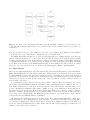
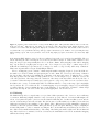
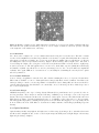
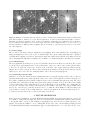
Figure 5. Variation of the field rotation for the North Ecliptic Pole which is continuously visible by Spitzer. The fields
of view are as identified in Figure 4. The leftmost panel is the orientation of the IRAC fields of view on 01 June 2004, the
middle panel displays the orientation of the FOVs on 01 September 2004 and the rightmost panel displays the orientation
on 01 December 2004.
A variety of dither patterns are available in full array mode, 12 and 36 point Reuleaux triangle, 5 point
Gaussian, 9 point random (points drawn from a uniform distribution), 16 point spiral and cycling. The spiral
pattern was designed for IRAC to be compact but also have a good figure of merit 9 for self-calibration. The
Reuleaux patterns are also well suited for observers who are considering self-calibrating their images ∗∗ . The
random and spiral patterns are the optimum size for 1/3 and 1/4 subpixel dithering. The cycling dither pattern
allows observers to specify a pattern of any desired depth. The pattern has 311 independent positions with each
set of four consecutive dithers providing complete 1/2 pixel sampling. When used with mapping, the cycling
dither pattern will provide a different dither position for each map center even if the dither pattern has a depth
of one. The subarray mode has only two options, a four point pattern drawn from a Gaussian distribution and
a nine point Reuleaux triangle.
3. OVERVIEW OF DATA REDUCTION PIPELINE
The IRAC pipeline at the SSC produces two sets of data products from the raw data. The basic calibrated data
(BCDs) are the raw data frames processed for bias (dark) offsets, pixel to pixel gain variations, nonlinearity and
other instrumental signatures. Section 3.1 describes the data products derived from the BCDs. A more complete
description of the IRAC pipeline is available in the IRAC Pipeline Description Document available at the SSC
website. A separate processing pipeline, SIP10 , was created by the IRAC instrument team†† . While SIP uses
the same algorithms as the official IRAC pipeline, it was written independently and is used for validation and
code development purposes.
Three of the pipeline operations, dark offset subtraction, flat fielding and absolute calibration, require inputs
derived from on-orbit calibration observations which are conducted every IRAC observing campaign. The dark
offset is derived from well dithered observations of a low background (high Ecliptic latitude) region for each
frametime. The dark data are median stacked with outlier rejection and object masking to create dark frames.
The flat fields are also derived from sky data; in this case, well dithered 100s frametimes of the Zodiacal light
are used to generate the flatfield. Science observations are processed with the flat field and dark frame that are
nearest in time to the observation and validated by the IRAC IST. The flux calibration for IRAC is derived from
observations of ten primary calibrators at the beginning and end of each campaign. A scaling factor between
DN/s and MJy/sr for each IRAC channel is determined by comparing the measured flux of each calibrator with
∗∗
The SSC does not currently support the self-calibration method of data reduction.
The instrument team at the Smithsonian Astrophysical Observatory oversaw the design and development of IRAC,
which was built at NASA Goddard Space Flight Center. Responsibility for the day to day operation of IRAC transferred
to the IRAC instrument support team (IST) at the SSC at the end of the in-orbit checkout. The teams continue to work
collaboratively to improve the performance of the instrument.
††