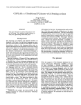
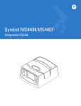
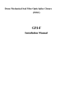
1
SMS Controller
2x2
User Manual
2 Digital Inputs
2 Open-Collector Outputs
Monitoring
Control
Event Logging
SMS and Email Alarming
Remote Configuration
advanced information networks
Ph: +64 3 366 1426
PO Box 40031
Christchurch
NEW ZEALAND
www.advancedinformation.net
IMPORTANT INFORMATION
It is important that you read this manual thoroughly before using your Live-Link SMS Controller.
Record the following Information as you will need it when updating your unit or making support inquiries:
RECORD YOUR PRODUCT AND CLIENT AREA DETAILS HERE
Live-Link Phone Number:
Live-Link IMEI Number:
Client Area Web Address:
www.advancedinformation.net/xe7000/
Client Area Login Username:
Client Area Login Password:
SMS Command Quick Reference:
?
STATUS
1 ON
1 OFF
2 ON
2 OFF
RESET
Get System Status
Get System Status
Turn on Output 1
Turn off Output 1
Turn on Output 2
Turn off Output 2
Reset the device.
(see section 8.3).
(see section 8.3).
(see section 4.3).
(see section 4.3).
(see section 4.3).
(see section 4.3).
(see section 8.4).
Live-Link SMS Controller Quick Reference Card
Site: _________________
Complete this business card sized reference card,
photocopy it and give it to your team so they can
each carry a copy in their wallet.
Ph No: _________________
SMS Commands:
?
Get System Status
1 ON
Turn Output 1 On
1 OFF
Turn Output 1 Off
2 ON
Turn Output 2 On
2 OFF
Turn Output 2 Off
RESET
Reset the Device
www.advancedinformation.net/live-link/
Contact your local distributor for all support inquiries:
Advanced Information Networks Ltd
PO Box 40031
Christchurch
NEW ZEALAND
Ph:
+64 3 366 1426
Email:
[email protected]
Live-Link SMS Controller User Manual – Preliminary 1
Copyright © 2011 Advanced Information Networks Ltd, All Rights Reserved.
2
CONTENTS
OVERVIEW
Specifications
Understanding Information Flow
4
GETTING STARTED
Connect
Configure
Commission
Communicate
5
INPUTS
Input Connectors
Input LEDs
Debounce
Input Configuration
Input Change Event
Input Information in Status Messages
Testing the Inputs
11
11
11
12
12
12
12
12
OUTPUTS
Open-Collector Output Driver
Output Connectors
Controlling Outputs with Text Messages
Output LEDs
Output Configuration
Reset State
Output Event Logging
Output Information in Status Messages
13
13
13
14
14
14
14
15
15
POWER SUPPLY
Power Connectors
Power Supply Monitoring
CELLULAR CONNECTIVITY
SIM Card
SIM PIN Number
Cellular Network Access
Fitting the SIM Card
Service Center Number
Cellular Antenna Connector
Cell LED
Cell Activity
What can go Wrong?
Radio Link
SIM Card
No GPRS Connection
No Web Server Connection
18
18
18
18
WEB SERVER
20
Configuration
20
Online Configuration Tools
Adding your SMS Controller to your Online Account
Configuring your SMS Controller Online
Event Logging
20
Real Time Clock
21
Watchdog
21
Firmware Upgrades
21
TEXT MESSAGING
Alarm Messages
Controlling Outputs
Status Text Messages
Reset Command
Unknown Commands
Text Messages from Unauthorised Users
22
22
22
22
22
22
22
TROUBLE SHOOTING AND FAQS
No reply to Status Query
Alarm message are taking a long time.
Do I need to acknowledge alarms?
The SMS Controller is not going on-line.
23
16
16
16
17
17
WARRANTY
24
TERMS AND CONDITIONS
25
DOCUMENT HISTORY
26
Live-Link SMS Controller User Manual – Preliminary 1
Copyright © 2011 Advanced Information Networks Ltd, All Rights Reserved.
3
1 OVERVIEW
The Live-Link SMS Controller is a versatile monitoring and control device that can be used in a wide range of
applications. It is remotely configured over from a central web site, which also provides a watchdog service to ensure
that each device make regular contact.
1.1.1
•
•
•
•
•
•
•
•
•
•
1.1.2
Specifications
Power Supply:
Current Consumption:
Digital Inputs:
Outputs:
Wireless Connectivity:
Cellular Antenna Connector:
EMC Compliance:
Temperature Range:
Weight:
Size:
9-42 V DC.
40mA at 12V Idle.
2x Digital Inputs with Internal Pullups.
2x Open-Collector Outputs. Rated to 42V / 300mA.
GPRS / GSM.
SMA.
AS/NZS CISPIR22: 2002 Class B and FCC 47 Part 15: 2001 Class B.
TBD.
TBD.
109.79 x 90.79 x 37.20mm
Understanding Information Flow
The following diagram provides a simplified overview of the information flow within the Live-Link SMS Controller
System:
Users
Inputs Changed
Outputs Changed
PSU Monitor
SMS
email
SMS Controller
Events
GP
RS
Advanced
Information
Networks
Web Server
Information Flow within the Live-Link SMS Controller System
Live-Link SMS Controller User Manual – Preliminary 1
Copyright © 2011 Advanced Information Networks Ltd, All Rights Reserved.
4
2 GETTING STARTED
CONNECT
CONFIGURE
COMMISSION
COMMUNICATE
Sensors to Digital Inputs
Loads to Outputs
Fit SIM Card
Fit GSM Antenna
Connect Power Supply
Online Registration
Site Configuration
Setup Phonebook
Setup Event Log Email List
I/O Configuration
Testing Cellular Connectivity
Test Inputs and Sensors
Test Outputs
Test PSU Monitoring
Testing Event Logging
Specify Maintenance Cycles
Documentation
Receive Event SMS Messages
Receive Email Messages
Control Outputs
Query the Status
Review Event Logs
Backup Logged Data
Routine Maintenance
Maintain the Phone Book
Live-Link SMS Controller User Manual – Preliminary 1
Copyright © 2011 Advanced Information Networks Ltd, All Rights Reserved.
5
Connect
CONNECT
Test Button
Terminal
Block
SIM Card
Holder
Location of key parts inside the SMS Controller
Typical Live-Link Integration Diagram
Example Cabling
Live-Link SMS Controller User Manual – Preliminary 1
Copyright © 2011 Advanced Information Networks Ltd, All Rights Reserved.
6
Mechanical Drawing (mm)
See Section 3.1 for Connecting Inputs.
See Section 4.1 for Connecting Outputs.
See Section 6.2 for Antenna Connection.
Live-Link SMS Controller User Manual – Preliminary 1
Copyright © 2011 Advanced Information Networks Ltd, All Rights Reserved.
7
Configure
CONFIGURE
Each Live-Link SMS Controller is configured in the client area of the Advanced Information Networks web site.
Therefore the first stage of configuration is to setup your user account, and then to add the SMS Controller to that
account.
Online Registration
Contact Advanced Information Networks for your username and
password.
See Section 7.1
Then you can login to the client area of the Advanced
Information Networks web site:
http://www.advancedinformation.net/xe7000/
Once inside the client area, you will see the Dashboard which
lists all your devices.
Go to the Add Unit page to add your SMS Controller to your
account so that you can configure it.
The web server uses the IMEI number to identify each device.
Site Configuration
Units that have been added to your account can be configured
on the Edit Details page.
See Section 7.1
Setup Phonebook
Only predefined users can receive alarm messages from the
SMS Controller and control its outputs. These users are stored
in the phone book of the SMS Controller, which is maintained
online. You will need to the add name, cell phone number, and
email address of each user.
See Section 7.1
The phone book can be found on the Edit Details page.
Setup Event Log Email List
Events can be send to a number of email addresses.
See Section 7.1
The email list can be found on the Edit Details page.
I/O Configuration
Various settings for the inputs and outputs can be configured on
the the Edit Details page.
See Sections 3.4
and 4.5
Testing Cellular
Connectivity
A SIM Card that is known to be working should be fitted to the
SMS Controller. Press the button until the details of the cellular
connection are shown on the display.
See Section 6.1
Live-Link SMS Controller User Manual – Preliminary 1
Copyright © 2011 Advanced Information Networks Ltd, All Rights Reserved.
8
Commission
COMMISSION
Now that the SMS Controller has been configured it must be tested and documented before it is put into active
service.
Test Inputs and Sensors
The LEDs on the front panel of the SMS Controller show the
status of each input. Note that they will flash during the
debounce time while it waits for the input to settle in a new
state.
See Section 3.2
Test Outputs
Send SMS commands to the SMS Controller to turn the outputs
on and off.
See Section 4.3
Test Power Supply
Monitoring
Adjust the power supply voltage to check the low power alarm.
(You may have to do this test on the bench, rather than in the
field.)
See Section 5.2
Test Event Logging
Check that you have received the following:
• Correct text messages
• Correct logs on the web server (see the Event History
page)
• Correct emails
See Section 7.2
Specify Maintenance
Cycles
It is the users responsibility to specify and carry out
maintenance and calibration cycles that are appropriate for their
specific equipment and application.
Documentation
It is good practice to document the system, the organisations,
and personnel involved with each site that is commissioned.
Live-Link SMS Controller User Manual – Preliminary 1
Copyright © 2011 Advanced Information Networks Ltd, All Rights Reserved.
9
Communicate
COMMUNICATE
Once in active service the system will have the following activities:
Receive Alarm Messages
Users will receive alarm messages when:
The device is reset,
An Input Changes,
An Output is Changed,
Power gets low, or returns to a safe level.
See Section 8.1
Alarms are only sent once and do not need to be acknowledged
by reply SMS.
Control Outputs
Users can turn power to the loads on and off using text
messages.
See Section 4.3
Query the Status
A user can request the status of the system by sending it a text
message. It will reply with a status text message.
See
Section
Error: Reference
source not found
Review Event Logs
The system administrator should review the logged data at a
frequency that is suitable for the application.
See Section 7.2
Backup Logged Data
It is the responsibility of the system administrator to periodically
back up data that is logged to the Advanced Information
Networks web server.
Routine Maintenance
During commissioning the system integrator may have specified
routine maintenance and calibration procedures that need to be
undertaken.
Maintain the Phone Book
From time to time the users of the system will change. The
configuration is easily updated via the Advanced Information
Networks client area.
Live-Link SMS Controller User Manual – Preliminary 1
Copyright © 2011 Advanced Information Networks Ltd, All Rights Reserved.
See
7.1.3
Section
10
3 INPUTS
The Live-Link SMS Controller features 2 voltage-free, clean-contact sensor inputs that can be can be connected to
security switches, wet floor sensors, tamper switches, door switches etc. The inputs detect when a set of connected
contacts are open or closed. Each sensor is connected to an input pin and a COM pin. The COM pins are all
connected together. Do not assume that the COM pins are connected to Earth – this depends on your power supply
arrangement.
Digital Input
External Sensor Switch Contacts
Pullup
SENSOR INPUT
CONTACT
COM
CONTACT
Sensor Connection
3.1 Input Connectors
The input terminals are the lower 3 positions of the main
terminal block. They are labeled COM, IN1 and IN2.
3.2 Input LEDs
The red Input LEDs show the state of each of the inputs:
ON
OFF
FLASHING
Input is high voltage (or open circuit).
Input has been connected to COM (closed circuit).
The input has recently changed, and is being debounced,
ie: waiting for stability.
Live-Link SMS Controller User Manual – Preliminary 1
Copyright © 2011 Advanced Information Networks Ltd, All Rights Reserved.
11
3.3 Debounce
When a switch opens or closes, there is usually some bounce or chatter associated with the
mechanical movement of contacts. This is know as switch bounce, and applies to mechanical
switches, relays, reed switches etc.
Also, sensors in some applications may be measuring things that do not have a smooth transition
from one state to another. For example, a level sensor in a water tank that is being filled may
chatter on the waves as the level moves up past the sensor position.
To provide stability for both of these scenarios, the Live-Link SMS Controller will not accept an
input change event unless the input has been in the new state continuously for at set period of
time. This is call the debounce time, and it is fixed at 5 seconds.
When an input changes state, it's associated LED will start flashing until the debounce period has
filtered any noise and the input has been stable for a set period of time. If the input settles in the
original state, no input event is generated. So for example, when a 2 second pulse (closed –
open – closed) occurs, the LED will flash until it settles in the closed state for 5 seconds, and no
input change will be registered.
3.4 Input Configuration
The inputs are configured online. Your devices appears in the online dashboard, and for each
one there is an “edit details” page that allows you to configure the following messages for the
inputs:
Digital Input 1 Low Message
Digital Input 1 High Message
Digital Input 2 Low Message
Digital Input 2 High Message
On start up the Live-Link will send Power-Up Status SMS messages show the state of each input
and output.
3.5 Input Change Event
Whenever an input changes state (and has been duly debounced), a number of things happen:
1. All the users in the phone book are sent a text message showing the new input status.
2. The SMS Controller contacts the Web Server to log the Input Change Event.
3. The Web Server sends emails to the list of email addresses notifying people of the Input Change
Event.
3.6 Input Information in Status Messages
Both inputs are reported in the status message.
3.7 Testing the Inputs
During testing take care to exercise the sensors, not the input pins directly. Check that the states
of the inputs are showing as expected on the LEDs, and in the status reply messages to the query
SMS command.
While exercising the inputs, check that the Alarm Notifications are correct.
Check the event logs on the web site.
Live-Link SMS Controller User Manual – Preliminary 1
Copyright © 2011 Advanced Information Networks Ltd, All Rights Reserved.
12
4 OUTPUTS
4.1 Open-Collector Output Driver
The Live-Link 2x2 SMS Controller features open-collector type outputs that pull the output
terminal to COM when activated.
Output Driver
PWR
Load
O1
Power Supply
COM
+
-
Non-Inductive Load Connection
IMPORTANT
Inductive loads must have commutating diodes connected at the load. Failure to properly
commutate an inductive load may cause damage to the SMS Controller. This type of damage will
not be covered the warranty.
The output transistor is rated at 300mA continuous.
The default or reset state of the outputs is OFF.
4.2 Output Connectors
The output terminals are in the middle of the main terminal
block. They are labeled O1 and O2.
Live-Link SMS Controller User Manual – Preliminary 1
Copyright © 2011 Advanced Information Networks Ltd, All Rights Reserved.
13
4.3 Controlling Outputs with Text Messages
Outputs are controlled by text messages. The following commands can be used:
1 ON
1 OFF
2 ON
2 OFF
Note: These commands are not case sensitive.
When a valid command has been received, the change in output will be sent to all users in the
phone book, including the phone number of the user that changed the output.
Security is implemented with Caller ID. Any SMS messages from cell phone numbers that are not
in the phone book are ignored. PIN numbers are not used for security. If there is any doubt about
the security of a users cell phone, remove that user from the phone book and reconfigure the
unit.
If the SMS Controller receives an invalid command from someone in the phone book, they will be
sent a text message with a list of valid commands.
Text messages from people who are not in the phone book are logged to the web server and then
ignored.
4.4 Output LEDs
The red Output LEDs show the state of each of the outputs:
OFF
ON
Output off.
Output on. Open-collector driver connects the output to COM.
4.5 Output Configuration
The outputs are configured online. Your devices appears in the online dashboard, and for each
one there is an “edit details” page that allows you to name the outputs:
Output 1 Name
Output 2 Name
These names are used in the text messages.
4.6 Reset State
IMPORTANT
The outputs are turned OFF whenever the SMS Controller is powered up, or reset.
On reset the Live-Link will send Power-Up Status SMS messages show the state of each input
and output. Take care to check the status of the outputs as you will need to manually turn them
on if they are not in the state that you want them.
Live-Link SMS Controller User Manual – Preliminary 1
Copyright © 2011 Advanced Information Networks Ltd, All Rights Reserved.
14
4.7 Output Event Logging
All output change events are logged to the Web Server, including the phone number of the
person that changed the output.
4.8 Output Information in Status Messages
Both outputs are reported in the status message.
Live-Link SMS Controller User Manual – Preliminary 1
Copyright © 2011 Advanced Information Networks Ltd, All Rights Reserved.
15
5 POWER SUPPLY
The Live-Link SMS Controller will operate from 9-42VDC.
5.1 Power Connectors
The power supply terminals are the upper 2 positions of the
main terminal block. They are labeled COM and PWR.
PWR is the positive terminal, COM is negative.
5.2 Power Supply Monitoring
The power supply is monitored. The set-point is predefined at 11.0V. If the supply drops below
this level, all the users will receive a text message. A “Return to Normal” message is generated
when the voltage rises above 12.0V.
The SMS Controller averages the power supply voltage over a 5 second window. This reduces its
susceptibility to noise and spikes. It does mean that by the time an alarm is generated, the
voltage will have moved past the set point.
Power supply information is included in the status text messages.
Live-Link SMS Controller User Manual – Preliminary 1
Copyright © 2011 Advanced Information Networks Ltd, All Rights Reserved.
16
6 CELLULAR CONNECTIVITY
6.1 SIM Card
Your Live-Link SMS Controller will need a SIM Card to access the Cellular Network. To make changes to the SIM Card
settings, put it into a mobile phone that operates on the same network, and use its menu system to change settings
as required. As the menu systems of each mobile phone are very different, please refer to the mobile phone
documentation for more information.
6.1.1
SIM PIN Number
IMPORTANT
Before inserting the SIM Card into the SMS Controller, the SIM Card PIN must be disabled.
SIM Cards are protected with PIN numbers to avoid unauthorised use in case it is lost or stolen.
The PIN number protection can be enabled or disabled with the SIM Card Lock. This is a setting
on the SIM Card that you can change by putting it into a Cellular mobile phone and using its
menu system to change settings as required.
New SIM Cards from Vodafone New Zealand usually come with the SIM Card Lock disabled by
default, so you may be able to use it straight away.
6.1.2
Cellular Network Access
The SIM Card must be recognised and activated by the Cellular Network of your choice.
Test the SIM Card in a cell phone before fitting it to the SMS Controller.
The type of connection plan that you use must support both SMS messaging and mobile data. If
you use a pre-pay plan, ensure that you are in credit.
The Live-Link should be used in an area that has sufficient Cellular Network Coverage.
6.1.3
Fitting the SIM Card
Ensure the the SMS Controller is switched off when fitting the SIM Card into its holder.
6.1.4
Service Center Number
To send SMS messages the SIM card must be setup with the correct Service Center Number for
the Cellular Network provider that you use. Your SIM card will probably come with this number
preset to the correct number.
The Service Center Number for Vodafone New Zealand, is +6421600600.
If you are using the Live-Link SMS Controller in another country and/or you can not send text
messages, check the Service Center Number. To do this, place your SIM Card into a suitable
mobile phone and follow the phone’s menu system. For more information, contact the Customer
Services Department of your Cellular Network provider.
Live-Link SMS Controller User Manual – Preliminary 1
Copyright © 2011 Advanced Information Networks Ltd, All Rights Reserved.
17
6.2 Cellular Antenna Connector
The SMA type Cellular Antenna Connector is located on the top of the LiveLink SMS Controller. Use an antenna that is suitable for your location.
During commissioning, press the Test Button inside the SMS Controller to
generate a text message that shows RSSI and BER.
RSSI (Received Signal Strength Indicator) of 6 or above is usually
high enough for reliable operation.
BER (Bit Error Rate) should be less than 5.
RSSI and BER are logged to the Web Server, so you can keep track of
network communication levels.
6.3 Cell LED
The green Cell LED shows the state of the cellular network connectivity with a number of flash patterns:
Establishing GPRS Connection (Off, Flashing On)
Online, but IDLE (On, Blinking Off)
Online, and communicating with Web Server (Fast Flash)
6.4 Cell Activity
When the SMS Controller starts up, it attempts to create a GPRS connection. The Cell LED will be off most of the time,
and flash on periodically. This usually takes less than 30 seconds.
Once a GPRS connection has been established, the LED will be on, and blink off periodically.
Whenever an event occurs, the SMS Controller will connect to the Advanced Information Networks web server, to
register the event, get the the latest configuration, and get the current date and time. When it is communicating with
the web server the LED will flash quickly.
6.5 What can go Wrong?
This system relies on a number of things, all of which must be working for correct operation:
•
•
•
An acceptable radio link to the cellular network.
A valid and operational SIM card with sufficient credit.
An internet connection to the Advanced Information Networks web Server.
6.5.1
Radio Link
Make sure you can operate your cell phone (assuming it is on the same network), in the same
area as the SMS Controller is situated. See Section 6.5.1 above more more details.
Be aware that cellular networks can on rare occasions, drop out from time to time. Contact your
cellular network provider to see if there are any known issues. If your system is mobile, then
there may be times when you are outside the coverage area.
Live-Link SMS Controller User Manual – Preliminary 1
Copyright © 2011 Advanced Information Networks Ltd, All Rights Reserved.
18
During commissioning you can press the Test button inside the SMS Controller and it will send
you RSSI and BER information.
6.5.2
SIM Card
Ensure there is no PIN number on your SIM Card, that it has been activated, and that it has
sufficient credit. SIM Cards do fail sometimes. A simple test for all of these scenarios is to test it
in your phone.
6.5.3
No GPRS Connection
The SMS Controller can send and receive text messages when is no GPRS connection. If the LED
shows that it is trying to get a GPRS connection, send it the query text message: STATUS, to see if
you get a reply. If you do, you can be sure that you are registered on the cellular network.
Note that the SMS Controller gets its configuration from the Advanced Information Networks web
server, so your cell phone will not be in the phone book until it has been successfully configured.
This means that you have to get a good configuration before the above text messaging test will
work.
If the SMS Controller does not have a GPRS connection for more than 20 minutes, it will reset
itself to try remedy the problem.
6.5.4
No Web Server Connection
There are many steps in the internet connection between the SMS Controller and the Advanced
Information Networks web server. Any one of these step could have an issue that causes a loss
of communication to the server.
The web server itself may be down for maintenance of some kind. We will make every attempt to
give prior warning of any known outages.
A simple test it to see if you can access the server from your PC.
Once the SMS Controller has a configuration from the Advanced Information Networks web
server, it will save it. This means that text messaging will work after a reset even if there are
difficulties with a connection to the web server.
The SMS Controller will queue the last 10 events and log them to the web server as soon as it
gets a connection.
Live-Link SMS Controller User Manual – Preliminary 1
Copyright © 2011 Advanced Information Networks Ltd, All Rights Reserved.
19
7 WEB SERVER
7.1 Configuration
7.1.1
Online Configuration Tools
The Internet is used to remotely configure the SMS Controller. Use a web browser to log into the
client area of the Advanced Information Networks web site to configure the system.
System
Integrator's
PC / Laptop
Web browser
Advanced
Information
Networks
Web Server
GPRS
Live-Link
SMS Controller
SMS Controller Configuration Data-flow Diagram
The Live-Link connects to the Advanced Information Networks web server periodically to send
new event data, and to check for a new configuration. If a new configuration is available, it will be
downloaded and activated. If not, the periodic connection will be logged at the server as a
heartbeat so that the users can see that system is regularly communicating.
Once the system is up and running the need for reconfiguration is infrequent, and usually done
remotely. For example the phone book may need to be updated with staff changes.
7.1.2
1.
Adding your SMS Controller to your Online Account
Connect your PC to the Internet and go to the following address with your Web Browser:
www.advancedinformation.net/xe7000/
2. Assign your new Live-Link to an existing account:
Login to the Client Area with your existing username and password
Click on the Add Unit page
Setup the new unit. You will need the IMEI number from the SMS Controller
7.1.3
Configuring your SMS Controller Online
Once inside the client area you will see the dashboard which lists all the devices that you have in
your account, and some key information about each one.
7.2 Event Logging
Logging of data directly to the Internet provides a new level of Real Time data monitoring for telemetry applications. It
is often cheaper to log directly to the Internet than it is to travel to the site to download data from the Internal
Memory.
Live-Link SMS Controller User Manual – Preliminary 1
Copyright © 2011 Advanced Information Networks Ltd, All Rights Reserved.
20
Data is logged directly to the Advanced Information Networks web server.
To log data to the Advanced Information Networks web server you must pay a monthly fee. This data is downloaded
from the Client Area of the Advanced Information Networks web site.
7.3 Real Time Clock
The Real Time Clock (RTC) provides date and time information for the system. Data logging scan and log times are
based on the RTC. Outgoing alarm and status messages, and logged data are date and time stamped.
Whenever the SMS Controller contacts the server it gets updates its RTC.
7.4 Watchdog
The web server runs a watchdog timer on each device. If is has not heard from a device within a certain timeframe, it
will send text messages to the users to let them know that there may be an issue with this site.
7.5 Firmware Upgrades
Firmware upgrades can be done remotely over-the-air.
They are managed by Advanced Information Networks Ltd.
Live-Link SMS Controller User Manual – Preliminary 1
Copyright © 2011 Advanced Information Networks Ltd, All Rights Reserved.
21
8 TEXT MESSAGING
Users interact with the Live-Link SMS Controller using text messages. The SMS Controller sends Alarm Messages to
users when something changes state, and the users can send a can send text message to it to turn an output on or
off, or just to query the status of the system.
8.1 Alarm Messages
Alarm Messages can be generated when the state of an input changes between alarm or normal, when an output is
changed, or when there is a change in the state of the power supply.
SMS alarm messages are sent to all the users in the phone book.
8.2 Controlling Outputs
See Section 4.3.
8.3 Status Text Messages
To query the status of the system (the equipment being monitored and controlled), send ? or STATUS as an SMS
message from your mobile phone to the SMS Controller.
It will reply with a return text message containing details on the inputs, outputs, and power supply.
8.4 Reset Command
The SMS Controller can be remotely reset by sending RESET as a text message. When this is received, all users are
notified that the system will be reset (and who sent the command), and then 30 seconds later the system will restart.
Note that outputs that were on will be switched off.
8.5 Unknown Commands
If the SMS Controller receives an unrecognised text message command from a user who is in the phone book, it
replies showing a list of valid commands.
8.6 Text Messages from Unauthorised Users
Test messages received from users who are not in the phone book are logged to the web server, and then ignored.
Live-Link SMS Controller User Manual – Preliminary 1
Copyright © 2011 Advanced Information Networks Ltd, All Rights Reserved.
22
9 TROUBLE SHOOTING AND FAQS
No reply to Status Query
When I query the status of the SMS Controller by sending it a text message with ? or STATUS, I do not get a reply.
Is the power turned on? Is there someone on site that can verify this for you?
Make sure the SIM card is active and in credit if on a prepay account.
Ensure that you are sending the device query to the correct phone number.
Check that you are sending the correct command to the SMS Controller: ? or STATUS
Does the Cellular Modem has sufficient signal strength? Check the antenna and the Antenna Cable. Are there
any Cellular Network problems?
The number of the mobile phone you are using must be in the Phonebook of the SMS Controller.
Alarm message are taking a long time.
The Cellular Network can take some time to pass an SMS message from one mobile to another. Contact your
Cellular Network provider if you experience consistently long delays.
Does the Cellular Modem has sufficient signal strength? Check the antenna and the Antenna Cable. Are there
any Cellular Network problems?
Do I need to acknowledge alarms?
No. Alarm messages are sent only once when the event occurs.
The SMS Controller is not going on-line.
The SMS Controller must be able to access the internet so that it can download its configuration from the
Advanced Information Networks web server.
Live-Link SMS Controller User Manual – Preliminary 1
Copyright © 2011 Advanced Information Networks Ltd, All Rights Reserved.
23
10 WARRANTY
This product is guaranteed by Advanced Information Networks Limited to be free of manufacturing defects or faulty
materials, for a period of twelve months from the date of invoice.
This warranty covers the repair or replacement of goods returned to Advanced Information Networks Limited.
Expenses incurred in returning the Live-Link SMS Controller are not included.
Exclusions:
Damage that has been caused to the outputs by inductive loads.
Water damage. While the case is rated for outdoor use, the sealing of case and cables in their glands is
responsibility of the user.
Normal wear and tear.
Goods may be repaired or replaced at Advanced Information Networks Limited’s discretion. Repairs by parties other
than Advanced Information Networks Limited during the warranty period will not be reimbursed and will end the
warranty agreement.
This warranty extends to the repair of the Live-Link SMS Controller only and does not cover consequential damage or
damage to itself or faulty operation due to poor installation, incorrect programming, use of incompatible peripherals,
mechanical or electrical abuse, sustained shipping damage, use in unsuitable mechanical or electrical environments,
or Acts of God.
Please contact Advanced Information Networks Customer Service to obtain a Returned Materials Authorisation (RMA)
prior to shipping any products for repair. All shipments must be shipped prepaid and include proof of the date of your
original purchase. Please include your name, address, phone number, email address and a brief description of the
problem.
Live-Link SMS Controller User Manual – Preliminary 1
Copyright © 2011 Advanced Information Networks Ltd, All Rights Reserved.
24
11 TERMS AND CONDITIONS
By using Advanced Information Networks Limited's products you agree to be bound to the following terms and
conditions:
1. Advanced Information Networks Limited makes no representations or warranties with respect to the
accuracy or completeness of the contents of this publication and reserves the right to make changes to
specifications and product descriptions at any time without notice.
2. All title and copyrights in and to Advanced Information Networks Limited's products (including but not limited
to any images, photographs, text, web pages, web applications, software, firmware, circuit design,
mechanical design) and the accompanying printed materials, and any copies of software products, are
owned by Advanced Information Networks Limited or its suppliers.
3. Advanced Information Networks Limited (or related companies) assumes no liability whatsoever, and
disclaims any express or implied warranty relating to its products, including, but not limited to, the implied
warranty of merchantability, fitness for a particular purpose, or infringement of any intellectual property right.
4. Advanced Information Networks Limited (or related companies) will not in any circumstances be liable for
any damages whatsoever (including, without limitation, damages for loss of business, business interruption,
loss of business information, or any other indirect or consequential loss) arising out of, the use or inability to
use, supply or non-supply of its products or services, loss or theft of logged data, or transmission of any
computer virus.
5. Fees for Datalogging to the Advanced Information Networks web server must be paid in monthly advance.
Datalogging will cease on the first day of the month not paid in advance. A reconnection fee may apply. If the
account is not settled in full within 30 days, all previously logged data will be permanently removed.
6. Where Advanced Information Networks supplies SIM cards with the SMS Controller, you agree to be bound to
the terms and conditions of the Cellular Network Provider of that SIM card, and agree to indemnify Advanced
Information Networks from any unauthorised use.
7. The products described in this document are not designed, intended, authorised, or warranted for use as
components in applications intended to support or sustain life, or where malfunction of Advanced
Information Networks Limited’s product may result in direct physical harm, injury, or death to a person or
severe property or environmental damage. Advanced Information Networks Limited will pass on user
information and data to law enforcement agencies if there is any question of unauthorised use.
8. Advanced Information Networks Limited reserves the right to discontinue or make changes to its products at
any time without notice.
9. This agreement is governed by the laws of New Zealand.
Live-Link SMS Controller User Manual – Preliminary 1
Copyright © 2011 Advanced Information Networks Ltd, All Rights Reserved.
25
12 DOCUMENT HISTORY
Revision
Date
Author
Preliminary 1
01/08/11
GPJ
Notes
Preliminary release for review. All details subject to change.
Live-Link SMS Controller User Manual – Preliminary 1
Copyright © 2011 Advanced Information Networks Ltd, All Rights Reserved.
26