Download NodeLinke Users Guide

Transcript
NODELINK
Version 2.6
Data Management Software
USER'S GUIDE
April 2005
DRANETZ-BMI
1000 New Durham Road
Edison, NJ 08818-4019
Tel (732) 287-3680
Fax (732) 248-1834
Part Number UG-NODELINK
NODELINK Data Management Software
Published by Dranetz-BMI
1000 New Durham Road
Edison, New Jersey 08818-4019 USA
Telephone: 1-800-372-6832 or 732-287-3680
Fax: 732-248-1834
Web site: www.dranetz-bmi.com
Copyright 2005 Dranetz-BMI
All rights reserved
Printed in the United States of America
P/N UG-NODELINK Rev. G
2
User's Guide
Statement and Notices
Notice regarding proprietary rights
By accepting and using this manual, the user agrees that the information contained
herein will be used solely for the purpose of operating Dranetz-BMI equipment. This
publication is protected under the copyright laws of the United States Title 17 et seq.
Copyright
Dranetz-BMI NodeLink documentation and software are copyrighted with all rights
reserved. Under the copyright laws of the United States, neither the documentation nor
the software may be copied, photocopied, reproduced, translated, or reduced to any
electronic medium or machine readable form, in whole or in part, without the prior
consent of Dranetz-BMI except in the manner described in the following paragraph.
The recipient of the software hereby agrees that the proprietary information of the
program is privileged and amounts to a trade secret and that he or she will take
reasonable care not to disclose such information to any third parties, nor will he or she
transfer programs for consideration or otherwise to any third party. The recipient has the
right to make an archival copy and one working copy (for a total of two copies) of the
program for use on one machine forever. No other copies of the program can be made,
and no additional copies of the documentation can be made.
3
NODELINK Data Management Software
Statements and Notices, continued
Limitation of liability
Dranetz-BMI does not warrant that the software program will function properly in every
hardware/software environment. The software may not work in combination with
modified versions of the operating system, with certain print spooling or file facility
programs, or with certain computers or printers supplied by independent manufacturers.
Although Dranetz-BMI has tested the software and reviewed the documentation,
Dranetz-BMI makes no warranty or representation, either express or implied, with
respect to this software or documentation, including its quality, performance,
merchantability, or fitness for a particular purpose. Consequently, this software and
documentation are licensed as is, with the licensee assuming the entire risk as to their
quality and performance.
In no event will Dranetz-BMI be liable for direct, indirect, special, incidental, or
consequential damages arising out of the use or the inability to use the software or
documentation, even if advised of the possibility of such damages. In particular, DranetzBMI is not responsible for any costs including but not limited to those incurred as a result
of lost profits or revenue, loss of use of the computer program, loss of data, the cost of
substitute programs, or any claims by third parties.
Revision rights
Dranetz-BMI reserves the right to revise this publication from time to time and to make
changes in its content without any obligation of notifying previous users of such revisions
or changes.
Trademarks
NodeLink, InfoNode, DataNode, Signature System, PowerXplorer, PowerGuide,
NodeCenter and DranView are registered trademarks of Dranetz-BMI.
PQView is a registered trademark of Electrotek Concepts, Inc.
Microsoft (MS), Internet Explorer, Microsoft Windows, Windows 98, Windows 2000,
Windows XP, and Windows NT are registered trademarks of Microsoft Corporation.
4
User's Guide
Statements and Notices, continued
Statement of reliability
The information in this manual has been reviewed and is believed to be entirely reliable,
however, no responsibility is assumed for any inaccuracies. All material is for
informational purposes only and is subject to change without prior notice.
Statement of warranty
All products of Dranetz-BMI are warranted to the original purchaser against defective
material and workmanship for a period of one year from the date of delivery. DranetzBMI will repair or replace, at its option, all defective equipment that is returned, freight
prepaid, during the warranty period. There will be no charge for repair provided there is
no evidence that the equipment has been mishandled or abused. This warranty shall not
apply to any defects resulting from improper or inadequate maintenance, buyer-supplied
hardware/software interfacing, unauthorized modification or misuse of the equipment,
operation outside of environmental specifications, or improper site preparation or
maintenance.
5
NODELINK Data Management Software
TABLE OF CONTENTS
STATEMENTS AND NOTICE.................................................................................................................3
CHAPTER 1: PREPARATION FOR USE...............................................................................................7
NodeLink Software Package....................................................................................................................7
Computer Requirements..........................................................................................................................7
Introduction to NodeLink...........................................................................................................................8
Installing NodeLink...................................................................................................................................9
CHAPTER 2: BASIC OPERATION.......................................................................................................11
Common Screen Interface..............................………………………………….……………………………11
Navigation Bar..................................................................................................................………...........11
How to Add an InfoNode Site using Network (TCP\IP)...................................................……................15
How to Add an InfoNode Si te using Dial-Up Networking.......................................................……........17
How to Add a PX5 or 4400 Site using RS232 Serial Port Connection on your Computer..……............20
How to Add a PX5 or 4400 Site using Modem Connection on your Computer..………………………...23
Edit Site Properties............................................................…….........................................................26
Autopoll Schedule…...........................................................…….........................................................31
Tool Bar.................................................................................……................................………………..32
Status Bar.....................................................………...............................................................................32
Tree Directory.....................................................................……….........................................................33
Main Viewing Area.......................................................................……...................................................34
CHAPTER 3: QUICK REFERENCE GUIDE TO COLLECTING DATA................................................35
Getting Started...................................................................................…………………………................35
Downloading Data..............................................................................................................................……………………35
Viewing Data......................................................…….............................................................................36
CHAPTER 4: HOME PAGE...................................................................................................................37
Home Page..........…..…….....................................................................................................................37
CHAPTER 5: SITE STATUS PAGE......................................................................................................39
Site Status Page........……......................................................................................................……........39
Connecting to an InfoNode Site to Update Status........………................................................................39
Connecting to a PX5 or 4400 Site to Update Status.........………............................................................41
CHAPTER 6: INSTRUMENT STATUS PAGE......................................................................................45
Instrument Status Page...............................................................................................……….................45
Downloading Data from DataNode ...................................................................................……................45
PX5 or 4400 Data Options .....................................................................……..........................................47
Get Data: Download Event Data Files from PX5 or 4400 Data Card.....……..…...................................47
Values: Display Real-time Meter Data in NodeLink...........……..........................……............................50
Get Setup: Download Active Setups from PX5 or 4400 Memory...............................…….....................51
Monitor On/Off: Turn Data Monitoring On/Off……………...............................……................................52
Put Setup: Load Setup Changes from NodeLink to PX5 or 4400 Memory...........................…..............53
Set Time: Synchronize Time between Computer and PX5 or 4400.......................…............................54
Format Card: Format Data Card…………...………………………….......................................................55
CHAPTER 7: DOWNLOAD HISTORY PAGE........................................................................................57
Download History Page...................................................................………............................................57
Viewing Event Data from InfoNode Site...............................................……….......................................57
Viewing Event Data from PX5 or 4400 Site....................................……................................................59
APPENDIX A: PX5/4400 - NODELINK COMMUNICATIONS SETUP...................................................61
6
User's Guide
CHAPTER 1: PREPARATION FOR USE
NodeLink Software Package
Contents
One NodeLink software installation program on CD-ROM.
On-line documentation is included. Help topics can be printed, if desired.
NodeLink User's Guide, P/N UG-NODELINK, also included.
Customer Service
If any item is missing, or for installation or operating assistance with the NodeLink
software package, call Dranetz-BMI Customer Service at 1-800-372-6832 or (732) 2873680.
Computer Requirements
Computer
200MHZ+ Pentium or higher
Video adapter
1024 x 768 or better
Network
Ethernet 10BaseT or 100BaseTX using TCP/IP
Modem
56K
Memory
32MB RAM Minimum
Hard disk space
10MB free for the NodeLink program
500MB for data storage recommended
Operating system
Windows 98 SE, NT 4.0, 2000, or XP
Web browser
Internet Explorer V5.5 Minimum
Optional viewer
and data analysis
software
Dranetz-BMI DranView V5.10 or higher
Electrotek Concepts PQView V3.2 or higher
7
NODELINK Data Management Software
Introduction to NodeLink
NodeLink software is a Windows-based system that allows downloading, archiving and
visualization of event-type data from a variety of instruments including Dranetz-BMI
current and legacy products, Signature System InfoNode and DataNode,
PowerXplorer PX5 and PowerGuide 4400. NodeLink uses the InfoNode-DataNode,
PX5 or 4400 in conjunction with the DranView or PQView software to form a powerful
remote data management program.
Using NodeLink to Download InfoNode Data Files
NodeLink is used to retrieve data files stored in InfoNodes so that they can be archived
and/or viewed using viewer/analysis programs such as DranView or PQView. Data is
stored and viewed on a per DataNode basis. A web browser can be launched from
within NodeLink to view the InfoNode directly. NodeLink itself does not directly allow
users to change setups of the InfoNode or DataNode, nor does NodeLink display any
other views and reports in the InfoNode system.
Data downloads can be initiated manually or automatically using a scheduler built in to
the NodeLink. NodeLink supports the Signature System InfoNode, with the ability to
download data from various DataNodes such as EPQ 5520/5530, 5540, 5560 and 5571.
Using NodeLink to Download PX5 or 4400 Data Files
NodeLink V2.6 or higher is required to access event data and setups when using PX5 or
4400 firmware V1.10 or higher. The NodeLink application allows users to download data,
upload or download setup parameters, and view real time meter data from PX5 or 4400.
Users can change a select PX5 or 4400 measurement parameters i.e. circuit type or
monitoring mode, directly from NodeLink.
NodeLink communicates directly with the PX5 or 4400 using the Isolated
Communications Module assemblies. The module assemblies use either an RS232
serial port (P/N COMM-RS232), USB adapter (P/N COMM-OUA), or Modem/Ethernet
adapter (P/N COMM-OEA) to connect the PX5 or 4400 to a computer. Communications
modules use infrared light to transfer text and graphics to a computer running NodeLink.
For detailed information on how to install the communications modules to connect to
PX5 or 4400, refer to the Dranetz-BMI Information Sheet: PX5/4400 Communications
Modules, P/N 899120. Pertinent information can also be found in the PowerXplorer PX5
User's Guide (P/N UG-PX5) or PowerGuide 4400 User's Guide (P/N UG-4400).
About this Manual
This User's Guide provides instructions on how to install NodeLink, explains the main
pages and various navigational links found in NodeLink, and describes how to use
NodeLink to connect to and download data from the InfoNode, PX5 or 4400. Screen
user interface for NodeLink includes the following: Navigation Bar, Tool Bar, Status Bar,
Tree Directory, and Main Viewing Area. A quick guide to setting up NodeLink Groups/
Sites as well as downloading and viewing data can be found under Chapter 3, Quick
Reference Guide to Collecting Data.
8
User's Guide
Installing NodeLink
Follow these steps to install NodeLink:
1) Insert the NodeLink installation CD-ROM into the appropriate drive. The Autorun
feature should start the NodeLink installation program if this option is active on your
computer. In case the installation program does not start, proceed to Step 2.
2) From the Start menu select Run. Enter ”d:\NLsetup”, where d is the letter of the CD
drive. You may have to substitute the appropriate CD drive letter for your computer.
When done, click OK.
3) The NodeLink Setup Options screen will be displayed as follows.
Click Standard when using a modem connection to communicate with the Signature
System InfoNode. Proceed to Step 4.
Click Option 1 when not using a modem connection (e.g. using a computer network
card) to communicate with the InfoNode, PX5 or 4400. Proceed to Step 4.
Click Exit Setup to quit the Setup program. The Exit Setup dialog box will appear.
4) NodeLink prepares the Installation Wizard to guide users through the NodeLink
application setup. When done, NodeLink prompts users to select the destination
folder where the NodeLink program will be installed. Proceed to Step 5.
9
NODELINK Data Management Software
Installing NodeLink, continued
5) The Choose Destination Location screen provides information on the directory path
where the NodeLink application will be installed.
To use the default destination folder location, click Next and proceed to Step 6.
To change the destination folder location, click Browse then select the destination
path where NodeLink program will be installed. When done, click Next and proceed
to Step 6.
6) The Welcome screen will be displayed. Please read this screen then click Next to
continue.
7) The Select Program Folder screen will be displayed. The default folder is called
"Dranetz-BMI Power Suite”. If you would like to use a different folder name, enter it in
the Program Folder line. When done, click Next.
8) A Microsoft XML Parser Installation screen message is displayed. This message
appears whether or not the required minimum version of Internet Explorer is already
installed in your computer. The message underscores the web browser requirement
for the NodeLink program. Click OK to continue with the installation.
9) NodeLink will now be installed in your hard disk. Please follow any additional
instructions displayed by the installation program to complete the installation.
Once NodeLink installation is completed, the NodeLink icon will be added to the existing
Dranetz-BMI Power Suite program folder (if one does not already exist, a new folder will
be created). Double-click the NodeLink icon at any time to start the NodeLink
application.
10
User's Guide
CHAPTER 2: BASIC OPERATION
Common Screen Interface
NodeLink features a graphical user interface, employing pull down menus and point and
click icon buttons present in most Windows-based programs. The interface by which
users operate NodeLink is common across the different NodeLink pages and even when
viewing actual InfoNode pages. Some menu commands and/or icons are disabled
depending on which stage of operation the user is and which page is on active display in
the Main Viewing Area. The main parts of a NodeLink screen are described below.
Common screen interface available to all NodeLink pages are discussed in detail in this
chapter.
Navigation bar
Tool bar (p. 32)
Tree directory
consisting of
Groups and Sites
(p. 28)
Main viewing
area (p. 34)
Status bar
(p. 32)
Navigation Bar
The Navigation Bar has three text-based menus to choose from: File, Directory, and
Help. Menu items can be selected by pointing the mouse cursor over them and clicking
the left mouse button, or by pressing the <ALT> key and the underscored letter in the
text string simultaneously.
> File
File has three choices: Preferences, Data Folder and Exit. There is no File Save or Print
commands as these functions are handled within specific stages of operation of this
program, browser, or other analysis programs.
11
NODELINK Data Management Software
>> Preferences
The Preferences dialog box is used when multiple instrument types are installed
or added to the NodeLink, and/or when more than one compatible data viewer is
present. Preferences allow users to select which type of instrument or monitor is
the default, and/or which data viewer is the default. The Preference settings
apply to the Add Site and Viewer tool bar buttons.
>> Data Folder
The Data Folder is used to set the location of folder where downloaded data files
are stored. NodeLink will automatically store data in a default folder when there is
no specified data folder to store data in. Users are advised to get into the practice
of creating their own data folders before collecting data. This will facilitate
location of downloaded files and give users more control when downloading data.
NodeLink automatically maps out
the directory path for existing/
previously created data folder;
users are allowed to create their
own directory folder where
downloaded data files will be stored
>> Exit
Exit closes the NodeLink program, terminating any open communication links
and files.
12
User's Guide
> Directory
Directory contains the commands to do the following: create New Group, Add Site,
Delete, Edit Properties, and set Autopoll Schedule. A Site is the equivalent of a standalone instrument e.g. an InfoNode, PX5 or 4400. A Group consists of one or more Sites.
>> New Group
Select Directory > New Group or click the New Group icon on the tool bar to
create a new group entry in the tree directory. Enter the name for the new group
in the text box provided.
To change the Group name, simply click on the name and the text box will show
name in reverse video. Enter the new name in the text box provided.
To abort creating a new name, press <ESC>.
enter New
Group name
>> Add Site
Each Group consists of one or more Sites. A Site is an InfoNode, PX5 or 4400
that has stored data which users can download and save. The same Site can be
added to several Groups, however this would only create multiple files with
duplicate data.
To add a Site, click on Directory > Add Site or use the Add Site icon on the tool
bar. The Add Site command is enabled only after you have created and
highlighted a Group in the tree directory.
Select InfoNode or PX5 or 4400, depending on the type of site that you want to
add.
13
NODELINK Data Management Software
Screen below shows menu selections to add an InfoNode site. Proceed to page
15.
Screen below shows menu selections to add a PX5 or 4400 site. Proceed to
page 20.
14
User's Guide
How to Add an InfoNode Site using Network (TCP/IP)
1) Select a Group in which you want to add an InfoNode Site. Click Directory >
Add Site on the navigation bar or click the Add Site icon on the tool bar.
Select InfoNode if you want to add an InfoNode site.
Result: The following screen will appear.
NodeLink presents two options to access an InfoNode site. First option is
through Network (TCP/IP), those who use a network card to access the
InfoNode (discussed in this page). Second option is through Dial-Up
Networking, those who use a telephone line to access the InfoNode (discussed
in page 17).
2) Select Network (TCP/IP) when using a network card to access the InfoNode.
The default connection type is Network (TCP/IP). Click Next to continue.
Result: The following screen will appear.
15
NODELINK Data Management Software
How to Add an InfoNode Site using Network (TCP/IP), continued
3) Enter the IP address of the InfoNode you want to connect to. If the InfoNode
IP address is registered as a Domain Name, you can specify the Fully
Qualified Domain Name (FQDN) instead of the IP address. When done, click
Next.
Result: The following screen will appear.
4) Enter the required Site Name properties. When entering a local directory
name for InfoNode, use the following characters only: Alphanumeric,
Underscore, Hyphen. Using characters other than these may result in
NodeLink system error, particularly in Download History page. Also, to
successfully establish connection with the InfoNode, the User Name and
Password entered must match those used to log on to the Signature System
InfoNode. When done, click Next.
Result: The following screen will appear.
5) Click Finish to add Site. The name of the newly added InfoNode Site appears
under the respective Group in the tree directory.
16
User's Guide
How to Add an InfoNode Site using Dial-Up Networking
NOTE: Before you attempt to connect NodeLink to the InfoNode via Dial-Up
Networking, you must first be able to contact the InfoNode using your computer’s
dial-up capabilities. Refer to the Series 5500 InfoNode User's Guide, Chapter 2
Preparation for Use, for detailed information on InfoNode setup and
configuration. Part number for InfoNode User's Guide is UG-INODE5500.
1) Select a Group in which you want to add an InfoNode Site. Click Directory >
Add Site on the navigation bar or click the Add Site icon on the tool bar.
Select InfoNode if you want to add an InfoNode site.
Result: The following screen will appear.
2) Network (TCP/IP) has been chosen as default. Select Dial-Up Networking
when using a telephone line to access the InfoNode.
Result: The following screen will appear.
17
NODELINK Data Management Software
How to Add an InfoNode Site using Dial-Up Networking, continued
3) Enter the modem IP address of the InfoNode you want to contact. Then
highlight the name of the corresponding dial-up network to be used in the
connection in the list provided.
Result: The DialUp dialog box appears as follows.
Result: After entering items in the dialog box, click Next to proceed to the
Site Name screen below.
18
User's Guide
How to Add an InfoNode Site using Dial-Up Networking, continued
4) Enter the required Site Name properties. When entering a local directory
name for InfoNode, use the following characters only: Alphanumeric,
Underscore, Hyphen. Using characters other than these may result in
NodeLink system error, particularly in Download History page. Also, to
successfully establish connection with the InfoNode, the User Name and
Password entered must match those used to log on to the Signature System
InfoNode. When done, click Next.
Result: The following screen will appear.
5) Click Finish to add site. The name of the newly added InfoNode Site appears
under the respective Group in the tree directory.
19
NODELINK Data Management Software
Two Ways to Add a PX5 or 4400 Site
NodeLink can communicate information from the PX5 or 4400 to the computer in
two ways, depending on how the instrument is connected to the computer.
How to Add a PX5 or 4400 Site using RS232 Serial Port Connection
on your Computer
1) Select the Group where you want to add a PX5 or 4400 Site. Click Directory >
Add Site on the navigation bar or click the Add Site icon on the tool bar.
Select PX5 or 4400 if you want to add a NodeLink/PX5 or NodeLink/4400
site.
Result: The following screen will appear.
Select Direct (RS232) if the PX5 or 4400 is directly connected to the
computer or via a serial adapter. Click on Next and proceed to Step 2 on page
21.
Select Modem if the PX5 or 4400 is connected to the computer via modem.
Turn to page 23.
20
User's Guide
How to Add a PX5 or 4400 Site using RS232 Serial Port Connection
on your Computer, continued
2) To add a PX5/4400 Site, select the appropriate connection type between the
PX5/4400 and the computer, i.e. Direct (RS232). See Appendix A for a
detailed discussion of the PX5/4400 – NodeLink connection setup using
RS232 serial port or network adapter.
Result: The following screen will appear.
In order to successfully establish connection with the PX5 or 4400, make sure
that the COM port you select is the one being used for RS232 serial port
connection. Also, the Baud Rate must match the one specified under the
Communications setup in PX5 or 4400. Refer to Chapter 4 Instrument Settings
- Communications on page 4-10 of the PowerXplorer PX5 User's Guide (P/N
UG-PX5) or PowerGuide 4400 User's Guide (P/N UG-4400).
3) Under Serial Port, select the COM port to use in your computer to
communicate with the PX5 or 4400. Then set the connection speed under
Baud Rate. Click Next to continue.
Result: The following screen will appear.
21
NODELINK Data Management Software
How to Add a PX5 or 4400 Site using RS232 Serial Port Connection
on your Computer, continued
3) Enter the required directory site name for PX5 or 4400. The local directory
name used to describe the site must not exceed 30 characters, and must
consist of the following characters only: Alphanumeric, Underscore, Hyphen.
Using characters other than these may result in NodeLink system error,
particularly in Download History page. Type in any additional notes pertaining
to the PX5 or 4400 Site under Comment. You can also point to a picture file
that will appear on the PX5 or 4400 Site Status screen under Installation
Picture Path. When done, click Next.
Result: The following screen will appear.
4) Click Finish to add Site. The name of the newly added site appears under the
respective Group in the tree directory. A PX5 or 4400 Site automatically
contains two elements within it, namely the Download History page and the
Properties page. Click on the plus (+) sign in the Site directory to display the
elements within. See Connecting to a PX5 or 4400 Site to Update Status on
page 41.
22
User's Guide
How to Add a PX5 or 4400 Site using Modem Connection on your
Computer
1) Select the Group where you want to add a PX5 or 4400 Site. Click Directory >
Add Site on the navigation bar or click the Add Site icon on the tool bar.
Select PX5 or 4400 if you want to add a NodeLink/PX5 or NodeLink/4400
site.
Result: The following screen will appear.
Select Direct (RS232) if the PX5 or 4400 is directly connected to the
computer or via a serial adapter. Turn to page 20.
Select Modem if the PX5 or 4400 is connected to the computer via modem.
Click on Next and proceed to Step 2 on page 24.
23
NODELINK Data Management Software
How to Add a PX5 or 4400 Site using Modem Connection on your
Computer, continued
2) To add a PX5/4400 Site, select the appropriate connection type between the
PX5/4400 and the computer, i.e. Modem.
Result: The following screen will appear.
3) Enter the required country code and telephone number to enable modem
communications. Make sure that the modems have been properly installed in
the instrument site as well as in the location where you are dialing. DranetzBMI recommends using the same brand and model of modem at both ends of
the communications link. Set up the correct modem and dialing configurations
under Control Panel > Phone and Modem Options.
NOTE: For successful modem communications, the correct modem
initialization string (beginning with “AT”) must be specified under the PX5 or
4400 Communications setup menu screen. This AT command string is sent to
the modem during system startup. See Appendix A for a detailed discussion of
the PX5/4400 – NodeLink modem communication setup.
Click Next to continue and see resulting screen on page 25.
24
User's Guide
How to Add a PX5 or 4400 Site using Modem Connection on your
Computer, continued
Result: The following screen will appear.
4) Enter the required directory site name for PX5 or 4400. The local directory
name used to describe the site must not exceed 30 characters, and must
consist of the following characters only: Alphanumeric, Underscore, Hyphen.
Using characters other than these may result in NodeLink system error,
particularly in Download History page. Type in any additional notes pertaining
to the PX5 or 4400 Site under Comment. You can also point to a picture file
that will appear on the PX5 or 4400 Site Status screen under Installation
Picture Path. When done, click Next.
Result: The following screen will appear.
5) Click Finish to add Site. The name of the newly added site appears under the
respective Group in the tree directory. A PX5 or 4400 Site automatically
contains two elements within it, namely the Download History page and the
Properties page. Click on the plus (+) sign in the Site directory to display the
elements within. See Connecting to a PX5 or 4400 Site to Update Status on
page 41.
25
NODELINK Data Management Software
>> Delete
Use the Delete command to remove Sites and Groups from the tree directory. To
remove a Group, first you must delete all of the Sites under that Group. Observe
caution when using the delete command since NodeLink cannot undo deletion of
a Site/Group.
>> Edit Site Properties
Site properties can be edited using the Edit Properties command. This command
is disabled unless a Site has been highlighted.
PX5 or 4400 Site Properties
Site Properties for PX5 or 4400 vary depending on whether the instrument is
connected to the computer via RS232 (see page 27) or via modem (see page
28).
26
User's Guide
There are two tabs in the Edit Site Properties dialog box for PX5 or 4400 using the
Direct (RS232) connection type.
RS-232 features the serial ports installed in the system. Make sure that the
COM port you select is the one used for the RS232 serial port connection
between the computer and PX5 or 4400. Then set the connection speed under
Baud Rate. The Baud Rate must match the one specified under the
Communications setup in PX5 or 4400. Refer to Chapter 4 Instrument Settings
- Communications on page 4-10 of the PowerXplorer PX5 User's Guide (P/N
UG-PX5) or PowerGuide 4400 User's Guide (P/N UG-4400).
Site Name allows you to edit or change the directory Site name as well as the
Comment or notes pertaining to a particular PX5 or 4400 Site. You can also
point to a new picture file under Installation Picture Path to change the existing
graphic that appears on the PX5 or 4400 Site Status screen.
27
NODELINK Data Management Software
The following are the two tabs in the Edit Site Properties dialog box for PX5 or
4400 using modem connection.
Phone Number allows you to edit or change the country code and telephone
number required for modem communication. Make sure that the modems
have been properly installed in the instrument site as well as in the location
where you are dialing. The correct modem initialization string (beginning with
“AT”) must be specified under the PX5 or 4400 Communications setup menu
screen. This AT command string is sent to the modem during system startup.
Refer to Chapter 4 Instrument Settings – Communications on page 4-10 of the
PowerXplorer PX5 User's Guide (P/N UG-PX5) or PowerGuide 4400 User's
Guide (P/N UG-4400).
Site Name allows you to edit or change the directory Site name as well as the
Comment or notes pertaining to a particular PX5 or 4400 Site. You can also
point to a new picture file under Installation Picture Path to change the existing
graphic that appears on the PX5 or 4400 Site Status screen.
28
User's Guide
InfoNode Site Properties
There are two tabs in the Edit Site Properties dialog box for InfoNode.
TCP/IP sets up either the IP address (xxx.xxx.xxx.xxx) or a Fully Qualified
Domain Name (FQDN). This unique address is used to contact the InfoNode
site.
29
NODELINK Data Management Software
Site Name allows you to change the Local Directory name of the InfoNode,
User Name, and Password needed to log on to the InfoNode. Note that the
User Name and Password must match the ones used to log on to the
Signature System InfoNode.
NOTE: It is useful to create a unique log-in name and password on the
InfoNode for NodeLink so that you can monitor NodeLink access. This is
especially useful when using multiple copies of NodeLink on default
computers.
30
User's Guide
>> Autopoll Schedule
If the Autopoll feature is included during NodeLink installation, the Autopoll
Schedule dialog box will appear to allow you to set the time intervals for
automatic downloading of event data from the instrument (DataNode, PX5 or
4400) to the computer hard drive. Event data files collected by Autopoll are
stored under the default NodeLink program folder name "Dranetz-BMI Power
Suite", or whatever program folder you created when you installed the NodeLink
application (see Downloading Data Using Autopoll on page 48).
The Autopoll program can run on scheduled time(s) and day(s) of the week
(Normal Mode), or every x hours beginning at a certain time (Priority Mode).
Select the radio button for the type of polling required.
NOTE: Make sure that NodeLink is connected to the PX5/4400 site before
enabling Autopoll (see Chapter 6 Site Status Page). Otherwise, you will not
be able to download data. Also, PX5 and/or 4400 users are strongly advised to
enable Synchronize time when polling is complete. This will ensure that the
time and date setting in the unit is synchronized with the time and date displayed
in the computer running NodeLink, once auto-downloading of event data is
complete.
Select Remove from Autopoll Schedule if you do not want NodeLink to
automatically collect and download event data.
Normal mode: Select the time/day of the week when the system will
automatically begin downloading of event data. Set time by using the arrow
keys to scroll counter up or down until the desired time appears. Then press to
enable the day(s) of the week when the time setting will apply. Under Normal
mode, the autopoll program will download event data at the specified time, on
the specified days, every week.
Priority mode: Select the interval of minutes or hours between polls when the
system will automatically download event data. Set the time when you want
autopoll to begin by using the arrow keys to scroll counter up or down until
desired time appears. Under Priority mode, the autopoll program will download
data every interval of hours set. The downloaded data will be placed on queue,
but if there are a lot of other downloads waiting on queue, it is not guaranteed
that data files will be downloaded exactly at the specified time.
> Help
Help is available from any page, though it is not context-sensitive. The Help Desk can be
accessed through hyperlinks to jump to a selected topic, or by using the index.
31
NODELINK Data Management Software
Tool Bar
The Tool Bar provides quick access to and duplicates frequently used menu commands,
namely creating New Group, Add Site, and Help. It also lends convenient ways to
access other functions like Viewer and Browser.
> New Group
Click on the New Group icon to create a new group entry in the tree directory. This icon
is a quick alternative to the Directory > New Group function menu (see page 13).
> Add Site
Click on the Add Site icon to add an InfoNode, PX5 or 4400 site under Group. This icon
is a quick alternative to the Directory > Add Site function menu (see page 13).
To add an InfoNode Site: See page 15 for the procedure on How to Add an InfoNode
Site using Network (TCP\IP) or page 17 for the procedure on How to Add an InfoNode
Site using Dial-Up Networking.
To add a PX5 or 4400 Site: See page 20 for the procedure on How to Add a PX5 or
4400 Site using RS232 Serial Port Connection on your Computer or page 23 for the
procedure on How to Add a PX5 or 4400 Site using Modem Connection on your
Computer.
> Viewer
To view your downloaded data, click on the Viewer icon to automatically launch the
default viewer/analysis program installed in your computer. The viewer/analysis program
(e.g. DranView® or PQView®) is an optional, separately purchased software application.
> Help
Click on the Help icon to open the window for on-line documentation help. This icon is a
quick alternative to the Help > Help Desk function menu (see page 31).
> Browser
The Browser icon is disabled when NodeLink pages are on active display in the Main
Viewing Area. When the user connects to the Web Browser to view an InfoNode site
(see page 39, Connecting to an InfoNode Site to Update Status), the Main Viewing Area
displays the actual Signature System InfoNode pages while retaining NodeLink menu
bars and icons. Note that the Browser icon is enabled while InfoNode pages are on
active display in the Main Viewing Area. Click on the Browser icon if you want to exit
from the InfoNode page and conveniently switch back to the NodeLink Site Status Page.
Status Bar
The Status Bar is a line of text that will appear on the bottom of the viewing area if
enabled. The Status Bar has two panes. The left-hand pane displays abbreviated help
about the menu commands and tool bar buttons. The right hand pane is typically used to
show warning and error messages. Error messages resulting from communications
problems are often signified with an audible beep.
32
User's Guide
Tree Directory
The Tree Directory of Groups and Sites is displayed on the left side of the screen. It
uses the standard convention of collapsible folders. The highest level is the Site
Directory.
Sample PX5 or 4400 Site Directory
Group folder
'PX5 Networked'
Site folders expanded
(minus sign);
Instruments within Site
expanded
Sample InfoNode Site Directory
Group folder 'Signature’
Site folder 'EdisonSE'
expanded (minus sign)
Instruments within Site
expanded
33
NODELINK Data Management Software
Expanding a Tree Directory
Clicking on a plus sign (+) that is adjacent to a folder will open that folder and display the
elements (Groups or Sites) contained within it. Clicking on a minus sign (-) will collapse
that folder and no longer display the elements within it. If the folder is a group of Sites,
clicking on the plus sign will display the Sites associated with that Group.
Selecting a Group
Select a Group by clicking on the left mouse button when the cursor is over the Group
name. If you click the right mouse button when in this mode, it will display the drop-down
menu selections as if you have selected Directory from the navigation bar.
Expanding a Group Tree
After expanding the Group tree to show the Sites associated with it, you can select a site
by clicking on the left mouse button when the cursor is over the Site name. This will
show the Site Status page in the main viewing area. If you click the right mouse button
when in this mode, it will display the drop-down menu selections as if you have selected
Directory from the navigation bar.
Expanding a Site Tree
Expanding the Site tree will show the Instruments within that site.
You can view the list of downloaded files from DataNode, PX5 or 4400 by clicking on the
Download History page associated with the instrument. A Download History page that is
empty means that there are no event data files downloaded for the particular instrument.
The PX5 or 4400 Site also contains the Properties page, which allows you to view setup
parameters of PX5 or 4400 i.e. circuit type, current channel probes, voltage and current
transducer ratios, and monitoring mode of operation. These parameters can be changed
directly from NodeLink. Once changes are saved, you can upload these new settings to
the PX5 or 4400 to become part of the instrument's active setup.
Main Viewing Area
The Main Viewing Area displays the NodeLink page that the user selects for active
display. The following NodeLink pages can be displayed in the Main Viewing Area:
Home Page, Site Status Page, Instrument Status Page, and Download History Page.
Each NodeLink page is discussed in the next chapters. The functional keys used to
connect NodeLink to and download data from InfoNode, PX5 or 4400 appear in the Main
Viewing Area.
Size of the Viewing Area
The size of the viewing area can be adjusted by placing the cursor over the vertical bar
that separates the Tree Directory from the Main Viewing Area. The cursor will change
into two small vertical bars with arrows pointing left and right. Using your left mouse
button, click and drag the vertical bar to the left or right to resize area.
34
User's Guide
CHAPTER 3: QUICK REFERENCE GUIDE TO
COLLECTING DATA
This outline is not meant to be all-inclusive and does not cover all functionalities
Available in the NodeLink program. It is meant to make sure that the basic procedural
issues on setting up NodeLink Groups/Sites and on downloading data are explained to
minimize the learning curve. The procedures outlined in this chapter are discussed in
detail in the next chapters.
Getting Started
Before starting, you should first decide how you want to arrange Groups and Sites
together. A Site consists of stand-alone InfoNode-DataNode, PX5 or 4400, each of
which can connect to NodeLink. The instruments measure and collect data that
NodeLink stores, and makes available to users to download and view (using a
viewer/analysis software). The same Site can be included in several Groups if desired;
however, this would create multiple files with duplicate data.
Downloading Data
1)
Expand the Site Directory by clicking on the plus (+) sign.
2)
Click on the New Group icon and enter the name of the Group in the text box
provided.
3)
Select the Group by clicking on its name.
4)
Add an InfoNode, PX5 or 4400 site to the Group by clicking on the Add Site icon.
This will bring up the Site Wizard.
5) Complete the steps as directed in the Site Wizard. Choose Finish to add the Site to
the tree directory or Cancel to abort.
6) Click on the Site name in the tree directory to display the Site Status Page. The Site
Status Page contains the Connect button.
7) Click on the Connect button to establish communication with the InfoNode, PX5 or
4400. Once connected, the tree directory for the particular instrument(s) under a Site
is automatically updated.
8) Expand the Site tree and select the instrument from which you want to download
data by clicking on the Instrument name. This will display the Instrument Status
Page. Note that the tree is now locked, meaning the tree directory only allows
selection of DataNodes or PX5/4400 that belong to the site where you are
currently connected.
9) Click on the Get Data button contained in the Instrument Status Page.
35
NODELINK Data Management Software
Downloading Data, continued
10) When the download progress indicator shows that data download is complete, the
Site Status page for the InfoNode, PX5 or 4400 will automatically re-appear. You
can then use the tree directory to choose another Instrument from which to
download data or you can Disconnect from the particular InfoNode, PX5 or 4400
Site.
11) You must Disconnect to the InfoNode, PX5 or 4400 Site before you can view the
downloaded data. Conversely, you must be actively connected to the Site to launch
the browser (in the case of the InfoNode) and view data in real time.
Viewing Data
You can only view data when you are not actively connected to an InfoNode, PX5 or
4400 and when you have a viewer/analysis program installed in your computer.
1) Expand the Instrument tree by clicking on the plus sign to show Download History.
Click on Download History to show the list of downloaded data files.
2) Double-click on the data file row bearing the date range that you wish to display in
the viewer. This automatically launches the default viewer/analysis program to
display the selected data file.
For further assistance, contact Dranetz-BMI Technical Support at 1-800-372-6832.
36
User's Guide
CHAPTER 4: HOME PAGE
Home Page
The Home Page is the default screen displayed in the Main Viewing Area when the
NodeLink application is opened for the first time. Home page contains links to the latest
product offerings of Dranetz-BMI which are the PowerXplorer PX5 and PowerGuide
4400, the Signature System Website, and the WPT Websites (Dranetz-BMI, Electrotek
Concepts, and Daytronic). Click on any of the links and the web page will automatically
be displayed. To exit a web link and return to a NodeLink page, click on any Group or
Site folder in the tree directory.
37
NODELINK Data Management Software
This page intentionally left blank.
38
User's Guide
CHAPTER 5: SITE STATUS PAGE
Site Status Page
Click on a Site name in the tree directory to display the Site Status Page. A Site is a
repository for data collected by one or more instruments within your Dranetz-BMI power
quality monitoring system. Sites are used to organize and partition the data collected by
the NodeLink system.
The Site Status Page also features a Connect button. NodeLink uses the Connect button
to communicate to the site URL in the case of the InfoNode or the COM port or modem
in the case of the PX5 or 4400.
Connecting to an InfoNode Site to Update Status
1) If you have previously set up the communication properties of the Site, the Site
Status page will display a button called "Connect". See page 15 for instructions
on How to Add an InfoNode Site using Network (TCP\IP) or page 17 for instructions
on How to Add an InfoNode Site using Dial-Up Networking.
The InfoNode Site Status Page provides information about the Connection Type
between the NodeLink and InfoNode, the URL of the InfoNode system to which you
can connect and get data from, the Autopoll status setting, and user-entered
Comments about the Site. Right-click on the Site name and select Edit Properties to
change site properties.
39
NODELINK Data Management Software
Connecting to an InfoNode Site to Update Status, continued
2) Move the cursor over the "Connect" button then click the left mouse button. This will
automatically make the connection to the InfoNode Site and download status
information about that site. The "Connect" button will change to "Disconnect", which
can be used to terminate connection from the Site. If you wish to download data, do
not terminate the connection at this time. There is a connection progress indicator
located at the right end of the tool bar that shows when connection activity is ongoing.
The animation stops when connection activity is terminated.
Result: The following screens will appear.
connection
progress
indicator
3) Once connected to the InfoNode site, the Site tree directory is automatically updated.
You can now proceed to select the Instrument under the Site with which you wish to
download data. See Chapter 6 Instrument Status page. You can also view the actual
Signature System InfoNode pages by clicking on the Web Browser button. To exit
from the InfoNode web page, click on the Browser icon in the tool bar (see page 32
for detailed description of the Web Browser).
40
User's Guide
Connecting to a PX5 or 4400 Site to Update Status
1) If you have previously set up the communication properties of the PX5 or 4400 Site,
the Site Status page will display a button called "Connect". See page 20 for
instructions on How to Add a PX5 or 4400 Site using RS232 Connection or page 23
for instructions on How to Add a PX5 or 4400 Site using Modem Connection.
Site using RS-232
connection
Site using modem
connection
The PX5 or 4400 Site Status main viewing area provides information about the
Connection Type [RS-232 or Modem] between the NodeLink and PX5 or 4400, the
COM port [when using RS-232] or Phone Number [when using modem] through which
the instrument connects, the Baud Rate which indicates connection speed [for RS-232
only], the Autopoll status setting, and user-specified Comments about the Site. Rightclick on the Site name and select Edit Properties if you want to change site properties.
41
NODELINK Data Management Software
Connecting to a PX5 or 4400 Site to Update Status, continued
A PX5 or 4400 Site automatically contains a Download History page and Properties
page. Click on the plus (+) sign on a PX5 or 4400 Site folder to display the elements
within it.
Download History page
Data files downloaded from PX5 or 4400 will be stored in the Download History page
(see page 57). Initially Download History page is empty since no data has been
downloaded yet from the PX5 or 4400.
Properties page
The Properties page contains information on current configuration or properties of the
PX5 or 4400. It also provides the interface to change the following parameters: circuit
type (read the Warning advisory, then press Accept to display wiring diagram), current
probe channels, voltage and current transducer ratios, and monitoring mode of
operation (screen below shows some of the parameters in Properties page).
The Properties page is used in conjunction with the Get Setup and Put Setup options.
Once users click on the Get Setup button (see page 51), current setup properties
retrieved from the PX5 or 4400 are displayed. Users can change some circuit setup
parameters found in the Properties page. Once changes have been saved, they can
upload these new parameter settings in the PX5 or 4400 by clicking on the Put Setup
button (see page 53).
NOTE: NodeLink cannot upload the changes in setups while monitoring is on. You
must turn monitoring off using the Monitor On/Off key to upload changes in setup
parameters. Then click on Put Setup to send the changes to the PX5 or 4400. Once
the changes have been uploaded, click on the Monitor On/Off key to turn monitoring
back on. Turning monitoring on will increment the last number in the filename by one
for the next event data saved.
WARNING: Make sure that PX5 or 4400 is actually wired to the circuit configuration
that you specified in this setup properties page. Otherwise you will get an invalid data.
42
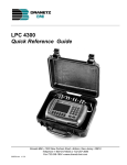
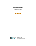
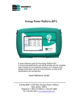
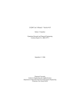
User's Guide
Connecting to a PX5 or 4400 Site to Update Status, continued
2) Move the cursor over the "Connect" button then click the left mouse button. This will
automatically make the connection to the PX5 or 4400 site. The "Connect" button will
change to "Disconnect", which can be used to terminate connection from the Site. If
you wish to download data, do not terminate the connection at this time. There is a
connection progress indicator located at the right end of the tool bar that shows
connection activity is ongoing. The animation stops when connection activity is
terminated.
Result: The following screens will appear. The sample screens below feature a PX5
Site using RS-232 serial port connection. Note that the same procedure applies
and the same functions keys are displayed when connected to a PX5 or 4400
Site using modem connection.
connection
progress
indicator
43
NODELINK Data Management Software
Connecting to a PX5 or 4400 Site to Update Status, continued
3) Once connected to the PX5 or 4400 site, the Site tree directory is automatically
updated. You can now perform the following functions using the appropriate key:
Press Get Data to download event data files from the PX5 or 4400 data card.
NodeLink lists the file names stored in data card along with size of file.
NOTE: NodeLink is equipped with an Autopoll feature if you want to automatically
collect and download event data at specified time intervals. See page 31 for more
information on Autopoll Schedule.
Press Values to display real time meter data.
Press Get Setup to download current setups from the PX5 or 4400 data card.
Press Monitor On/Off to start monitoring or to turn monitoring off.
The message Monitoring Status: On appears on screen while the instrument is
actively recording data.
The following function keys are operable whether the instrument is actively
monitoring data or not: Values, Get Data, Get Setup, and Disconnect. On the other
hand, the following function keys are operable only when monitoring is off: Put Setup,
Set Time, and Format Card. These function keys are discussed in detail in Chapter 6
Instrument Status Page.
Data monitoring continues until the monitoring off key is pressed. The message
Monitoring Status: Off appears to indicate that monitoring has been turned off and
active recording is disabled.
Press Put Setup to load setup template files from the computer hard drive to the PX5
or 4400. Loading new setup parameters is allowed only when monitoring is off.
Press Set Time to manually set the time and date in PX5 or 4400 and synchronize it
with the time and date displayed in the computer running NodeLink. Time
synchronization is allowed only when monitoring is off.
NOTE: Automatic time synchronization when data poll is complete can be enabled
under Autopoll Schedule. See page 31.
Press Format Card to format the data card. Formatting card is allowed only when
monitoring is off. All data and setups stored in the card will be lost when you format
the card. Copy the files that you want to save to a computer first before formatting
card.
For a detailed discussion of these functions, see Chapter 6 Instrument Status page.
44
User's Guide
CHAPTER 6: INSTRUMENT STATUS PAGE
Instrument Status Page
A Site consists of the instruments that are connected to NodeLink. In the case of the
Signature System, the instruments consist of DataNodes that monitor and transmit data
to the InfoNode Site. In the case of the PX5 or 4400, each unit is equipped with the
setup protocols that will allow you to measure and collect data to store under the
NodeLink/PX5 or NodeLink/4400 site. Event data can be viewed using the DranView
program.
Downloading Data from DataNode
The Instrument Status Page provides the following DataNode instrument-specific
information: DataNode site Health status based on continuous checks of the
communication links and internal processes like memory, Description of the instrument
monitoring location and information about the installation for that particular instrument,
instrument software Version, instrument ID, and instrument Serial Number. This
information cannot be changed from the NodeLink program.
1) Once you have connected to an InfoNode Site, expand the Site tree and select/click
on an Instrument from which you want to download data. The Instrument Status Page
will appear on your Main Viewing Area. At this point, the tree directory is locked and
will only allow selection of DataNodes that fall under the InfoNode Site where you are
currently connected. To unlock the tree directory and terminate connection to an
InfoNode site, click the "Disconnect" button that is in the Instrument Status Page.
45
NODELINK Data Management Software
NodeLink will switch back to the Site Status Page once disconnected from the
InfoNode site.
To retrieve data and store it in your computer hard drive under the default
DranetzBMI\NodeLink\Data folder, or whatever data folder you specified prior to
collecting data, click on the "Get Data" button that is in the Instrument Status Page.
2) While the Instrument is downloading data, the Main Viewing Area displays a
message describing the ongoing NodeLink activity. It also displays a "Cancel" button
that can be used to terminate the download procedure. A download progress
indicator appears at the right side of the tool bar showing the number of bytes of
data collected and whether downloading is ongoing or has terminated.
3) Once the data download process is complete, the Instrument Status Page will appear.
You can then use the tree directory to choose another Instrument from which to
download data or you can choose Disconnect to terminate connection from the
InfoNode Site.
46
User's Guide
PX5 or 4400 Data Options
The PX5 or 4400 Instrument Status Page allows users to download event data files,
view real-time meter data from the PX5 or 4400, upload or download setups. It also
allows users to manually turn monitoring on/off at their own designated time. Users can
also set the time and date in PX5 or 4400 and synchronize it with the time and date
displayed in the computer running NodeLink. The Instrument Status Page also features
a function key to format the data card installed in PX5 or 4400.
Once connected to a PX5 or 4400 Site, expand the Site tree to display Download History
(initially empty since no data files have been downloaded yet) and Site Properties page.
The various functions keys that appear on the Main Viewing Area are described below.
To unlock the tree directory and terminate connection to a PX5 or 4400 site, click the
"Disconnect" button that is in the Instrument Status Page. NodeLink will switch back to
the Site Status Page once disconnected from the PX5 or 4400 site.
Get Data: Download Event Data Files from PX5 or 4400 Data Card
To retrieve event data files from the PX5 or 4400 data card and store it in your computer
hard drive under the default DranetzBMI\NodeLink\Data folder, or whatever data folder
you specified prior to collecting data, click on the Get Data button.
Downloading data is allowed whether monitoring is on or off. Users should keep track of
the files they are downloading from the PX5 or 4400 data card especially when
47
NODELINK Data Management Software
monitoring has been turned off and on for a number of times. Note that the filename
used to record files consists of the site name with a number appended to it.
File Naming Conventions
The PX5/4400 allows users to store multiple files in one card using the site name with a
number appended to it as filename. The number automatically increments every time the
user starts monitoring with that same filename.
When NodeLink retrieves the file from the PX5/4400 data card, it stores the file using the
name assigned to it by the PX5/4400 UNLESS the file has already been downloaded
into the same folder. For files already downloaded into the same folder, NodeLink will
append a three digit number to the file name. For each successive download of a file,
NodeLink will increment this appended number.
To illustrate:
When PX5 or 4400 stores files in the data card:
If the site name is Dranetz-BMI_SiteA, the filename will be Dranetz-BMI_SiteA00.ddb.
Where the number 00 increments to 01, then 02, 03, etc. every time PX5/4400
monitoring is turned on and data is saved in the card using the same filename.
For example:
Dranetz-BMI_SiteA00.ddb
Dranetz-BMI_SiteA01.ddb
Dranetz-BMI_SiteA02.ddb
Etc.
When NODELINK gets data files from the PX5/4400 and stores it in the computer:
Using the example above, the first time NodeLink downloads a file, NodeLink will use the
same name used by PX5/4440 and store the file in the computer as DranetzBMI_SiteA00.ddb. HOWEVER, each successive time that NodeLink downloads the
same file, it will append a three digit number to the file.
For example: If you downloaded the file Dranetz-BMI_SiteA00.ddb from the PX5/4400
data card three times, you would have the following three files in your directory:
Dranetz-BMI_SiteA00.ddb
Dranetz-BMI_SiteA00_001.ddb
Dranetz-BMI_SiteA00_002.ddb
Etc.
Downloading Data Using Autopoll
Autopoll uses the same naming convention as NodeLink does the first time it downloads
a file. However, unlike the Get Data function key which allows you to download all files
stored in the PX5/4400 data card, Autopoll downloads ONLY the file that the instrument
is currently monitoring. Another difference is that for the succeeding time that Autopoll
downloads data from the PX5/4400 site, it will append new data to the file already
downloaded. This means that the downloaded file increases in size and no new files are
created.
48
User's Guide
Once the Get Data function key is pressed, the list of PX5 or 4400 event data files
available for download is shown. Check to select the file(s) that you want to download, or
click on Select All if you want to download all files. Once files have been selected, click
on Download to retrieve data files from the PX5 or 4400 memory card and store into the
computer hard drive. You may click on Disconnect to cancel download operation any
time.
The sample screens below show how to download event data files from PX5 or 4400.
Click on Return to exit and go back to the PX5 or 4400 Instrument Status Page.
Get Data
files to
download
Select All files
for download
Download event data files
from PX5 or 4400 data
card; table shows the data
File Name, File Size
(Bytes), and Bytes
Downloaded; checked file
indicates download
complete while number of
bytes indicates download
ongoing; click Disconnect
to cancel download
operation any time
49
NODELINK Data Management Software
Values: Display Real-time Meter Data in NodeLink
To view real-time meter data from the PX5 or 4400, click on the Values button. Basic
power quality parameters like RMS, Frequency and Power values are available for
display. Click on Return to exit and go back to the PX5 or 4400 Instrument Status Page.
50
User's Guide
Get Setup: Download Active Setups from PX5 or 4400 Memory
NodeLink can be used to retrieve the active setups from the PX5 or 4400. This function
allows users to know how the instrument is configured, on the basis of which they can
decide whether or not to make setup changes as they see fit. The Properties page
allows users to make changes on circuit connection, channel probe connection, voltage
and current transducer ratios, and monitoring mode of operation in the PX5 or 4400
measurement device (see page 42). To download current setups from the PX5 or 4400,
click on the Get Setup button.
The screens below show how to download active setups from the PX5 or 4400.
Downloading setups is allowed whether monitoring is on or off. The progress indicator
shows whether download activity is ongoing or not. You may click on Cancel to quit
download setup operation any time. When download setup operation is complete, the
PX5 or 4400 Instrument Status Page is displayed.
51
NODELINK Data Management Software
Monitor On/Off: Turn Data Monitoring On/Off
Users have the option to set data monitoring at specified time intervals under the Autopoll
Schedule (see page 31), or to manually start/stop monitoring using the Monitor On/Off key.
The screens below show how to turn monitoring on/off. The message Monitoring Status: On
appears on screen while instrument is actively recording data. The PX5/4400 automatically
saves data in the card when monitoring is on. Data monitoring continues until monitoring is
turned off. The progress indicator shows whether change in monitoring status is ongoing or
not. The message Monitoring Status: Off appears on screen to indicate that monitoring has
been turned off and active data recording is disabled.
52
User's Guide
Put Setup: Load Setup Changes from NodeLink to PX5 or 4400 Memory
Changes in circuit setup made in the Properties page can become part of the active
setups in PX5 or 4400. NodeLink stores setup files in the computer hard drive as XML
files, and uploads them to become part of the active setup in PX5 or 4400 memory. To
load setups to PX5 or 4400, click on the Put Setup button.
Loading setups is allowed only when monitoring is turned off. If you click on Put Setup
when monitoring is on, a message will appear to indicate that loading new setup
parameters in PX5 or 4400 memory cannot proceed and you need to turn monitoring off.
After new parameters are uploaded and monitoring is turned back on, the PX5 or 4400
will automatically append a number to the filename containing data from the current
monitoring session. The filename is automatically incremented every time the user starts
monitoring with that same filename (see page 48 for file naming convention).
The screens below show how to upload changes in setup from computer hard drive to
PX5 or 4400. The progress indicator shows whether loading activity is ongoing or not.
You may click on Cancel to quit upload setup operation any time. When upload setup
operation is complete, the PX5 or 4400 Instrument Status Page is displayed.
53
NODELINK Data Management Software
Set Time: Synchronize Time Between Computer and PX5 or 4400
Set Time allows users to manually set the clock in the PX5 or 4400 and ensure that the
time and date displayed in the unit is synchronized with the time and date displayed in
the computer once auto-download of event data is complete. Automatic synchronization
of time between computer and instrument can be enabled under the Autopoll Schedule
(see page 31).
Time synchronization is allowed only when monitoring is turned off. If you click on Set
Time when monitoring is on, a message will appear to indicate that setting the clock in
PX5 or 4400 cannot proceed and you need to turn monitoring off.
After time has been set and monitoring is turned back on, a number is automatically
appended to the filename containing data from the current monitoring session. The
filename is automatically incremented every time the user starts monitoring with that
same filename (see page 48 for file naming convention).
54
User's Guide
Format Card: Format Data Card
NodeLink allows users to format the data card installed in PX5 or 4400 in preparation for
monitoring or writing of data. Data monitoring cannot proceed without a properly
formatted card installed in the PX5 or 4400 card slot. Formatting card is allowed only
when monitoring is turned off. If you click on Format Card when monitoring is on, a
message will appear to indicate that card formatting cannot proceed and you need to
turn monitoring off.
NOTE: All data and setups stored in the card will be lost when you format the card. Copy
the files that you want to save to a computer first before formatting card.
55
NODELINK Data Management Software
This page intentionally left blank.
56
User's Guide
CHAPTER 7: DOWNLOAD HISTORY PAGE
Download History Page
Once you have downloaded data, expand the Instrument tree (in the case of the
InfoNode) or the Site tree (in the case of the PX5 or 4400) to display the Download
History page. Click on Download History to display a chronological list of all data files
downloaded for a particular Instrument/Site. If the list is empty, then there are no
downloaded files stored in your hard drive.
Viewing Event Data from InfoNode Site
Event data files downloaded from a DataNode are listed under the Download History
page. Each data file shows the following information: Date of File Transfer, Date of Last
Event, and Date of First Event. Users can re-arrange the columns by selecting a column
header with the cursor and left mouse button then dragging it into a new position.
Double clicking on the row of a selected data file will automatically launch the default
viewer/analysis program.
There are two requirements before you can view downloaded data files from the
InfoNode site. First requirement is to have the necessary viewer/analysis software
application installed in your computer. The DranView or PQView application can be
used to view event data files stored in InfoNode sites. These viewer/analysis programs
are purchased separately from NodeLink. Second requirement is that you can only view
data when you are not actively connected to any InfoNode Site. To terminate connection
from an InfoNode Site, click on the "Disconnect" button that is in the Instrument Status
Page.
57
NODELINK Data Management Software
1) Expand the Instrument tree (DataNode) by clicking on the plus sign to show
Download History. Click on Download History to show the Download History Page
which contains the list of downloaded data files (see screen on page 57).
2) Double-click on the file row bearing the date range that you wish to display in the
viewer. This automatically launches the default viewer/analysis program to display
the selected data file.
Result: The following screens will appear.
Viewer/Analysis
program
automatically
appears to show
plots of selected
data file
58
User's Guide
Viewing Event Data from PX5 or 4400 Site
Event data files downloaded from a PX5 or 4400 are listed under the Download History
page. Each data file shows the following information: Date of File Transfer and Name of
File. Users can re-arrange the columns by selecting a column header with the cursor
and left mouse button then dragging it into a new position. Double clicking on the row of
a selected data file will automatically launch the default viewer/analysis program.
There are two requirements before you are able to view downloaded data files from the
PX5 or 4400 site. First requirement is that you have the viewer/analysis software with
drivers specific for the PX5 or 4400 installed in your computer. The DranView
application with PX5 or 4400 driver is used to view event data files stored in PX5 or 4400
sites. The viewer/analysis program is purchased separately from NodeLink. Second
requirement is that you can only view data when you are not actively connected to any
PX5 or 4400 Site. To terminate connection from a PX5 or 4400 Site, click on the
"Disconnect" button that is in the Instrument Status Page.
1) Expand the Instrument tree by clicking on the plus sign to show Download History.
Click on Download History to show the Download History Page which contains the list
of downloaded data files.
2) Double-click on the file row bearing the date range that you wish to display in the
Viewer. This automatically launches the DranView viewer/analysis program to display
the selected data file.
Result: See page 60 for the resulting screens.
59
NODELINK Data Management Software
Viewer/Analysis
program
automatically
appears to show
plots of selected
data file
60
User's Guide
APPENDIX A
PX5/4400 – NodeLink Communications Setup
NodeLink allows users to download and archive event-type data from the PX5 and 4400
via Direct-RS232 connection or via modem connection.
Direct-RS232 Connection Setup
To download events from PX5/4400 through the optical port, you must have the
following: a personal computer or laptop with Windows® operating system with either
RS232 serial port or network adapter, NodeLink®, and the appropriate Isolated
Communication Module assembly as described below.
The Isolated Communication Module assembly consists of two parts:
1. A fiber optic cable (P/N 900406) which connects the PX5/4400 optical serial port to
the communication module;
2. The communication module which is available in three types:
a 9-pin RS232 Communication Module (P/N COMM-RS232)
a USB Communication Module (P/N COMM-OUA)
an Ethernet Communication Module (P/N COMM-OEA)
The communication modules are optically isolated devices using infrared light to transfer
text and graphics to a computer running NodeLink. These modules are designed to
connect the PX5/4400 optical serial port to the appropriate interface - either a standard
RS232 serial port connector, USB adapter, or Ethernet adapter.
Each adapter interface is supported using the computer’s standard serial ports.
61
NODELINK Data Management Software
Connection Setup via RS232
The following procedure and diagram describe how to connect the PX5/4400 to a
computer via RS232.
1. Connect one end of the fiber optic cable (P/N 900406) into the Fiber Optic Serial Data
Port located on the left side panel of the PX5/4400.
2. Connect the other end of the fiber optic cable into the Fiber Optic Port on the plastic
housing of the 9-pin/RS232 Communication Module (P/N COMM-RS232).
3. Connect the 9-pin RS232 connector to any available serial COM port on your
computer.
NOTE: If the RS232 COM port on your computer supplies voltage power, the battery
charger/UPS for DC power input is not required. Otherwise, COMM-RS232 requires that
an external power source be connected. For external power supply, use the optional
accessory Battery Charger/UPS (P/N XBC-PX5) available from Dranetz-BMI. Connect
the DC plug from the battery charger/UPS to the 12V, 3W max input jack on the RS232
adapter. Configure the AC power plug of the battery charger by sliding the proper plug
supplied (US, Euro, UK or Australia) and locking it into place. Connect the AC power
plug of the battery charger to the proper power source 120V AC for US type plug or
230V AC for Euro, UK or Australia type plug.
TO PX5 OR 4400
OPTICAL PORT
62
User's Guide
Connection Setup via USB
The following procedure and diagram describe how to connect the PX5/4400 to a
computer via USB.
1. Connect one end of the fiber optic cable (P/N 900406) into the Fiber Optic Serial Data
Port located on the left side panel of the PX5/4400.
2. Connect the other end of the fiber optic cable into the Fiber Optic Port on the plastic
housing of the 9-pin/RS232 Communication Module (P/N COMM-RS232).
3. Connect the 9-pin RS232 connector to the USB to RS232 Serial Adapter.
4. Install the software on the compact disc that came with your USB to RS232 Serial
Adapter. This will create a virtual COM port on your computer at the next available serial
port.
5. Connect the USB cable from a USB port on your computer to the USB socket of the
RS232 Serial Adapter.
6. Check the Device Manager in the Windows® control panel to identify the new COM
port number created by the USB - RS232 Serial device. Use this COM number to
connect the PX5/4400 with NodeLink.
Fiber Optic to RS232
ADAPTER
TO PC USB PORT
USB to RS232
ADAPTER
DB9
63
TO PX5 OR 4400
OPTICAL PORT
NODELINK Data Management Software
Connection Setup via Ethernet
The following procedure and diagram describe how to connect the PX5/4400 to a
computer via Ethernet.
1. Connect one end of the fiber optic cable (P/N 900406) into the Fiber Optic Serial Data
Port located on the left side panel of the PX5/4400.
2. Connect the other end of the fiber optic cable into the Fiber Optic Port on the metal
housing of the Ethernet Communication Module (P/N COMM-OEA).
3. The COMM-OEA requires connection to an external power source. Connect the DC
plug from the AC adapter supplied (P/N 11707-G1) to the 12V, 3W max input jack on the
Ethernet adapter. Configure the AC power plug of the battery charger by sliding the
proper plug supplied (US, EURO, UK or Australia) and locking it into place. Plug the AC
power plug of the battery charger to the proper source 120V AC for US type plug or
230V AC for Euro, UK or Australia type plug.
NOTE: For battery backup operation, replace the AC adapter with the optional accessory
Battery Charger/UPS (P/N XBC-PX5) available from Dranetz-BMI.
4. Set the IP configuration of the Ethernet Communication Module. Consult your IT
Department for the appropriate setting of your local area network. Refer to the PX5 or
4400 User’s Guide, Chapter 4 Instrument Settings - Communications, for the procedure
on how to enter IP settings in PX5/4400.
5. Connect the Ethernet port on the Ethernet Communication Module to the local area
network to which your computer is connected to.
6. Install the software contained in the compact disc that came with your Ethernet
Communication Module. This will install the “Real COM Installer Program” plus some
utility programs from MOXA Technology, Inc.® for the Ethernet Communication Module
on your computer.
7. Run the Real COM Installer. Map and activate a COM port to the first available COM
port on your computer.
TO PX5 OR 4400
OPTICAL PORT
DC POWER INPUT
64
User's Guide
Recommended Modem Connection Setup
When configuring both the PX5/4400 and NodeLink for modem communications, keep in
mind that the PX5/4400 uses a fiber optic serial port in order to maintain electrical
isolation. This means that there are no control signals available to a modem to use for
handshaking and flow control.
It is highly recommended that identical modems be used on the PX5/4400 and the
computer. Identical modems will have the same internal buffering and are more likely to
negotiate modulation, speed, and error correction suitable to both modems. If the
modems used are not identical then both the PX5/4400 and the computer should have
modems with the same chipset (i.e. Rockwell, Lucent).
When configuring for modem communications, the first decision to be made is the port
speed for both ends of the communications link. This is the speed at which the
PX5/4400 communicates with its modem and the speed at which the computer
communicates with its modem. The same speed should be chosen for both. Ideally the
speed should be at or just below the anticipated modem connect speed. Since most
modems today will attempt to connect at least at 56 kbps, 38.4 kbps would be a good
choice for the two port speeds. This helps to prevent possible modem buffer overflow.
Follow the steps below to configure the PX5/4400 for a port speed of 38.4 kbps. Refer to
the PX5 or 4400 User’s Guide, Chapter 4 Instrument Settings – Communications, for the
PX5/4400 screen interface.
1. Connect the modem to the PX5/4400 communications adapter.
2. Turn on the modem.
3. From the PX5/4400 home screen, click on the Preferences icon.
4. Choose Communications from the Instrument Settings Setup Menu.
5. Verify that both the Enable Communications and External Modem Connected
checkboxes are enabled (checkboxes checked).
6. Check to enable 38400 under Baud Rate (bps).
NOTE: The port speed of 38400 (38.4 kbps) used above may be substituted with 57600.
Experiment to find the maximum port speeds that will work for the system.
7. Note the modem initialization string at the bottom of the screen. Do not exit this
screen yet since you may be modifying this string after you have the Windows® modem
configured.
65
NODELINK Data Management Software
NodeLink uses Windows® TAPI when accessing modem communications resources. The
assumption is that the Windows® modem to be used for PX5/4400 communications has
been properly installed prior to executing this procedure.
If the modem is not on, or was not on when Windows® was started, it may be necessary
to turn the modem on and restart Windows®. Windows® searches for installed serial
modems at startup. If it does not find them, it may not allow them to be configured in the
Control Panel.
Follow the steps below to configure the port speed for the Windows® modem in your
computer:
1. Press the Start button.
2. Select Settings and then Control Panel.
3. Double-click on Phone and Modem Options.
4. Select Modems in the subsequent dialog box.
5. In the list of modems that is displayed, click to highlight the modem in question and
select Properties.
6. On the General tab of the modem properties dialog box, select 38400 as the
maximum port speed.
7. Click OK to exit from the open dialog boxes.
8. Close the Control Panel.
It is important to note that the port speed of 38400 (38.4 kbps) may be substituted with
57600. Experiment to find the maximum port speeds that will work for the system.
Back at the PX5/4400, the last step in configuring the modem communications is to
modify the modem initialization string to match the modems and chipsets being used.
The goal is to configure for the following:
Restore factory settings.
Set auto-answer to answer on one or two rings (more than two rings are allowed but
at some point the number of rings may start to conflict with NodeLink timeouts).
Turn hardware flow control off since you are using a "two-wire" connection (fiber optic
port).
Set a modem inactivity timeout of 60 seconds. The modem will hang up after one
minute of continuous inactivity on the line.
Select the minimum allowable baud rate.
66
User's Guide
Follow the steps below to change the modem initialization string. Refer to the PX5 or
4400 User’s Guide, Chapter 4 Instrument Settings – Communications, for the PX5/4400
screen interface.
1. From the PX5/4400 Communications Settings screen used to configure modem
connection speed, click on the Change button to the right of the string field display.
2. Use the virtual keypad that appears on the screen to change and enter the new string
command. The modem initialization string commands for the Conexant (Rockwell)
chipset and the Agere (Lucent) chipset are discussed in the next section.
3. When done, click on OK to accept changes in modem communications settings.
Modem Initialization String Command
The following is the AT initialization string for a modem using the newer Conexant
(Rockwell) chipset:
AT&F;S0=2;+IFC=0,0;S30=6
Where:
AT is the modem attention command
&F instructs the modem to restore factory configuration
S0=2 turns auto-answer on and sets the number of rings to answer to two.
+IFC=0,0 turns flow control off.
S30=6 sets a 60 second inactivity modem hang up timeout.
; is a command delimiter.
NOTE: It may be necessary to adjust the modem connection speeds to specify a
minimum baud rate. This is possible using the +MS modem command. Check the
modem manual for use of the +MS command. There are several varieties of the
command. Typically, a modem modulation scheme and minimum and maximum transmit
and receive speeds can be specified. Using Hyperterminal, it is possible to get a list of
the possible command ranges and syntax by typing AT+MS=?.
The following is the AT initialization string for a modem using the Agere (Lucent) chipset:
AT&F;S0=2;&K0;%E0;S30=6
Where:
AT is the modem attention command.
&F instructs the modem to restore factory configuration.
S0=2 turns auto-answer on and sets the number of rings to answer to two.
&K0 turns flow control off.
%E0 disables baud rate fall back/fall forward.
S30=6 sets a 60 second inactivity modem hang up timeout.
; is a command delimiter.
A similar note regarding connect speeds applies. Try using the AT-V90= command and
modifying the contents of S registers S37 and S38.
67