1
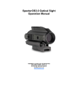
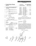
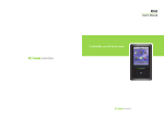
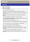
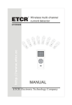
SpecterOS4x Optical Sight Operation Manual ARMAMENT TECHNOLOGY INCORPORATED 3045 ROBIE STREET, SUITE 113 HALIFAX NS B3K 4P6 CANADA [email protected] www.armament.com TABLE OF CONTENTS CHAPTER 1 CHAPTER 2 CHAPTER CHAPTER DESCRIPTION, DATA AND OPERATION……………… Page 2 1.1 Description ………………………………………………….. Page 2 1.2 Technical Data ……………………………………………… Page 3 1.3 Location of Controls………………………………………… Page 4 2.1 2.2 2.3 2.4 2.5 QUICK START……………………………………………… Page 6 Mounting……………………………………………………… Page 6 SpecterOS4x Operation……………………………………. Page 6 Quick Zeroing ……………………………………………….. Page 7 Reticle Illumination………………………………………….. Page 8 Changing the Battery……………………………………….. Page 9 3.1 3.2 3.3 3.4 3.5 3.6 OPERATION………………………………………………… Page 10 General………………………………………………………. Page 10 Installation…………………………………………………… Page 10 Method of Adjustment………………………………………. Page 10 Dry Zeroing or Initial Alignment…………………………… Page 10 Zeroing………………………………………………………. Page 11 Reticle & Ranging………………………………………….. Page 13 3 4 MAINTENANCE…………………………………………….. Page 15 SpecterOS4x Operation Manual Page 1 GENERAL DESCRIPTION & SPECIFICATIONS 1.1 Description The SpecterOS4x Optical Sight (Figure 1-1) is a fixed power 4x optical telescopic weapon sight which mounts on a MIL-STD-1913 ‘Picatinny’ rail. The optical sight consists of single main housing that encloses the optics, and the integral mount assembly. This design places all of the optics in a sealed, hardened optical housing protected from the environment. All mechanical adjustments of the sight are controlled by the elevation and azimuth zeroing mechanisms in the mount assembly. The optical housing has a 32mm objective lens and an 8mm diameter exit pupil, which provides excellent vision in low light levels. It also provides for rapid target acquisition and identification at short, intermediate, and long ranges. The sight incorporates LED’s for red dot and reticle illumination under CQB or low light conditions. The ballistically compensated reticle consists of a cross hair or chevron with horizontal stadia lines for shooting at various ranges. The SFOV4-C1 model incorporates a Vertical Subtention Optical Rangefinder (VSOR) within the field of view. The optical sight has no internal surfaces that will reflect laser interrogation. The exterior includes heavy rain / emergency aiming features on top of the optical housing and incorporates a hard-anodized external finish. Figure 1-1 Selected Overall Views The mount has two levers which fasten the sight to the ‘Picatinny’ rail and allow the sight to be removed and reattached without the need to re-zero. The mount is adjustable for zero in both elevation and azimuth (windage). The mount is designed to withstand rough usage in operation. Anti-backlash springs in the elevation and azimuth mechanisms permit flexibility, but always return the sight to the zero position. A tension spring between the optical main body and the mount rail grabber removes vertical movement by applying tension to the two halves of the mount. SpecterOS4x Operation Manual Page 2 Figure 1-2 Long eye relief facilitates use with most back up iron sights. 1.2 Technical Specifications (Nominal) Specification Yes, with adapter plate Fixed Magnification(s) 4.0 X Auxiliary Sight Field of View 6½° Aiming Point Crosshair or Chevron Reticle Pattern Ballistic compensated crosshair Entrance Optic Diameter 32 mm Exit Pupil 8.0 mm Illumination Eye Relief 70mm Operating Temp -40 to +65 °C Optical Axis Height 39mm Storage Temp -40 to +85 °C Zeroing Range Zeroing Click Size Mount Compatibility ±60 MOA Salt Fog >40 hrs. @ 5% MIL-STD 1913 Chemical NBC & Cleaning A.R.M.S. Levers Weight With Mount SpecterOS4x Operation Manual >2 hours @ 66 ft ½ MOA Mount Attachment Length, Width, Height Submersion LED Battery / Life DL 1/3 N (3000hrs Avg) 515g Finish Hard Anodized (Class III) 153mm x 67mm x 65mm Color Black Page 3 1.3 SpecterOS4x Controls and Terminology Figure 1-3 1.3.1 Left Side View and Selected Controls Auxiliary Sight Mounting Capability The SpecterOS4x does not incorporate Integral back-up iron sights. Should the user desire, an auxiliary sight (mini Red Dot Sight) may be installed on top of the SpecterOS4x in conjunction with the optional MRD Mounting Kit. 1.3.2 Battery Cap The fluted battery cap sits on top of the Illumination Rotary Switch. It can be removed by hand by unscrewing it counter clockwise (CCW). The battery cap should only be tightened by hand until snug so that it can later be removed by hand. 1.3.3 Mount Locking Levers The locking levers are used to secure the sight to the weapon’s “Picatinny” rail. SpecterOS4x uses 2 ARMS type low profile locking levers that point rearward when locked. The mount base also provides for additional tie/wire wrap points so that the ARMS levers can be locked in place if desired. 1.3.4 Elevation Zeroing Dial The zero dial is located at the lower rear of the mount. This dial allows for elevation zeroing only while the elevation zeroing lock is disengaged. 1.3.5 Elevation Zeroing Lock The elevation zeroing lock (silver tab) is located just above the elevation zeroing dial. It is only used during elevation zeroing. Move the lock UP to permit ½ MOA per click elevation zeroing. Move the lock DOWN to lock the elevation zero. Important: To prevent damage be sure that the lock is fully disengaged before attempting to turn the elevation zeroing dial. SpecterOS4x Operation Manual Page 4 1.3.6 Azimuth Reference The front yoke on the sight housing has space gaps between the yoke and the mount base plate. When each of the two gaps shows equal spacing, the sight is roughly at azimuth centre. Figure 2-4 1.3.7 Azimuth (Windage) Adjustment Screw The azimuth adjustment screw is located at the front left side of the mount. It is rotated to left or right to change the Mean Point of Impact (MPI) of the bullets. A coin or rim of a bullet can be used to turn the adjustment screw. Rotate the screw clockwise to move the point of impact to the left. Rotate the screw counter clockwise to move the point of impact to the right. Each ‘click’ moves the point of impact ½ Minute of Angle (MOA) (approximately ½” at 100 yards). 1.3.8 Reticle Illumination Knob Rotation of the knob illuminates the reticle at varying levels of brightness. Reference marks on the housing indicate the operating positions of the switch 1. Counter Clockwise from off, illuminates the central aiming mark (cross or chevron) with 5 intensity levels: 2 for Night Vision equipment use, and 3 for low light and daytime use. 2. Clockwise from off, illuminates the ballistic reticle with 5 intensity levels: 2 for Night Vision equipment use, and 3 for low light use. NOTE: The SpecterOS4x is designed for use with forward mounted night vision devices such as the AN/PVS-22 . Reticle illumination settings may be too bright for use with rear-mounted night vision devices such as AN/PVS-14. SpecterOS4x Operation Manual Page 5 CHAPTER 2 2.1 QUICK START Mounting Ensure the weapon is unloaded. Loosen the mount lever locks and place the sight onto the rail. Adjust the eye relief as per instructions in section 2.2 Once correct eye relief is set, tighten the mount levers to lock the sight to the rail. Slots permit installation of wire ties. Figure 2-1 Levers lock sight to MIL-STD 1913 rail. 2.2 ADJUSTING EYE RELIEF When viewing through the sight, proper eye relief causes the scene field of view to be a circular and sharp image, see Figure 2-2. It may be necessary to move the optical sight either backwards or forward on the weapon in order to achieve the correct eye relief for the users natural shooting position. (a) CORRECT INCORRECT (b) (c) Figure 2-2 (a) Eye shown at proper 2.75 inch eye relief distance from rearmost glass surface. (b) Image through sight is sharp and circular when eye is placed at or near the proper eye relief distance. (c) Image through sight when eye is too close to or too far from optimal viewing distance. SpecterOS4x Operation Manual Page 6 Figure 2-3 2.3 QUICK ZEROING Detailed zeroing is provided later in this manual. The following procedure is provided for users familiar with optical sight zeroing. ● Azimuth zeroing uses the windage screw found at the front of the mount. Rotate the front left windage screw clockwise to move the point of impact to the left; counter clockwise to move to the right. Each click of the windage screw moves the point of impact by one-half MOA (approximately 1/2” at 100 yards). Figure 2-4 ● Elevation zeroing uses the elevation dial the bottom rear of the mount. Unlock the zeroing lock (silver tab) by raising it up as far as it will go. Be sure that the lock pin at the bottom of the zeroing lock is fully disengaged from the elevation dial. ● Adjust the elevation dial as required. Each click of the elevation dial moves the point of impact by one-half MOA (approximately 1/2” at 100 yards). Turn the dial to the Right to Raise the point of impact, turn to the Left to Lower the point of impact. When satisfied with elevation zero, lower the zeroing lock (silver tab) fully to lock the elevation zero at its current setting. SpecterOS4x Operation Manual Page 7 Figure 2-4. Azimuth & Elevation Zeroing Adjusts 2.4 RETICLE ILLUMINATION The SpecterOS4x provides two reticle modes, see Figure 2-5: A central aiming feature at the centre of the crosshairs (cross or chevron) A Range Estimating and Drop Compensation Reticle Each reticle mode has multiple brightness settings and are set by the Illumination switch (rotary) on the left side of the sight, Figure 2-6. Figure 2-5 Illuminated Ballistic Reticle and central aiming cross. (model SFOV4-C1) SpecterOS4x Operation Manual Figure 2-6 Rotate the Illumination switch to desired reticle brightness setting. Page 8 RETICLE ILLUMINATION continued. Figure 2-7 Illuminated Ballistic Reticle with central aiming chevron (model SFOV4-A1). 2.5 Figure 2-8 Rotate the Illumination switch to desired reticle brightness setting. CHANGING THE BATTERY To change the battery, remove the battery cover by gripping the smaller diameter fluted section of the Illumination Switch and rotating counter clockwise until the cover is removed. Place a new 1/3 AA Lithium battery into the compartment with the “+” terminal facing out. Figure 2-9 Battery replacement SpecterOS4x Operation Manual Page 9 CHAPTER 3 DETAILED OPERATION 3.1 General The following procedures are used to operate the SpecterOS4x Optical Sight. 3.2 Installation Before installing the sight, be sure the weapon is unloaded. To install the optical sight proceed as follows: Assume the normal firing position. Loosen the mount levers until they are perpendicular to the body of the sight. Place the sight on top of the rail (but not into a rail notch) and slide the sight along the rail to find the position where a full field of view is visible through the sight (approximately 2.75 inches of eye relief) by a minimizing of the tunnel effect of the field of view. Note the position of the sight on the rail. NOTE: A common mounting position on a M4 Carbine or M16 Rifle receiver is with 3 slots visible in front of the sight. Mount the optical sight on the rail at the closest match of mount slot bar and rail slots. Push the sight to the forward most position within the slot. Tighten the mount levers in towards the sight body until they are parallel to the sight body. For extra mounting security, the mount provides slots to accommodate plastic or wire tie wraps so that the levers can be locked into their closed position. The sight is now mounted on the weapon. 3.3 Method of Adjustment The optical sight now has to be zeroed to align the point of aim with the point of impact of the bullet. Azimuth zeroing adjustments are performed by placing a coin into the windage screw and rotating the screw clockwise or counter clockwise. The Elevation Adjust at the back of the mount, under the eyepiece. A lock (silver tab) must be disengaged (lifted up) to adjust the elevation zero. This lock should always be engaged (pushed down) when not zeroing. It is very important that the lock be fully disengaged (all the way up) before the elevation adjustment dial is turned. 3.4 Dry Zeroing or Initial Alignment Initial adjustment of the optical axis is required so that it is in rough alignment with the bore axis of the weapon. This will make zeroing easier to accomplish. There are two simple ways to accomplish a rough zero that will provide a good starting place for live fire zeroing. 3.4.1 Dry zero the optical sight as follows: 3.4.1.1 WINDAGE: Adjust the azimuth adjust until the gaps between the mount base and the optical housing forks are equal. SpecterOS4x Operation Manual Page 10 3.4.1.2 ELEVATION: Disengage the elevation zero lock by pushing it up. Ensure that the lock is fully disengaged from the elevation dial. 3.4.1.3 3.4.1.4 3.5 Rotate the range dial clockwise or counter clockwise until the main housing and clamping plate are approximately parallel. Re-engage the zero lock by moving it back down fully. Zeroing Zeroing should be performed at 100 meters. It is recommended that the marksman fires three-round groups and make adjustments based upon the estimated geometric centre of those groups. 3.5.1 (Figure 3-1, 3-2) The process for zeroing is depicted in the following illustrations and descriptions. 3.5.2 To move the MPI (Mean Point of Impact) to the left, rotate the windage shaft clockwise. To move the MPI (Mean Point of Impact) to the right, rotate the windage shaft counter clockwise. Figure 3-1. Azimuth (Windage) Zeroing Adjustment SpecterOS4x Operation Manual Page 11 Figure 3-2. Elevation Zeroing Adjustment 3.5.3 To Zero Elevation; Disengage the elevation zero lock by lifting it up. Be sure that the lock pin is fully disengaged from the elevation zeroing dial. The elevation adjust will now rotate. With the lock disengaged, rotate the elevation zeroing dial to the left to move the MPI down; or to the right to move the MPI up. RANGE IN METRES 25 50 100 200 300 400 500 600 700 800 MPI MOVEMENT IN mm PER CLICK OF ADJUSTMENT AZIMUTH or ELEVATION ( ½ MOA ) 4 7 15 29 44 58 73 87 102 116 MPI MOVEMENT IN INCHES PER CLICK OF ADJUSTMENT AZIMUTH or ELEVATION ( ½ MOA ) 0.1 0.3 0.6 1.1 1.7 2.3 2.9 3.4 4.0 4.6 Table 3-3 MPI Movements for each Click of Sight Adjustment SpecterOS4x Operation Manual Page 12 3.6 RETICLE AND RANGING 3 300 400 500 5 6 7 4 5 6 7 8 8 600 30 in / 76 cm Figure 3-4. SFOV4-C1 Reticle - Calibrated for 5.56 NATO 62 GR FMJ Figure 3-5. SFOV4-A1 Reticle - Calibrated for 5.56 NATO 62 GR FMJ The reticle of the Optical Sight provides the shooter with easily located aiming marks to designate the target at both short and long ranges. 3.6.1 The main horizontal line is intended to provide a reference to the marksman. This main horizontal line also coincides with the 100 meter aiming point. This reticle pattern is designed to be zeroed at 100 meters. 3.6.2 A central aiming feature (either a fine cross or a chevron) is placed at the reticle centre. This aiming point is designed for use during for direct fire at 200 meters or closer. 3.6.3 The ballistic reticle also provides aiming marks for various extended ranges. Most ranges are labelled beside the aiming mark. To assist in sight picture clarity, a 200m aiming mark has been omitted. At each range, the width of the horizontal aiming mark represents 19” on the target. SpecterOS4x Operation Manual Page 13 300 400 500 600 ____________________________________________________________________________________ ↑ ↑ 30” or 76cm @500m ↓ 30” or 76 cm @300m __________________ __________________ __________________ ↓ __________________ Figure 3.6 VSOR Rangefinder 3.6.4 Use of the VSOR Rangefinder (Model SFOV4-C1 only) The Vertical Subtention Optical Rangefinder (VSOR) allows the marksman to estimate the distance to targets by matching the height of a known object within the field of view. The vertical distance for range estimation is 76 centimeters or 30 inches. By selecting the set of rangefinder lines that best fit a 30 inch or 76 cm object, the marksman may read the correct range at the top of the rangefinder. Once the range is known, the marksman may engage targets at that range by aiming from the appropriate ballistic aiming mark in the reticle. SpecterOS4x Operation Manual Page 14 CHAPTER 4 MAINTENANCE 4.1 Care and Cleaning To clean the lenses, use lens paper or clean optical quality cleaning cloth. Wipe in a circular motion using light pressure. Should these materials not be available, a clean cotton cloth moistened with alcohol will suffice. CAUTION DO NOT use fingers to clean lenses. Apply only a light downward pressure on the cleaning material. DO NOT immerse the SpecterDR sight in solvents. DO NOT use hot water to clean the sight. If mud or hardened dirt are on or near the lens. Flush with cold or warm water and gently wipe with a moistened tissue. Repeat the procedure above if necessary. ARMAMENT TECHNOLOGY INCORPORATED 3045 ROBIE STREET, SUITE 113 HALIFAX NS B3K 4P6 CANADA [email protected] www.armament.com Proprietary Notice This document contains information that is proprietary to Armament Technology Incorporated. This information remains the property of the Company and shall not be reproduced, used or disclosed in any manner or for any purpose not authorized in writing by the Company. SpecterOS4x Operation Manual Page 15