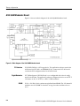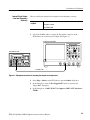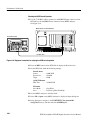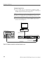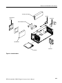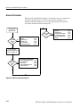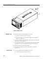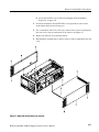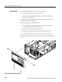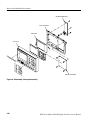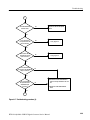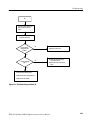
1
Service Manual RTX130A QAM & VSB RF Signal Generator 071-1863-00 Test Equipment Depot - 800.517.8431 - 99 Washington Street Melrose, MA 02176 - FAX 781.665.0780 - TestEquipmentDepot.com Table of Contents General Safety Summary . . . . . . . . . . . . . . . . . . . . . . . . . . . . . . . . . . . Service Safety Summary . . . . . . . . . . . . . . . . . . . . . . . . . . . . . . . . . . . . Environmental Considerations . . . . . . . . . . . . . . . . . . . . . . . . . . . . . . . Preface . . . . . . . . . . . . . . . . . . . . . . . . . . . . . . . . . . . . . . . . . . . . . . . . . . . vii ix xi xiii Introduction . . . . . . . . . . . . . . . . . . . . . . . . . . . . . . . . . . . . . . . . . . . . . . xv Manual Structure . . . . . . . . . . . . . . . . . . . . . . . . . . . . . . . . . . . . . . . . . . . . . . . . Manual Conventions . . . . . . . . . . . . . . . . . . . . . . . . . . . . . . . . . . . . . . . . . . . . . . xiii xiv Performance Check Interval . . . . . . . . . . . . . . . . . . . . . . . . . . . . . . . . . . . . . . . . Strategy for Servicing . . . . . . . . . . . . . . . . . . . . . . . . . . . . . . . . . . . . . . . . . . . . . Tektronix Service Offerings . . . . . . . . . . . . . . . . . . . . . . . . . . . . . . . . . . . . . . . . xv xv xvi Product Overview . . . . . . . . . . . . . . . . . . . . . . . . . . . . . . . . . . . . . . . . . Specifications . . . . . . . . . . . . . . . . . . . . . . . . . . . . . . . . . . . . . . . . . . . . . 1-1 1-3 Specifications Performance Conditions . . . . . . . . . . . . . . . . . . . . . . . . . . . . . . . . . . . . . . . . . . . Functional Specifications . . . . . . . . . . . . . . . . . . . . . . . . . . . . . . . . . . . . . . . . . . Electrical Specifications . . . . . . . . . . . . . . . . . . . . . . . . . . . . . . . . . . . . . . . . . . . Mechanical (Physical) Characteristics . . . . . . . . . . . . . . . . . . . . . . . . . . . . . . . . Environmental Characteristics . . . . . . . . . . . . . . . . . . . . . . . . . . . . . . . . . . . . . . Certifications and Compliances . . . . . . . . . . . . . . . . . . . . . . . . . . . . . . . . . . . . . 1-3 1-3 1-4 1-12 1-12 1-13 A12 Main Board . . . . . . . . . . . . . . . . . . . . . . . . . . . . . . . . . . . . . . . . . . . . . . . . . A20 PCI Backplane Board . . . . . . . . . . . . . . . . . . . . . . . . . . . . . . . . . . . . . . . . . A180 QAM Modulator Board . . . . . . . . . . . . . . . . . . . . . . . . . . . . . . . . . . . . . . A30 Front Panel Board . . . . . . . . . . . . . . . . . . . . . . . . . . . . . . . . . . . . . . . . . . . . A35 Power Switch Board . . . . . . . . . . . . . . . . . . . . . . . . . . . . . . . . . . . . . . . . . . A40 AC Distributer Board . . . . . . . . . . . . . . . . . . . . . . . . . . . . . . . . . . . . . . . . . A50 Disk I/F Board . . . . . . . . . . . . . . . . . . . . . . . . . . . . . . . . . . . . . . . . . . . . . . 2-1 2-3 2-4 2-6 2-6 2-7 2-7 Theory of Operation Performance Verification Equipment Required . . . . . . . . . . . . . . . . . . . . . . . . . . . . . . . . . . . . . . . . . . . . . . RTX130A Test Record . . . . . . . . . . . . . . . . . . . . . . . . . . . . . . . . . . . . . . . . . . . . Procedures . . . . . . . . . . . . . . . . . . . . . . . . . . . . . . . . . . . . . . . . . . . . . . . . . . . . . . RTX130A QAM & VSB RF Signal Generator Service Manual 3-1 3-3 3-4 i Table of Contents Maintenance Related Maintenance Procedures . . . . . . . . . . . . . . . . . . . . . . . . . . . . . . . . . . . . Preparation . . . . . . . . . . . . . . . . . . . . . . . . . . . . . . . . . . . . . . . . . . . . . . . . . . . . . Inspection and Cleaning . . . . . . . . . . . . . . . . . . . . . . . . . . . . . . . . . . . . . . . . . . . 4-1 4-2 4-3 Removal and Installation Procedures . . . . . . . . . . . . . . . . . . . . . . . . . 4-7 Preparation . . . . . . . . . . . . . . . . . . . . . . . . . . . . . . . . . . . . . . . . . . . . . . . . . . . . . Access Procedure . . . . . . . . . . . . . . . . . . . . . . . . . . . . . . . . . . . . . . . . . . . . . . . . Procedures for External Modules . . . . . . . . . . . . . . . . . . . . . . . . . . . . . . . . . . . Procedures for Board Modules . . . . . . . . . . . . . . . . . . . . . . . . . . . . . . . . . . . . . . Procedures for Internal Modules . . . . . . . . . . . . . . . . . . . . . . . . . . . . . . . . . . . . 4-7 4-14 4-15 4-21 4-26 Setting the BIOS Configuration . . . . . . . . . . . . . . . . . . . . . . . . . . . . . 4-35 Troubleshooting . . . . . . . . . . . . . . . . . . . . . . . . . . . . . . . . . . . . . . . . . . . 4-37 Using the Recovery Discs . . . . . . . . . . . . . . . . . . . . . . . . . . . . . . . . . . . 4-47 Options . . . . . . . . . . . . . . . . . . . . . . . . . . . . . . . . . . . . . . . . . . . . . . . . . . 5-1 Diagrams . . . . . . . . . . . . . . . . . . . . . . . . . . . . . . . . . . . . . . . . . . . . . . . . . 6-1 Parts Ordering Information . . . . . . . . . . . . . . . . . . . . . . . . . . . . . . . . . . . . . . . . . Using the Replaceable Parts List . . . . . . . . . . . . . . . . . . . . . . . . . . . . . . . . . . . . 7-1 7-2 Procedure . . . . . . . . . . . . . . . . . . . . . . . . . . . . . . . . . . . . . . . . . . . . . . . . . . . . . . Troubleshooting Trees . . . . . . . . . . . . . . . . . . . . . . . . . . . . . . . . . . . . . . . . . . . . Reinstalling Windows XP . . . . . . . . . . . . . . . . . . . . . . . . . . . . . . . . . . . . . . . . . . Reinstalling the RTX130A Application . . . . . . . . . . . . . . . . . . . . . . . . . . . . . . . Restoring the IEEE1394b Port Speed Setting . . . . . . . . . . . . . . . . . . . . . . . . . . 4-35 4-37 4-47 4-48 4-48 Options Diagrams Replaceable Parts List ii RTX130A QAM & VSB RF Signal Generator Service Manual Table of Contents List of Figures Figure 1-1: Timing diagram of the SPI interface . . . . . . . . . . . . . . . . 1-11 Figure 2-1: Block diagram of the A180 QAM Modulator board . . . 2-4 Figure 3-1: Equipment connection for checking the internal clock output level . . . . . . . . . . . . . . . . . . . . . . . . . . . . . . . . . . . . . . . . . . . . Figure 3-2: Equipment connection for checking the internal clock frequency . . . . . . . . . . . . . . . . . . . . . . . . . . . . . . . . . . . . . . . . . . . . . Figure 3-3: Equipment connection for checking the play operation-SPI interface . . . . . . . . . . . . . . . . . . . . . . . . . . . . . . . . . . . . . . . . . . . Figure 3-4: Equipment connections for checking the external clock/reference and trigger inputs . . . . . . . . . . . . . . . . . . . . . . . . . Figure 3-5: Equipment connection for checking the output signal-ASI interface . . . . . . . . . . . . . . . . . . . . . . . . . . . . . . . . . . . . . . . . . . Figure 3-6: Equipment connections for checking the ASI play operation . . . . . . . . . . . . . . . . . . . . . . . . . . . . . . . . . . . . . . . . . . . . . Figure 3-7: Equipment connection for checking the ASI record operation . . . . . . . . . . . . . . . . . . . . . . . . . . . . . . . . . . . . . . . . . . . . . Figure 3-8: Equipment connection for checking the recorded file-ASI interface . . . . . . . . . . . . . . . . . . . . . . . . . . . . . . . . . . . . . . . . . . Figure 3-9: Equipment connection for verifying the 8VSB play operation . . . . . . . . . . . . . . . . . . . . . . . . . . . . . . . . . . . . . . . . . . . . . Figure 3-10: Equipment connection for verifying the 8VSB record operation . . . . . . . . . . . . . . . . . . . . . . . . . . . . . . . . . . . . . . . . . . . . . Figure 3-11: Equipment connection for verifying the recorded file-SMPTE310M interface . . . . . . . . . . . . . . . . . . . . . . . . . . . . . . . . . . Figure 3-12: Equipment connection for checking the output for errors . . . . . . . . . . . . . . . . . . . . . . . . . . . . . . . . . . . . . . . . . . . . . . . . Figure 3-13: Tests Grouped by Priority 1 2 3 screen (Annex A) . . . . Figure 3-14: Equipment connection for checking the IEEE1394b interface . . . . . . . . . . . . . . . . . . . . . . . . . . . . . . . . . . . . . . . . . . . . . . Figure 4-1: RTX130A orientation . . . . . . . . . . . . . . . . . . . . . . . . . . . . Figure 4-2: External modules . . . . . . . . . . . . . . . . . . . . . . . . . . . . . . . . Figure 4-3: Board modules . . . . . . . . . . . . . . . . . . . . . . . . . . . . . . . . . . Figure 4-4: Internal modules . . . . . . . . . . . . . . . . . . . . . . . . . . . . . . . . Figure 4-5: Guide to removal procedures . . . . . . . . . . . . . . . . . . . . . . Figure 4-6: Cabinet removal . . . . . . . . . . . . . . . . . . . . . . . . . . . . . . . . . RTX130A QAM & VSB RF Signal Generator Service Manual 3-5 3-6 3-7 3-11 3-14 3-16 3-17 3-19 3-20 3-22 3-23 3-26 3-28 3-30 4-10 4-11 4-12 4-13 4-14 4-16 iii Table of Contents iv Figure 4-7: Right-side and left-side cover removal . . . . . . . . . . . . . . . Figure 4-8: Front-panel unit removal . . . . . . . . . . . . . . . . . . . . . . . . . Figure 4-9: Disassembly of front-panel assembly . . . . . . . . . . . . . . . . Figure 4-10: A180 QAM Modulator board, A12 Main board, CPU board, and A20 PCI Backplane board removal . . . . . . . . . Figure 4-11: DVD drive removal . . . . . . . . . . . . . . . . . . . . . . . . . . . . . Figure 4-12: Hard disk drive removal . . . . . . . . . . . . . . . . . . . . . . . . . Figure 4-13: Internal and external fan removal . . . . . . . . . . . . . . . . . Figure 4-14: 12 V main power supply and A40 AC Distributer board removal . . . . . . . . . . . . . . . . . . . . . . . . . . . . . . . . . . . . . . . . . Figure 4-15: RFI filter removal . . . . . . . . . . . . . . . . . . . . . . . . . . . . . . Figure 4-16: Troubleshooting procedure (1) . . . . . . . . . . . . . . . . . . . . Figure 4-17: Troubleshooting procedure (2) . . . . . . . . . . . . . . . . . . . . Figure 4-18: Troubleshooting procedure (3) . . . . . . . . . . . . . . . . . . . . Figure 4-19: Troubleshooting procedure (4) . . . . . . . . . . . . . . . . . . . . Figure 4-20: Troubleshooting procedure (5) . . . . . . . . . . . . . . . . . . . . Figure 4-21: Troubleshooting procedure (6) . . . . . . . . . . . . . . . . . . . . Figure 4-22: Troubleshooting procedure (7) . . . . . . . . . . . . . . . . . . . . Figure 4-23: Troubleshooting procedure (8) . . . . . . . . . . . . . . . . . . . . Figure 4-24: A20 PCI Backplane board view--back side . . . . . . . . . . Figure 4-25: A20 PCI Backplane board view--right side . . . . . . . . . . Figure 4-26: Edit DWORD Value dialog box . . . . . . . . . . . . . . . . . . . 4-17 4-18 4-20 4-32 4-33 4-38 4-39 4-40 4-41 4-42 4-43 4-44 4-45 4-45 4-46 4-48 Figure 6-1: RTX130A block diagram . . . . . . . . . . . . . . . . . . . . . . . . . Figure 6-2: RTX130A interconnect diagram . . . . . . . . . . . . . . . . . . . . 6--3 6--5 Figure 7-1: Cabinet and covers . . . . . . . . . . . . . . . . . . . . . . . . . . . . . . Figure 7-2: Internal modules (1) . . . . . . . . . . . . . . . . . . . . . . . . . . . . . Figure 7-3: Internal modules (2) . . . . . . . . . . . . . . . . . . . . . . . . . . . . . Figure 7-4: Front-panel unit . . . . . . . . . . . . . . . . . . . . . . . . . . . . . . . . . Figure 7-5: DVD drive unit . . . . . . . . . . . . . . . . . . . . . . . . . . . . . . . . . . Figure 7-6: Cables . . . . . . . . . . . . . . . . . . . . . . . . . . . . . . . . . . . . . . . . . 7-5 7-7 7-9 7-11 7-12 7-14 4-22 4-27 4-28 4-30 RTX130A QAM & VSB RF Signal Generator Service Manual Table of Contents List of Tables Table 1-1: Functional specifications . . . . . . . . . . . . . . . . . . . . . . . . . . Table 1-2: Mainframe . . . . . . . . . . . . . . . . . . . . . . . . . . . . . . . . . . . . . . Table 1-3: Mechanical characteristics . . . . . . . . . . . . . . . . . . . . . . . . . Table 1-4: Environmental characteristics . . . . . . . . . . . . . . . . . . . . . . Table 1-5: Certifications and compliances . . . . . . . . . . . . . . . . . . . . . 1-3 1-4 1-12 1-12 1-13 Table 3-1: Equipment required for performance verification . . . . . Table 3-2: RTX130A test record . . . . . . . . . . . . . . . . . . . . . . . . . . . . . 3-1 3-3 Table 4-1: External inspection check list . . . . . . . . . . . . . . . . . . . . . . Table 4-2: Internal inspection check list . . . . . . . . . . . . . . . . . . . . . . . Table 4-3: Summary of procedures . . . . . . . . . . . . . . . . . . . . . . . . . . Table 4-4: Tools required for module removal . . . . . . . . . . . . . . . . . . 4-4 4-5 4-8 4-9 RTX130A QAM & VSB RF Signal Generator Service Manual v General Safety Summary Review the following safety precautions to avoid injury and prevent damage to this product or any products connected to it. To avoid potential hazards, use this product only as specified. Only qualified personnel should perform service procedures. To Avoid Fire or Personal Injury Use Proper Power Cord. Use only the power cord specified for this product and certified for the country of use. Ground the Product. This product is grounded through the grounding conductor of the power cord. To avoid electric shock, the grounding conductor must be connected to earth ground. Before making connections to the input or output terminals of the product, ensure that the product is properly grounded. Observe All Terminal Ratings. To avoid fire or shock hazard, observe all ratings and markings on the product. Consult the product manual for further ratings information before making connections to the product. Do Not Operate Without Covers. Do not operate this product with covers or panels removed. Avoid Exposed Circuitry. Do not touch exposed connections and components when power is present. Do Not Operate With Suspected Failures. If you suspect there is damage to this product, have it inspected by qualified service personnel. Do Not Operate in Wet/Damp Conditions. Do Not Operate in an Explosive Atmosphere. Keep Product Surfaces Clean and Dry. Provide Proper Ventilation. Refer to the manual’s installation instructions for details on installing the product so it has proper ventilation. No Power Switch. Power supply cord is considered the disconnecting device; disconnect the mains power by means of the power cord. RTX130A QAM & VSB RF Signal Generator Service Manual vii General Safety Summary Symbols and Terms Terms in this Manual. These terms may appear in this manual: WARNING. Warning statements identify conditions or practices that could result in injury or loss of life. CAUTION. Caution statements identify conditions or practices that could result in damage to this product or other property. Terms on the Product. These terms may appear on the product: DANGER indicates an injury hazard immediately accessible as you read the marking. WARNING indicates an injury hazard not immediately accessible as you read the marking. CAUTION indicates a hazard to property including the product. Symbols on the Product. The following symbols may appear on the product: CAUTION Refer to Manual viii WARNING High Voltage Double Insulated Protective Ground (Earth) Terminal Not suitable for connection to the public telecommunications network RTX130A QAM & VSB RF Signal Generator Service Manual Service Safety Summary Only qualified personnel should perform service procedures. Read this Service Safety Summary and the General Safety Summary before performing any service procedures. Do Not Service Alone. Do not perform internal service or adjustments of this product unless another person capable of rendering first aid and resuscitation is present. Disconnect Power. To avoid electric shock, disconnect the mains power by means of the power cord or, if provided, the power switch. Use Care When Servicing With Power On. Dangerous voltages or currents may exist in this product. Disconnect power, remove battery (if applicable), and disconnect test leads before removing protective panels, soldering, or replacing components. To avoid electric shock, do not touch exposed connections. RTX130A QAM & VSB RF Signal Generator Service Manual ix Environmental Considerations This section provides information about the environmental impact of the product. Product End-of-Life Handling Observe the following guidelines when recycling an instrument or component: Equipment Recycling. Production of this equipment required the extraction and use of natural resources. The equipment may contain substances that could be harmful to the environment or human health if improperly handled at the product’s end of life. In order to avoid release of such substances into the environment and to reduce the use of natural resources, we encourage you to recycle this product in an appropriate system that will ensure that most of the materials are reused or recycled appropriately. The symbol shown to the left indicates that this product complies with the European Union’s requirements according to Directive 2002/96/EC on waste electrical and electronic equipment (WEEE). For information about recycling options, check the Support/Service section of the Tektronix Web site (www.tektronix.com). Mercury Nortification. This product uses an LCD backlight lamp that contains mercury. Disposal may be regulated due to environmental considerations. Please contact your local authorities or, within the United States, the Electronics Industries Alliance (www.eiae.org) for disposal or recycling information. Restriction of Hazardous Substances This product has been classified as Monitoring and Control equipment, and is outside the scope of the 2002/95/EC RoHS Directive. This product is known to contain lead, cadmium, mercury, and hexavalent chromium. RTX130A QAM & VSB RF Signal Generator Service Manual xi Preface This is the service manual for the RTX130A QAM & VSB RF Signal Generator. This manual contains information needed to service an RTX130A to the module level. Manual Structure This manual is divided into sections, such as Specifications and Theory of Operation. Furthermore, some sections are divided into subsections, such as Product Description and Removal and Installation Procedures. Sections containing procedures also contain introductions to those procedures. Be sure to read these introductions because they provide information needed to do the service correctly and efficiently. The following are brief descriptions of each manual section. H Specifications contains a description of the RTX130A and the characteristics that apply to it. H Theory of Operation contains circuit descriptions that support service to the module level. H Performance Verification contains procedures for confirming that an RTX130A functions properly and meets warranted characteristics. H Maintenance contains information and procedures for performing preventive and corrective maintenance of an RTX130A. These instructions include cleaning, module removal and installation, and fault isolation to the module level. H Options contains descriptions of factory-installed options and field-upgradable options. H Diagrams contains block diagram and interconnection diagram. H Replaceable Parts List includes a table of all replaceable modules, their descriptions, and their Tektronix part numbers. RTX130A QAM & VSB RF Signal Generator Service Manual xiii Preface Manual Conventions This manual uses certain conventions with which you should become familiar. Some sections of the manual contain procedures for you to perform. To keep those instructions clear and consistent, this manual uses the following conventions: H Names of front panel controls and menus appear in the same case (initial capitals, all uppercase, and so forth) in the manual as is used on the RTX130A front panel and menus. H Instruction steps are numbered unless there is only one step. H Bold text refers to specific interface elements that you are instructed to select, click, or clear. Example: To power on the RTX130A, press the ON/STBY switch. H Italic text refers to document names or sections. Italics are also used in NOTES, CAUTIONS, and WARNINGS. Example: The Diagrams section, beginning on page 6-1, includes a block diagram and an interconnect diagram. Modules Safety Throughout this manual, any replaceable component, assembly, or part of the RTX130A is referred to generically as a module. In general, a module is an assembly (like a circuit board), rather than a component (like a resistor or an integrated circuit). Sometimes a single component is a module. For example, the chassis of the RTX130A is a module. Symbols and terms related to safety appear in the General Safety Summary and Service Safety Summary near the beginning of this manual. Finding Other Information Other documentation for the RTX130A includes: H xiv The RTX130A QAM & VSB RF Signal Generator User Manual (Tektronix part number 071-1861-00) contains a tutorial to quickly describe how to operate the RTX130A. It also includes an in-depth discussion on how to use the RTX130A features. RTX130A QAM & VSB RF Signal Generator Service Manual Introduction This manual contains information needed to properly service the RTX130A QAM & VSB RF Signal Generator, as well as general information critical to safe and effective servicing. To prevent personal injury or damage to the RTX130A, consider the following before attempting service: H The procedures in this manual should be performed only by a qualified service person. H Read the General Safety Summary and the Service Safety Summary, beginning on page vii. When using this manual for servicing, be sure to follow all warnings, cautions, and notes. Performance Check Interval Generally, the performance check described in Section 3, Performance Verification, should be done every 12 months. In addition, a performance check is recommended after module replacement. If the RTX130A does not meet performance criteria, repair is necessary. Strategy for Servicing This manual contains all the information needed for periodic maintenance of the RTX130A. This manual also contains all information for corrective maintenance down to the module level. To isolate a failure to a module, use the fault isolation procedures found in Troubleshooting, part of Section 5, Maintenance. To remove and replace any failed module, follow the instructions in Removal and Installation Procedures, also part of Section 5. After isolating a faulty module, replace it with a fully-tested module obtained from the factory. Section 8, Replaceable Parts List, contains part number and ordering information for all replaceable modules. RTX130A QAM & VSB RF Signal Generator Service Manual xv Introduction Tektronix Service Offerings Tektronix provides service to cover repair under warranty as well as other services that may provide a cost-effective answer to your service needs. Whether providing warranty repair service or any of the other services listed below, Tektronix service technicians are well trained to service the RTX130A. They have access to the latest information on improvements to the RTX130A as well as the latest new options. Warranty Repair Service Self Service Tektronix warrants this product for one year from date of purchase. The warranty appears after the title page in this manual. Tektronix technicians provide warranty service at most Tektronix service locations. The Tektronix product catalog lists all worldwide service locations or you can visit our Web site for service information: www.tektronix.com. Tektronix supports repair to the module level by providing Module Exchange. Module Exchange. This service reduces down-time for repair by allowing you to exchange most modules for remanufactured ones. Each module comes with a 90-day service warranty. For More Information. Contact your local Tektronix service center or sales engineer for more information on any of these repair or adjustment services. xvi RTX130A QAM & VSB RF Signal Generator Service Manual Specifications Product Overview The RTX130A QAM & VSB RF Signal Generator generates QAM and 8VSB modulated signals that are compliant with the DVB-C/ITU-T J.83 Annex A/B/C and ATSC standards. In addition to the RF signal output feature, the RTX130A records and plays MPEG-2 transport streams that are compliant with ATSC, DVB, and ARIB standards. The RTX130A provides the following features: H 16/64/256QAM and 8VSB modulation formats H Modulation frequency range: 50 MHz to 860 MHz H 44 MHz or 36 MHz IF output H Support the following standards: H DVB-C/ITU-T J.83 Annex A (Option M1) H ITU-T J.83 Annex B (Option M2) H ITU-T J.83 Annex C (Option M3) H ATSC (Option M4) H Data rate: 200 Mbps maximum (RAM mode); 256 Kbps minimum H Hierarchy display of stored or captured transport streams H 188, 204, 208 bytes packet size, S--TMCC, M--TMCC, non transport stream, and partial transport stream output formats H Real--time updating of stream parameters; continuity_counter, PCR/PTS/ DTS, TOT/TDT/STT, NPT, and Reed Solomon (ISDB--T only) H Continuous recording of captured streams H PCR jitter insertion H Triggered stream capture H Full remote control using Ethernet interface H Scheduler application for automated stream playout and record (Option SC only) The RTX130A includes the ReMux application software that provides the capability to create a transport stream of super frame structure defined in the ISDB-S systems from an MPEG2 transport stream. RTX130A QAM & VSB RF Signal Generator Service Manual 1-1 Specifications Tables 1-1 through 1-4 list the functional, electrical, mechanical, and environmental characteristics of the RTX130A. Table 1-5 lists the national and international standards to which the RTX130A complies. All listed specifications are guaranteed unless labeled with “typical”. Typical specifications are provided for your convenience but are not guaranteed. Performance Conditions The electrical characteristics listed on the following pages are valid under the following conditions: H The RTX130A must be in an environment where the temperature, altitude, humidity, and vibration conditions are within the operating limits described in Table 1-4 on page 1-12. H The RTX130A must have a warm-up period of at least 20 minutes. H The RTX130A must be operating at an ambient temperature between +5 _C to +40 _C, unless otherwise noted. Functional Specifications Table 1-1: Functional specifications Characteristics Description System configuration System OS Windows XP Professional CPU 1.3 GHz System memory 512 MB Display 640 x 480 VGA resolution with 256 K colors Storage device Hard disk drive 160 GB DVD ± RW drive Read and write: DVD+R, DVD+RW, DVD-- R, DVD-- RW, CD-- R, and CD-- RW Read only: DVD-- ROM and CD-- ROM Expansion slot 1 - PCI slot RTX130A QAM & VSB RF Signal Generator Service Manual 1-3 Specifications Electrical Specifications Table 1-2: Mainframe Characteristics Description Maximum output rate Hard disk ≥120 Mbps RAM ≥200 Mbps Maximum record rate Hard disk ≥120 Mbps (File size: < 4 GB, just after disk format operation) ≥90 Mbps (File size: 33 GB, just after disk format operation) RAM ≥200 Mbps Internal reference clock Reference clock (on shipping) For Output_clock, PCR/PTS/DTS, packet operation timing, and TDT/STT time. 27 MHz ± 1 ppm Reference clock stability, typical ± 1 ppm/year ± 1 ppm (5 _C to 40 _C) External reference/clock input Connector type BNC Input impedance, typical 50 Ω Reference input Frequency 8.129698 MHz, 10 MHz, and 27 MHz Input level, typical Sine wave: 0 ± 6 dBm Square wave: 0.5 Vp-p to 3.0 Vp-p Clock input Frequency 160 kHz to 25 MHz (parallel clock) 1.28 MHz to 32 MHz (serial clock) Input level, typical 0.5 V to 3.0 V External trigger input/MISC output Connector type BNC Input impedance, typical 1 kΩ Threshold level Rising and falling edges are programmable. High level >3.5 V (maximum input voltage: 7 V) Low level <0.8 V Output level High level >2.2 V (with 50 Ω termination) Low level <0.8 V (with 50 Ω termination) Output impedance 1-4 50 Ω RTX130A QAM & VSB RF Signal Generator Service Manual Specifications Table 1-2: Mainframe (Cont.) Characteristics Description PLL Frequency 50 MHz to 100 MHz, locked to reference clock Output clock 50 MHz maximum (serial clock) 26.75 MHz maximum (parallel clock) Output rate 214 Mbps maximum 64 Kbps minimum TS clock TS clock = (X / (2 * Y * Z) ) * 27 MHz (Internal and external 15362 < X < 31248 reference, 27 MHz and 10 MHz) 1686 < Y < 3376 2 ≤ Z ≤ 65536 (External parallel clock) TS clock = (X / (2 * Y * Z) ) * external parallel clock, 214 MHz maximum 15632 < X < 31248 1 < Y < 16383 2 ≤ Z ≤ 65536 (External serial clock) TS clock = (X / (2 * Y * Z) ) * external serial clock / 8,32 MHz maximum 15632 < X < 31248 1 < Y < 16383 2 ≤ Z ≤ 65536 P/N and Jitter (serial clock) < - 104 dBc/Hz at 21.455707 MHz +20 kHz (RBW=300 Hz) SPI interface Connector type D-sub, 25 pin Data rate 256 Kbps to 214 Mbps Pin assignments 1 2 3 to 10 11 12 13 14 15 16 to 23 24 25 DCLK GND DATA 7 to DATA 0 DVALID PSYNC Shield DCLK GND DATA 7 to DATA 0 DVALID PSYNC RTX130A QAM & VSB RF Signal Generator Service Manual 1-5 Specifications Table 1-2: Mainframe (Cont.) Characteristics Description Output Output level, typical 330 mV to 550 mV (termination: internal 100 Ω, external 100 Ω), bus LVDS with 50 Ω termination Offset 1.1 V to 1.5 V Output resistance, typical 100 Ω, between differential outputs (output off) Data delay, typical ± 5 ns from the falling edge of DCLK (see Figure 1-1 on page 1-11) Input Input level, typical > +100 mV, < - 100 mV, (RI+)-- (RI-- ) with 100 Ω termination Input resistance, typical 100 Ω (between differential inputs) Clock pulse width, typical T/2 ± T/10, T=1/f (f=byte clock frequency) (see Figure 1-1 on page 1-11) Data hold time, typical T/2 ± T/10, T=1/f (f=byte clock frequency, data are latched on DCLK rising edge) (see Figure 1-1 on page 1-11) ASI/SMPTE310M interface Connector type BNC Impedance 75 Ω Data rate 256 Kbps to 214 Mbps (ASI), 19.3 Mbps (SMPTE310M) Output Output voltage 800 mV ± 10% Jitter (ASI) ≤ 0.2 UI p-- p Jitter (SMPTE310M) Past 1st edge < 1.4 ns Past 2nd edge < 2 ns Prev 1st edge < 1.4 ns Rise/fall time ASI: ≤ 1.2 ns (20% to 80%) SMPTE310M: 0.4 ns ≤ X ≤ 5 ns (20% to 80%) Return loss ASI: < - 17 dB (5 MHz to 270 MHz) into 75 Ω load SMPTE310M: < - 30 dB (5 MHz to 38.7 MHz) into 75 Ω load Input 1-6 Input voltage, typical 200 mV to 880 mV Return loss ASI: < - 17 dB (5 MHz to 270 MHz) into 75 Ω load SMPTE310M: < - 17 dB (5 MHz to 38.785316 MHz) into 75 Ω load Data format Accepts both byte and packet modes. RTX130A QAM & VSB RF Signal Generator Service Manual Specifications Table 1-2: Mainframe (Cont.) Characteristics Description RF/IF output Connector type BNC Output impedance, typical 75 Ω Digital modulation standard DVB-T/ITU-T J8.3 Annex A (Option M1) The following parameters conform to the standard: Symbol rate: 1 Msps to 6.9565 Msps (IF output) 5 Msps to 6.9565 Msps (RF output) Modulation: 16/64/256QAM Outer cording: RS (204, 188) Roll off: 0.15 ITU-T J.83 Annex B (Option M2) The following parameters conform to the standard: Symbol rate: 5.056941/5.360537 Msps Modulation: 64/256QAM Outer cording: RS (128, 122) Roll off: 0.18/0.12 Interleaving: Level 1 (64 QAM only) I=128, J=1 Level 2 I=128, J=1 (Control Word: 0001) I=64, J=2 (0011) I=32, J=4 (0101) I=16, J=8 (0111) I=8, J=16 (1001) I=128, J=1 (0000) I=128, J=2 (0010) I=128, J=3 (0100) I=128, J=4 (0110) I=128, J=5 (1000) I=128, J=6 (1010) I=128, J=7 (1100) I=128, J=8 (1110) ITU-T J.83 Annex C (Option M3) The following parameters conform to the standard: Symbol rate: 1 Msps to 5.3097 Msps (IF output) 5 Msps to 5.3097 Msps (RF output) Modulation: 64QAM Outer cording: RS (204, 188) Roll off: 0.13 ITU-T J.83 Annex C-JCTEA The following parameters conform to the standard: Symbol rate: 5.274 Msps Modulation: 64QAM Outer cording: RS (204, 188) Roll off: 0.13 RTX130A QAM & VSB RF Signal Generator Service Manual 1-7 Specifications Table 1-2: Mainframe (Cont.) Characteristics Description ATSC (Option M4) The following parameters conform to the standard: Symbol rate: 10.762237 Msps Modulation: 8VSB Outer cording: RS (187, 207) Roll off: 0.1152 RF output Frequency 50 MHz to 860 MHz (setting resolution: 12.5 kHz steps) Output amplitude, typical 45 dBmV to 58 dBmV (setting resolution: 1 dB steps) EVM (ITU-T J.83 Annex A) 256QAM < 2.5% (RMS), 50 MHz to 750 MHz @ 45 dBmV to 52 dBmV < 3.1% (RMS), 50 MHz to 860 MHz @ > 52 dBmV 64QAM < 2.7% (RMS), 50 MHz to 750 MHz @ 45 dBmV to 52 dBmV < 3.3% (RMS), 50 MHz to 860 MHz @ > 52 dBmV 16QAM < 3.0% (RMS), 50 MHz to 750 MHz @ 45 dBmV to 52 dBmV < 3.8% (RMS), 50 MHz to 860 MHz @ > 52 dBmV EVM (ITU-T J.83 Annex B) 256QAM < 2.5% (RMS), 50 MHz to 750 MHz @ 45 dBmV to 52 dBmV < 3.1% (RMS), 50 MHz to 860 MHz @ > 52 dBmV 64QAM < 2.7% (RMS), 50 MHz to 750 MHz @ 45 dBmV to 52 dBmV < 3.3% (RMS), 50 MHz to 860 MHz @ > 52 dBmV EVM (ITU-T J.83 Annex C and Annex C for JCTEA) 64QAM < 2.7% (RMS), 50 MHz to 750 MHz @ 45 dBmV to 52 dBmV < 3.3% (RMS), 50 MHz to 860 MHz @ > 52 dBmV SN (8VSB) > 27.0 dB, 190 MHz to 860 MHz @ 45 dBmV to 52 dB mV > 25.0 dB, 190 MHz to 860 MHz @ > 52 dB mV > 25.0 dB, < 190 MHz @ 45 dB mV to 58 dBmV Return loss <-- 12 dB @ 50 MHz to 860 MHz IF output Frequency 36 MHz, 44 MHz Output amplitude 35 dBmV EVM (ITU-T J.83 Annex A) 256QAM: <0.8% (RMS), 64QAM: <0.9% (RMS), 16QAM: <0.9% (RMS) (symbol rate: ≥1 Msps, IF frequency: 36 MHz) EVM (ITU-T J.83 Annex B) 256QAM: <0.8% (RMS), 64QAM: <0.9% (RMS) (IF frequency: 36 MHz) 1-8 RTX130A QAM & VSB RF Signal Generator Service Manual Specifications Table 1-2: Mainframe (Cont.) Characteristics Description EVM (ITU-T J.83 Annex C and Annex C for JCTEA) 64QAM: <0.9% (RMS) (symbol rate: ≥1 Msps, IF frequency: 36 MHz) SN (8VSB) > 34 dB (IF frequency: 36 MHz) Return loss < - 20 dB @ 5 MHz to 44 MHz VGA output Connector type D-sub, 15 pin Pin assignments 1 2 3 4 5 6 7 8 RED GREEN BLUE NC GND GND GND GND 1 2 3 4 VCC - DATA +DATA GND 9 10 11 12 13 14 15 NC GND NC NC HSYNC VSYNC NC USB 2.0 interface Number of connectors Pin assignments LAN interface Connector type Pin assignments 2 10/100/1000 Base-T Ethernet interface RJ45 1 2 3 4 MDI_0+ MDI_0-MDI_1+ MDI_2+ 5 6 7 8 RTX130A QAM & VSB RF Signal Generator Service Manual MDI_2-MDI_1-MDI_3+ MDI_3-- 1-9 Specifications Table 1-2: Mainframe (Cont.) Characteristics Description Printer port Supports SPP (Standard Parallel Port), EPP (Enhanced Parallel Port ), and ECP (Extended Capabilities Port) modes. Connector type D-sub, 25 pin Pin assignments 1 2 3 4 5 6 7 8 9 10 11 12 13 Serial interface (Com) STROBE D0 D1 D2 D3 D4 D5 D6 D7 ACK BUSY Paper Empty SELECT 14 15 16 17 18 19 20 21 22 23 24 25 AUTOLF ERR INIT SELECT GND GND GND GND GND GND GND GND 6 7 8 9 DSR RTS CTS RI 6 7 8 9 VG NC VP TPB (R) RS-232C Connector type D-sub, 9 pin Pin assignments 1 2 3 4 5 DCD RX TX DTR GND IEEE1394B interface Compliant Pin assignments IEEE1394B-- 2002 1 2 3 4 5 TPB-TPB+ TPA-TPA+ TPA (R) AC line power 1-10 Rating Voltage 100 VAC to 240 VAC, CAT II Voltage Range 90 VAC to 250 VAC Frequency Range 50 Hz to 60 Hz Maximum power 180 VA Maximum current 1.3 A Main fuse data 5 A Time-- delayed, 250 V (not operator replaceable) 2 A Time-- delayed, 250 V (not operator replaceable) RTX130A QAM & VSB RF Signal Generator Service Manual Specifications DATA 0-- 7 DCLK PSYNC DVALID 188 bytes T (1/f) Transition period DATA 0-- 7 5 ns 5 ns T/2 T/10 DCLK* Output data delay Input clock pulse width T/2 T/10 DATA 0-- 7 DCLK* Input data hold time Figure 1-1: Timing diagram of the SPI interface RTX130A QAM & VSB RF Signal Generator Service Manual 1-11 Test Equipment Depot - 800.517.8431 - 99 Washington Street Melrose, MA 02176 - FAX 781.665.0780 - TestEquipmentDepot.com Specifications Mechanical (Physical) Characteristics Table 1-3: Mechanical characteristics Characteristics Description Net weight Standard Approximately 6 kg (13.2 lb) Dimensions Height 132 mm (5.2 in), without feet Width 214 mm (8.4 in) Length 435 mm (17.1 in) Environmental Characteristics Table 1-4: Environmental characteristics Characteristics Description Temperature Operating +5 _C to +40 _C Non-operating - 20 _C to +60 _C Relative humidity Operating 20% to 80% (No condensation) Maximum wet-bulb temperature 29 _C Non-operating 5% to 90% (No condensation) Maximum wet-bulb temperature 29 _C Altitude Operating Up to 4.5 km (15,000 feet) Maximum operating temperature decreases 1 _C each 300 m above 1.5 km Non-operating Up to 15 km (50,000 feet) Dynamics Vibration Operating 2.65 m/s2 rms (0.27 Grms), 5 Hz to 500 Hz, 10 min, three axes Non-operating 22.3 m/s2 rms (2.28 Grms), 5 Hz to 500 Hz, 10 min, three axes Shock Non-operating 294 m/s2 (30 G), half-sine, 11 ms duration Installation requirements Power dissipation 1-12 100 W maximum. Maximum line current is 1.3 Arms at 50 Hz RTX130A QAM & VSB RF Signal Generator Service Manual Specifications Table 1-4: Environmental characteristics (Cont.) Characteristics Surge current Description ≦ 12 A peak for less than 5 line cycles at 25 _C after product has been off for at least 30 seconds Cooling clearance Top clearance 5 cm (2 in) Side clearance 5 cm (2 in) Rear clearance 5 cm (2 in) Certifications and Compliances Table 1-5: Certifications and compliances Category Standards or description EC Declaration of Conformity Meets the intent of Directive 89/336/EEC for Electromagnetic Compatibility. Compliance was demonstrated to the following specifications as listed in the Official Journal of the European Communities: EMC Directive 89/336/EEC: EN 55011 EMC requirement for Class A electrical equipment for measurement, control and laboratory use EN 61000-3-2 AC Power Line Harmonic Emissions IEC 61000-4-2 Electrostatic Discharge Immunity (Performance Criterion B) IEC 61000-4-3 RF Electromagnetic Field Immunity (Performance Criterion A) IEC 61000-4-4 Electrical Fast Transient / Burst Immunity (Performance Criterion B) IEC 61000-4-5 Power Line Surge Immunity (Performance Criterion B) IEC 61000-4-6 Conducted RF Immunity (Performance Criterion A) IEC 61000-4-11 Voltage Dips and Interruptions Immunity (Performance Criterion B) Low Voltage Directive 73/23/EEC: Amended by 93/68/EEC: EN 61010-1: 2001 Australia/New Zealand Declaration of Conformity - EMC Safety Requirements for Electrical Equipment for Measurement, Control, and Laboratory Use Complies with EMC provision of Radio Communications Act per the following standard(s): AS/NZS 2064.1/2 Industrial, Scientific, and Medical Equipment: 1992 RTX130A QAM & VSB RF Signal Generator Service Manual 1-13 Specifications Table 1-5: Certifications and compliances (Cont.) Category Standards or description Safety Complies with the following safety standards/regulations: Installation (Overvoltage) Category UL 61010-1 Standard for Electrical Measuring and Test Equipment. CAN/CSA C22.2 No.61010-1-04 Safety Requirements for Electrical Equipment for Measurement, Control, and Laboratory Use. EN 61010-1:2001 Safety Requirements for Electrical Equipment for Measurement, Control, and Laboratory Use. Terminals on this product may have different installation (overvoltage) category designations. The installation categories are: CAT III Distribution-level mains (usually permanently connected). Equipment at this level is typically in a fixed industrial location. CAT II Local-level mains (wall sockets). Equipment at this level includes appliances, portable tools, and similar products. Equipment is usually cord-connected. CAT I Secondary (signal level) or battery operated circuits of electronic equipment. Overvoltage Category Overvoltage Category II (as defined in IEC 61010-1) Pollution Degree A measure of the contaminates that could occur in the environment around and within a product. Typically the internal environment inside a product is considered to be the same as the external. Products should be used only in the environment for which they are rated. Pollution Degree 1 No pollution or only dry, nonconductive pollution occurs. Products in this category are generally encapsulated, hermetically sealed, or located in clean rooms. Pollution Degree 2 Normally only dry, nonconductive pollution occurs. Occasionally a temporary conductivity that is caused by condensation must be expected. This location is a typical office/home environment. Temporary condensation occurs only when the product is out of service. Pollution Degree 2 Conductive pollution, or dry, nonconductive pollution that becomes conductive due to condensation. These are sheltered locations where neither temperature nor humidity is controlled. The area is protected from direct sunshine, rain, or direct wind. Pollution Degree Pullution Degree 2 (as defined in IEC 61010-1). Note: Rated for indoor use only. IEC Characteristics Equipment type: Test and Measuring Installation Category II (as defined in IEC 61010-1, Annex J) Pollution Degree 2 (as defined in IEC 61010-1) Safety Class I - grounded product 1-14 RTX130A QAM & VSB RF Signal Generator Service Manual Theory of Operation Theory of Operation This section describes the basic operation of the major circuit blocks or modules in the RTX130A. The Diagrams section, beginning on page 6-1, includes a block diagram and an interconnect diagram. A12 Main Board The A12 Main board consists of the following blocks: PCI Interface The PCI interface consists of a PCI target and a PCI master. The PCI target has three base address register areas. The PCI master has two DMA controllers used to transfer data from the A12 Main board to the system memory or from the system memory to the A12 Main board. Mega FIFO The Mega FIFO has 32 MB for playing and 32 MB for recording a stream data. It consists of two 256 megabit synchronous DRAM and FPGA. This FIFO is used to compensate for non-realtime operation of Windows XP. TS Controller The TS controller consists of the following blocks: TS Packet Type Controller. This controller sets a packet size of 188, 204, 208, and Non TS (free length) as a TS packet type. For a Non TS format, the controller also sets a packet length (16-255) and data length (16-255). The data length shows an effective data length in one TS packet. Data Valid Controller. This block generates a data valid signal that synchronizes with the first byte of a TS packet when stream output is started. Psync Controller. Psync is a signal to identify the sync byte in a transport stream. When the controller is not in the Psync Regeneration mode, Psync is recognized as the first byte of a transport stream. In this case, Psync is output in the constant interval even when the sync byte is rewritten in the value except for 47h. For the Super Frame mode, Psync is output only once in 384 packets. Psync Regenerator. This block becomes active when the Psync Regeneration mode is set. The block detects the sync byte (47h) in a data stream and regenerates a Psync signal. The psync generator supports 188, 204, 208 TS packets only. RTX130A QAM & VSB RF Signal Generator Service Manual 2-1 Theory of Operation PCR/DTS Updater. This block consists of a PCR counter and update logic. The PCR counter is a complex counter, which consists of a 9-bit counter (range 0-299) and 33-bit counter. The counter counts the 27 MHz standard frequency. The update logic replaces the PCR and PTS/DTS values in a transport stream with the sum of the original value and the PCR counter value. Receive Rate Counter. This 24-bit counter is used for receive-rate calculation on recording process. When using a data valid signal (DVALID), the counter counts byte data rate. When not using DVALID, the counter counts receive clock. Transmit Byte Counter. This 32-bit counter counts transmitted bytes. This counter can be read by the control software. 2-2 Interrupt Controller The interrupt controller sends the following interruption signals to the CPU: Play FIFO empty, Record FIFO full, external trigger, 10 Hz, Playout DMA transfer finished, and Record DMA transfer finished. These interruptions can be disabled by the RTX130A application software. At power on, all interruptions are disabled. TS Clock Generator The TS clock generator consists of a VCO (Voltage Control Oscillator), phase detector, frequency divider. The VCO is used for generating a TS clock, and it covers frequencies of 400 MHz to 800 MHz. The frequency divider divides the clock by 65536 to 1. Reference Clocks The reference clocks consist of 27 MHz TCXO and half-divided output of 54 MHz clock generator. These clocks are used to compare the frequency of the TS Clock Generator. RTX130A QAM & VSB RF Signal Generator Service Manual Theory of Operation A20 PCI Backplane Board The A20 PCI Backplane board consists of the following connectors and circuitries: PCI and ISA Connectors The J100, J110, and J120 connectors are PCI slots for 5 V. The J130 connector is a PCI slot for 3.3 V and is reserved in the future. The J100 connector is the system slot and is used to install the CPU board (single board computer: SBC). The J110 and J120 connectors are used to install the A12 Main board and the A180 QAM Modulator board. ATX Power Control Circuit The PWR_Button line (Pins 9 and 10 of J310) of the SBC is connected to the power switch on the A35 Power Switch board through the A30 Front Panel board. When the power switch is pressed, the SBC causes the PSON# signal to go low. When the PSON# signal becomes low, Q10 turns on and +12 V main power is also on. When the power switch is pressed again, its status is sent to BIOS and the PSON# signal turns high. This circuit includes a +12 V to +5 V DC-DC converter, a +12 V to +3.3 V converter, and a +12 V to --12 V converter. Interconnect Circuit There are four connectors in the interconnect circuit: J230, J240, J290, and J310. J230 is used to connect the board to the LCD interface on the CPU board. J290 is used to connect the board to COM2 on the CPU board. J310 is used to connect the board to the hard disk drive LED and reset/power button on the CPU board. J240 is used to connect the board to the A30 Front Panel board. This circuit also has an RS-232C level converter. Fan Speed Control Circuit IEEE1394b Interface U700 (PIC Micro) controls the internal fan revolution. It gets the temperature data from the sensors (U720 and U730) through 12C BUS and controls the supply voltage to the fan (7 V to 11.5 V). The IEEE1394 interface consists of the 1394b link-layer device (U110), cable transcriver/arbiter (U120), oscillator (Y100), serial EEPROM (U140), regulators (U130 and U230), and IEEE1394b connector (J140). RTX130A QAM & VSB RF Signal Generator Service Manual 2-3 Theory of Operation A180 QAM Modulator Board Figure 2-1 shows the block diagram of the A180 QAM Modulator board. Figure 2-1: Block diagram of the A180 QAM Modulator board PCI Interface 2-4 U3 (PLX PCI9030) is a PCI target device. The application software controls the A180 board via PCI 9030. An EEPROM (U4) is connected to PCI 9030 and it contains the PCI configuration data for the A180 board. Digital Modulator U37 (Xilinx Spartan-3 XC3S1500-4) is a re-configurable device that is configured via the PCI bus. The application software configures the device as an ITU-T J.83 Annex A, B, C/C-JCTEA, or ATSC 8 VSB modulator. SRAM U13 is a 128 K by 36 bit synchronous-pipelined burst SRAM. The J.83 Annex B modulator uses the SRAM for interleave storage, but other modulators do not use it. RTX130A QAM & VSB RF Signal Generator Service Manual Theory of Operation Local Bus Interface Base Clock Generator and Symbol Clock Generator Switching Regulator Linear Voltage Regulator Cable Equalizer and ASI Receiver SMPTE310M Receiver The Local Bus interface consists of U5, U6, U7, and U8. U5 is a local bus data driver/receiver, U6 is a control signal driver/receiver, U7 is an LVDS receiver, and U8 is an LVDS driver. U11 (symbol clock generator) and U12 (base clock generator) are programmable clock generators. The application software can program these clock generators via I2C interface in the digital modulator. U35 is a switching regulator for the internal supply voltage of the digital modulator. It converts +3.3 V to +1.2 V. U36 is a linear voltage regulator for the auxiliary supply voltage of the digital modulator. It converts +3.3 V to + 2.5 V. U14 is a cable equalizer for an ASI/SMPTE310M signal. The ASI receiver converts an 8B/10B signal to a parallel signal. U15 is a programmable SMPTE receiver that can be re-programmed via the J4 connector. There are an SMPTE310M decoder and PLL controller in U15. ASI Transmitter U18 (CY7B9234) is an ASI transmitter. It converts parallel data to 8B/10B serial data. Output Selector U20 (MC100EL57) is an output selector. It selects one of the four input status; low level, loop-through signal, SMPTE310M signal and ASI output. Cable Driver SMPTE310M VCO Circuit Quadrature Digital Up-Converter and DAC Low Pass Filter U21 (CLC007) is a cable driver. It can drive a 75 Ω coaxial cable. M1 is a VCO for the SMPTE310M receiver. The frequency is controlled by an SMPTE310M input signal. U22 (AD9857) is a quadrature digital up-converter and DAC. It consists of digital filters, quadrature modulator, DDS (direct digital synthesis), and 14-bit DAC. The quadrature modulator converts I/Q data to real data. The 14-bit DAC converts the digital output from the quadrature modulator to an analog signal. The low pass filter is connected to the output of AD9857. It is a 7th order elliptic filter and removes Nyquist images. RTX130A QAM & VSB RF Signal Generator Service Manual 2-5 Theory of Operation Buffer Driver and Cable Driver U39 and U40 are buffer drivers (AD8131). U42 and U52 are the cable drivers (AD8324). The cable driver is gain programmable over a range of 60 dB. RF Up-Converter U44 (MT5100) is an RF up-converter. The converter has the output frequency range of 50 MHz to 860 MHz and output level of 45 dBm to 58 dBm. The output level is set using the cable drivers (described in the preceding paragraph). Power Supply The power supply consists of U38, U41 (LT1370), U43, U45 (LT1372), U47, U49, and U50. U41 is a part of the +7 V switching power supply. U43 is a linear voltage regulator that generates a +6 V from +7 V. The RF up-converter uses the voltage. U 50 is a linear voltage regulator that generates +5 V from +7 V. Maximum current of the +6 V regulator is +1.5 A and that of the +5 V regulator is 0.5 A. U38 is a linear voltage regulator that converts +5 V to + 3.3 V. U45 is a part of +14 V switching power supply. U47 is a linear voltage regulator that generates + 12 V from + 14 V and it supplies + 12V to the SMPTE310M VCO. U 49 is a negative regulator that generates --5 V from --12 V. A30 Front Panel Board The A30 Front Panel board consists of the front panel processor circuit, LVDS receiver for FPD (flat panel display) link, video inverter circuit, rubber contact switches, three connectors, and three LEDs. Front-panel Key Interface and LED Control LVDS Receiver for FPD Link Video Inverter Circuit The state of the front-panel keys are read by the one chip processor on the board and any setting changes are reported to the SBC through COM2. The processor also controls the LED on/off state. The LVDS receiver converts the four LVDS data streams back into 28 parallel bits of CMOS/TTL data (24 bits of RGB and 4 bits of Hsync, Vsync, DE, and CNTL). The video inverter circuit consists of an FPGA and SRAM. The circuit converts the display data upside down because the LCD display is attached to the chassis upside down. A35 Power Switch Board The A35 Power Switch board is connected to the A20 PCI Backplane board through the A30 Front Panel board. There are two USB connectors on the board that are directly connected to the USB2.0 interface connector on the CPU board. The board also has the power supply module for the LCD back light. 2-6 RTX130A QAM & VSB RF Signal Generator Service Manual Theory of Operation A40 AC Distributer Board The A40 AC Distributer board supplies standby power (5VSB) to the SBC and the ATX power control circuit on the A20 Backplane board. A50 Disk I/F Board The A50 disk I/F board connects the secondary IDE connector on the CPU board with the DVD drive module. RTX130A QAM & VSB RF Signal Generator Service Manual 2-7 Performance Verification Performance Verification This section provides procedures to verify the performance and functionality of the RTX130A. Equipment Required Table 3-1 lists the test equipment required to perform all of the performance verification procedures. The table identifies examples of recommended equipment and lists the required precision where applicable. If you substitute other test equipment for the examples listed, the equipment must meet or exceed the listed tolerances. Table 3-1: Equipment required for performance verification Item Qty. Minimum requirements Recommended equipment Frequency counter 1 ea. Frequency range: 27 MHz to 200 MHz Precision: 8 digits or higher Agilent Technologies 53181A MPEG analyzer 1 ea. Function generator 1 ea. Frequency: 40 M clock pattern Amplitude: 3 V Outputs: 2 channel Tektronix AFG3102 Oscilloscope 1 ea. Bandwidth: 1 GHz or higher Tektronix TDS5104B MPEG transport stream monitor 1 ea. PC 1 ea. Probe 1 ea. 75 Ω signal adapter 1 ea. Bandwidth: 1 GHz Amplitude precision: - 3 dB Tektronix AMT75 BNC(Fe)-to-F(Ma) adapter 1 ea. 75 Ω Tektronix part number 103-0158-00 20 dB attenuator 2 ea. 75 Ω Mini-Circuits HAT-20-75 50 Ω BNC cable 2 ea. Length: 42 inches Tektronix part number 012-0057-01 75 Ω BNC cable 1 ea. 5C-2V, 1 m Canare DH5C01-S-SA Parallel interface cable 1 ea. 25-pin, D-type Tektronix part number 012-A220-00 (supplied with the RTX130A) IEEE1394b cable 1 ea. 9 pin-- 9 pin Crossover Ethernet cable 1 ea. Tektronix MTS430 or MTS400 Tektronix MTM400 Option QA/QB2/QC/VS1 Microsoft Internet Explorer (Version 5) and Java Virtual Machine (Version 5) must be installed Tektronix P5050 RTX130A QAM & VSB RF Signal Generator Service Manual 3-1 Performance Verification Table 3-1: Equipment required for performance verification (Cont.) Item Qty. IEEE1394b hard disk drive 1 ea. 1 3-2 Minimum requirements Recommended equipment Novac NV-HD352WB and hard disk drive (Tektronix part number 119-7146-00) MTM400 option(s) required depends on the modulation option(s) installed in the instrument to be tested as follows: RTX130A Option M1: Option QA RTX130A Option M2: Option QB2 RTX130A Option M3: Option QC RTX130A Option M4: Option VS RTX130A QAM & VSB RF Signal Generator Service Manual Performance Verification RTX130A Test Record Photocopy this page and use it to record the performance test result. Table 3-2: RTX130A test record Serial Number: Cal Date: Temperature: Performance Test Minimum Internal Clock Frequency 26.999973 MHZ RTX130A QAM & VSB RF Signal Generator Service Manual Humidity: Measured Maximum MHz 27.000027 MHz 3-3 Performance Verification Procedures The following conventions are used in the performance verification procedures: H Each test lists the characteristic that is being tested and the equipment required to perform the test. H Each test contains complete setup instructions, which allows you to perform each test individually or in order. H The equipment connection illustrations are specific to the recommended equipment (equipment nomenclature is labeled). If you are using substitute equipment, the location of your signal connections may vary from those in the illustrations. NOTE. Before you begin the performance verification procedures, be sure that the RTX130A is operating in an environment that is within the operating limits described in Table 1-4 on page 1-12. In addition, the RTX130A and the test equipment must be warmed up for at least 20 minutes to ensure accurate test results. 3-4 RTX130A QAM & VSB RF Signal Generator Service Manual Performance Verification Internal Clock Output Level and Frequency Accuracy This test verifies the internal clock output level and frequency accuracy. Oscilloscope Equipment q p required i d Frequency counter 50 Ω BNC cable 1. Use the 50 Ω BNC cable to connect the Trig In/Out connector on the RTX130A to the oscilloscope CH1 input. See Figure 3-1. Oscilloscope (TDS5104B) RTX130A rear panel 50 Ω BNC cable Figure 3-1: Equipment connection for checking the internal clock output level 2. Select Play > Others on the RTX130A to open the Others dialog box. 3. In the dialog box, select the Ext Trigger BNC button to open the Ext Trigger BNC dialog box. 4. In the dialog box, set BNC IN/OUT to Output and BNC OUT Selection to 27MHz. RTX130A QAM & VSB RF Signal Generator Service Manual 3-5 Performance Verification 5. Set the oscilloscope settings as indicated below: Vertical scale . . . . . . . . Input impedance . . . . . Horizontal scale . . . . . Trigger position . . . . . . Acquire mode . . . . . . . Trigger mode . . . . . . . . Trigger level . . . . . . . . Trigger source . . . . . . . Trigger slope . . . . . . . . Input coupling . . . . . . . Measure . . . . . . . . . . . . 1 V/div (CH1) 50 Ω 10 ns/div 50% Average 16 Auto 1.20 V CH1 Rising Edge DC High Level, Low level 6. Verify that the measured values are as follows: High Level: Low Level: > 2.2 V < 0.8 V 7. Disconnect the 50 Ω BNC cable from the oscilloscope CH1 input, and then connect the BNC cable to the CH1 connector on the frequency counter. See Figure 3-2. RTX130A rear panel Frequency counter (53181A) 50 Ω BNC cable Figure 3-2: Equipment connection for checking the internal clock frequency 8. Set the frequency counter settings as indicated below: MEASURE . . . . . . . . . Frequency1 Gate Time: 0.20 s CHANNEL1 . . . . . . . . Coupling: DC Impedance: 50 Trigger: AUTO TRIG ON 9. Verify that the frequency counter reading falls within the range of 26.999973 MHz to 27.000027 MHz (< 1.0 ppm). 3-6 RTX130A QAM & VSB RF Signal Generator Service Manual Performance Verification 10. In the Ext Trigger BNC dialog box, change BNC IN/OUT to Input. 11. Disconnect the BNC cable from the RTX130A and frequency counter. SPI Interface This test verifies that transport stream data is correctly played from and recorded through the SPI In/Out connector on the RTX130A. Equipment q p required i d MPEG analyzer Parallel interface cable test40.TRP file Checking the Play Operation. 1. Use the parallel interface cable to connect the SPI In/Out connector on the RTX130A to the DVB SPI In connector on the MPEG analyzer. See Figure 3-3. MPEG analyzer rear panel (MTS430) RTX130A rear panel Parallel interface cable Figure 3-3: Equipment connection for checking the play operation- SPI interface 2. Start the MPEG Player application on the MPEG analyzer. 3. Set the application to the Record mode. RTX130A QAM & VSB RF Signal Generator Service Manual 3-7 Performance Verification 4. Open the test40.TRP file on the RTX130A. a. Select File > Open in the Play screen to open the Select File dialog box. b. In the dialog box, select the test40.TRP file. 5. On the RTX130A, make the following settings: Play menu Data rate . . . . 214 Mbps Update . . . . . . Off Source . . . . . . RAM 6. On the MPEG analyzer, make the following settings: Record Source . . . . . . SPI Target . . . . . . RAM, Size: 100 MB File Save Mode . . Overwrite Save . . . . . . . . E:\MTXRTX_Test streams\Record_Files\ SPI214Mbps 7. Press the PLAY button on the RTX130A to start playing the test40.TRP file. 8. Verify that the hierarchic view is displayed on the MPEG analyzer screen. In addition, verify that the bit rate is 214 Mbps and the packet size is 188 bytes. 9. Click the Record button on the MPEG Player application to record the file. 10. After recording is completed, press the STOP button on the RTX130A. Checking the Record Operation. 11. Change the interface cable connection from DVB/SPI In connector to DVB/SPI Out connector on the MPEG analyzer. 12. Press the REC button on the RTX130A to display the Record screen. 13. On the RTX130A, make the following settings: Record menu Source . . . . . . SPI Target . . . . . . RAM Record Size . . 100 MB File menu Save Mode . . Over Write Save . . . . . . . . D:\Record_Files\SPI214Mbps 3-8 RTX130A QAM & VSB RF Signal Generator Service Manual Performance Verification 14. Change the MPEG analyzer to the Play mode. 15. Select File > Open on the MPEG analyzer to display the Open dialog box. 16. In the dialog box, navigate to the E:\MTXRTX_Test streams\ Record_Files, and then select the SPI214Mbps.trp file. 17. On the MPEG analyzer, make the following settings: Play menu Data Rate . . . 214 Mbps Update . . . . . . Off Source . . . . . . RAM 18. Click the PLAY button on the MPEG Analyzer to start playing the SPI214Mbps.trp file. 19. Verify that the hierarchic view is displayed on the RTX130A screen. In addition, verify that the bit rate display is 214 Mbps and the packet size display is 188 bytes. 20. Press the REC button on the RTX130A to record the file. 21. After recording is completed, click the Stop button on the MPEG analyzer. 22. Exit the MPEG Player application on the MPEG analyzer. Checking the Recorded File. 23. Change the interface cable connection from DVB/SPI Out connector to DVB/SPI In connector on the MPEG analyzer. 24. Start the TS Compliance Analyzer on the MPEG analyzer. 25. In the Open Transport Stream dialog box, select Real-time Analysis, and then make the following settings: Interfaces . . . . . . . . . . . DVB Parallel Interface Settings . . . . Time Stamping 26. Click the OK button. 27. Press the PLAY button on the RTX130A to display the Play screen. 28. Select File > Open to open the Select File dialog box. 29. In the dialog box, navigate to the D:\ Record_Files directory, and then select the SPI214Mbps.trp file. 30. Select Play > Update > On on the RTX130A. RTX130A QAM & VSB RF Signal Generator Service Manual 3-9 Performance Verification 31. Press the PLAY button on the RTX130A to start playing the SPI214Mbps.trp file. 32. Verify that the hierarchic view is displayed on the screen and that no error messages appear. In addition, verify that the bit rate is 40 Mbps and that the transport stream packet size is 188 bytes. NOTE. Ignore Program 3 and PID 120 (0x78) errors in the hierarchical view because these are caused by the original test40.TRP file. 33. Press the STOP button on the RTX130A. 34. Close the TS Compliance Analyzer window. External Clock/Reference and External Trigger Inputs This test confirms that the external clock/reference input (Clock/Ref In) and external trigger input (Trig In/Out) on the RTX130A are functioning correctly. Equipment q p required i d MPEG analyzer Function generator Two 50 Ω BNC cables Parallel interface cable test64.TRP file 1. Use a 50 Ω BNC cable to connect the Clock/Ref In connector on the RTX130A to the Ch1 connector on the function generator. See Figure 3-4. 2. Use the 50 Ω BNC cable to connect the Trig In/Out connector on the RTX130A to the Ch2 connector on the function generator. See Figure 3-4. 3. Use the parallel interface cable to connect the SPI In/Out connector on the RTX130A to the DVB/SPI In connector on the MPEG analyzer. See Figure 3-4. 3-10 RTX130A QAM & VSB RF Signal Generator Service Manual Performance Verification Function generator (AFG3102) MPEG analyzer (MTS430) 50 Ω BNC cable RTX130A rear panel 50 Ω BNC cable Parallel interface cable Figure 3-4: Equipment connections for checking the external clock/reference and trigger inputs 4. Set the function generator settings as indicated below: Ch 1 output Function . . . . . . . . . . . Run Mode . . . . . . . . . . Frequency . . . . . . . . . . Output Amplitude . . . . Output Offset . . . . . . . Square Continuous 10 MHz 0.5 V 2.0 V Ch 2 output Function . . . . . . . . . . . Arb (Edit: Point Number: 100, All Data: 16382) Run Mode . . . . . . . . . . Continuous Output Menu . . . . . . . . Load Impedance: 1 kΩ Output Amplitude . . . . 1.75 V Output Offset . . . . . . . 0.875 V 5. Press the On button of the Ch1 output on the function generator. 6. Open the test64.TRP file on the RTX130A. a. Select File > Open in the Play screen to open the Select File dialog box. b. In the dialog box, select the test64.TRP file. RTX130A QAM & VSB RF Signal Generator Service Manual 3-11 Performance Verification 7. Set Play > Update > On. 8. Select Play > Clock to open the Clock dialog box. 9. In the Clock dialog box, select ExtRef 10. 10. Press the PLAY button on the RTX130A to start playing the test64.TRP file. 11. Verify that PLL unlock error does not occur on the RTX130A. 12. Start the TS Compliance Analyzer on the MPEG analyzer. 13. In the Open Transport Stream dialog box, select Real-time Analysis, and then make the following settings: Interfaces . . . . . . . . . . . DVB Parallel Interface Settings . . . . Time Stamping 14. Click the OK button. 15. Verify that the hierarchic view is displayed on the MPEG analyzer screen and that no error messages appear. In addition, verify that the bit rate is 64 Mbps and the packet size is 188 bytes. NOTE. Ignore Program 3 and PID 120 (0x78) errors in the hierarchical view because these are caused by the original test40.TRP file. 16. Change the clock source setting on the RTX130A and output frequency setting on the function generator with the following and then repeat step 15. Clock source setting (RTX130A) Output frequency setting (function generator) ExtRef 27 27 MHz Ext Ref 8.126984 MHz 8.126984 MHz Ext P Clk 8 MHz 17. Change the output frequency of the function generator to 32 MHz. 18. Select Play > Clock on the RTX130A to open the Clock dialog box. 19. In the dialog box, select Ext S Clk. 20. Repeat step 15 and verify that all items in the Priority 1 row are green. NOTE. Ignore 2.3.a PCR Repetition and 2.5 PTS errors in the Priority 2 row. 21. Press the STOP button on the RTX130A to stop the stream output. 3-12 RTX130A QAM & VSB RF Signal Generator Service Manual Performance Verification 22. Select Play > Clock on the RTX130A to open the Clock dialog box. 23. In the dialog box, select Internal. 24. Press the On button of the Ch1 output on the function generator to stop the signal output. 25. Press the On button of the Ch2 output on the function generator to start the signal output. 26. Select Play > Others on the RTX130A to open the Others dialog box. 27. In the dialog box, set Ext Play Start to Rise. 28. Verify that the RTX130A starts playing when the Output menu is set to Invert on the function generator. 29. Press the STOP button on the RTX130A to stop the stream output. 30. Press the On button of the Ch2 output on the function generator to stop the signal output. 31. Return Ext Play Start to Off on the RTX130A. 32. Disconnect all cables from the RTX130A, function generator, and MPEG analyzer. RTX130A QAM & VSB RF Signal Generator Service Manual 3-13 Test Equipment Depot - 800.517.8431 - 99 Washington Street Melrose, MA 02176 - FAX 781.665.0780 - TestEquipmentDepot.com Performance Verification ASI/SMPTE310M Interface This test verifies that transport stream data is correctly played from and is recorded through the ASI/SMPTE310M interface on the RTX130A. Equipment q p required i d MPEG analyzer Oscilloscope 75 Ω BNC cable 75 Ω signal adapter test40.TRP file Flower.trp file Checking the Output Signal. 1. Use the 75 Ω BNC cable and the 75 Ω signal adapter to connect the ASI/SMPTE Output connector on the RTX130A to the oscilloscope CH1 input. See Figure 3-5. Oscilloscope (TDS5104B) RTX130A rear panel 75 Ω signal adapter 75 Ω BNC cable Figure 3-5: Equipment connection for checking the output signal- ASI interface 3-14 RTX130A QAM & VSB RF Signal Generator Service Manual Performance Verification 2. Set the oscilloscope settings as indicated below: Vertical scale . . . . . . . . Input impedance . . . . . Horizontal scale . . . . . Trigger position . . . . . . Acquire mode . . . . . . . Trigger mode . . . . . . . . Trigger source . . . . . . . Trigger level . . . . . . . . Trigger slope . . . . . . . . Input coupling . . . . . . . Measure . . . . . . . . . . . . Gating . . . . . . . . . . . . . 200 mV/div 50 Ω 1.25 ns/div 50% Average 32 AUTO CH1 0V Rising Edge DC Amplitude, Rise Time, Fall Time Cursor Curs1 Pos1: --2.5 ns/Curs2: 2.75 ns 3. Open the test40.TRP file on the RTX130A. a. Select File > Open in the Play screen to open the Select File dialog box. b. In the dialog box, select the test40.TRP file. 4. Press the PLAY button to start playing the test40.TRP file. 5. Use the oscilloscope to measure that the amplitude, rise and fall times are as follows: Amplitude: 740 mV to 860 mV Rise and fall time: ≤ 1.2 ns RTX130A QAM & VSB RF Signal Generator Service Manual 3-15 Performance Verification Checking the ASI Play Operation. 6. Disconnect the BNC cable from the 75 Ω signal adapter on the oscilloscope, and then connect the cable to the ASI/SMPTE In connector on the MPEG analyzer. See Figure 3-6. MPEG analyzer rear panel (MTS430) RTX130A rear panel 75 Ω BNC cable Figure 3-6: Equipment connections for checking the ASI play operation 7. Start the MPEG Player application on the MPEG analyzer. 8. Set the application to the Record mode. 9. Set the MPEG analyzer settings as indicated below: Record menu Source . . . . . . SPI/ASI/310M Target . . . . . . RAM, Record Size: 100 MB SPI/ASI/310M menu Input Port . . . BNC BNC Port . . . ASI File menu Save Mode . . Over write Save . . . . . . . . E:\MTXRTX_Test streams\Record_Files\ ASI214Mbps.trp 3-16 RTX130A QAM & VSB RF Signal Generator Service Manual Performance Verification 10. On the RTX130A, make the following settings: Play menu Clock . . . . . . . Data Rate: 214 Mbps Update . . . . . . Off Source . . . . . . RAM QAM/VSB menu BNC Port . . . ASI Through Out . Off RF Out . . . . . Off 11. Press the PLAY button on the RTX130A to start playing the test40.TRP. 12. Verify that the hierarchic view is displayed on the MPEG analyzer screen. In addition, verify that the bit rate is 214 Mbps and the packet size is 188 bytes. 13. Click the Record button on the MPEG Player application to record the file. 14. After recording is completed, press the STOP button on the RTX130A. 15. Disconnect the 75 Ω BNC cable from the RTX130A and MPEG analyzer. Checking the ASI Record Operation. 16. Use the 75 Ω BNC cable to connect the ASI/SMPTE Input connector on the RTX130A to the ASI/SMPTE Out connector on the MPEG analyzer. See Figure 3-7. MPEG analyzer rear panel (MTS430) RTX130A rear panel 75 Ω BNC cable Figure 3-7: Equipment connection for checking the ASI record operation RTX130A QAM & VSB RF Signal Generator Service Manual 3-17 Performance Verification 17. Press the REC button on the RTX130A to display the Record screen. 18. On the RTX130A, make the following settings: Record menu Source . . . . . . . . . QAM/VSB Record size . . . . . 100 MB Target . . . . . . . . . RAM QAM/VSB menu BNC Port . . . . . . ASI File menu Save Mode . . . . . Over Write Save . . . . . . . . . . . D:\Record_Files\ASI214Mbps.trp 19. Set the MPEG analyzer to the Play mode. 20. Select File > Open on the MPEG analyzer to display the Open dialog box. 21. In the dialog box, navigate to the E:\MTXRTX_Test Streams\Record_Files directory, and then select the ASI214Mbps.trp file. 22. On the MPEG player, make the following settings: Play menu Clock . . . . . . . . . . Data Rate: 214 Mbps Update . . . . . . . . . Off Source . . . . . . . . . RAM SPI/ASI/310M menu BNC Port . . . . . . ASI Through Out . . . . Off 23. Click the PLAY button on the MPEG analyzer to start playing the ASI214Mbps.trp file. 24. Verify that the hierarchic view is displayed on the RTX130A screen. In addition, verify that the bit rate is 214 Mbps and packet size is 188 bytes. 25. Press the REC button on the RTX130A to record the file. 26. After recording is completed, click the Stop button on the MPEG analyzer. 27. Exit the MPEG Player application on the MPEG analyzer. 28. Disconnect the 75 Ω BNC cable from the RTX130A and MPEG analyzer. 3-18 RTX130A QAM & VSB RF Signal Generator Service Manual Performance Verification Checking the Recorded File. 29. Use the 75 Ω BNC cable to connect the ASI/SMPTE Output connector on the RTX130A to the ASI/SMPTE In connector on the MPEG analyzer. See Figure 3-8. MPEG analyzer rear panel (MTS430) RTX130A rear panel 75 Ω BNC cable Figure 3-8: Equipment connection for checking the recorded file- ASI interface 30. Press the PLAY button on the RTX130A to display the Play screen. 31. Select Play > Update > On. 32. Open the ASI214Mbps file on the RTX130A. a. Select File > Open to open the Select File dialog box. b. In the dialog box, navigate to the D:\Record_Files directory, and then select the ASI214Mbps.trp file. 33. Press the PLAY button to start playing the file. 34. Start the TS Compliance Analyzer on the MPEG analyzer. 35. In the Open Transport Stream dialog box, select Real-time Analysis, and then make the following settings: Interfaces . . . . . . . . . . . ASI Interface Settings . . . . Time Stamping 36. Click the OK button. RTX130A QAM & VSB RF Signal Generator Service Manual 3-19 Performance Verification 37. Verify that the hierarchic view is displayed on the screen and that no error messages appear. In addition, verify that the bit rate is 40 Mbps and that the packet size is 188 bytes. NOTE. Ignore Program 3 and PID 120 (0x78) errors in the hierarchical view because these are caused by the original test40.TRP file. 38. Press the STOP button on the RTX130A to stop the stream output. 39. Disconnect the 75 Ω BNC cable from the RTX130A and MPEG analyzer. Checking the 8VSB Play Operation. 40. Use the 75 Ω BNC cable to connect the ASI/SMPTE Output connector on the RTX130A to the ASI/SMPTE In connector on the MPEG analyzer. See Figure 3-9. MPEG analyzer rear panel (MTS430) RTX130A rear panel 75 Ω BNC cable Figure 3-9: Equipment connection for verifying the 8VSB play operation 41. Start the MPEG Player application on the MPEG analyzer. 42. Set the application to the Record mode. 3-20 RTX130A QAM & VSB RF Signal Generator Service Manual Performance Verification 43. Set the MPEG analyzer settings as indicated bellow: Record menu Source . . . . . . . . . SPI/ASI/310M Target . . . . . . . . . RAM, Record Size: 100 MB SPI/ASI/310M menu Input Port . . . . . . BNC BNC Port . . . . . . 310M File menu Save Mode . . . . . Over write Save . . . . . . . . . . . E:\MTXRTX_Test streams\Record_Files\ S310M.trp 44. Open the Flower.trp file on the RTX130A. a. Select File > Open to open the Select File dialog box. b. In the dialog box, navigate to the D:\525 directory, and then select the Flower.trp file. 45. On the RTX130A, make the following settings: Play menu Clock . . . . . . . . . . Data Rate: 19.392658 Mbps Update . . . . . . . . . Off Source . . . . . . . . . RAM QAM/VSB menu BNC Port . . . . . . 310M 8VSB Through Out . . . . Off RF Out . . . . . . . . Off 46. Press the PLAY button on the RTX130A to start playing the Flower.trp file. 47. Verify that the hierarchic view is displayed on the MPEG analyzer screen. In addition, verify that the bit rate is 19.392 Mbps and packet size is 188 bytes. 48. Click the Record button on the MPEG Player application to record the file. 49. After recording is completed, press the STOP button on the RTX130A. 50. Disconnect the 75 Ω BNC cable from the RTX130A and MPEG analyzer. RTX130A QAM & VSB RF Signal Generator Service Manual 3-21 Performance Verification Checking the 8VSB Record Operation. 51. Use the 75 Ω BNC cable to connect the ASI/SMPTE Input connector on the RTX130A to the ASI/SMPTE Out connector on the MPEG analyzer. See Figure 3-10. MPEG analyzer rear panel (MTS430) RTX130A rear panel 75 Ω BNC cable Figure 3-10: Equipment connection for verifying the 8VSB record operation 52. Press the REC button on the RTX130A to display the Record screen. 53. On the RTX130A, make the following settings: Record menu Source . . . . . . . . . QAM/VSB Record size . . . . . 100 MB Target . . . . . . . . . RAM QAM/VSB menu BNC Port . . . . . . 310M 8VSB File menu Save Mode . . . . . Over Write Save . . . . . . . . . . . D:\Record_Files\S310M.trp 54. Set the MPEG analyzer to the Play mode. 55. Select File > Open on the MPEG analyzer to display the Open dialog box. 56. In the dialog box, navigate to the E:\MTXRTX_Test Streams\Record_Files directory, and then select the S310M.trp file. 3-22 RTX130A QAM & VSB RF Signal Generator Service Manual Performance Verification 57. On the MPEG player, make the following settings: Play menu Update . . . . . . . . . Off Source . . . . . . . . . RAM SPI/ASI/310M menu BNC Port . . . . . . 310M 8VSB Through Out . . . . Off 58. Click the Play button on the MPEG analyzer to start playing the S310M.trp file. 59. Verify that the hierarchic view is displayed on the RTX130A screen. In addition, verify that the bit rate is 19.392 Mbps and packet size is 188 bytes. 60. Press the REC button on the RTX130A to record the file. 61. After recording is completed, click the Stop button on the MPEG analyzer. 62. Exit the MPEG Player application on the MPEG analyzer. 63. Disconnect the 75 Ω BNC cable from the RTX130A and MPEG analyzer. Checking the Recorded File. 64. Use the 75 Ω BNC cable to connect the ASI/SMPTE Output connector on the RTX130A to the ASI/SMPTE In connector on the MPEG analyzer. See Figure 3-11. MPEG analyzer rear panel (MTS430) RTX130A rear panel 75 Ω BNC cable Figure 3-11: Equipment connection for verifying the recorded file- SMPTE310M interface RTX130A QAM & VSB RF Signal Generator Service Manual 3-23 Performance Verification 65. Press the PLAY button on the RTX130A to display the Play screen. 66. Open the 310M.trp file on the RTX130A. a. Select File > Open to open the Select File dialog box. b. In the dialog box, navigate to the D:\Record_Files directory, and then select the 310M.trp file. 67. Select Play > Update > On. 68. Press the PLAY button to start playing the file. 69. Start the TS Compliance Analyzer on the MPEG analyzer. 70. In the Open Transport Stream dialog box, select Real-time Analysis, and then make the following settings: Interfaces . . . . . . . . . . . ASI Interface Settings . . . . Time Stamping 71. Verify that the hierarchic view is displayed on the MPEG analyzer screen and that no error messages appear. In addition, verify that the bit rate is 19.392 Mbps and that the packet size is 188 bytes. NOTE. Ignore 3.4.a Unref PID error in the Priority 3 row. 72. Press the STOP button on the RTX130A to stop the stream output. 73. Disconnect the 75 Ω BNC cable from the RTX130A and MPEG analyzer. 74. Delete the Record_Files folder on the D: drive of the RTX130A. RF Output This test verifies the RF output. If the RTX130A has more than one modulation option, then repeat this procedure for each option. The following equipment is required for this test: Equipment required MPEG transport stream monitor PC (for controlling the MPEG transport stream monitor) Two 20 dB attenuators (75 Ω) BNC(Fe)-to-F(Ma) adapter 75 Ω BNC cable Crossover Ethernet cable Flower.trp file 3-24 RTX130A QAM & VSB RF Signal Generator Service Manual Performance Verification Initial Setup for the RTX130A. 1. Open the Flower.trp file on the RTX130A. a. Select File > Open to open the Select File dialog box. b. In the dialog box, navigate to the D:\525 directory, and then select the Flower.trp file. 2. Select Play > Clock to open the Clock dialog box. 3. In the dialog box, select the Fixed ES Rate check box. 4. Select Play > Update > On. 5. Select Play > Other to open the Others dialog box. a. Set Standard to MPEG2. b. Select Update, and then set Update Method to Hardware in the Select Update Item dialog box. 6. Select QAM/VSB > RF Output > On. 7. Select QAM/VSB > Modulation to open the Modulation dialog box. 8. In the dialog box, make the following settings: Standard . . . . . . . . . . . . . . . . . to match the standard to be tested. Modulation . . . . . . . . . . . . . . . 64 QAM (except for the ATSC standard) Symbol Rate . . . . . . . . . . . . . . 5 M sps (for Annex A or C) RF Center Frequency . . . . . . . 200 MHz RF Level . . . . . . . . . . . . . . . . . 45 dBmV Output . . . . . . . . . . . . . . . . . . . RF 9. Press the PLAY button on the RTX130A to start playing the Flower.trp file. RTX130A QAM & VSB RF Signal Generator Service Manual 3-25 Performance Verification Checking the Output for Errors. 10. Use the 75 Ω BNC cable, two 20 dB attenuators, and BNC(Fe)-to-F(Ma) adapter to connect the RF Out connector on the RTX130A to the RF input on the MPEG transport stream monitor. See Figure 3-12. NOTE. For the MTM400 Option QB2 and Option VS, use the RF cable (Tektronix part number 174-5135-00) to connect the ASI/SMPTE OUT connector on the interface card to the ASI/SMPT IN connector on the Transport Processor card. 11. Use the crossover Ethernet cable to connect the MPEG transport stream monitor to a PC. See Figure 3-12. PC RTX130A rear panel Crossover Ethernet cable MPEG transport stream monitor rear panel (MTM400) ٛ ٛ ٛ BNC(Fe)-to-F(Ma) adapter Two 20 dB attenuators 75 Ω BNC cable Figure 3-12: Equipment connection for checking the output for errors 3-26 RTX130A QAM & VSB RF Signal Generator Service Manual Performance Verification 12. Set the MPEG transport stream monitor as indicated below by clicking the item button: Configuration screen: Standard . . . . . . . . . . . . . . . DVM (QAM module) or MPEG (8 VSB module) Region (or Type) . . . . . . . . Standard Interface . . . . . . . . . . . . . . . QAM A/B/C or 8 VSB Interface Stream Name . . . . . . . . . . . don’t care Template Checking . . . . . . unchecked Maintenance Mode . . . . . . unchecked QAM Settings or Interface Settings dialog box: (click the Config... button on the Configuration screen.) H For Annex A and C: Rx Frequency [MHz] . . . . . . . Symbol Rate [MS/s] . . . . . . . . Constellation . . . . . . . . . . . . . . Inversion . . . . . . . . . . . . . . . . . PLL Bandwidth . . . . . . . . . . . . AFG Range . . . . . . . . . . . . . . . Analysis Mode . . . . . . . . . . . . H For Annex B: Tuner Frequency . . . . . . . . . . . Modulation Format . . . . . . . . . Interleaving Mode . . . . . . . . . . Carrier Lock . . . . . . . . . . . . . . Tuner Phase Noise . . . . . . . . . Equalization Range . . . . . . . . . H 200.0 5.0 64 unchecked Normal Normal MPEG 200000 kHz auto auto normal high normal For ATSC: Tuner Frequency . . . . . . . . . . . IF Spectrum . . . . . . . . . . . . . . Channel State . . . . . . . . . . . . . NTSC Rejection Filter . . . . . . Carrier Lock . . . . . . . . . . . . . . Tuner Phase Noise . . . . . . . . . Signal Detection . . . . . . . . . . . RTX130A QAM & VSB RF Signal Generator Service Manual 200000 kHz normal auto auto normal normal VSB 3-27 Performance Verification Tests Grouped by Priority 1 2 3 screen (see Figure 3-13): All tests should be enabled with the following exceptions: 1.6 PID and 2.2 CRC should be disabled. Any Table test that refers to a table other than PAT or PMT should also be disabled. For example, disable any reference to NIT, SDT, EIT, RST, and TDT. (These are Priority 3 tests.) Right click the state icon for 2.3a PCR Repetition, select Properties, and then set the time value to 50 ms. Figure 3-13: Tests Grouped by Priority 1 2 3 screen (Annex A) NOTE. Some status icons may turn white by themselves. This is acceptable and indicates that these tests do not apply. PIDs screen: (only for the ATSC standard) Unref PID test should be disabled. 13. When the status icon in the Tests screen have all turned yellow or green (except for disabled or not applicable tests), right click the Transport Stream Available status icon, and then select Reset. Within a minute, all status icons turn green. 14. Click the Input Card button on the Configuration screen. 3-28 RTX130A QAM & VSB RF Signal Generator Service Manual Performance Verification 15. Verify that the measurement values are as follows (wait few minutes until the values become stable): EVM (QAM A/B/C): EVM (8 VSB): < 2.7% < 4.5% 16. Change RF Center Frequency to 450 MHz on the RTX130A. a. Select QAM/VSB > Modulation to open the Modulation dialog box. b. In the dialog box, set the RF Center Frequency to 450 MHz. c. Select the OK button. d. Press the PLAY button to output the RF signal. 17. Change Tuner Frequency in the Input Card dialog box to 450 MHz on the MPEG transport stream monitor. 18. When the status icon in the Tests screen have all turned yellow or green (except for disabled or not applicable tests), right click the Transport Stream Available status icon, and then select Reset. Within a minute, all status icons turn green. 19. Repeat steps 14 and 15. 20. Repeat steps 16 through 19 for the frequency of 750 MHz. 21. Disconnect the 75 Ω BNC cable from the RTX130A. RTX130A QAM & VSB RF Signal Generator Service Manual 3-29 Performance Verification IEEE1394b Interface This test verifies that the IEEE1394b interface is functioning correctly. Equipment q p required i d IEEE1394b hard disk drive IEEE1394b cable (9 pin-- 9 pin)) test40.TRP file 1. Use the IEEE1394b cable to connect the IEEE1394b connector on the RTX130A to the IEEE1394b hard disk drive. See Figure 3-14. RTX130A rear panel IEEE1394b hard disk drive IEEE1394b cable Figure 3-14: Equipment connection for checking the IEEE1394b interface 2. Select Play > Minimize to minimize the RTX130A application. 3. Power on the IEEE1394b hard disk drive. 4. Double-click the My Computer icon on the Windows desktop to open the My Computer window. 5. In the Window, verify that the hard disk drive is recognized as the F: (or G:) drive. 6. Use the windows file copy operation to copy the test40.TRP file on the D: drive to F: (or G:) drive. 7. Verify that the test40.TRP file is copied to the F: (or G:) drive correctly. 8. Delete the test40.TRP file from the F: (or G:) drive. 9. Power off the IEEE1394b hard disk drive. This completes the RTX130A performance verification. 3-30 RTX130A QAM & VSB RF Signal Generator Service Manual Maintenance Maintenance This section contains the information needed to do periodic and corrective maintenance on the RTX130A. The following subsections are included: H Preparation — Introduction plus general information on preventing damage to internal modules when doing maintenance. H Inspection and Cleaning — Information and procedures for inspecting the RTX130A and cleaning its external and internal modules. H Removal and Installation Procedures — Procedures for the removal of defective modules and replacement of new or repaired modules. H Troubleshooting — Information for isolating and troubleshooting failed modules. Troubleshooting trees are included. H Using the Recovery Discs — Procedures for reinstalling the Windows XP operating system and the RTX130A application if the RTX130A does not boot. Related Maintenance Procedures The following sections contain information and procedures related to maintenance. H Section 2, Theory of Operation, contains a circuit description at the module or block level. H Section 3, Performance Verification, contains procedures that may be useful in isolating problems to modules by testing the RTX130A performance. H Section 6, Diagrams, contains a block diagram using individual modules as blocks and an interconnection diagram showing connections between the modules. H Section 7, Replaceable Parts List, lists all field replaceable modules by part number. RTX130A QAM & VSB RF Signal Generator Service Manual 4-1 Maintenance Preparation Before servicing this product, read the General Safety Summary, Safety Summary, Introduction at the front of the manual, and the ESD information below. CAUTION. Static discharge can damage any semiconductor component in the RTX130A. Preventing ESD When performing any service that requires internal access to the RTX130A, adhere to the following precautions to avoid damaging internal modules and their components due to electrostatic discharge (ESD). 1. Minimize handling of static-sensitive modules. 2. Transport and store static-sensitive modules in their static protected containers or on a metal rail. Label any package that contains static-sensitive modules. 3. Discharge the static voltage from your body by wearing a grounded antistatic wrist strap while handling these modules. Perform service of static-sensitive modules only at a static-free work station. 4. Do not allow anything capable of generating or holding a static charge on the work station surface. 5. Handle circuit boards by the edges when possible. 6. Do not slide the modules over any surface. 7. Avoid handling modules in areas that have a floor or work-surface covering capable of generating a static charge. 4-2 RTX130A QAM & VSB RF Signal Generator Service Manual Maintenance Inspection and Cleaning Inspection and Cleaning describes how to inspect for dirt and damage. It also describes how to clean the exterior and interior of the RTX130A. Inspection and cleaning are done as preventive maintenance. Preventive maintenance, when done regularly, may prevent the RTX130A from malfunctioning and enhance its reliability. Preventive maintenance consists of visually inspecting and cleaning the RTX130A and using general care when operating it. How often preventative maintenance should be performed depends on the severity of the environment in which the RTX130A is used. A proper time to perform preventive maintenance is just before the RTX130A adjustment. General Care Inspection and Cleaning Procedures The cabinet helps keep dust out of the RTX130A, and is needed to meet EMI and cooling requirements. The cabinet should be in place when operating the RTX130A. The front cover protects the front panel and display from dust and damage. Install the front cover when storing or transporting the RTX130A. Inspect and clean the RTX130A as often as operating conditions require. The collection of dirt on components inside can cause them to overheat and breakdown. (Dirt acts like an insulating blanket, preventing efficient heat dissipation.) Dirt also provides an electrical conduction path that could cause an RTX130A failure, especially under high-humidity conditions. CAUTION. Avoid the use of chemical cleaning agents that might damage the plastics used in this RTX130A. Use only deionized water when cleaning the menu buttons or front-panel buttons. Use an ethyl alcohol solution as a cleaner and rinse with deionized water. Inspection — Exterior. Inspect the outside of the RTX130A for damage, wear, and missing parts, using Table 4-1 as a guide. An RTX130A that appears to have been dropped or otherwise abused should be checked thoroughly to verify correct operation and performance. Immediately repair defects that could cause personal injury or lead to further damage to the RTX130A. RTX130A QAM & VSB RF Signal Generator Service Manual 4-3 Maintenance Table 4-1: External inspection check list Item Inspect for Repair action Cabinet, front panel, and cover. Cracks, scratches, deformations, damaged hardware or gaskets. Repair or replace defective module. Front-panel buttons Missing, damaged, or loose buttons. Repair or replace missing or defective buttons. Connectors Broken shells, cracked insulation, Repair or replace defective and deformed contacts. Dirt in modules. Clear or wash out dirt. connectors. Accessories Missing items or parts of items, bent pins, broken or frayed cables, and damaged connectors. Repair or replace damaged or missing items, frayed cables, and defective modules. Cleaning Procedure — Exterior. To clean the RTX130A exterior, perform the following steps: 1. Remove loose dust on the outside of the RTX130A with a lint-free cloth. 2. Remove remaining dirt with a lint-free cloth dampened in a general purpose detergent-and-water solution. Do not use abrasive cleaners. 3. Clean the light filter protecting the monitor screen with a lint-free cloth dampened with a gentle, general purpose detergent-and-water solution. CAUTION. To prevent getting moisture inside the RTX130A during external cleaning, use only enough liquid to dampen the cloth or applicator. 4-4 RTX130A QAM & VSB RF Signal Generator Service Manual Maintenance Inspection — Interior. To access the inside of the RTX130A for inspection and cleaning, refer to the Removal and Installation Procedures in this section. Inspect the internal portions of the RTX130A for damage and wear, using Table 4-2 as a guide. Defects found should be repaired immediately. CAUTION. To prevent damage from electrical arcing, ensure that circuit boards and components are dry before applying power to the RTX130A. Table 4-2: Internal inspection check list Item Inspect for Circuit boards Loose, broken, or corroded Remove failed module and solder connections. Burned replace with a fresh module. circuit boards. Burned, broken, or cracked circuit-run plating. Resistors Burned, cracked, broken, blistered condition. Remove failed module and replace with a fresh module. Solder connections Cold solder or rosin joints. Resolder joint and clean with isopropyl alcohol. Capacitors Damaged or leaking cases. Corroded solder on leads or terminals. Remove damaged module and replace with a fresh module from the factory. Semiconductors Loosely inserted in sockets. Distorted pins. Firmly seat loose semiconductors. Remove devices that have distorted pins. Carefully straighten pins (as required to fit the socket), using long-nose pliers, and reinsert firmly. Ensure that straightening action does not crack pins, causing them to break off. Wiring and cables Loose plugs or connectors. Burned, broken, or frayed wiring. Firmly seat connectors. Repair or replace modules with defective wires or cables. Chassis Dents, deformations, and damaged hardware. Straighten, repair, or replace defective hardware. RTX130A QAM & VSB RF Signal Generator Service Manual Repair action 4-5 Maintenance Cleaning Procedure — Interior. To clean the RTX130A interior, perform the following steps: 1. Blow off dust with dry, low-pressure, deionized air (approximately 9 psi). 2. Remove any remaining dust with a lint-free cloth dampened in ethyl alcohol and rinse with warm deionized water. (A cotton-tipped applicator is useful for cleaning in narrow spaces and on circuit boards.) STOP. If, after performing steps 1 and 2, a module is clean upon inspection, skip the remaining steps. 3. If steps 1 and 2 do not remove all the dust or dirt, the RTX130A may be spray washed using a solution of ethyl alcohol by performing steps 4 through 8. 4. Gain access to the parts to be cleaned by removing easily accessible shields and panels (see Removal and Installation Procedures). 5. Spray wash dirty parts with the ethyl alcohol and wait 60 seconds for the majority of the alcohol to evaporate. 6. Use hot (120 _F to 140 _F) deionized water to thoroughly rinse them. 7. Dry all parts with low-pressure, deionized air. 8. Dry all components and assemblies in an oven or drying compartment using low-temperature (125 _F to 150 _F) circulating air. Lubrication. There is no periodic lubrication required for the RTX130A. 4-6 RTX130A QAM & VSB RF Signal Generator Service Manual Removal and Installation Procedures This subsection contains procedures for removal and installation of all mechanical and electrical modules. Preparation WARNING. Before performing this or any other procedure in this manual, read the Safety Summary found at the beginning of this manual. Also, to prevent possible injury to service personnel or damage to components of the RTX130A, read Installation in Section 2, and Preventing ESD in this section. This subsection contains the following items: H Preparatory information that you need to properly perform the procedures that follow. H List of tools required to remove and disassemble all modules. H Three module locator diagrams for finding the External modules (see Figure 4-2 on page 4-11), Board modules (see Figure 4-3 on page 4-12), and Internal modules (see Figure 4-4 on page 4-13). H Procedures for removal and reinstallation of the electrical and mechanical modules. H A disassembly procedure for removal of all the major modules from the RTX130A at one time and for reassembly of those modules into the RTX130A. Such a complete disassembly is normally only done when completely cleaning the RTX130A. (Instructions for doing the actual cleaning are found under Inspection and Cleaning at the beginning of this section.) WARNING. Before performing any procedure in this subsection, disconnect the power cord from the line voltage source. Failure to do so could cause serious injury or death. RTX130A QAM & VSB RF Signal Generator Service Manual 4-7 Test Equipment Depot - 800.517.8431 - 99 Washington Street Melrose, MA 02176 - FAX 781.665.0780 - TestEquipmentDepot.com Removal and Installation Procedures General Instructions Read these general instructions before removing a module. First read over the Summary of Procedures that follows to understand how the procedures are grouped. Then read Equipment Required for a list of the tools needed to remove and install modules in the RTX130A. If you are removing a module for service, begin by performing the procedure Access Procedure (page 4-14). By following the instructions in that procedure, you remove the module to be serviced while removing the minimum number of additional modules. Summary of Procedures The procedures are described in the order in which they appear in this section. In addition, you can look up any procedure for removal and reinstallation of any module in the Table of Contents of this manual. H The Access Procedure on page 4-14 first directs you to the procedure(s) (if any) that are required to access the module to be serviced, then it directs you to the procedure to remove that module. Table 4-3: Summary of procedures 4-8 Procedure Module Page Procedures for External Modules H Cabinet H Right-side cover H Left-side cover H Front-panel unit H Front-panel assembly 4-15 Procedures for Board Modules H A180 QAM Modulator board H A12 Main board H CPU board H A20 PCI Backplane board H Printer connector 4-21 Procedures for Internal Module H DVD drive H Hard disk drive H Internal and external fans H 12 V main power supply 4-26 H A40 AC Distributer board H RFI filter RTX130A QAM & VSB RF Signal Generator Service Manual Removal and Installation Procedures Required Equipment. Most modules in this RTX130A can be removed with a screwdriver handle mounted with a size T-10 Torx screwdriver tip. Use this tool whenever a procedure step instructs you to remove or install a screw unless a different size screwdriver is specified in that step. All equipment required to remove and reinstall each module is listed in the first step of its procedure. Table 4-4: Tools required for module removal Item No. Name Description 1 Screwdriver handle Accepts Torxr-driver bits 2 T-10 Torxr tip Torxr-driver bit for T-10 size screw heads 3 T-15 Torxr tip Torxr-driver bit for T-15 size screw heads 4 Nut driver, 1/4 inch Standard tool RTX130A QAM & VSB RF Signal Generator Service Manual 4-9 Removal and Installation Procedures RTX130A Orientation In this manual, procedures refer to “front,” “back,” and “top” of the RTX130A. Figure 4-1 shows how the sides are referenced. Figures 4-2 through 4-4 show the modules that make up the RTX130A. Figure 4-1: RTX130A orientation 4-10 RTX130A QAM & VSB RF Signal Generator Service Manual Removal and Installation Procedures Left-side cover Right-side cover Cabinet Bracket LCD module A35 Power Switch board Display filter Front cover Front panel Rubber switch A30 Front Panel board Figure 4-2: External modules RTX130A QAM & VSB RF Signal Generator Service Manual 4-11 Removal and Installation Procedures Printer connector Blank panel A20 PCI Backplane board A180 QAM Modulator board A12 Main board CPU board Figure 4-3: Board modules 4-12 RTX130A QAM & VSB RF Signal Generator Service Manual Removal and Installation Procedures 12 V main power supply RFI filter Hard disk drive retainer External fan A40 AC Distributer board Hard disk drive Internal fan DVD drive Figure 4-4: Internal modules RTX130A QAM & VSB RF Signal Generator Service Manual 4-13 Removal and Installation Procedures Access Procedure When you have identified the module to be removed for service, read General Instructions found on page 4-8. Then use the flowchart in Figure 4-5 to determine which procedures to use for removing the module. The removal procedures end with installation instructions. Locate the module to be removed in Figure 4-2 to 4-4. Is the module in Figure 4-2? Yes No Procedures for External Modules Cabinet p.4-15 Right-side cover p.4-16 Left-side cover p.4-16 Front panel unit p.4-18 Front panel assembly p.4-19 Is the module in Figure 4-4? Yes Procedures for Internal Modules DVD drive p.4-26 Hard disk drive p.4-27 Internal and external fans p.4-29 12 V main power supply p.4-31 A40 AC Distributer board p.4-31 RFI filter p.4-32 Do the procedures, Cabinet and Right and Left Covers on page 4-15. Is the module in Figure 4-3 ? Yes Procedures for Board Modules A180 QAM Modulator board p.4-23 A12 Main board p.4-23 CPU board p.4-23 A20 PCI Backplane board p.4-24 Printer connector p.4-25 No Figure 4-5: Guide to removal procedures 4-14 RTX130A QAM & VSB RF Signal Generator Service Manual Removal and Installation Procedures Procedures for External Modules Do the Access Procedure (page 4-14) before doing any procedure in this group. This group contains the following procedures: Cabinet H Cabinet H Right-side cover H Left-side cover H Front-panel unit H Front-panel assembly 1. Assemble equipment and locate module to be removed: a. You need a screwdriver with a T-15 Torx tip. b. Locate the cabinet in the locator diagram External modules, Figure 4-2, on page 4-11. 2. Orient the instrument: Set the RTX130A so its bottom is down on the work surface and its rear is facing you. 3. Use a screwdriver with a T-15 Torx tip to remove the two screws securing the cabinet to the RTX130A. See Figure 4-6 on page 4-16. 4. Grasp the right and left edges of the cabinet toward the back. Push the chassis rear panel toward the front of the RTX130A to separate it from the cabinet. 5. Slide the cabinet off the RTX130A. 6. Reinstallation: Perform steps 3 through 5 in reverse order to reinstall the cabinet. RTX130A QAM & VSB RF Signal Generator Service Manual 4-15 Removal and Installation Procedures Figure 4-6: Cabinet removal Right-Side Cover 1. Assemble equipment and locate module to be removed: a. You need a screwdriver with a T-10 Torx tip. b. Locate the right-side cover in the locator diagram External modules, Figure 4-2, on page 4-11. 2. Orient the instrument: Set the RTX130A so its left side is down on the work surface and its front is facing you. 3. Use a screwdriver with a T-10 Torx tip to remove the seven screws securing the right-side cover to the top and bottom of the chassis. See Figure 4-7. 4. Remove the right-side cover from the chassis. 5. Reinstallation: Perform steps 3 and 4 in reverse order to reinstall the right-side cover. Left-Side Cover 1. Assemble equipment and locate module to be removed: a. You need a screwdriver with a T-10 Torx tip. 4-16 RTX130A QAM & VSB RF Signal Generator Service Manual Removal and Installation Procedures b. Locate the left-side cover in the locator diagram External modules, Figure 4-2, on page 4-11. 2. Orient the instrument: Set the RTX130A so its right side is down on the work surface and its front is facing you. 3. Use a screwdriver with a T-10 Torx tip to remove the six screws securing the left-side cover to the top and bottom of the chassis. See Figure 4-7. 4. Remove the left-side cover from the chassis. 5. Reinstallation: Perform steps 3 and 4 in reverse order to reinstall the left-side cover. Figure 4-7: Right-side and left-side cover removal RTX130A QAM & VSB RF Signal Generator Service Manual 4-17 Removal and Installation Procedures Front-Panel Unit 1. Assemble equipment and locate module to be removed: a. You need a screwdriver with a T-10 Torx tip. b. Locate the front-panel unit in the locator diagram External modules, Figure 4-2, on page 4-11. 2. Orient instrument: Set the RTX130A so its bottom is down on the work surface and its front is facing you. 3. Remove front-panel unit: See Figure 4-8. a. Use a screwdriver with a T-10 Torx tip to remove the four screws securing the front-panel unit to the chassis. b. Grasp the front-panel unit and pull it forward. c. Disconnect the cable from J100 on the A30 Front Panel board. d. Disconnect the cable from J100 on the A35 Power Switch board. 4. Reinstallation: Perform step 3 in reverse order to reinstall the front-panel unit. Figure 4-8: Front-panel unit removal 4-18 RTX130A QAM & VSB RF Signal Generator Service Manual Removal and Installation Procedures Front-Panel Assembly 1. Assemble equipment and locate modules to be removed: a. You need a screwdriver with a T-10 Torx tip. b. Locate the front-panel assembly in the locator diagram External modules, Figure 4-2, on page 4-11. 2. Remove the front cover: See Figure 4-9 on page 4-20. a. Press the two latches at the bottom of the front cover to release it from the front cover bracket. b. Pull the front cover forward, away from the front cover bracket. 3. Remove the A30 Front Panel board: See Figure 4-9 on page 4-20. a. Disconnect the cables from J100, J300, and J320 on the A30 Front Panel board. b. Use a screwdriver with with a T-10 Torx tip to remove the four screws securing the A30 Front Panel board to the front cover bracket. c. Lift the board away. 4. Remove the A35 Power Switch board: See Figure 4-9 on page 4-20. a. Disconnect the cables from J100, J130, and CN1 on the A35 Power Switch board. b. Use a screwdriver with a T-10 Torx tip to remove the three screw securing the A35 Power switch board to the front cover bracket. c. Lift the board away. 5. Now hand disassemble the front-panel assembly components using Figure 4-9 as a guide. Reverse the procedure to reassemble. 6. Reinstallation: Perform steps 2 through 5 in reverse order to reinstall the front-panel assembly. RTX130A QAM & VSB RF Signal Generator Service Manual 4-19 Removal and Installation Procedures A35 Power Switch board Front cover bracket LCD module Front cover A30 Front Panel board Figure 4-9: Disassembly of front-panel assembly 4-20 RTX130A QAM & VSB RF Signal Generator Service Manual Removal and Installation Procedures Procedures for Board Modules Perform the Access Procedure (on page 4-14) before doing any procedure in this group. The procedures are: Top Frame and Board Retainers H Top frame and board retainers H A180 QAM Modulator board H A12 Main board H CPU board H A20 PCI Backplane board H Printer connector 1. Assemble equipment and locate modules to be removed: H You need a screwdriver with a T-10 Torx tip. 2. Orient the instrument: Set the RTX130A so its bottom is down on the work surface and its right side is facing you. 3. Remove the board retainers: See Figure 4-10 on page 4-22. a. Use a screwdriver a T-10 Torx tip to remove the two screws securing the board retainers to the chassis. b. Lift the retainers away from the chassis. 4. Remove the top frame: See Figure 4-10 on page 4-22. a. Use a screwdriver with a T-10 Torx tip to remove the three screws securing the top frame to the chassis. b. Lift the top frame away from the chassis. RTX130A QAM & VSB RF Signal Generator Service Manual 4-21 Removal and Installation Procedures Top frame Board retainer A20 PCI Backplane board Printer connector A180 QAM Modulator board A12 Main board CPU board Figure 4-10: A180 QAM Modulator board, A12 Main board, CPU board, and A20 PCI Backplane board removal 4-22 RTX130A QAM & VSB RF Signal Generator Service Manual Removal and Installation Procedures A180 QAM Modulator Board 1. Assemble equipment and locate module to be removed: a. You need a screwdriver with a T-10 Torx tip. b. Locate the A180 QAM Modulator board in the locator diagram Board modules, Figure 4-3, on page 4-12. 2. Orient the instrument: Set the RTX130A so its bottom is down on the work surface and its right side is facing you. 3. Remove the output board: See Figure 4-10 on page 4-22. a. Disconnect the cable from the A12 Main board. b. Use a screwdriver with a T-10 Torx tip to remove the two screws securing the board bracket to the chassis. See Figure 4-10 on page 4-22. c. Grasp the board and slide it out. 4. Reinstallation: Do step 3 in reverse order to reinstall the output board. A12 Main Board 1. Assemble equipment and locate module to be removed: a. You need a screwdriver with a T-10 Torx tip. b. Locate the A12 Main board in the locator diagram Board modules, Figure 4-3, on page 4-12. 2. Orient the instrument: Set the RTX130A so its bottom is down on the work surface and its right side is facing you. 3. Remove the A12 Main board: See Figure 4-10 on page 4-22. a. Disconnect the cable from the A180 QAM Modulator board. b. Use a screwdriver with a T-10 Torx tip to remove the two screws securing the board bracket to the chassis. See Figure 4-10 on page 4-22. c. Grasp the board and slide it out. 4. Reinstallation: Do step 3 in reverse order to reinstall the A12 Main board. CPU Board 1. Assemble equipment and locate module to be removed: a. You need a screwdriver with a T-10 Torx tip. b. Locate the CPU board in the locator diagram Board modules, Figure 4-3, on page 4-12. 2. Orient the instrument: Set the RTX130A so its bottom is down on the work surface and its right side is facing you. RTX130A QAM & VSB RF Signal Generator Service Manual 4-23 Removal and Installation Procedures 3. Remove the CPU board: See Figure 4-10 on page 4-22. a. Disconnect these cables: H The cable from the hard disk drive at CN1. H The cable from the Printer connector at CN3. H The cable from the A50 Disk I/F Board at CN4. H The cable from the A20 PCI Backplane board at CN5, CN6, CN9, and CN14. H The cable from the A35 Power Switch board at CN7. b. Use a screwdriver with a T-10 Torx tip to remove the two screws securing the board bracket to the chassis. See Figure 4-10 on page 4-22. c. Grasp the board and slide it out. 4. Reinstallation: Do step 3 in reverse order to reinstall the CPU board. NOTE. After you replace the CPU board, you must set the BIOS configuration. Refer to Setting BIOS Configuration on page 4-35. A20 PCI Backplane Board 1. Assemble equipment and locate module to be removed: a. You need a screwdriver with a T-10 Torx tip. b. Locate the A20 PCI Backplane board in the locator diagram Board modules, Figure 4-3, on page 4-12. 2. Orient the instrument: Set the RTX130A so its bottom is down on the work surface and its right side is facing you. 3. Remove the A20 PCI Backplane board: See Figure 4-10 on page 4-22. a. Remove the A180 QAM Modulator board as described on page 4-23. b. Remove the A12 Main board as described on page 4-23. c. Remove the CPU board as described on page 4-23. d. Disconnect these cables: 4-24 H The cable from the A40 AC Distributer board at J220. H The cable from the 12 V main power supply at J160 and J170. H The cable from the external fan at J190. RTX130A QAM & VSB RF Signal Generator Service Manual Removal and Installation Procedures H The cable from the internal fan at J180. H The cables from the A30 Front Panel board at J240 and J250. H The cable from the hard disk drive. e. Use a screwdriver with a T-10 Torx tip to remove the ten screws securing the A20 PCI Backplane board to the chassis. f. Lift the board up and away from the chassis. 4. Reinstallation: Do step 3 in reverse order to reinstall the A20 PCI Backplane board. Printer Connector 1. Assemble equipment and locate modules to be removed: a. You need a screwdriver with a 1/4 inch nut driver. b. Locate the connector in the locator diagram Board modules, Figure 4-3, page 4-12. 2. Orient the instrument: Set the RTX130A so its bottom is down on the work surface and its rear is facing you. 3. Remove the Printer connector: See Figure 4-10 on page 4-22. a. Remove the A180 QAM Modulator board as described on page 4-23. b. Remove the A12 Main board as described on page 4-23. c. Disconnect the cable from CN3 on the CPU board. d. Use a 1/4 inch nut driver to unscrew the two hex-headed mounting posts securing the connector to the chassis. e. Pull the connector away from the chassis. 4. Reinstallation: Perform step 3 in reverse order to reinstall the Printer connector. RTX130A QAM & VSB RF Signal Generator Service Manual 4-25 Removal and Installation Procedures Procedures for Internal Modules Perform the Access Procedure (on page 4-14) before doing any procedure in this group. The procedures are: DVD Drive H DVD drive H Hard disk drive H Internal and external fans H 12 V main power supply H A40 AC Distributer board H RFI filter 1. Assemble equipment and locate modules to be removed: a. You need a screwdriver with a T-10 Torx tip. b. Locate the DVD drive in the locator diagram Internal modules, Figure 4-4, page 4-13. 2. Orient the instrument: Set the RTX130A so its bottom is down on the work surface and its front is facing you. 3. Remove the DVD drive: See Figure 4-11. a. Remove the front-panel unit as described on page 4-18. b. Disconnect the cables from J100 and J120 on the A50 Disk I/F board. c. Use a screwdriver with a T-10 Torx tip to remove the two screws securing the DVD drive mount bracket to the chassis. d. Lift up the DVD drive with the bracket and A50 Disk I/F board from the chassis. 4. Remove the DVD drive from the bracket and the board: Remove the four screws securing the DVD drive to the bracket and the board. 5. Reinstallation: Perform steps 3 and 4 in reverse order to reinstall the DVD drive. 4-26 RTX130A QAM & VSB RF Signal Generator Service Manual Removal and Installation Procedures DVD drive unit J100 J120 A50 Disk I/F board DVD drive mount bracket Figure 4-11: DVD drive removal Hard Disk Drive 1. Assemble equipment and locate module to be removed: a. You need a screwdriver with a T-10 Torx tip. b. Locate the hard disk drive in the locator diagram Internal modules, Figure 4-4, page 4-13. 2. Orient the instrument: Set the RTX130A so its bottom is down on the work surface and its left side is facing you. 3. Remove the hard disk drive: See Figure 4-12 on page 4-28. a. Disconnect two cables from the hard disk drive. b. Use a screwdriver with a T-10 Torx tip to remove the two screws securing the hard disk drive retainer to the chassis. c. Remove the two screws securing the plate to the hard disk drive. RTX130A QAM & VSB RF Signal Generator Service Manual 4-27 Removal and Installation Procedures d. Grasp the hard disk drive and pull it gently away from the chassis. 4. Reinstallation: Perform step 3 in reverse order to reinstall the hard disk drive. Hard disk drive unit Plate Hard disk drive retainer Figure 4-12: Hard disk drive removal 4-28 RTX130A QAM & VSB RF Signal Generator Service Manual Removal and Installation Procedures Doing the Performance Verification and Running Sysprep. If you replace the hard disk drive, you must perform the following steps: H Do the performance verification procedures (refer to Performance Verification on page 3-1). H Run the sysprep batch file: 1. Select File > Exit to exit the RTX130A application. The Windows XP desktop appears. 2. Select Start > Run to open the Run dialog box. 3. Click the Browse button. 4. Select C:\Sysprep\sysprep.bat. 5. Click the OK button. Internal and External Fans 1. Assemble equipment and locate modules to be removed: a. You need a screwdriver with a T-10 Torx tip. b. Locate the fans in the locator diagram Internal modules, Figure 4-4, page 4-13. 2. Orient the instrument: Set the RTX130A so its bottom is down on the work surface and its front is facing you. 3. Remove the internal fan: See Figure 4-13 on page 4-30. a. Disconnect the cable from J180 on the A20 PCI Backplane board. b. Remove the two rivets securing the fan to the chassis. c. Lift the fan up out of the chassis. 4. Reinstallation: Perform step 3 in reverse order to reinstall the internal fan. 5. Remove the external fan: See Figure 4-13 on page 4-30. a. Set the RTX130A so its bottom is down on the work surface and its rear is facing you. b. Disconnect the cable from J190 on the A20 PCI Backplane board. c. Use a screwdriver with a T-10 Torx tip to remove the four screws securing the fan and fan cover to the chassis. 6. Reinstallation: Perform step 5 in reverse order to reinstall the external fan. RTX130A QAM & VSB RF Signal Generator Service Manual 4-29 Removal and Installation Procedures Internal fan External fan Figure 4-13: Internal and external fan removal 4-30 RTX130A QAM & VSB RF Signal Generator Service Manual Removal and Installation Procedures 12 V Main Power Supply 1. Assemble equipment and locate modules to be removed: a. You need a screwdriver with a T-10 Torx tip. b. Locate the 12 V main power supply in the locator diagram Internal modules, Figure 4-4, page 4-13. 2. Orient the instrument: Set the RTX130A so its bottom is down on the work surface and its left side is facing you. 3. Remove the 12 V main power supply: See Figure 4-14 on page 4-32. a. Disconnect the cables from CN1, CN2, CN3, and CN4. b. Use a screwdriver with a T-10 Torx tip to remove the four screws securing the 12 V main power supply to the chassis. c. Lift the power supply away from the chassis. 4. Reinstallation: Perform step 3 in reverse order to reinstall the 12 V main power supply. A40 AC Distributer Board 1. Assemble equipment and locate modules to be removed: a. You need a screwdriver with a T-10 Torx tip. b. Locate the A40 AC Distributer board in the locator diagram Internal modules, Figure 4-4, page 4-13. 2. Orient the instrument: Set the RTX130A so its bottom is down on the work surface and its left side is facing you. 3. Remove the A40 AC Distributer board: See Figure 4-14 on page 4-32. a. Disconnect the cables from J100, J110, and J120. b. Use a screwdriver with a T-10 Torx tip to remove the three screws securing the A40 AC Distributer board to the chassis. c. Lift the board away from the chassis. 4. Reinstallation: Perform step 3 in reverse order to reinstall the A40 AC Distributer board. RTX130A QAM & VSB RF Signal Generator Service Manual 4-31 Removal and Installation Procedures 12 V main power supply A40 AC Distributer board Figure 4-14: 12 V main power supply and A40 AC Distributer board removal RFI filter 1. Assemble equipment and locate modules to be removed: a. You need a screwdriver handle, a T-10 Torx tip, and a T-15 Torx tip. b. Locate the RFI filter in the locator diagram Internal modules, Figure 4-4, page 4-13. 2. Orient the instrument: Set the RTX130A so its bottom is down on the work surface and its rear is facing you. 3. Remove the RFI filter: See Figure 4-15. a. Disconnect the two cables from the RFI filter. b. Use a screwdriver with a T-15 Torx tip to remove the screw securing the ground lead to the chassis. 4-32 RTX130A QAM & VSB RF Signal Generator Service Manual Test Equipment Depot - 800.517.8431 - 99 Washington Street Melrose, MA 02176 - FAX 781.665.0780 - TestEquipmentDepot.com Removal and Installation Procedures c. Use a screwdriver with a T-10 Torx tip to remove the two screws securing the RFI filter to the chassis. d. Pull the RFI filter away from the chassis. 4. Reinstallation: Perform step 3 in reverse order to reinstall the RFI filter. To J110 on the A40 AC Distributer board RFI filter Figure 4-15: RFI filter removal RTX130A QAM & VSB RF Signal Generator Service Manual 4-33 Setting the BIOS Configuration This section provides information needed to set the BIOS configuration after you change the CPU board. Procedure CAUTION. It is very important to follow this procedure exactly or the instrument will not operate correctly. Perform the following procedure to set the BIOS configuration: 1. Connect the USB keyboard to the USB connector on the front panel. 2. Power on the instrument, and then press the Del key immediately. The AwardBIOS CMOS Setup Utility screen appears. 3. Use the arrow keys to select Load Optimized Defaults, and then press the Enter key. The Load Optimized Defaults (Y/N)? message appears. 4. Enter Y, and then press the Enter key. 5. Set the BIOS configuration as follows. Use the arrow keys to highlight each item, and then press the Enter key to select the item. Standard CMOS Features Data (mm:dd:yy) Time (hh:mm:ss) Drive A : Set the current date. : Set the current time. : None Advanced BIOS Features First Boot Device Second Boot Device Third Boot Device : USB-FDD : CDROM : HDD-0 Advanced Chipset Features Boot Display : CRT+LFT Integrated Peripherals Super IO Device Onboard Serial Port 2 Onboard Serial Port 4 RTX130A QAM & VSB RF Signal Generator Service Manual : Onboard FDC Controller : Disabled : Disabled : Disabled 4-35 Setting the BIOS Configuration PC Health Status CPU Warning Temperature Shutdown Temperature : 66 _C/151 _F : 70 _C/158 _F 6. Use the arrow keys to select Save & Exit Setup, and then press the Enter key. The Save to CMOS and Exit (Y/N)? message appears. 7. Enter Y, and press the Enter key. 4-36 RTX130A QAM & VSB RF Signal Generator Service Manual Troubleshooting This subsection contains troubleshooting trees designed to isolate faulty modules in the RTX130A. Troubleshooting Trees Figures 4-16 through 4-25 show the troubleshooting procedure for the RTX130A. RTX130A QAM & VSB RF Signal Generator Service Manual 4-37 Troubleshooting Start Press the ON/STBY power switch on the front panel. Does the RTX130A power on? No To (A), page 4-41. Yes Does the LCD display light? No To (B), page 4-43. Yes Does Windows XP start up normally? H Replace the CPU board. No H Replace the hard disk drive. H Make the BIOS setting again. Yes Does the RTX130A application start up normally? No To (C), page 4-44. Yes Are the version of the A12 Main board and the A180 QAM Modulator board displayed in the Status dialog box? No H Check that the A12 Main board and the A180 QAM Modulator board are securely installed into the card slots. H Replace the A20 PCI Backplane board. H Replace the A180 QAM Modulator board. Yes 1 Figure 4-16: Troubleshooting procedure (1) 4-38 RTX130A QAM & VSB RF Signal Generator Service Manual Troubleshooting 1 Does the IEEE1394b interface work? No Replace the A20 PCI Backplane board. Yes Can a stream data be output from the SPI In/Out connector? No To (D), page 4-44. Yes Can a stream data be acquired from the SPI In/Out connector? No To (E), page 4-45. Yes Can a stream data be output from the ASI/SMPTE Output connector? No Yes Can a stream data be acquired from the ASI/SMPTE Input connector? No H Check that the A180 QAM Modulator board is securely installed into the card slot. H Replace the A180 QAM Modulator board. Yes 2 Figure 4-17: Troubleshooting procedure (2) RTX130A QAM & VSB RF Signal Generator Service Manual 4-39 Troubleshooting 2 Connect a QAM/VSB receiver to the RF Out connector and play the flower.trp file. Mode: Play Fixed ES: On Modulation: J83A 64QAM 5 Msps J83B 64QAM J83C 5 Msps ATSC 8 VSB RF Output: On BNC Port: ASI Can an RF signal be output from the RF Out connector? No Yes Connect a transport stream generator to the ASI/SMPTE Input connector and play the flower.trp file on the generator. Mode: Record Modulation: J83A 64QAM 5 Msps J83B 64QAM J83C 5 Msps ATSC 8 VSB RF Output: On BNC Port: ASI Can an RF modulated signal be output from the RF Out connector? No Replace the A180 QAM Modulator board. Yes Done. Figure 4-18: Troubleshooting procedure (3) 4-40 RTX130A QAM & VSB RF Signal Generator Service Manual Troubleshooting (A) Is +5 VSB line at pin 9 of J170* on the A20 PCI Backplane board correct (4.9 V to 5.30 V)? H Check the 174-5172-00 cable. No H Check the 5 V main power supply module on the A40 AC Distributer board. * See Figure 4-24 on page 4-45. Yes Is the voltage at pin 10 of J240* about 5 V? No H Check the 174-5185-00,174-5220-00, and 174-5173-00 cables. H Check the ON/STBY switch on the A35 Power switch board. * See Figure 4-25 on page 4-46. Yes Is PWON# line at pin 10 of J170 on the A20 PCI Backplane board about 0V? No H Check the 174-5174-00 cable. H Replace the CPU board. Yes Are all the voltages of +5 V, +3.3 V, +12 V, and - 12 V correct ? No Remove the A12 Main board or the A180 QAM Modulator board from the A20 PCI Backplane board. Yes Replace the CPU board. 3 Figure 4-19: Troubleshooting procedure (4) RTX130A QAM & VSB RF Signal Generator Service Manual 4-41 Troubleshooting 3 Are all the voltages ( +5 V, +3.3 V, +12 V, and - 12 V) correct ? No H If the +12 V line is faulty, check the 174-5177-00 and 174-5178-00 cables or replace the main power supply. H If the other voltage is faulty, replace the A20 PCI Backplane board. Yes Change the A12 Main board or the A180 QAM Modulator board which affects the power supply. Figure 4-20: Troubleshooting procedure (5) 4-42 RTX130A QAM & VSB RF Signal Generator Service Manual Troubleshooting (B) Connect a VGA monitor to the VGA connector on the rear panel. Restart the RTX130A. Are any images displayed on the monitor? No Replace the CPU board. Yes Does the backlight light ? No H Check the 174-5184-00 and 174-5220-00 cables. H Replace the A35 Power switch board. Yes H Check the 259-A002-00 cable. H Replace the A30 Front Panel board. H Replace the LCD module. Figure 4-21: Troubleshooting procedure (6) RTX130A QAM & VSB RF Signal Generator Service Manual 4-43 Troubleshooting (C) H Check the 174-5186-00 and 174-5220-00 cables. H Replace the A30 Front Panel board. Have the LEDs on the front panel gone off? No H Reinstall the RTX130A application. H Verify the BIOS settings for Com2. H Replace the CPU board. H Replace the A20 PCI Backplane board. Yes Reinstall the Windows XP operating system and the RTX130A application. (D) Is the SPI Output Enable check box in the Others dialog box selected? No Select the SPI Output Enable check box. Yes No Can a stream data be output from the SPI In/Out connector? Yes Replace the A12 Main board. Done. Figure 4-22: Troubleshooting procedure (7) 4-44 RTX130A QAM & VSB RF Signal Generator Service Manual Troubleshooting (E) Is the Record Source menu set to SPI? No Select Record > Source> SPI. Yes No Can a stream data be acquired from the SPI In/Out connector? Yes Done. Replace the A12 Main board. Figure 4-23: Troubleshooting procedure (8) Front J220 J170 Figure 4-24: A20 PCI Backplane board view- back side RTX130A QAM & VSB RF Signal Generator Service Manual 4-45 Troubleshooting Front J230 J240 Figure 4-25: A20 PCI Backplane board view- right side 4-46 RTX130A QAM & VSB RF Signal Generator Service Manual Using the Recovery Discs If the RTX130A does not boot, you can reboot the RTX130A by using the recovery discs provided with the instrument. Use the procedures in this section to reinstall the Windows XP operating system and the RTX130A application software. Reinstalling Windows XP NOTE. Before beginning this procedure, connect the keyboard and mouse provided with the instrument to the front-panel USB connectors. Perform the following procedure to reinstall the Windows XP operating system: 1. Insert the Windows XP Professional Operating System Recovery Disc into the DVD drive. 2. Turn off, then turn on the instrument. The RTX130A runs from the disc. 3. Follow the installation instructions on the screen. 4. When the Easy Restore window appears, click Continue to start the recovery process. 5. Click Yes in the Warning dialog box to continue the process. The process takes about 10 minutes. 6. When the Message dialog box appears, press the eject button on the DVD drive, and then press any key to reboot the instrument. 7. When the Windows XP Professional Setup dialog box appears, follow the installing instructions on the screen. When all settings for Windows XP are completed, the Windows desktop appears. NOTE. If the dialog box for setting up the drive appears, use the inf file in the following directory of the Application Software Recovery CD: Application_Software\program file\Tektronix\MPEGPlayer\Inf RTX130A QAM & VSB RF Signal Generator Service Manual 4-47 Using the Recovery Discs Reinstalling the RTX130A Application Perform the following procedure to reinstall the RTX130A application software: 1. Insert the Application Software Recovery CD into the DVD drive. 2. Double--click the E: drive icon (substitute your DVD drive letter if it is different than E). 3. Double--click the Application_Software folder. 4. Double-click the setup.exe icon. 5. Follow the on-screen instructions to complete the installation. Restoring the IEEE1394b Port Speed Setting The IEEE1394 port speed of the RTX130A is set to S400/S800 at the factory. However, when you reinstall the Windows XP operating system, this setting returns to the default value (S400). After you reinstall the operating system, perform the following procedure to restore the IEEE1394b port speed setting: 1. Select Start > Run to open the Run dialog box. 2. Enter regedit in the Run dialog box, and then click OK. The Registry Editor window appears. 3. In the Registry Editor window, select Edit > Find to open the Find dialog box. 4. Enter SidSpeed in the Find dialog box, and then click Find Next. 5. In the file list on the right side of the window, double-click the SidSpeed icon. The Edit DWORD Value dialog box appears as shown in Figure 4-26. Figure 4-26: Edit DWORD Value dialog box 6. In the Edit DWORD Value dialog box, enter 3 in the Value data text box. 4-48 RTX130A QAM & VSB RF Signal Generator Service Manual Using the Recovery Discs 7. Click OK to close the dialog box and apply the setting change. 8. Click the close button on the title bar to close the Registry Editor window. RTX130A QAM & VSB RF Signal Generator Service Manual 4-49 Options Options This section describes options that are available for the RTX130A. The following options are available: Options Description Modulation mode option Option M1 Adds DVB-C/ITU-T J.83 Annex A modulation mode Option M2 Adds ITU-T J.83 Annex B modulation mode Option M3 Adds ITU-T J.83 Annex C modulation mode Option M4 Adds ATSC modulation mode Software option Option SC Adds the Scheduler application Service options Option D1 Provides calibration data Option D3 Provides calibration data for 3 years Option D5 Provides calibration data for 5 years Option C3 Provides calibration services for 3 years Option C5 Provides calibration services for 5 years Option R3 Extends the instrument warranty to 3 years Option R5 Extends the instrument warranty to 5 years Power cord options Option A0 North America power cord Option A1 Universal Euro power cord Option A2 United Kingdom power cord Option A3 Australia power cord Option A4 240 V North America power cord Option A5 Switzerland power cord Option A6 Japan power cord Option A10 China power cord Option A99 No power cord RTX130A QAM & VSB RF Signal Generator Service Manual 5-1 Diagrams Diagrams This section contains the following diagrams: H Block diagram of the RTX130A H Interconnect diagram of the RTX130A Block diagrams show the modules and functional blocks in the RTX130A. Interconnect diagrams show how the modules in the RTX130A connect together. RTX130A QAM & VSB RF Signal Generator Service Manual 6-1 Com Ext ATX Power VGA Ext Key Board SPI In/Out ASI/SMPTE Input Trig In/Out ASI/SMPTE Output LAN Front Bezel CPU Board A12 Main Board Clock/Ref In Printer A180 QAM Modulator Board Local Bus USB RF Out IF Out Com A50 Disk I/F Hard Disk Drive Board DVD Drive Card Edge Card Edge Card Edge A20 PCI Back Plane Board IEEE1394b 5 V Main Power Supply 5 V Sub Power Supply A40 AC Distributer Board External Fan Internal Fan LCD Display A30 Front Panel Board Inverter A35 Power Switch Board USB USB Figure 6-1: RTX130A block diagram RTX130A QAM & VSB RF Signal Generator Service Manual 6- 3 Printer 174-5190-00 174-5182-00 CN4 CN3 Board 174-5183-00 CN1 J2 J702 Trig In/Out 174-5186-00 ASI/SMPTE Output 174-5185-00 CN9 J900 174-B924-00 J310 SPI In/Out RF Out 174-5184-00 CN14 LAN ASI/SMPTE Input 174-5174-00 CN6 VGA J703 Clock/Ref In CN5 Com A180 QAM Modulator J100 CPU Board Hard Disk Drive CN7 A50 Disk I/F Board J3 A12 Main Board DVD Drive IF Out J120 174-5181-00 Card Edge J230 J100 J310 J290 J150 J200 174-5187-00 Card Edge Card Edge J110 J250 J120 A20 PCI Backplane Board J220 IEEE1394b J160 174-5178-00 174-5177-00 CN3 CN2 174-5172-00 J190 J170 119-7186-00 J180 J240 119-7187-00 174-5220-00 CN4 External Fan 5 V Main Power Supply Internal Fan J100 A30 Front Panel Board J100 A40 AC Distributer Board LCD Display 174-5173-00 174-5171-00 5 V Sub Power Supply 259-A002-01 J300 CN1 J120 J320 J130 J110 174-5170-00 J100 Inverter A35 Power Switch Board USB USB 196-3499-00 174-5188-00 Figure 6-2: RTX130A interconnect diagram RTX130A QAM & VSB RF Signal Generator Service Manual 6- 5 Replaceable Parts List Replaceable Parts List This section contains a list of the replaceable modules for the RTX130A. Use this list to identify and order replacement parts. Parts Ordering Information Replacement parts are available through your local Tektronix field office or representative. Changes to Tektronix products are sometimes made to accommodate improved components as they become available and to give you the benefit of the latest improvements. Therefore, when ordering parts, it is important to include the following information in your order: H Part number (see Part Number Revision Level below) H Instrument type or model number H Instrument serial number H Instrument modification number, if applicable If you order a part that has been replaced with a different or improved part, your local Tektronix field office or representative will contact you concerning any change in part number. Change information, if any, is located at the rear of this manual. Part Number Revision Level Tektronix part numbers contain two digits that show the revision level of the part. For most parts in this manual, you will find the letters XX in place of the revision level number. Part Number Revision Level 670- 7918- 03 Revision Level May Show as XX 670- 7918- XX When you order parts, Tektronix will provide you with the most current part for your product type, serial number, and modification (if applicable). At the time of your order, Tektronix will determine the part number revision level needed for your product, based on the information you provide. RTX130A QAM & VSB RF Signal Generator Service Manual 7-1 Replaceable Parts List Module Servicing Modules can be serviced by selecting one of the following three options. Contact your local Tektronix service center or representative for repair assistance. Module Exchange. In some cases you may exchange your module for a remanufactured module. These modules cost significantly less than new modules and meet the same factory specifications. For more information about the module exchange program, call 1--800--833--9200. Outside North America, contact a Tektronix sales office or distributor; see the Tektronix Web site for a list of offices: www.tektronix.com Module Repair and Return. You may ship your module to us for repair, after which we will return it to you. New Modules. You may purchase replacement modules in the same way as other replacement parts. Using the Replaceable Parts List This section contains a list of the mechanical and/or electrical components that are replaceable for the RTX130A. Use this list to identify and order replacement parts. The following table describes each column in the parts list. Parts list column descriptions Column Column name Description 1 Figure & Index Number Items in this section are referenced by figure and index numbers to the exploded view illustrations that follow. 2 Tektronix Part Number Use this part number when ordering replacement parts from Tektronix. 3 and 4 Serial Number Column three indicates the serial number at which the part was first effective. Column four indicates the serial number at which the part was discontinued. No entries indicates the part is good for all serial numbers. 5 Qty This indicates the quantity of parts used. 6 Name & Description An item name is separated from the description by a colon (:). Because of space limitations, an item name may sometimes appear as incomplete. Use the U.S. Federal Catalog handbook H6-- 1 for further item name identification. 7 Mfr. Code This indicates the code of the actual manufacturer of the part. 8 Mfr. Part Number This indicates the actual manufacturer’s or vendor’s part number. Abbreviations 7-2 Abbreviations conform to American National Standard ANSI Y1.1--1972. RTX130A QAM & VSB RF Signal Generator Service Manual Test Equipment Depot - 800.517.8431 - 99 Washington Street Melrose, MA 02176 - FAX 781.665.0780 - TestEquipmentDepot.com Replaceable Parts List Mfr. Code to Manufacturer Cross Index The table titled Manufacturers Cross Index shows codes, names, and addresses of manufacturers or vendors of components listed in the parts list. Manufacturers cross index Mfr. code Manufacturer Address City, state, zip code S3109 FELLER 72 VERONICA AVE UNIT 4 SUMMERSET NJ 08873 TK2432 UNION ELECTRIC 15/F #1, FU-- SHING N. ROAD TAIPEI, TAIWAN ROC 2W733 BELDEN CORPORATION 2200 US HIGHWAY 27 SOUTH PO BOX 1980 RICHMOND IN 47375-- 0010 80009 TEKTRONIX INC 14150 SW KARL BRAUN DR PO BOX 500 BEAVERTON, OR 97077-- 0001 RTX130A QAM & VSB RF Signal Generator Service Manual 7-3 Replaceable Parts List Replaceable parts list Fig. & index number Tektronix part number 7-- 1-- 1 Serial no. effective Serial no. discont’d Mfr. code Qty Name & description 211-- 0374-- 00 6 SCREW,MACHINE:6-32X0.25,FLH,100 DEG,STL ZN-CM1,T10 TORX -2 337-- 4345-- 00 1 SHIELD,ELEC:COVER,LEFT,MTX100A,AL 80009 -3 390-- 1212-- 01 1 CABINET ASSY;WRAP AROUND HOUSING,0.050 AL,SILVER GRAY,W/FEET&HANDLE,SAFETY CONTROLLED 80009 -4 211-- 0711-- 00 2 SCR,ASSEM WSHR;6-32X0.250,PNH,STL,CDPL,T-15 TORX DR,MACHINE,W/SQ CONE WASHER 80009 -5 335-- 1374-- 00 1 MARKER,IDENT;LABEL,MKD WARNING TO AVOID ELECTRIC,50.8MMX25.4MM,0.002 POLYESTER(3M 7982), OVER LAMINATE W/0.001 FLEVCON,W/ADHESIVE BACK, SAFETY CONTROLLED 80009 -6 063-- 3868-- 00 1 SOFTWARE PKG;MICROSOFT WINDOWS XP PROFESSIONAL,INCLUDES SERVICE PACK 2,1-2 PROCESSOR VERSION;CERTIFICATE OF AUTHENTICITY 80009 -7 337-- 4346-- 00 1 SHIELD,ELEC:COVER,RIGHT,MTX100A,AL 80009 -8 211-- 0374-- 00 7 SCREW,MACHINE:6-32X0.25,FLH,100 DEG,STL ZN-CM1,T10 TORX 80009 7-4 Mfr. part number 80009 RTX130A QAM & VSB RF Signal Generator Service Manual Replaceable Parts List 3 4 2 1 5 6 8 7 Figure 7-1: Cabinet and covers RTX130A QAM & VSB RF Signal Generator Service Manual 7-5 Replaceable Parts List Replaceable parts list Fig. & index number Tektronix part number 7-- 2-- 1 Serial no. effective Serial no. discont’d Mfr. code Qty Name & description 211-- 0734-- 00 2 SCREW,MACHINE:6-32X0.25,FLH,100 DEG,STL ZN-CM1, T10 TORX 80009 -2 -3 211-- 0373-- 00 343-- 1708-- 00 2 1 SCREW,MACHINE:4-40X0.25,PNH,STL ZN-CM1,T10 TORX RETAINER:HARD DISK DRIVE,W/POLYURETHANE, MTX100A,AL 80009 80009 -4 211-- 0734-- 00 2 SCREW,MACHINE:6-32X0.25,FLH,100 DEG,STL ZN-CM1, T10 TORX 80009 -5 211-- 0734-- 00 2 SCREW,MACHINE:6-32X0.25,FLH,100 DEG,STL ZN-CM1,T10 TORX 80009 -6 -7 -8 -9 - 10 - 11 - 12 386-- 7460-- 00 650-- 4862-- 00 211-- 0373-- 00 671-- 5979-- 00 342-- 1138-- 00 211-- 0373-- 00 119-- 7147-- 00 1 1 3 1 1 4 1 PLATE:HDD,AL HARD DISK DRIVE:160GB,3.5 INCH,7200RPM,ATA-100 SCREW,MACHINE:4-40X0.25,PNH,STL ZN-CM1,T10 TORX CIRCUIT BD ASSY;A40,SUB POWER,389-3738-00 WIRED INSULATOR:CKT BOARD,POLYCARBONATE,A40 BOARD SCREW,MACHINE:4-40X0.25,PNH,STL ZN-CM1,T10 TORX POWER SUPPLY;85V-264VAC IN,12VDC 12.5A OUT, LEA150F-12-R,COSEL 80009 80009 80009 80009 80009 80009 80009 - 13 211-- 0711-- 00 1 SCR,ASSEM WSHR;6-32X0.250,PNH,STL,CDPL,T-15 TORX DR,MACHINE,W/SQ CONE WASHER 80009 - 14 196-- 3496-- 00 1 LEAD,ELECTRICAL;18 AWG,4.0 L,5-- 4 SAFETY CONTROLLED 80009 - 15 119-- 6009-- 00 1 FILTER,RFI;3A,250VAC,0.5,MA,0.15OHM;SAFETY CONTROLLED 80009 - 16 - 17 - 18 211-- 0372-- 00 200-- 4974-- 00 211-- 1161-- 00 2 1 4 SCREW,MACHINE:4-40X0.312,PNH,STL ZN-CM1,T10 TORX COVER,FAN;REAR,MTX100A,AL SCREW,MACHINE;4-40X1.500,PNH HEAD,T-10 TORX, ZINC PL 80009 80009 80009 - 19 119-- 7186-- 00 1 CABLE,ASSEMBLY,4,18AWG,60MM L,HDD POWER (40 SQ FAN) 80009 - 20 - 21 335-- 1371-- 00 335-- 1364-- 00 1 1 MARKER,IDENT:MKD CONNECTORS FOR A180,RTX130A MARKER,IDENT:MKD CONNECTORS FOR A12, POLYCARBONATE 80009 80009 - 22 335-- 1363-- 00 1 MARKER,IDENT:MKD CONNECTORS PRINTER&IEEE1394B, POLYCARBONATE 80009 - 23 335-- 1362-- 00 1 MARKER,IDENT:MKD CONNECTORS FOR CPU BD, POLYCARBONATE 80009 - 24 335-- 0133-- 00 1 80009 - 25 - 26 441-- 2404-- 00 210-- 0164-- 00 1 2 MARKER,IDENT;BLANK LABEL FOR MES LINES; THT-37-483-10MONOCHROME DISPLY;TDS300,TDS400 SERIES,SAFETY CONTROLLED CHASSIS,ASSY;MAIN,MTX100A,AL RIVET,SOLID;0.163 ODX0.415 L,PANEL RANGE HEAD STYLE,NYLON - 27 - 28 119-- 7187-- 00 211-- 0373-- 00 1 2 FAN 119569400 W/CABLE 18CM L(92 SQ FAN) SCREW,MACHINE:4-40X0.25,PNH,STL ZN-CM1,T10 TORX 80009 80009 7-6 Mfr. part number 80009 80009 RTX130A QAM & VSB RF Signal Generator Service Manual Replaceable Parts List 12 11 4 13 14 15 8 5 16 17 18 6 A40 20 9 19 10 21 22 3 23 24 2 25 7 28 26 1 27 DVD drive See Figure 7-5 on page 7-12 for detailed view. Front panel unit See Figure 7-4 on page 7-11 for detailed view. Figure 7-2: Internal modules (1) RTX130A QAM & VSB RF Signal Generator Service Manual 7-7 Replaceable Parts List Replaceable parts list Fig. & index number Tektronix part number 7-- 3-- 1 650-- 4933-- 00 -2 671-- 5975-- 00 -3 -4 671-- 5987-- 00 211-- 0373-- 00 -5 Name & description Mfr. code 1 PROCESSOR MODULE W/BRACKET+LABEL 334A48100 80009 1 CIRCUIT BD ASSY;A12,MAIN,389-3734-00 WIRED 80009 1 10 CIRCUIT BD ASSY;A180 SCREW,MACHINE:4-40X0.25,PNH,STL ZN-CM1,T10 TORX 80009 80009 671-- 5976-- 00 1 CIRCUIT BD ASSY;A20,PCI BACK PANEL,389-3735-00 WIRED 80009 -6 174-- 5190-- 00 1 CABLE ASSEMBLY,28AWG FLAT,1.27CTR,W/CONN D-SUB25&2X13 80009 -7 210-- 0054-- 00 2 WASHER,LOCK;#4 SPLIT,0.025 THK STL CD PL 80009 -8 214-- 3903-- 01 2 80009 -9 211-- 0373-- 00 4 SCREW,JACK:4-- 40X0.312 EXT THD,4-- 40 INT THD,0.188 HEX,STEEL,CAD PLATE SCREW,MACHINE:4-40X0.25,PNH,STL ZN-CM1,T10 TORX - 10 - 11 - 12 333-- 4518-- 00 211-- 0373-- 00 211-- 0373-- 00 1 4 3 PANEL,PCI:BLANK,NI PL,STL SCREW,MACHINE:4-40X0.25,PNH,STL ZN-CM1,T10 TORX SCREW,MACHINE:4-40X0.25,PNH,STL ZN-CM1,T10 TORX 80009 80009 80009 - 13 - 14 426-- 2624-- 00 211-- 0373-- 00 1 2 FRAME,SECTION:TOP,MTX100A,STL SCREW,MACHINE:4-40X0.25,PNH,STL ZN-CM1,T10 TORX 80009 80009 - 15 343-- 1697-- 00 2 RETAINER:CKT BD,PCI,MTX100A,STL 80009 7-8 Serial no. effective Serial no. discont’d Qty Mfr. part number 80009 RTX130A QAM & VSB RF Signal Generator Service Manual Replaceable Parts List 7 9 8 6 10 11 12 13 A20 5 4 3 A180 14 A12 2 15 1 Figure 7-3: Internal modules (2) RTX130A QAM & VSB RF Signal Generator Service Manual 7-9 Replaceable Parts List Replaceable parts list Fig. & index number Tektronix part number 7-- 4-- 1 Serial no. effective Serial no. discont’d Mfr. code Qty Name & description 335-- 1370-- 00 1 MARKER,IDENT:MKD RTX130A,POLYCARBONATE, W/ADHESIVE BACK,SAFETY CONTROLLED 80009 -2 200-- 4983-- 00 1 COVER,FRONT:ABS,TV GRAY,WITH CONDUCTIVE 80009 -3 378-- A048-- 01 1 FILTER,LCD:ACRYL,MTX100 80009 -4 650-- 4802-- 00 1 LCD MODULE:4 INCH,TFT,VGA [LTMO4C380K] 80009 -5 200-- 4910-- 00 1 COVER,SHIELD:PACKING LCD REAR,PORYCARBONATE SHEET,T0.5 80009 -6 259-- A002-- 01 1 FLEX CIRCUIT:A60,LCD I/F 80009 -7 407-- 5048-- 00 1 BRACKET,ASSY:FRONT COVER,STL & SST,MTX100 80009 -8 366-- A046-- 00 1 PUSH BUTTON,POWER:SILVER GRAY,ABS 80009 -9 384-- A222-- 00 1 EXTENSION SHAFT:POWER BUTTON,POLYACETAL,MTX100 80009 - 10 671-- 5978-- XX 1 CIRCUIT BD ASSY:A35 POWER SW,389-- 3737-- 00 WIRED 80009 - 11 211-- 0373-- 00 3 SCREW,MACHINE:4-- 40X0.25,PNH,STL ZN-- CM1,T10 TORX 80009 - 12 671-- 5977-- XX 1 CIRCUIT BD ASSY:A30 FRONT PANEL,389-- 3736-- 00 WIRED 80009 - 13 211-- 0373-- 00 4 SCREW,MACHINE:4-- 40X0.25,PNH,STL ZN-- CM1,T10 TORX 80009 - 14 260-- A148-- 00 1 SWITCH,RUBBER:SILICON,FRONT PANEL 80009 - 15 333-- A437-- 00 1 PANEL,FRONT:KEYBOARD,MTX100,POLYCARBONATE,TO.25 80009 7-10 Mfr. part number RTX130A QAM & VSB RF Signal Generator Service Manual Replaceable Parts List 11 10 A35 5 7 4 3 9 8 6 2 12 A30 1 14 13 15 Figure 7-4: Front-panel unit RTX130A QAM & VSB RF Signal Generator Service Manual 7-11 Replaceable Parts List Replaceable parts list Fig. & index number Tektronix part number 7-- 5-- 1 -2 Serial no. effective Serial no. discont’d Mfr. code Qty Name & description 119-- 7123-- 00 1 DISK DRIVE;OPTICAL,CD-- RW/DVD-- R/RW DVD+R/RW,16.7 MB/SEC,650MEG/8.5GIG,IDE/ATAPI;TEAC MODEL DV-- W28E-- 793 80009 671-- 5980-- XX 1 CIRCUIT BD ASSY:A50 DISK I/F,389-- 3739-- 00 WIRED 80009 -3 211-- 0373-- 00 1 SCREW,MACHINE:4-- 40X0.25,PNH,STL ZN-- CM1,T10 TORX 80009 -4 211-- A269-- 00 4 SCREW,MACHINE:M2X4MM L,PNHSTL ZN-- C,CROSS REC,W/FLAT (6MM OD) WASHER 80009 -5 407-- 5049-- 00 1 BRACKET:DVD DRIVE,MTX100A,AL 80009 Mfr. part number 1 2 5 A50 3 4 Figure 7-5: DVD drive unit 7-12 RTX130A QAM & VSB RF Signal Generator Service Manual Replaceable Parts List Replaceable parts list Fig. & index number Tektronix part number Serial no. effective Serial no. discont’d Qty Name & description Mfr. code 7-- 6-- 1 174-- 5183-- 00 1 CABLE,ASSEMBLY,2X20,FLAT,430MM L,ULTRA ATA (CPU-- HDD,HDD IDE) 80009 -2 174-- 5181-- 00 1 CABLE,ASSEMBLY,4,18AWG,60MML,HDD POWER (HDD-- A20,POWER) 80009 -3 174-- 5172-- 00 1 CABLE,ASSEMBLY,2,22AWG,50MM L,W/CONN 22-- 01-- 3027 (MOLEX),(A20-- A4-- ,5V STAND-- BY) 80009 -4 174-- 5177-- 00 1 CABLE,ASSEMBLY,7,18AWG,50MM l;VHR-- 10N&VHR-- 7N+ XHP-- 2(JST),(P/S-- A20,POWER&CONTROL) 80009 -5 174-- 5178-- 00 1 CABLE,ASSEMBLY,6,18AWG,110MM L,W/CONN VHR-- 6N (JST),(P/S-- A20,GND) 80009 -6 174-- 5171-- 00 1 CABLE,ASSEMBLY,2,18AWG,130MM l,W/CONN VHR-- 5N(JST) (P/S-- A40) 80009 -7 174-- 5170-- 00 1 CABLE,ASSEMBLY,2,18AWG,40MM l,AC INLET to A40 (INLET-- A40) 80009 -8 196-- 3449-- 00 1 LEAD,ELECTRICAL;18AWG,4.0 L,5-- 4 SAFETY CONTROLLED 80009 -9 174-- B924-- 00 1 CABLE,ASSEMBLY,SP,ELEC:80,30AWG,5CM L,FLAT,W/CONN (YAMAICHI) 80009 - 10 174-- 5190-- 00 1 CABLE,ASSEMBLY,28AWG FLAT,1.27CTR,W/CONN D-- SUB25&2X13(DSUB25-- CPU) 80009 - 11 174-- 5186-- 00 1 CABLE,ASSEMBLY,2X10,28AWG FLAT,1MM CTR,130MM L, RS232C SLOT PC TO A20,ST(CPU-- A20,RS2-- 232C) 80009 - 12 174-- 5185-- 00 1 CABLE,ASSEMBLY,2X5,28AWG FLAT,1MM CTR,120MM L, PANNEL SLOT PC TO A20(CPU-- A20,PANEL CONTROL) 80009 - 13 174-- 5184-- 00 1 CABLE,ASSEMBLY,14,30AWG 7TWISTED PAIRS,270MM L, LVDS SLOT PC TO A20(CPU-- A20,LCD LVDS) 80009 - 14 174-- 5174-- 00 1 CABLE,ASSEMBLY,12,18AWG,150MM L,SLOT PC POWER (CPU-- A20,CPU POWER) 80009 - 15 174-- 5182-- 00 1 CABLE,ASSEMBLY,2X22,28AWG FLAT,1MM CTR,350MM L, W/CONN ATA CABLES(CPU-- A50,DVD IDE) 80009 - 16 174-- 5187-- 00 1 CABLE,ASSEMBLY,22AWG,180MM L,W/CONN 22-- 01-- 3027 (MOLEX),DVD-- ROM POWER,ST(A20-- A50,DVD POWER) 80009 - 17 174-- 5188-- 00 1 CABLE,ASSEMBLY,SP,ELEC;10,60CM L,26AWG AND 28 AWG(CPU-- A35,USB) 80009 - 18 174-- 5220-- 00 1 CABLE,ASSEMBLY,2X15,28AWG FLAT,1MM CTR,300MM L,A20 TO A30 80009 - 19 174-- 5173-- 00 1 CABLE,ASSEMBLY,5,26AWG RBN,120MM L,W/CONN PHR-- 5(JST)(A30-- A35) 80009 RTX130A QAM & VSB RF Signal Generator Service Manual Mfr. part number 7-13 Replaceable Parts List Power supply 6 5 7 8 Fan 4 2 9 3 Hard disk drive 11 1 13 19 12 10 A60 18 14 17 16 15 Figure 7-6: Cables 7-14 RTX130A QAM & VSB RF Signal Generator Service Manual Replaceable Parts List Replaceable parts list Component number Tektronix part number Serial no. effective Serial no. discont’d Qty Name & description Mfr. code Mfr. part number STANDARD ACCESSORIES 071-- 1861-- XX 1 MANUAL,TECH,USER,RTX130A,ENGLISH (OPTION L0) 071-- 1862-- XX 1 MANUAL,TECH,USER,RTX130A,JAPANESE (OPTION L5) 80009 80009 063-- 3864-- XX 1 SOFTWARE PKG:WINDOWSXP PROFESSIONAL RECOVERY,DVD-- ROM 80009 063-- 3865-- XX 1 SOFTWARE PKG:SAMPLE STREAMS,CD-- ROM 80009 063-- 3866-- XX 1 SOFTWARE PKG: APPLICATION SOFTWARE RECOVERY, CD-- ROM 80009 063-- 3781-- XX 1 SOFTWARE PKG: NERO CD/DVD BURNING SOFTWARE, CD-- ROM 80009 012-- A220-- 00 1 CABLE,INTCON:D-- SUB 25,MALE TO MALE,STR,TWIST,2M L,SCREW 4-- 40 80009 119-- 6936-- 00 1 POINTER ASSY:OPTICAL MOUSE,USB,WHITE,OPTICAL THREE BUTTON WHEELED,W/USB to PS2 ADAPTER,ABS,SAFETY CONTROLLED 80009 119-- B146-- 00 1 KEYBOARD:USB;MTX100,SAFETY CONTROLLED 80009 200-- 4853-- 00 1 COVER,FRONT;PROTECTIVE,PC/ABS FR110,W/TAPE;TV GRAY 80009 161-- 0066-- 00 1 CABLE ASSY,PWR; 3,18 AWG,250V/10A,98.0 L,STR,IEC320, RCPT X NEMA 5-- 15P,US,SAFETY CONTROLLED S3109 161-- 0066-- 09 1 CABLE ASSY,PWR; 3,0.75MM SQ,250V/10A,99.0 L,STR, IEC320,RCPT,EUROPEAN,SAFETY CONTROLLED S3109 161-- 0066-- 10 1 CABLE ASSY,PWR;3,1.0MM SQ,250V/10A,2.5 METER, STR,IEC320,RCPT X 13A,FUSED UK PLUG(13A FUSE), UNITED KINGDOM,SAFETY CONTROLLED S3109 161-- 0066-- 13 1 CABLE ASSY,PWR;3,1.0MM SQ,250V/10A,2.5 METER, STR,IEC320,RCPT,AUSTRALIA,SAFETY CONTROLLED S3109 161-- 0066-- 12 1 CABLE ASSY,PWR;3,18 AWG,250V/10A,98.0 L,STR,RCPT X NEMA 6-- 15P,US,SAFETY CONTROLLED 2W733 161-- 0154-- 00 1 CABLE ASSY,PWR;3,1.0MM SQ,250V/10A,2.5 METER, STR,IEC320,RCPT,SWISS,SAFETY CONTROLLED S3109 161-- 0298-- 00 1 CABLE ASSY,PWR; 3,125V/7A,JAPAN,98 LONG,STR,NEMA 5-- 15P PLUG X IEC320/C-- 13 RECEPTACLE,SAFETY CONTROLLED 161-- 0304-- 00 1 CABLE ASSY,PWR;3,1.0MM SQ,250V/10A,2.5 METER, STR,IEC320,3C CERTIFICATION,RCPT,CHINA,SAFETY CONTROLLED S3109 OPTIONAL ACCESSORIES 071-- 1863-- XX 1 MANUAL,TECH:SERVICE,RTX130A ----------- 1 1700F05 SIDE-- BY-- SIDE RACK ADAPTER 80009 ----------- 1 1700F06 BLANK PANEL 80009 RTX130A QAM & VSB RF Signal Generator Service Manual 80009 7-15 Replaceable Parts List 7-16 RTX130A QAM & VSB RF Signal Generator Service Manual Test Equipment Depot - 800.517.8431 - 99 Washington Street Melrose, MA 02176 - FAX 781.665.0780 - TestEquipmentDepot.com