1
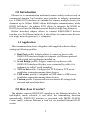
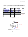
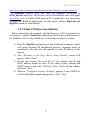
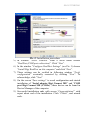
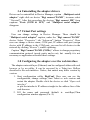
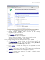
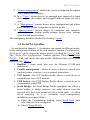
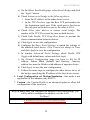
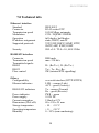
Communication adapter
RS485/422 over the Ethernet
ELO E222
User manual
ELO E222ZKE001
Table Of Content:
1.0 Introduction............................................................................ 3
1.1 Application ........................................................................ 3
2.0 How does it works?................................................................ 4
3.0 Installation.............................................................................. 4
3.1 Ethernet connection........................................................... 4
3.2 RS485/RS422 connection.................................................. 5
3.3 Power supply ..................................................................... 6
3.4 Driver installation.............................................................. 6
3.5 Virtual COM port installation............................................ 7
3.6 Uninstalling the adapter drivers ........................................ 9
3.7 Virtual Port settings ........................................................... 9
3.8 Adapter configuration over the web interface ................... 9
3.9 Serial Port profiles........................................................... 12
3.10 Setting to a RS485 mode ............................................... 14
4.0 Testing .................................................................................. 16
5.0 Troubleshooting ................................................................... 17
6.0 Ordering info........................................................................ 17
7.0 Technical info....................................................................... 18
2
ELO E222ZKE001
1.0 Introduction
Ethernet as a communication medium becomes widely used not only in
commercial domain, but becomes more popular in industry automation
too. A RS485/422 interfaces are intended to connect multiple devices for
distances up to 1600m; RS485 allows half-duplex communication, while
RS422 full-duplex. An adapter E222 allows to integrate the RS485 or
RS422 devices into the Ethernet network thereby bridge long distances.
Bellow described adapter allows to connect RS485/RS422 devices
together over the Ethernet network; it also allows to connect more devices
to a single network gateway (i.e. computer).
1.1 Application
This communication device altogether with supplied software allows
setting up following profiles:
1) Real Port profile. Adapter allows to connect a device with
RS485/422 interface straight to computer via Ethernet protocol
with virtual port application installed on,
2) Serial Bridge profile. Adapter connects two devices with
RS485/422 interfaces like they were connected by cable; it is
technique so called “serial tunneling”
3) TCP socket profile. Configured as TCP client or TCP server,
establishes connection among these devices
4) UDP socket profile. Configured as UDP client or UDP server,
establishes connection among these devices.
5) Custom profile. Experienced user can access all settings both
network and serial interfaces.
2.0 How does it works?
The adapter converts RS485/422 signaling to the Ethernet interface. In
half-duplex mode selected, it can drive the transmitting direction
automatically. RS485/422 interface is presented with DB9M (D-SUB,
Canon, male), whereas Ethernet is lead out via standard Ethernet RJ-45
socket.
3
ELO E222ZKE001
Adapter can operate with half/full duplex with maximal bitrate 230kbps.
The Ethernet layer can communicate with 10 and 100Mbps.
It should be considered, that data stream can be packetized and possible
delayed because of the nature of the Ethernet and its anticollision
mechanism.
3.0 Installation
This chapter describes the adapter E222 installation process. The
process is divided to two sub-processes - software and hardware
installation.
3.1 Ethernet connection
Adapter meets IEEE 802.3 specification and is to be plugged in to the
network with straight UTP cable. When connecting two devices together,
the cross-over cable should be used instead.
For the first time, the adapter is configured to acquire IP address from
DHCP server, so in the network must be such a service to dedicate IP
address (e.g. AP – access point, router...). It can be later changed to the
fixed IP address.
4
ELO E222ZKE001
3.2 RS485/RS422 connection
A DB9M (D-SUB 9 pin Male) connector is wired as shown on Pic. 1.
The brief description of the signal names is given in Tab. 1.
Signal
Abbrev.
DB9M
Direction
Transmitted Data +
Mode
Tx+
2
OUT
Transmitted Data -
Tx-
7
OUT
Received Data +
RxTx+
3
IN
Received Data -
RxTx-
8
IN
Data +
RxTx+
3
OUT/IN
Data -
RxTx-
8
OUT/IN
RS485
Ground
GND
5
-
Both
RS422
Tab. 1: DB9M Pin description
Tx+
Rx+ / RxTx+
GND / GND
Rx- / RxTxTx-
RS485/RS422 connector - front view
Pic. 1
5
ELO E222ZKE001
The operation mode can be selected by DIP-switches located near the
Power connector. Their meaning is shown on the converter's labels, and
on the Pic. 2.
Pic. 1: DIP-switch description
Switch No. 1 switches between RS485 and RS422 mode.
No. 2 enables passive termination of the Rx bus when in
RS422 mode or of the all RS485 bus
No. 3 nad 4 - active terminator when in RS485 mode
No. 5 enables passive termination of the Tx bus @ RS422
mode
Rx and Tx activity is indicated by LED indicators.
3.3 Power supply
The adapter can be powered with DC voltage source (range 9 to 24V)
with DC connector (outer/inner diameter is 5.5/2.1 mm), inner pin should
have positive polarity. The adapter can be powered via DB9M connector
too – positive is pin No.9, negative (ground) is pin No.5. Powered status is
indicated with green LED. The adapter is secured against the polarity
change.
3.4 Driver installation
The adapter's configuration software can operate on computers under
Operation systems both MS Windows and Linux/Unix, but only Windows
software is enclosed. Supported are version from Win98 to Win7.
Unix/Linux software can be downloaded from following address:
6
ELO E222ZKE001
http://www.digi.com/support/productdetl.jsp?pid=2469&osvid=0&s=54&tp=1
A RealPort drivers you can find on supplied CD-ROM in
E220_drivers directory. The drivers can be downloaded from web pages
www.elo.cz too. If virtual COM port on PC is applicable, it is neccessary
to install the RealPort application. In other cases, utilities DigiConf and
DigiWiz would be used instead.
3.5 Virtual COM port installation
When connected to the network, and link device to a PC is required, it is
neccessary to install Virual Port application. Bellow described process is
for Windows XP, for other Windows version the procedure is similar.
1) Start the DigiWiz application on the dedicated computer, which
will guide throuhgt all installation process; computer must be
connected to the network and capable to reach IP address of the
adapter.
2) The „Welcome to the Digi device Setup Wizard” screen will
appear. Click “Next”
3) On the next screen “Discover Device” the adapter with IP and
MAC address should be seen. If not, check power, cabling and
DHCP service, and click “Refresh” then. Check off the adapter
and click “Next”.
4) Window “Configure Network Settings” appears. Leave DHCP or
set fixed IP address,mask and gateway. Click “Next”.
7
ELO E222ZKE001
Pic. 2: Installation procedure
5) In window “Select scenario” from a scroll menu choose
“RealPort (COM port redirection)”. Click “Next”.
6) In the window “Configure RealPort Settings” (see Pic. 3) choose
“Install Digi RealPort on this computer” and click “Next”.
7) These settings can be verified in following window “Verify
configuration” eventually corrected by clicking “Next”. To
acknowledge, click “Next”
8) On the screen “Save settings” is saved configuration and started
installation of “Serial adapter Digi Connect ME” and “COM
port Digi Connect ME (COMx)”; these device can be found in
Device Manager of the computer.
9) Successful installation ends with screen “Congratulation!” with
report about end of the installation. Click “Finish”, and wizard
ends.
8
ELO E222ZKE001
3.6 Uninstalling the adapter drivers
Driver can be uninstalled in Device Manager, caption „Multiport serial
adapter” right click on device “Digi connect Wi-ME”, in menu select
“Uninstall”. After this procedure the devices “Digi connect ME” from
captions “Ports (COM & LPT)” and “Multiport serial adapter”
disappear.
3.7 Virtual Port settings
User can change settings in Device Manager. There should be
“Multiport serial adapter” caption, under the “Digi connect Wi-ME”
device. Select “Properties”, tab “Advanced”, button ”Properties”. Here
user can change a device name, COM port, IP address and port (assign
device with IP address to the COM port; you can list all devices in the
network by clicking “Browse”), enable ciphering.
Caption “Digi Connect Wi-ME (COMx)” allows to change proprietary
communication protocol (speed, parity and so on), but usually it is not
necessary as application overrides these settings.
3.8 Configuring the adapter over the web interface
The adapters network layer (Ethernet) can be configured either with web
browser or by an utility. It can be accessed by a Telnet too. Bellow
described is the web-interface. Notice, that entries may differ version by
version.
1. Start configuration utility DigiConf. Here user can see the
configuration, change settings, start Telnet or web session and
restart the adapter. Double click the device or click “Open web
interface”
or put the interface's IP address straight to the address line of the
web-browser.
2. Fill the name and password (default is: root/dbps).Then
configuration window appears (Pic. 4).
9
ELO E222ZKE001
Pic. 3: Configuration window of the LAN interface
3. Startup window “Home” offers overview of the settings
and there is link to tutorial too.
4. A ”Network” section contains:
IP Settings – IP address assignment
Network Services Settings – offers some network services
Advanced Network Settings – other settings
Every settings change must be confirmed with “Apply” button.
5. A “Serial Ports” section allows to set up device profile as
described in chapter 3.9. User can choose among RealPort,
TCP/UDP sockets, Serial bridge and others.
6. In a “GPIO” section the setting are not applicable for this
adapter.
7. “Alarms” can be set if either any GPIO inputs state combination
comes or required pattern in serial data flow appears.
8. “System” section stores network ID strings – adapter's name,
administrator contact..
10
ELO E222ZKE001
9. “Remote management” enables the remote configuring the adapter
with Connectware Manager
10. In a “Users” section can be be managed user approved to login
and configure the adapter and assigned different rights for every
user.
11. A “Management” section shows active configuration and allows
some changes to that. It depends on chosen profile.
12. “Administration” section allows to customize web interface,
update firmware, backup profile settings, factory reset, settings
overview and remote reboot.
The configuring should be finished by clicking “logout”.
3.9 Serial Port profiles
As mentioned in chapter 1.1, the adapter can operate in different modes.
In the configuration window of the web interface, section “Configuration \
Serial ports” can be chosen the proper mode by clicking the “port n” link.
The “Serial Port Configuration“ window appears. Click the “Change
Profile...” link, and choose the right profile. Additional info can be found
under the link “More...”:
1. RealPort – maps serial port over the Ethernet (COM port
redirection).
2. Console management – allows to access a device's console port
(such as routers, switches.) over a network connection.
3. TCP Sockets - the TCP Sockets Profile allows a serial device to
communicate over a TCP network
4. UDP Sockets - the UDP Sockets Profile allows a serial device to
communicate using UDP
5. Serial Bridge - the Serial Bridge Profile configures one side of a
serial bridge. A bridge connects two serial devices over the
network as if they were connected with a serial cable – so called
Serial tunneling. As it is commonly used configuration,
installation procedure follows:
a) Under the Configuration heading, select Serial Ports, then
select the port to be configured.
b) Select Change Profile....
11
ELO E222ZKE001
c) On the Select Port Profile page, select Serial Bridge and click
the “Apply” button.
d) Check Initiate serial bridge to the following device.
Enter the IP Address of the other device server.
In the TCP Port box, type the Raw TCP port number for
the destination serial port. If the serial port is the first or
the only port on the device server, the value is 2101.
e) Check Allow other devices to initiate serial bridge. The
number of the TCP Ports must be same on both devices.
f) Check both Enable TCP Keep-Alive boxes to prevent the
freeze communication between devices.
g) Click Apply to save the configuration.
h) Configure the Basic Serial Settings to match the settings of
the attached serial device. Flow Control set always to None
and click Apply to save the configuration.
i) In window Advanced Serial Settings check Enable RTS
Toggle with default min. values and click Apply.
j) On Network Configuration page you have to fill fix IP
address, Subnet Mask (default) and Gateway. Gateway
address box must be filled in with address of opposite device.
k) Click Apply to save the new configuration.
l) Follow the same steps to configure the other device server of
the bridge, specifying the IP address of the first device server.
6. Local Configuration and Modem Emulation - this mode is not
applicable for this adapter (only RS232).
7. Custom - the Custom Profile is an advanced option to allow full
configuration of the serial port.
Keep in mind, once you configure the adapter to the Serial Bridge, you
will be able to configure the adapter over the LAN
No More!!
If needed so, the factory reset must be done!
12
ELO E222ZKE001
3.10 Setting to a RS485 mode
It is necessary to setup the properties of the serial port when COM port
emulation is used in half duplex mode.
Following procedure is effective for Microsoft Windows:
Open Device Manager, expand “Multiport serial adapter” caption,
right click on the “Digi connect ME” device. Select “Proper-ties”, tab
“Advanced”, button ”Properties”. The "Advanced proper-ties" window
appears (Pic. 5)
Pic. 4: Properties of the serial adapter
Click "Custom settings" and on the popup window (Pic. 6) check
choice "Always Use RTS Toggle for Flow Control ”
13
ELO E222ZKE001
Pic. 5: Popup window
Confirm all the windows with "OK" button and close the Device
Manager. Settings for half duplex RS485 is done.
4.0 Testing
Plug the adapter to the Ethernet network. Power up the adapter. After a
second should light up an orange indicator LNK (close to the Ethernet
socket).. In a minute should LNK indicator (orange) light on. If not, the
cable may be defective or improper wired (when connecting to the
endpoint like PC – you should use cross-over UTP cable, in other cases
use straight UTP cable) or power supply is not good or module might be
damaged. In a while the green indicator ACT starts blinking indicating a
network traffic. Make sure drivers are installed (see chap. 3.5). Start
DigiWiz. application from supplied CD-ROM and click “Next” to
discover the adapter. If it appears in the window, installation was
successful. Finish the DigiWiz application (click “Next”). See the port
number in Device Manager. Set up the RS422 with DIP switch and
connect loopback to the RS422 port (connecting Tx and Rx together) and
run the Autotest application from the installation CD-ROM. Fill up the
port number and click “Start data transfer”. If everything is O.K, the
message “Data transferred successfully” appears; while if not, the error
message “Timeout on Device Read” will be seen.
14
ELO E222ZKE001
For testing purpose can be helpful a HyperTerminal, which is part of the
operating system MS Windows.
5.0 Troubleshooting
Symptom
Solution
The LNK indicator does not
come up
Check power supply polarity, voltage
Check Ethernet status and cable
LNK lights, but cannot locate
adapter in computer
Check PC network settings
Everything works but serial
connection
Check a serial cable
Check if the serial port installed in
Device Manager
Check adapter configuration,
especially serial interface
Check proper termination
configuration (depends on application)
6.0 Ordering info
Ordering code is ELO E222
The adapter is delivered with installation CD-ROM and this manual.
Serial cable with DB9 connectors is an optional accessory and must be
ordered separately. Please include the cable length and connector type in
the order then.
15
ELO E222ZKE001
7.0 Technical info
Ethernet interface
Standard
Connector
Transmission speed
Modulation
Operation
IP address assignment
Supported protocols
Security
RS485/422 interface
Connector
Transmission speed
Transmitted signals:
RS485
RS422
Flow control
Others
Configurability
Ethernet indicators
RS485/422 indicators
Power indicator
Power supply
Current consuption
Dimensions (WxLxH):
Storage temperature
Operating temperature
Humidity
IEEE 802.3
RJ-45 socket UTP
10/100 Mbps, automatic
CCK / DQPSK / DBPSK
full duplex, half duplex
static, DHCP, auto IP
TCP, UDP, DHCP, SNMP, HTTP,
SMTP, ARP, ICMP, IGMP
SSL v3.0 / TLS v1.0, AES 128bit
DB9 male
max. 230 kb/s
D+ (Rx/Tx+), D- (Rx/Tx-)
Tx+, Tx-, Rx+,RxSW (internal RTS signalling)
over web interface (HTTP/HTTPS)
LNK – orange (Link)
ACT – green (Activity)
Tx – orange (Trasmit)
Rx – green (Receive)
PWR – green
9-24V DC
150mA at 12V
80 x 120 x 25 mm
- 10 .. +55 °C
+ 0 .. +50 °C
0 – 95% (non-condensing)
16
ELO E222ZKE001
17