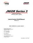
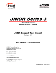
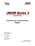
1
JNIOR Series 3
A Network I/O Resource
Utilizing the JAVA™ Platform
Serial-to-Ethernet Manual
Release 3.0
NOTE: JNIOR OS 3.1 or greater required
INTEG Process Group, Inc.
2919 East Hardies Rd, First Floor
Gibsonia, PA 15044
PH (724) 933-9350
FAX (724) 443-3553
www.integpg.com
[email protected]
© 2001 – 2009 INTEG Process Group, Inc.
All Rights Reserved
Last updated on: March 23, 2009
INTEG Process Group, Inc.
TABLE OF CONTENTS
1
2
3
4
5
6
7
What is the Serial-to-Ethernet Function?.................................................................... 3
The Purpose of the Serial-to-Ethernet Function ......................................................... 3
Connecting the Serial Device...................................................................................... 3
Activating the Serial-to-Ethernet Software................................................................. 5
Configuring the Serial-to-Ethernet Software .............................................................. 6
How to Test and Use the Serial-to-Ethernet Software................................................ 8
Options...................................................................................................................... 10
JNIOR A Network I/O Resource
Serial-to-Ethernet Manual – Release 3.0
2
INTEG Process Group, Inc.
1 What is the Serial-to-Ethernet Function?
The Serial-to-Ethernet function for the JNIOR is a software application that runs on the
JNIOR and allows the JNIOR to act as a converter between a serial device connected to
the JNIOR and a remote application communicating to the JNIOR via the Ethernet
network using TCP/IP. The serial to Ethernet conversion is bi-directional meaning that
the serial device can communicate to the PC and the PC can communicate to the serial
device. The JNIOR acts as a converter in between the serial device and the PC sending
and receiving packets of information between the two devices.
2 The Purpose of the Serial-to-Ethernet Function
The Serial-to-Ethernet function can be used for a variety of applications and adds value to
these applications when compared to standalone serial converters because of the digital
and analog I/O available with the JNIOR. The user can integrate new and legacy serial
devices into their application as well as utilize the JNIOR I/O.
3 Connecting the Serial Device
The default port for connecting the serial device is the Auxiliary Serial port located along
the top edge of the JNIOR. (Please see “Section 7 – Options” of this manual for using
the “RS-232 only” serial port located along the lower edge of the JNIOR.) There are two
different physical connection types available for the Auxiliary Serial port. JNIOR model
number JNR-100-003A has a 5-pin connector and JNIOR model number JNR-100-003B
has a DB9 connector. For both models, the auxiliary serial port can communicate via
RS232, RS422 or RS485. The mode is configured via jumpers internal to the JNIOR.
The default jumper setting is RS232.
The following information is from the drawing titled – JNIOR Model 310 Connections &
Mounting – on the CD supplied with your JNIOR. To modify the communication mode,
you must remove the four screws on the JNIOR and remove the lid. The jumpers are
located in the upper right corner. Pin number 1 is closest to the outside of the box. The
internal jumper settings are as follows:
Mode
RS-485 2-Wire Half Duplex – Terminated
RS-485 2-Wire Half Duplex – Not Terminated
RS-422/RS-485 4-Wire Terminated
RS-422/RS-485 4-Wire Not Terminated
RS-232 (default setting since January 1, 2008)
JNIOR A Network I/O Resource
Serial-to-Ethernet Manual – Release 3.0
J15
1–2
1–2
2–3
2–3
2–3
J16
1–2
1–2
2–3
2–3
2–3
J17
1–2
2–3
1–2
2–3
2–3
3
INTEG Process Group, Inc.
Auxiliary Serial Port DB9 Connector
For JNIOR model number JNR-100-003B, the serial device is connected to the DB9
connector using a standard, straight through serial cable. The pin connections are as
follows:
Pin 1 – No connection
Pin 2 – RS232 (TX) / RS485 (TX-)
Pin 3 – RS232 (RX) / RS485 (RX-)
Pin 4 – No connection
Pin 5 – Ground
Pin 6 – No connection
Pin 7 – RS232 (RTS) / RS485 (RX+)
Pin 8 – RS232 (CTS) / RS485 (TX+)
Pin 9 – No connection
Auxiliary Serial Port 5-Pin Connector
For JNIOR model number JNR-100-003A, the serial device is connected to the 5-pin
connector as follows, where pin 1 is closest to the center of the JNIOR box:
Pin 1 – Ground
Pin 2 – RS232 (TX) / RS485 (TX-)
Pin 3 – RS232 (RTS) / RS485 (TX+)
Pin 4 – RS232 (RX) / RS485 (RX-)
Pin 5 – RS232 (CTS) / RS485 (RX+)
JNIOR A Network I/O Resource
Serial-to-Ethernet Manual – Release 3.0
4
INTEG Process Group, Inc.
4 Activating the Serial-to-Ethernet Software
The Serial-to-Ethernet software is pre-installed on all JNIORs. A back-up copy is
provided on the JNIOR CD. To activate the software so that it runs on boot up, please
launch the main JNIOR web page, go to the Applications tab and check the Serial-toEthernet Converter box. When finished, click the Save button and you will be asked if
you want to reboot the JNIOR now. Please click “Yes” (if you are ready) and the JNIOR
will reboot. After the reboot, the Serial-to-Ethernet software will be running.
JNIOR A Network I/O Resource
Serial-to-Ethernet Manual – Release 3.0
5
INTEG Process Group, Inc.
5 Configuring the Serial-to-Ethernet Software
Once the Serial-to-Ethernet program is running, it will be ready to accept clients on the
default Ethernet TCP/IP port of 9201. The default setting for the serial port is 9600 baud,
8 data bits, 1 stop bit, no parity and flow control set to none. What this means is that the
serial device connected to the JNIOR serial port must work with the above serial settings
otherwise you will have to change the settings on either the JNIOR or your device. Any
application running on a PC or other remote device that wants to interact with the serial
device connected to the JNIOR via the Ethernet using TCP/IP will need to make a
connection to the JNIOR using port 9201. This port can also be changed.
The Registry Editor tab on the JNIOR Main Web page can be used to change any settings
for the Serial-to-Ethernet software program. After you enable the Serial-to-Ethernet
program and it is running after a reboot, the default settings are displayed in the Registry
Editor and are as shown below:
JNIOR A Network I/O Resource
Serial-to-Ethernet Manual – Release 3.0
6
INTEG Process Group, Inc.
The Registry Keys with their full name and default settings that you can edit are as
follows (please ignore any other registry keys as they are for system operation):
AppData/TCP_to_Serial/Baud = 9600
AppData/TCP_to_Serial/DataBits = 8
AppData/TCP_to_Serial/FlowControl = 0
AppData/TCP_to_Serial/PacketSize = 1024
AppData/TCP_to_Serial/Parity = 0
AppData/TCP_to_Serial/Port = 9201
AppData/TCP_to_Serial/SerialPort = AUX
AppData/TCP_to_Serial/StopBits = 1
To modify any of the above keys, click on the appropriate key in the Registry Editor
window and then the Edit Key button. Make any changes and click the Save button.
The valid settings are as follows:
Key Name
Baud
Default
9600
Valid Settings
300, 600, 1200, 2400,
4800, 9600, 19200,
38400, 57600, 115200
7 or 8
0, 1, or 2 where:
0 = none
1 = CTS/RTS (hardware)
2 = XON/OFF (software)
From 1 to 1024 bytes
0, 1, or 2 where:
0 = no parity
1 = odd parity
2 = even parity
DataBits
Flow
Control
8
0
Packet Size
Parity
1024
0
Port
9201
Serial Port
AUX
Any valid TCP port not
already used
AUX or RS232
StopBits
1
1 or 2
JNIOR A Network I/O Resource
Serial-to-Ethernet Manual – Release 3.0
Comments
No reboot required
No reboot required
No reboot required
No reboot required
No reboot required
Supports:
8 databits, 1 stop bit
7 databits, 2 stop, no parity
7 databits, 1 stop, with parity
The JNIOR must be rebooted for
this change to take effect.
Reboot required – defines the serial
port on the JNIOR that the serial
device is connected to. (Please see
Section 7 of this manual for
important information.)
No reboot required
7
INTEG Process Group, Inc.
6 How to Test and Use the Serial-to-Ethernet Software
After the Serial-to-Ethernet software is running and properly configured, you may be able
to test the connection to your serial device using a program such as HyperTerminal. The
test will only work if your serial device either puts out serial packets unsolicited or can
receive commands from a program such as HyperTerminal.
To connect to the Serial-to-Ethernet application via the Ethernet (TCP/IP) using
HyperTerminal, set it up using a TCP/IP (Winsock) connection and enter port 9201 and
your JNIOR IP Address. The screen shot below shows the HyperTerminal set-up.
Once connected, you will see the word Connected appear on the Hyper Terminal screen
followed by any prompt or data coming from your serial device. You can now interact
with your serial device as if it were connected via the serial cable directly to your PC.
An example of a good connection as viewed from Hyper Terminal is as follows:
JNIOR A Network I/O Resource
Serial-to-Ethernet Manual – Release 3.0
8
INTEG Process Group, Inc.
NOTE: Only one client (PC application or other service coming in through the Ethernet
port) can be connected to the Serial-to-Ethernet application at a time. When a connection
is attempted while another client is already connected, a string is returned telling you the
IP Address of the client already connected. An example of a connection attempt when
someone else is already connected and the message displayed in HyperTerminal is as
follows:
Third Party Packages
Third party packages, such as Serial/IP Redirector from Tactical Software can be used
between your program running on a PC and the JNIOR serial server running on the
JNIOR. The set-up screen for Serial/IP Redirector would look as shown below where the
server IP address is your JNIOR IP Address and the port is the port you are using with
9201 being the default.
JNIOR A Network I/O Resource
Serial-to-Ethernet Manual – Release 3.0
9
INTEG Process Group, Inc.
7 Options
The default setting for the Serial-to-Ethernet software is to utilize the Auxiliary Serial
port located along the top edge of the JNIOR. However, it is possible to change this
setting to utilize the RS-232 serial port located along the bottom edge of the JNIOR. It is
important to understand that the primary purpose of the RS-232 port is to act as the
command console for the JNIOR. The command console allows the user to connect to
the JNIOR via a program such as HyperTerminal for configuration purposes. And
although they are not visible to the user unless connected, the JNIOR will write certain
system messages to this port.
If you desire to use this port for your serial device, then you must start the Serial-toEthernet software as described above so that the Registry Keys are displayed. Using the
main JNIOR web page, edit the SerialPort key and change the value to RS232. You must
reboot the JNIOR (a soft reboot via the About tab or a Telnet window is preferred) and
when it finishes, the Serial-to-Ethernet software will now use the RS-232 port.
IMPORTANT: Every time the JNIOR reboots, it waits 1 minute before taking over the
RS-232 port for the Serial-to-Ethernet application. This would allow you some time to
connect to the JNIOR via HyperTerminal for an emergency where you no longer knew
the JNIOR IP address and had no other way to connect to the JNIOR. You would have 1
minute to log in and type ‘ps’ at the prompt to list all the running processes and then type
‘kill X’ where X is the process number for the serialethernet.jnior program.
The program will stop immediately and you will have time to change your ipconfig or go
to the Command Line registry editor and delete the Run key for the Serial-to-Ethernet
software program. When the Run key is deleted, the program will no longer
automatically run after boot.
NOTE: You can have both Serial-to-Ethernet and Serial Control (see the Serial Control
Manual) running on the same JNIOR at the same time as long as they are using different
serial ports. You must start the application first that will be using the RS232 port and
change its default setting from AUX to RS232. Then you can start the other application
because it will now be able to run and use the Auxiliary Serial port. Having both
programs running at the same time with both of them configured for the Auxiliary Serial
port could cause unexpected operation of your JNIOR.
JNIOR A Network I/O Resource
Serial-to-Ethernet Manual – Release 3.0
10
INTEG Process Group, Inc.
Summary
Thank you for purchasing the JNIOR. Hopefully this manual made the getting-to-know process of
your new JNIOR very quick and easy. The JNIOR has many more wonderful tools and features
available, and are explained in detail in the supplied documents.
Copyright
Copyright © 2001-2009 INTEG Process Group, Inc.
All rights reserved.
Notice
Every effort was made to make this manual as accurate and useful as
practical at the time of the writing of this manual. However, all information is
subject to change.
Trademarks
Trademarks are the property of their respective holders.
Sun, Sun Microsystems, the Sun logo and Java are trademarks or
registered trademarks of Sun Microsystems, Inc. in the United States and
other countries.
Microsoft, Windows, MS-DOS and Internet Explorer are registered
trademarks of Microsoft Corporation.
HyperTerminal is a registered trademark of Hilgraeve, Inc.
Use Restrictions
This User’s Manual and the software contained in the JNIOR are
copyrighted by INTEG Process Group, Inc. and may not be copied or
reproduced without prior consent from INTEG Process Group, Inc. INTEG
Process Group, Inc. is not responsible for any errors or omissions that may
be contained in this manual.
Please do not hesitate to contact our JNIOR team at INTEG Process Group, Inc. We can be
reached via phone, fax or e-mail as follows:
INTEG Process Group, Inc.
2919 E. Hardies Road
1st Floor
Gibsonia, PA 15044
www.integpg.com
[email protected]
PH (724) 933-9350 extension 20
FAX (724) 443-3553
JNIOR A Network I/O Resource
Serial-to-Ethernet Manual – Release 3.0
11