1
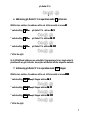
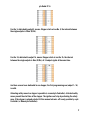
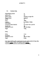
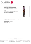
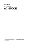
=
éíñ=o~Çáç=f`=NS=
j~åì~ä=
j~åì~ä=
1
ptx Radio IC 16
aÉ~ê=ÅäáÉåí=
aÉ~ê=ÅäáÉåí=
=
Thank you very much for buying the German engineered ptx system.
system We are very pleased you
made the decision to use our products.
Pyrotronix Show Control Systems assures you state of the art equipment with components
designed for reliable performance indoor and outdoor. The rugged components of the ptx
system offers the firework-designer enormous set up possibilities as well as an easy and
simple work flow from the show script till the set up.
Please note that all manual as well as all screen displays, keyboard layouts, hardware
descriptions or software are subjects to copyrights and other intellectual property rights of
PYROTRONIX Show Control Systems GmbH, Germany.
© August 2012 PYROTRONIX Show Control Systems GmbH, Germany, all rights reserved.
ptx Radio IC 16
Content
1.
2.
3.
4.
5.
6.
7.
8.
9.
10.
General Safety Instructions ................................................................................................. 4
Description ........................................................................................................................... 5
Handling ............................................................................................................................... 5
Battery .................................................................................................................................. 6
Addressing ........................................................................................................................... 6
Addressing ptx Radio IC 16 in operation mode IC ignition box .......................................... 7
Addressing ptx Radio IC 16 in operation mode STEP Stepper ............................................ 7
Frequency setting .............................................................................................................. 10
Ignition................................................................................................................................ 10
Technical Data: .................................................................................................................. 11
ptx Radio IC 16
1. General Safety Instructions
The correct order of setting up and connecting ptx system is mandatory for every user in order to
achieve the highest degree of safety. At the beginning of the setting up process please ensure that the
control panel key is with the responsible person.
ptx system must only be operated with original equipment and accessories manufactured by Pyrotronix
Show Control Systems, Germany. The use of non-original equipment may result in the malfunction of the
ptx system.
system Misuse of the ptx system may lead to property damage or personal injury. The ptx system is
designed for professional use only.
Professional fireworks/pyrotechnic operators shall only use the system in a controlled professional
environment permitted by the authority having jurisdiction. ptx system shall only be used to ignite
pyrotechnics and fireworks. Connecting components or effects to the system is only allowed, when no
power source is connected to the system whenever you are setting up, connecting or adding
components or effects.
This also applies to every kind of work with fireworks/pyrotechnic devices.
Before using ptx system and effects in public places, the necessary notifications/ permissions must be
obtained from the responsible authorities. When working in close proximity to people, staging, scenery
or similar things it is very important that safety standards be closely followed. Familiarity with, staging,
scenery, or similar things is necessary to maintain appropriate safety standards.
Smoking and open flames or lights shall be banned in the pyrotechnic/fireworks area. You shall be
familiar with the fire alarm, detection and suppression systems.
Observe the safety instructions in this manual. Observe the safety instructions of the
fireworks/pyrotechnic effects and respect the recommend safety distances. The operating technician
must have an unrestricted view to the firing position as well as to the whole fireworks/pyrotechnic area.
Never put your face or other parts of your body over fireworks/pyrotechnic effects with armed ignition
boxes. Maintain the appropriate distance of separation for the effect or firework being used when ptx
Ignition System gets powered.
The specific procedures pertaining to the use and operation of the ptx Ignition System are outlined in the
user manual. Deviation from any of the procedures outlined in this manual are specifically forbidden and
not recommended by Pyrotronix GmbH. Any deviations to the procedures as outlined in the user manual
may result in property damage or personal injury.
Any deviations to the procedures as outlined in the user manual is considered a misuse of the system
and done so at your own risk.
PYROTRONIX Show Control Systems GmbH Germany cannot be held responsible for any harm caused by
the misuse, improper electrical connection, failure to properly maintain, improper handling of
pyrotechnics and fireworks or deviation from the procedures outlined in ptx system user manual.
4
ptx Radio IC 16
2. Description
ptx Radio IC 16 is a radio ignition box with 16 outputs. Setting the address and the
frequency is possible with 3 turn switches at the front of the box.
A stepper function with 16 different intervals can be programmed.
ptx Radio IC 16 is equipped with a separate battery pack, equipped with a powerful Li- Ion
battery. By using ptx Radio IC 16 with the associated battery pack, it is not allowed to
connect other additional power supply units (like ptx MFB, ptx RM) on plug DATA OUT.
ptx Radio IC 16 can be used as well as a radio or cable device.
ptx system is a bidirectional system, with a ptx Controller all outputs can be programmed,
tested and ignited ( s. manual of ptx Controller).
3. Handling
On top of the box there are the 16 output terminals and 1 antenna socket, in front the 3 turn
switches to set the address, 1 turn switch to set the frequency and two plugs, DATA IN and
DATA OUT, to connect the box with other ptx devices. With full charged battery it is possible
to connect 3 more ptx IC 16 - or 1 more ptx IC 48 (Data OUT). One red LED shows the status
ARMED. By using ptx Radio IC 16 with the associated battery pack, it is not allowed to
connect other additional power supply units (like ptx MFB, ptx RM...) on plug DATA OUT.
The seperate battery pack is eqipped with a display to control the battery capacity and a
plug to connect with the ptx Radio IC 16.
5
ptx Radio IC 16
4. Battery
ptx Radio IC is equipped with a separate battery case.
Set the battery to the left side of the ptx Radio IC and save the case with a carabiner.
Connect the plug of the battery with ptx Radio IC.
The LED at the battery case is an indicator of battery capacity, press the switch on top of
the battery case, the led shows the battery capacity.
LED green flashing
=
battery max
LED green
=
100%
LED orange
=
70%
LED red
=
40%
LED red flashing
=
10%
Charging the battery is possible with the associated ptx charger.
5. Addressing
Setting the address is possible by 3 turn switches. Up to 200 different addresses are
available.
Additional to the address the function of the box can set with the left turn switch.
2 different features are availble:
Ignition box, every single output can be programmed, adjustment IC.
Stepper, started by one impulse and running in a definite interval, adjustment
STEP.
6
ptx Radio IC 16
6. Addressing ptx Radio IC 16 in operation mode IC ignition box
With the turn switches, the address will be set, left turn switch is in zone IC.
IC
* switch setting IC 001 =
ptx Radio IC 16 , address Nr. 1
* switch setting IC 011 =
ptx Radio IC 16, address Nr. 11
* switch setting IC 111 =
ptx Radio IC 16, address Nr. 111
(*left to the right)
Up to 200 different addresses are selectable. Programming of every single output is
possible with any ptx Controller, description will be find into the respective manuals.
7. Addressing ptx Radio IC 16 in operation mode STEP Stepper
With the turn switches, the address will be set, left turn switch is in zone STEP.
STEP
* switch setting STEP 001 = ptx Stepper address Nr. 1
* switch setting STEP 011 = ptx Stepper address Nr. 11
* switch setting STEP 111 = ptx Stepper address Nr. 111
(*left to the right)
7
ptx Radio IC 16
Up to 200 different Stepper addresses are selectable.
16 different intervals can be programmed. Duration of the interval depends on the
positioning of the cue No. (start time).
Adjustable intervals:
Different intervals are settable by positioning of the programmed cue No.
Ignition starts always from output 1 and is running to output 16.
The picture below shows a ptx IC 16, every interval is assigned to an output.
Cue No. 1, dedicated to output 5, means: Stepper starts at cue No. 1, the interval between
the single outputs is 600ms (0,6s).
Next example: Cue No. 1, dedicated to output 11, means: Stepper starts at cue No. 1, the
interval between the single outputs is 80ms (0,08s).
8
ptx Radio IC 16
Cue No. 5, dedicated to output 5, means: Stepper starts at cue No. 5, the interval between
the single outputs is 20ms (0,02s).
Cue No. 24, dedicated to output 16, means: Stepper starts at cue No. 24, the interval
between the single outputs is 0ms (0,00s), all 16 outputs ignite at the same time.
Are there several cues dedicated to one stepper, the first programming cue (output 1- 16)
is valid.
Allocating safety zones to a stepper is possible (s. manual ptx Controller). Activated safety
zones prevent the start time of the stepper. The ignition can’t stop by activating the safety
zone, if the stepper is already started. At this moment a break- off is only possible by a ptx
Controller (s. Manual ptx Controller).
9
ptx Radio IC 16
8. Frequency setting
With the turn switch on front of the box it is possible to set the frequency.
There are 16 different possibilities, 0 – F.
9. Ignition
Is the ptx IC 16 ready for ignition – controlled by any ptx Controller- , the red LED at the
right side of the case will light on.
10
ptx Radio IC 16
10.
Technical Data:
Outputs/Outgoing channel
Ignition power
Ignition capacity
Stepper function
Interval
Range
Frequency
Radio channel
Connected ptx boxes (Data Out)
Stand by time
Dimension (L x H x B)
Weight
16
33V
40 igniter per output, 30Ω
integrated
16
1000m
0- E 869MHz, F 915MHz
16
max. 3 ptx IC 16 or 1 ptx IC 48
10h
280 x 140 x 80mm
1,06kg
Battery
Battery
Charge time
Dimension (L x H x B)
Weight
Li-Ion
4h
280 x 55 x 25mm
0,65kg
From August 1, 2011 we offer a new frequency for some countries outside of Europe. New
frequency is 915MHz, setting is with frequency switch, position F.
From this day all ptx radio devices will be delivered with this setting.
11