1
Quanta Hardware
Instruction Manual
Version 2.01
INTELLIGENT LIGHTING CONTROLS, INC.
5229 Edina Industrial Boulevard
Minneapolis. Minnesota 55439
Phone 612 829 1900
FAX 612 829 1901
1-800-922-8004
ILC Quanta 1000 User’s Manual
Table of Contents
Section 1 How Do I.......?
1.0 Section Overview...........................................................................
1.1 If Nothing Seems To Work..............................................................
1.2 To Check The Status Of A Relay Output.....................................
1.3 To Change The Time The Lights Go Out .....................................
1.4 To Change a Holiday Date ..........................................................
1.5 Add a Relay to a Switch Group ..................................................
1-1
1-2
1-3
1-4
1-5
1-6
Section 2 System Description
2.0 Section Overview...........................................................................
2.1 Controller Architecture .................................................................
2.1.4 I/O Board(s) ...........................................................................
2.1.5 Programming Module ..........................................................
2.1.6 Lighting Relays.......................................................................
2.1.7 Controller Capacity..............................................................
2.2 System Features .............................................................................
2.2.2 Switch Types ..........................................................................
2.2.4 Time Based Scheduling........................................................
2.2.5 Holidays..................................................................................
2.2.6 Blink Alert................................................................................
2.2.7 Run Time Monitoring.............................................................
2.2.8 Telephone Control ................................................................
2.2.9 Networking and Global Control .........................................
2-1
2-1
2-2
2-3
2-3
2-3
2-11
2-11
2-11
2-12
2-12
2-14
2-14
2-14
Section 3 Additional Operations
3.0 Section Overview...........................................................................
3.1 Pre-Installation Checks ...................................................................
3.2 Mounting The Controller.................................................................
3.2.1 Location .................................................................................
3.2.3 Environmental Considerations ..............................................
3.2.4 Distance From Control Devices ............................................
3.2.5 Remote Lighting Relays .........................................................
3.2.6 ILC-128 Distance ....................................................................
3.2.7 Phone Line..............................................................................
3.3 Wiring The Controller.......................................................................
3.3.1 Wiring the Controller's Transformers ......................................
3.3.2 Connecting Line and Load ..................................................
3.3.3 Wiring Switch Inputs ...............................................................
3.3.4 Wiring Remote Relays - Wire any remote mounted relays.
3.3.5 ILC-128 Expansion Panels ......................................................
3.3.6 Auxiliary Contacts..................................................................
3-1
3-1
3-1
3-1
3-1
3-2
3-2
3-2
3-2
3-2
3-3
3-3
3-3
3-4
3-4
3-4
ILC Quanta 1000 User’s Manual
3.4 Pre-Power Checks ..........................................................................
3.4.1 Check for Correct Voltage On Transformer Secondaries...
3.4.2 Verify Controllers Supply Voltage..........................................
3.4.3 Double Check Connections.................................................
3.4.4 Verify Lighting The Relays ......................................................
3.5 Power-up and Checkout ...............................................................
3.5.1 Power-up the Controller........................................................
3.5.2 Perform Initial Programming Procedures .............................
3.5.3 Verify the Switching Function ................................................
3.5.4 Verify the Timer Functions......................................................
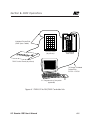
3.5.5 Verify Remote Communications Link ...................................
3.6 Troubleshooting...............................................................................
3.6.1 Controller Will Not Power-Up.................................................
3.6.2 Lighting Relay(s) Will Not Function........................................
3.6.3 Switch Input Will Not Function...............................................
3.6.4 Timers Will Not Function Properly ..........................................
3.6.5 An Entire I/O Board(s) Doesn't Work .....................................
3.6.6 Remote Communications Doesn't Work..............................
3-8
3-8
3-8
3-8
3-8
3-8
3-9
3-9
3-9
3-9
3-9
3-10
3-10
3-10
3-10
3-11
3-11
3-12
Section 4 Initial Programming Procedures
4.0 Section Overview...........................................................................
4.1 Programming Worksheets .............................................................
4.1.1 Complete the Relay Output Worksheet ............................
4.1.2 Complete The Switch Input Worksheet ...............................
4.1.3 Timer Programming Worksheet ............................................
4.1.4 Holiday Worksheets ...............................................................
4.2 Keypad & Screen Description .......................................................
4.2.1 Home Screen............................................................................
4.2.2 Screen Time Out/Auto Data Save.......................................
4.2.3 Special Keystrokes .................................................................
4.3 Programming Procedures..............................................................
4-1
4-1
4-2
4-5
4-7
4-5
4-9
4-9
4-9
4-9
4-9
Section 5 Additional Programming Operations
5.0 Section Overview...........................................................................
5.1 Programming Daylight Savings Time Variables ..........................
5.2 Programming The Power ON Settings ........................................
5.3 Programming The Timer Output Type .........................................
5.4 Astro Clock Operations.................................................................
5.6 Displaying The Controller Switch Inputs Status ..........................
5.7 Displaying Relay Output Status ....................................................
5.8 Displaying Current Firmware Revision .........................................
5.9 Resetting The Controller ................................................................
5-1
5-2
5-4
5-5
5-6
5-10
5-11
5-12
5-13
ILC Quanta 1000 User’s Manual
Section 6 Communications and Networking
6.0 Section Overview ..........................................................................
6.1 On site Communications Via On-Board Modem ......................
6.1.1 Requirements ........................................................................
6.1.2 Procedure ..............................................................................
6.2 Remote Communications Via On-Board Modem.....................
6.2.1 Requirements ........................................................................
6.2.2 Procedure ..............................................................................
6.3 RSX Communication Options .......................................................
6.3.1 RS232 Operation ...................................................................
6.3.2 RS485 Operation/Networking .............................................
6.3.3 Network Architecture ...........................................................
6.3.4 Installation/Checkout Procedures ......................................
6.4 LAN Up-Grade................................................................................
6.5 Global Events/Holidays .................................................................
6.6 LAN Network Limits.........................................................................
6.6 Telephone Switching .....................................................................
6-1
6-1
6-1
6-1
6-3
6-3
6-3
6-5
6-5
6-10
6-10
6-10
6-12
6-13
6-13
6-16
Section 7 Global Module Programming
7.0 Section Overview...........................................................................
7.1 Global Module Keypad/Screen ..................................................
7.2 Configuring the LAN ......................................................................
7.3 Setting The Global Module Clock ...............................................
7.4 Programming Global Events ........................................................
7.5 Programming Holidays ..................................................................
7.6 Setting Astro-Clock Variables .......................................................
7-1
7-1
7-2
7-3
7-3
7-10
7-11
Section 8 DMX Programming
8.0 Section Overview...........................................................................
8.1 Control Concepts ..........................................................................
8.2 Programming Procedures.............................................................
8-1
8-1
8-2
ILC Quanta 1000 User’s Manual
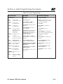
Figures
Figure
Figure
Figure
Figure
Figure
Figure
Figure
Figure
Figure
Figure
Figure
Figure
Figure
Figure
Figure
Figure
Figure
Figure
Figure
Figure
Figure
Figure
Figure
Figure
Figure
Figure
Figure
Figure
Figure
Figure
Figure
Figure
Figure
Figure
Figure
Figure
Figure
Figure
Figure
Figure
1-1, Override Switches on I/O Board .....................................
2-1, Quanta 1000 Relay Controller.........................................
2-2a, CPU Board Detail............................................................
2-2b, CPU Board Detail (RSX Unit) ..........................................
2-3, I/O Board Detail ................................................................
2-4, Programming Module Detail ...........................................
2-5, Quanta 1000-ILC-128 Link ................................................
3-1, CPU Board Detail ..............................................................
3-2, I/O Board Detail ................................................................
3-3, Controller To Expansion Panel Cabling ..........................
4-1, Sample Relay Output Worksheet ....................................
4-2, Sample Switch Input Worksheet......................................
4-3, Sample Timer Worksheet ..................................................
4-4, Sample Holiday Worksheet ..............................................
4-5, Programming Module With Home Screen.....................
4-6, Configure Controller I/O ..................................................
4-7, Clock Set Programming ...................................................
4-8, Switch Programming Screen ...........................................
4-9, Timer Programming...........................................................
4-10, Holiday Programming.....................................................
5-1, Daylight Savings ................................................................
5-2, Power On Settings.............................................................
5-3, Timer Output Type ............................................................
5-4, Astro-Clock Variables........................................................
5-5, Astro-Timer Programming.................................................
5-6, Switch Input Status............................................................
5-7, Displaying Relay Output Status .......................................
5-8, Displaying Firmware Revision...........................................
5-9, Controller Reset .................................................................
6-1, Direct Connect Modem Link ...........................................
6-2, Remote Modem Link ........................................................
6-3, RSX Controller CPU Board ................................................
6-4, Direct Connected RSX Controller ...................................
6-5, Phone/Modem Connected RSX Controller...................
6-6, RS485 Network ...................................................................
7-1, Global Module Screen/Keypad......................................
7-2, LAN Configuration Screen ...............................................
7-3, Global Switching ...............................................................
7-5, Global Event, Phone Code .............................................
7-6, Holiday Screen ..................................................................
ILCEDIT-Q User’s Manual
1-2
2-5
2-6
2-7
2-8
2-9
2-10
3-5
3-6
3-7
4-3
4-4
4-6
4-8
4-10
4-12
4-13
4-14
4-16
4-17
5- 3
5- 4
5- 5
5-7
5-9
5-10
5-11
5-12
5-13
6-2
6-4
6-7
6-8
6-9
6-11
7- 1
7- 2
7- 7
7- 9
7-10
Section 1– How Do I…?
Figures, continued
Figure
Figure
Figure
Figure
8-1,
8-2,
8-3,
8-4,
DMX-512 to RSX/DMX Controller Link..............................
DMX Address Configuration ............................................
Setting DMX Signal Levels ................................................
Programming DMX Switch Inputs....................................
8-3
8-5
8-7
8-9
Table 2-1, Programmable Switching..................................................
Table 4-1, Special Keystrokes..............................................................
Table 4-2, Configure Controller ..........................................................
Table 4-3, Set The Clock ......................................................................
Table 4-4, Programming Switch Inputs ..............................................
Table 4-5, Timer Programming............................................................
Table 4-6, Holiday Programming........................................................
Table 5-1, Daylight Savings .................................................................
Table 5-2, Power ON Settings .............................................................
Table 5-3, Timer Output Type..............................................................
Table 5-4, Astro-Clock Variables.........................................................
Table 5-5, Astro Timer Programming ..................................................
Table 5-6, Switch Input Status .............................................................
Table 5-7, Relay Output Status ...........................................................
Table 5-8, Current Firmware Revision.................................................
Table 5-9, Controller Reset ..................................................................
Matrix 6-1, Maximum LAN Nodes.......................................................
Table 7-1, Global Event Programming, Global Switching .............
Table 7-2, Global Event Programming, Timer ..................................
Table 7-3, Global Event Programming, Phone Code .....................
Table 8-1, Configure The DMX Addresses .........................................
Table 8-2, Setting The DMX Signal Levels .........................................
Table 8-3, DMX Switch Input Programming ......................................
2-13
4-11
4-12
4-13
4-14
4-15
4-17
5-2
5-4
5-5
5-6
5-8
5-10
5-11
5-12
5-13
6-15
7-4
7-6
7-8
8-4
8-6
8-8
Tables
ILC Quanta 1000 User’s Manual
Section 1– How Do I…?
Section 1
How Do I…?
ILC Quanta 1000 User’s Manual
Section 1– How Do I…?
ILC Quanta 1000 User’s Manual
Section 1– How Do I…?
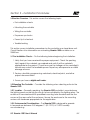
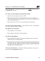
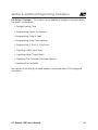
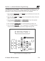
1.0 Section Overview: This section gives step-by-step instructions on how to perform common Quanta 1000 changes/maintenance tasks. To obtain the maximum benefit from this section, you should actually perform the operations as
you read them. We also recommend that you read Sections 2 and 4 before
attempting any of these procedures. Refer to Section 4 for more detail on specific operations. Section 1 will answer the following questions:
• How do I change the time the lights go out? (Section 1.3)
• How do I change a holiday date? (Section 1.4)
• How do I add a relay output to a switch group? (Section 1.5)
• How do I check the status of the relay outputs? Section 1.2)
• Nothing seems to work! How do I get the lights ON or OFF? (Section 1.1)
ILC Quanta 1000 User’s Manual
1-1
Section 1– How Do I…?
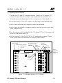
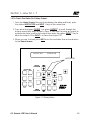
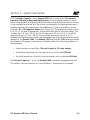
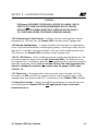
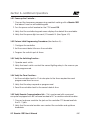
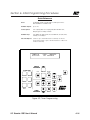
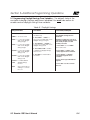
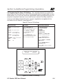
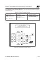
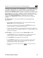
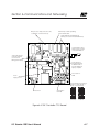
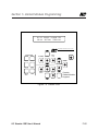
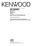
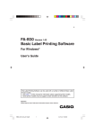
1.1 If Nothing Seems To Work 1. Locate the ON and OFF override switches. There is an ON and an OFF
switch for each relay. The switches are located on the controller I/O
board(s) and are independent of the microprocessor. (See Figure 1-1.)
2. Push each relay's ON or OFF switch to set the relay to the desired state.
3. Verify that the line side of the lighting relays are powered.
4. Verify that the controller is programmed by viewing the switch input and
timer programming.
5. Turn the power switch located on the CPU board OFF for 15 seconds and
then turn the power back ON.
6. Still not working? Call 612-829-1900 for ILC applications support. Please
have a phone by the controller for a step-by-step analysis.
Switch Inputs
24 VAC
Failsafe Override
Relay Drive
Switches
Relay
24 VAC
Status LED
Pilot Light
Switch Inputs ON LED
Switch Inputs
OFF LED
FROM MCU
OR I/O CARD
INPUTS
ON OFF
OUTPUTS
ON
COM
OFF
I/O Interconnect
Quick
Connects
to lighting
Relays
Output
ON Signal
Output
OFF Signal
POWER
ON
COM
OFF
INPUTS
16 POINT
OUTPUTS
Figure 1-1 Override Switches On I/O Board
ILC Quanta 1000 User’s Manual
1-2
Section 1– How Do I…?
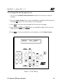
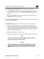
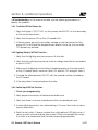
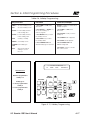
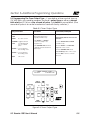
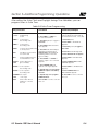
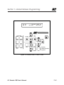
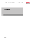
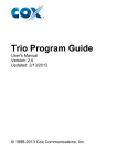
1.2 To Check The Status Of A Relay Output 1. From the Home Screen (the one that displays the date and time), press
the yellow SWITCH TYPE and INPUT ↓ keys at the same time.
2. Press either the green OUTPUT ↓ or green OUTPUT ↑ to scroll through the
outputs and check each output's status. If you want to force an output to
a particular state, scroll to the output then press the yellow INPUT ↑ key to
drive the output ON or INPUT ↓ to force the output OFF.
3. When you are finished, press QUIT or let the controller time out and return
to the Home Screen.
OUTPUT: 004
STATUS: ON
(ACTIVATE)
SWITCH
PROGRAM
CLOCK SET
EDIT
HOUR
INPUT
SWITCH
TYPE
CONTROL
TYPE
MONTH
QUIT
OUTPUT
MINUTE
DATE
DAY OF
WEEK
YEAR
EDIT
TIMER
PROGRAM
TIMER
HOUR
MINUTE
DAY
Figure 1-2 Relay Status
ILC Quanta 1000 User’s Manual
1-3
Section 1– How Do I…?
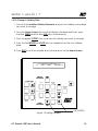
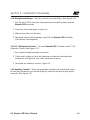
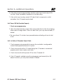
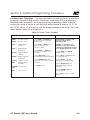
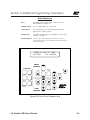
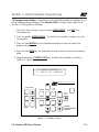
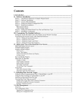
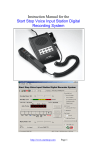
1.3 To Change The Time The Lights Go Out 1. Consult the Controller Timer Worksheet and pick the Timer you want to
change.
2. From the Home Screen ( the screen that displays the date and time), press
the blue EDIT key (in the Timer section of the keypad).
3. Press Timer↓ until you have located the timer to be changed.
4. Press the blue HOUR and MINUTE keys as required to adjust when the controller will invoke the timer.
5. Press QUIT or let the controller time out and return to the Home Screen.
TIMER: 02
OUT # 002
6:30A
MON-FRI
ON CONTROL
SWITCH
PROGRAM
CLOCK SET
EDIT
HOUR
INPUT
SWITCH
TYPE
CONTROL
TYPE
MONTH
QUIT
OUTPUT
MINUTE
DATE
DAY OF
WEEK
YEAR
EDIT
TIMER
PROGRAM
TIMER
HOUR
MINUTE
DAY
Figure 1-3 Timer Editing
ILC Quanta 1000 User’s Manual
1-4
Section 1– How Do I…?
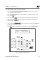
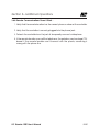
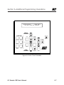
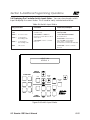
1.4 To Change A Holiday Date 1. Consult the Controller Holiday Worksheet and pick the holiday whose date
you want to change.
2. From the Home Screen (the one that displays the date and time), press
the blue TIMER↓and the blue DAY keys simultaneously.
3. Press the green OUTPUT↓ key to access the holiday you want to change.
4. Press the tan MONTH and DATE keys as needed to set the new Holiday
date.
5. Press QUIT or let the controller time out and return to the Home Screen.
<<< HOLIDAY SCHEDULE >>>
01
DATE 09/04
HOLIDAY A
SWITCH
PROGRAM
CLOCK SET
EDIT
HOUR
INPUT
SWITCH
TYPE
CONTROL
TYPE
MONTH
QUIT
OUTPUT
MINUTE
DATE
DAY OF
WEEK
YEAR
EDIT
TIMER
PROGRAM
TIMER
HOUR
MINUTE
DAY
(ACTIVATE)
Figure 1-4 Editing Holidays
ILC Quanta 1000 User’s Manual
1-5
Section 1– How Do I…?
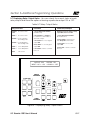
1.5 To Add A Relay Output To A Switch Group 1. Consult the Controller Switch Input Worksheet and pick the Input # you
want to add the relay output to.
2. From the Home Screen (the one that displays the date and time), press
the yellow EDIT key.
3. Press the yellow INPUT↓ key until you have scrolled to the desired Input.
4. Press the green OUTPUT↓ key until you have selected the output to be
added to the switch group.
5. Press the green CONTROL TYPE key to select how you want the added output to react to the switch signal.
6. Press QUIT or let the controller time out and return to the Home Screen.
IN # 003
OUT # 010
MAINTAIN ON/OFF
ON/OFF CONTROL
SWITCH
PROGRAM
CLOCK SET
EDIT
HOUR
INPUT
SWITCH
TYPE
CONTROL
TYPE
MONTH
QUIT
OUTPUT
MINUTE
DATE
DAY OF
WEEK
YEAR
EDIT
TIMER
PROGRAM
TIMER
HOUR
MINUTE
DAY
Figure 1-5 Editing A Switch Group
ILC Quanta 1000 User’s Manual
1-6
Section 1– How Do I…?
Notes
ILC Quanta 1000 User’s Manual
Section 2 – System Description
Section 2
System Description
ILC Quanta 1000 User’s Manual
Section 2 – System Description
ILC Quanta 1000 User’s Manual
Section 2 – System Description
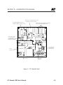
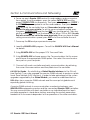
2.0 Section Overview: The Quanta 1000 is a microprocessor-based lighting controller. You can program the Quanta 1000 to control lighting relays in response
to switch signals sensed by its inputs and/or by time-based scheduling. The
Quanta 1000 is UL approved and FCC certified for both commercial and residential applications.This section covers the following:
• Quanta 1000 system architecture and capacity
• System Features
• Control and application concepts
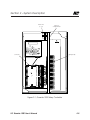
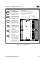
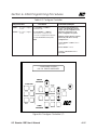
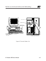
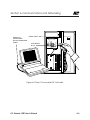
2.1 Controller Architecture - The major components comprising the controller
are: (Figure 2-1.)
•
•
•
•
•
•
enclosure
transformer(s)
CPU board
I/O board
programming module
lighting relays
2.1.1 Enclosures - The enclosure is rated NEMA 1. It is divided into a line voltage
section housing the line voltage side of the transformer(s) and lighting relays
and a low voltage section containing the Class 2 side of the lighting relays,
transformer secondaries, and electronic components. Enclosures are available
in 4 sizes to accommodate 8, 16, 24, 32, 40 and 48 inputs, outputs, and lighting
relays. The 8 relay enclosure is 15" (w) x 18" (h) x 4" (d). The remaining three sizes
are all 6 inches deep. The 16 relay size is 24" (w) x 24" (h). The 24/32 relay size
measures 24" (w) x 30" (h) and the 40/48 relay size is 30" (w) x 48" (h). The
Quanta 1000 is shipped to the job-site as a complete assembly.
2.1.2 Transformer(s) - A 40 VA control transformer (120 or 277/24 vAC provides
the 24 vAC input to power the controller electronics. A second 40 VA 120 or
277/24 vAC transformer provides class 2 switching power to the lighting relays
and the relay output status LEDs which display the ON/OFF status of each lighting relay and to any field installed pilot light switches.
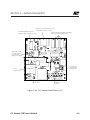
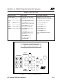
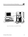
2.1.3 CPU Board - (See Figures 2-2a and 2-2b.) The CPU board provides the controller's intelligence and memory. Major components include:
ILC Quanta 1000 User’s Manual
2-1
Section 2 – System Description
• the power supply, which converts the 24 vAC input to the +5, -5 and +12
vDC required by the controller logic and communications circuits. A
power switch provides the means of energizing/de-energizing all controller
electronics.
• the Micro-processor – executes the computer code and coordinates all
controller functions including the controller real time clock.
• the PROM chip – contains the controller operating system and basic tasks.
• the static RAM chips – store the user-entered operating parameters and also
feature an internal back-up battery to protect data during power failures.
• the “super cap” – keeps the controller real time clock functioning during
power failures.
• the on-board modem – this 1200 baud modem allows for remote programming of the controller. This is the standard communications interface for
the Quanta 1000 controller.
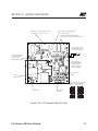
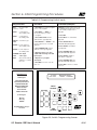
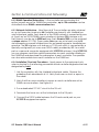
• RS485/RS232 Port – If you order the RSX option equipped Quanta 1000, this
replaces the on board modem (Figure 2-2b. If configured for RS232 communications it supports programming of the controller via a personal computer equipped with ILC programming software. If configured for RS485
communication, this supports the networking of up to 128 controllers via a
2 wire communications bus. See Section 5 for greater detail.)
• DTMF Interface – On RSX equipped controllers, this device supports touch
tone phone ON/OFF control of either individual lighting relays or of all the
relays in the controller. See Section 6 for detail.
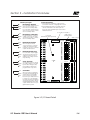
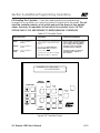
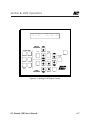
2.1.4 I/O Board(s) – See Figure 3. This board provides the electronic interface
between the switch input/timing signals and the lighting relays. The 8 relay controllers are equipped with a single board which contains eight (8) switch inputs
and (8) relay outputs. The 16, 24, 32, 40, and 48 relay enclosures are equipped
with I/O boards each containing 16 switch inputs and 16 relay outputs. The 16
relay enclosure can house one of these boards, the 32 relay enclosure two and
the 48 relay enclosure three.
ILC Quanta 1000 User’s Manual
2-2
Section 2 – System Description
• Switch inputs – can accept input from either two or three wire momentary or
maintained dry contact devices. Each input has two associated LEDs. The ON
LED lights when a closure is sensed on the ON and COMMON terminals. The OFF
LED lights when a closure is sensed on the OFF and COMMON terminals. The
inputs are noise and surge resistant. A switch may be located up to 1500 feet
from the controller, provided a minimum of 20 gauge wire is used. See Table 2-1
for available options.
• Relay Outputs – each output controls its associated lighting relay ON and OFF.
Each output has two associated LEDs. The ON LED momentarily blinks when the
output switches the relay ON. The OFF LED momentarily blinks when the output
switches the relay OFF. The outputs are noise and surge resistant. (A lighting relay
may be mounted up to 2000 feet from the controller if 18 AWG wire is used.)
• Override Switches – Each relay output is equipped with an ON and an OFF
override switch. These switches allow you to turn the associated lighting relay
ON or OFF even if the controller electronics are inactive.
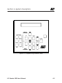
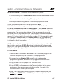
2.1.5 Programming Module – (See Figure 4.) The programming module provides
for user access to the controller. It consists of a tactile response keypad and a
two line 24 characters per line LCD display integral to Quanta 1000 controller or a
portable device temporarily connected to a programming port on the CPU
board (See Figure 2-4.) Each Quanta 1000 controller can also be programmed
via its 1200 baud modem port (or on RSX options via the RS485/RS232 port).
2.1.6 Lighting Relays – control the line voltage loads. The lighting relays can
control 120 or 277 vAC loads rated up to 20 amps. The Class 2 low voltage control
circuit of each relay is terminated to a relay output on the controller I/O board
(See Figure 2-3.) Each relay output controls only one lighting relay. Generally, the
lighting relays are resident in each controller; however, they may be remote
mounted, using 20 gauge wire, up to 2000 feet from the controller, if required by
job site application.
ILC Quanta 1000 User’s Manual
2-3
Section 2 – System Description
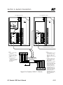
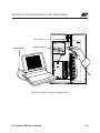
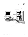
2.1.7 Controller Capacity – Each Quanta 1000 can control up to 128 switched
input and 128 relay outputs and lighting relays. If the required number of switch
inputs, relay outputs and lighting relays exceeds the quantity that can be housed
in the controller enclosure, or if the circuits controlled by the lighting relays are in
locations remote from each other, the additional I/O points and relays can be
housed in ILC-128 Expansion Panels (See Figure 2-5.) The expansion panels come
in 16, 24, 32, 40 and 48 capacities. All enclosure sizes are six (6) inches deep. The
16 relay size is 24" (w) x 24" (h) The 24/32 relay size is 24" (w) x 30" (h). The 40/48
relay enclosure is 30" (w) x 48" (h). The controller enclosures house only I/O
board(s) and lighting relays which are controlled from the microprocessor board
resident in the Quanta 1000. The Quanta 1000 and the ILC-128 expansion panels
are linked by 24 gauge, 8 conductor shielded cable. The following guide must
be observed:
• there can be no more than 128 switch inputs & 128 relay outputs.
• the distance between any two panels must not exceed 200 feet.
• the total length from the first to the last panel must not exceed 500 feet.
2.1.8 System Capacity – Up to 128 Quanta 1000 controllers equipped with the
RSX options can be linked on a 2 wire RS485 bus. See Section 6 for details.
ILC Quanta 1000 User’s Manual
2-4
Section 2 – System Description
Transformer
(1 of 2)
High/Low
Voltage Divider
SWITCH
PROGRAM
CLOCK SET
EDIT
HOUR
INPUT
SWITCH
TYPE
CONTROL
TYPE
MONTH
QUIT
OUTPUT
MINUTE
DATE
DAY OF
WEEK
YEAR
TIMER
EDIT
TIMER
PROGRAM
I/O Board
HOUR
MINUTE
DAY
Lighting Relay
FROM MCU
OR I/O CARD
INPUTS
ON OFF
OUTPUTS
ON
OFF
COM
POWER
ON
OFF
COM
INPUTS
OFF
COM
ON
OFF
COM
ON
INPUTS
OUTPUTS
16 POINT
I/O
TO NEXT
I/O CARD
OFF ON
77013300 REV A
970133
REV
OUTPUTS
Figure 2-1, Quanta 1000 Relay Controller
ILC Quanta 1000 User’s Manual
2-5
Section 2 – System Description
Microprocessor Chip (executes code,
coordinates controller functions)
On Board Keypad and Screen or
Portable Programmer plugs in here)
Static RAM with internal back-up battery
(stores User Entered Parameters)
“Super Cap” (Keeps
controller real time
clock functions
during power failure)
Phone Jack for
on board 1200
baud modem
Power
Supply Section
Power Switch
I/O Interface
Terminals
Figure 2-2a, CPU Board Detail (Base Unit)
ILC Quanta 1000 User’s Manual
2-6
Section 2 – System Description
Microprocessor Chip (executes code,
coordinates controller functions)
PROM Chip contains operating
system & basic tasks
Static RAM with internal back-up
battery (stores User Entered Parameters)
To RSi Interface Unit or
another RSX Controller
on the same branch
“Super Cap” (Keeps
controller real time
clock functions
during power failure)
18/2
RS-232 Interface
(programming port
for attachment of
ILC EDIT equipped
laptop computer
Phone Jack for
DTMF
Power
Supply Section
Communications Link Selector
(jumper for either RS-485 or
RS-232 communications)
Power Switch
I/O Interface
Terminals
Jumpered
for RS-485
Jumpered
for RS-232
Figure 2-2b, CPU Board Detail (RSX Unit)
ILC Quanta 1000 User’s Manual
2-7
Section 2 – System Description
Switch Input Types
ON
Switch Input Notes
Momentary ON/OFF:
OFF
The controlled outputs turn OFF
when Common & OFF contacts are momentarily made.
The controlled outputs turn ON
when Common & ON contacts
are momentarily made.
ON
Momentary Pushbutton:
COM.
COM.
OFF
The input turns the controlled
outputs to the opposite state
each time the switch contacts
are momentarily made.
1. Switch can be located up to 1500 feet from
I/O board if minimum of 20 guage wire is used.
2. When parallel switching, momentary switches
can be terminated to the same input. But
there must be a separate input used for each
maintained switch.
I/O Conductor Interface
Relay Output
Override Switch
Power LED
(indicated board is powered)
Quik Connect
FROM MCU
OR I/O CARD
INPUTS
ON OFF
ON
COM.
OFF
ON
ON
ON
As long as the switch is turned
ON, relay output(s) controlled
by this switch will ignore any
timers that they have been
programmed to respond to.
OFF
OFF
INPUTS
Timer Override:
COM
COM.
POWER
OFF
ON
The controlled outputs toggle
each time the input senses a
change of state. Function is
similar to line voltage 3 and 4
way switching.
COM
OFF
Maintained Multi-way:
OFF
COM.
When the input senses a
closure it turns the controlled
outputs ON. When the input
senses an open, the controlled
outputs are turned OFF.
COM
ON
OUTPUTS
ON
OFF
Maintained ON/OFF:
OFF
COM.
COM
ON
16 POINT
I/O
OUTPUTS
OFF ON
Timed ON:
When the switch is activated,
the relay outputs assigned to it
will turn ON for a selectable
period of time. Five minutes
before the specified ON time is
to expire, the controller blinks
the relay outputs as a warning.
At this point the switch can be
activated again and the relay
outputs will turn ON for the programmed time period.
INPUTS
TO NEXT
I/O CARD
77013300 REV A
970133
REV
OUTPUTS
Figure 2-3, I/O Board Detail
ILC Quanta 1000 User’s Manual
2-8
Section 2– System Description
SWITCH
PROGRAM
CLOCK SET
EDIT
HOUR
INPUT
SWITCH
TYPE
CONTROL
TYPE
MONTH
QUIT
OUTPUT
MINUTE
DATE
DAY OF
WEEK
YEAR
EDIT
TIMER
PROGRAM
TIMER
HOUR
MINUTE
DAY
Figure 2-4, Programming Module Detail
ILC Quanta 1000 User’s Manual
2-9
Section 2– System Description
ILC Lighting Controller
ILC-128 Expanion Panel
SWITCH
PROGRAM
CLOCK SET
EDIT
HOUR
MONTH
MINUTE
DATE
DAY OF
WEEK
YEAR
INPUT
SWITCH
TYPE
CONTROL
TYPE
QUIT
OUTPUT
EDIT
TIMER
TIMER
PROGRAM
HOUR
MINUTE
DAY
FROM MCU
OR I/O CARD
INPUTS
ON OFF
FROM MCU
OR I/O CARD
INPUTS
OUTPUTS
ON OFF
OFF
COM
ON
OFF
COM
OFF
COM
ON
OFF
COM
POWER
POWER
INPUTS
OFF
COM
ON
ON
OUTPUTS
ON
OFF
COM
77013300 REV A
970133
REV
OFF
ON
TO NEXT
I/O CARD
OUTPUTS
OFF ON
COM
OFF
COM
INPUTS
16 POINT
I/O
ON
ON
INPUTS
OUTPUTS
INPUTS
16 POINT
I/O
TO NEXT
I/O CARD
OUTPUTS
OFF ON
77013300 REV A
970133
REV
OUTPUTS
24/8SHIELDED
SHIELDEDCABLE
CABLE
22/8
CAROL # CO744-21-10
BLACK
BROWN
RED
ORANGE
YELLOW
GREEN
BLUE
WHITE
NOTES:
1. Color code and tag
conductors.
2. Earth ground shield on
only one end of each
cable.
3. Ensure there are no
shorts between
conductors or between
conductors and earth
ground before
power-up.
BLACK
BROWN
RED
ORANGE
YELLOW
GREEN
BLUE
WHITE
to additional Expansion Panels
Figure 2-5, Quanta 1000-ILC-128 Link
ILC Quanta 1000 User’s Manual
NOTES:
1. Overall distance of controller/Expansion Panel
network is 1000 ft. max.
Distance of any one
cable run not to exceed
200 ft.
2. A single controller can
control a max. of 128
switch inputs and 128
relay outputs
3. CAUTION: the controller
must be the first unit in
the network. Daisy chain
the I/O cable from the
controller to the first
expansion panel: then
from the first to the second panel, and so on.
Switch inputs and relay
outputs are numbered
in ascending order
beginning with the first
input and output on the
first I/O board in the
controller.
2-10
Section 2– System Description
2.2 System Features – The Quanta 1000 allows you to:
• Control relays by programming outputs to respond to switch closures
sensed on the controller switch inputs.
• Control relays by programming outputs to respond to internal timers so as
to follow a time of day schedule and program a blink alert to warn of an
impending OFF timer.
• Define holiday schedules. On a holiday, the controller will substitute a
special set of timers you have defined instead of using the timers normally
invoked for day of the week control.
• Monitor the run time of each relay output and the number of ON/OFF
cycles.
• Select the state the relays will assume when power is applied to the controller.
• Control relays via touch tone telephone commands (on RSX equipped
controllers only).
The controller also:
• automatically saves entered data in real time.
• implements a 50 msec stagger time between each relay output simultaneously impacted by ON/OFF control signals.
2.2.1 Switch Control – When you program switches, you "software patch" switch
inputs to relay output(s). Since there is no hardwired connection between the
switch inputs and relay outputs, you have unlimited flexibility in selecting the
relay outputs you wish to respond to a given switch input. You can program a
switch input to control one, all, or any number of relay outputs. You can also
program relay outputs to respond to one, several, or all of the switch inputs. If
you change your mind you can re-program the controller to re-define the
switching control.
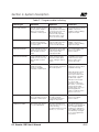
2.2.2 Switch Types – You can program each switch input as one of seven different switch types. The type you select depends on your particular application
and on the hardware characteristics of the switch or switch equivalent (photocell contact, BAS system channel, etc.) used on the project site. See Table 2-1
for an explanation of the different switch types.
ILC Quanta 1000 User’s Manual
2-11
Section 2– System Description
2.2.3 Control Types – You can program the relay outputs to respond to the
switch signal in one of the following manners:
• ON/OFF – The relay output(s) will turn ON and OFF as the switch input
senses closures and openings across its input terminals.
• ON only – The relay output(s) turn ON but NOT OFF in response to switch
input signals.
• OFF only – The relay output(s) turn OFF but NOT ON in response to
switch input signals.
• OFF With Blink Alert – See 2.2.6 for details.
2.2.4 Time Based Scheduling – The controller supports 32 timers (events) for use
in developing time of day scheduling. A timer is an ON or OFF signal generated
by the controller which turns affected outputs ON or OFF at a specific time of
day. Any or all of the 32 timers can be assigned to implement a control
schedule on one or more days of the week. Each of the 32 timers instead of
being assigned a time of day (12:30 PM etc.) may be assigned a time relative
to sunrise/sunset (Astro-Time). The choices are: one hour before sunrise, sunrise,
one hour after sunrise, one hour before sunset, sunset, one hour after sunset. The
controllers feature automatic daylight saving and leap year adjustment.
2.2.5 Holidays – Any or all of the 32 timers can be assigned to any of 32 holidays.
The controller will automatically substitute the holiday timers for the normal day
of the week timers at the appropriate date. The holiday can be programmed as
a full or half-day period. Individual timers may be programmed to ignore
Holidays or execute as normal.
2.2.6 Blink Alert – Five minutes before invoking an OFF timer, the controller can
be programmed to blink the lights twice. An ON signal from a switch controlling
the lighting relays postpones implementation of the off timer for two hours. Five
minutes before the postponed OFF timer is to be invoked, the controller will blink
the lights again. If the controller receives another ON signal, the OFF timer
occurrence will be postponed for another two hours. If the controller receives
an OFF signal from the controlling switch anytime during the two hour period,
the relays will switch OFF. Blink alert may be inappropriate for some lighting
applications.
ILC Quanta 1000 User’s Manual
2-12
Section 2– System Description
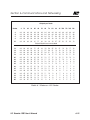
Table 2-1 Programmable Switching
Switch Type
Hardware
Operation
Comments
Momentary ON/OFF
SPDT Momentary Contact
(3 wire.) Switch wired to
ON, Common & OFF
terminals of switch input.
Input switches relay
output(s) ON when switch
closes across Common &
ON terminals. Input
switches relay output(s)
OFF when switch closes
across Common & OFF.
Momentary action permits
parallel control from
multiple locations utilizing
single switch input.
Momentary Push-button
Momentary Push-button
(2 wire) switch wired to
Common & ON terminals
of switch input
Input switches output(s) to
opposite state each time
switch closes across
Common & ON trminals.
Momentary action permits
parallel control from
multiple locations utilizing
single switch input.
Maintained ON/OFF
2 wire maintained. Switch
wired across Common &
ON terminals of switch
input.
When switch closes, relay
output(s) turn ON. When
switch opens, relay
output(s) turn OFF.
Use conventional 3 way
switches for multiple
switch locations
Maintained Multi-Way
2 wire maintained. Switch
wired across Common &
ON terminals of switch
input.
Relay output(s) toggle
each time switch input
senses change in state of
switch.
A separate switch input
must be used for each
switch location. SPST
switches are used.
Master Override
3 wire maintained. Switch
wired across ON,
Common, and OFF
terminals of switch input.
Actuated switch locks all
affected relay output(s) in
ON or OFF position.
A separate switch input
required for each location
in parallel switching.
Master Override must be
connected to a lower
switch input # than other
switch inputs controlling
the affected outputs.
Example: If switch input
#4 controls relay
output(s) 1,2,3 and you
also wish to control these
outputs with a master
override switch, then you
MUST designate the
master override as switch
input #1 or #2 or #3.
Timer Override
2 wire maintained. Wired
across the ON & Common
terminals of switch input.
As long as switch is ON,
the relay output(s)
controlled by this switch
will ignore any timers.
Use conventional 3 way
switches for multiple
switch locations
Variable Timed ON
Momentary Push-button
or 2 wire maintained
On switch activation the
output will turn on for one
of the following
programmed times: 15 min.,
30 min., 1, 2, or 6 hours.
Five minutes before the
expiration of programmed
time, the lights will blink
a warning. Actuating the
switch again will reset the
timer and keep the lights
on for the programmed
time period.
ILC Quanta 1000 User’s Manual
2-13
Section 2– System Description
2.2.7 Run Time Monitoring – The controller can store the Run Time (ON time) and
the number of ON/OFF cycles of each output for a maximum accumulated
count of 65535 minutes (about 45 days). After reaching this count, the controller
will reset the run time. You can reset the count at any time by issuing a command to the controller. The runtime information can be retrieved from the
controller and written to a file in comma delineated format for import into
spreadsheet programs.
2.2.8 Telephone Control – Controllers with the RSX option are equipped with an
on-board DTMF (touch tone telephone) interface. The operator dials the phone
number of the connected controller and issue (via telephone key presses)
ON/OFF control signals to each relay output or issue an ON/OFF command
affecting all the relays in the controller.
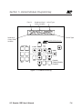
2.3.9 Networking and Global Control – RSX equipped controllers support passive
networking of up to 128 Quanta 1000 controllers. See Section 6 for details.
ILC Quanta 1000 User’s Manual
2-14
Section 2– System Description
Notes
ILC Quanta 1000 User’s Manual
Section 3 – Installation Procedures
Section 3
Installation Procedures
ILC Quanta 1000 User’s Manual
Section 3 – Installation Procedures
ILC Quanta 1000 User’s Manual
Section 3 – Installation Procedures
3.0 Section Overview - This section covers the following topics:
• Pre-Installation checks
• Mounting the controller
• Wiring the controller
• Pre-power up checks
• Power-Up & checkout
• Troubleshooting
This section covers installation procedures for the controller as a stand alone unit.
Consult Section 6 for information on networking Quanta 1000 controllers on a
RS485 bus.
3.1 Pre-Installation Checks – Do the following before beginning the installation:
1. Verify that you have received the proper equipment. Check the packing
slip(s) against the materials you ordered and verify that the material is
appropriate for the project. Check to ensure the voltages of the controller(s)
transformers match the available power. Report any discrepancies or visible
damage at once.
2. Review submittals, programming worksheets, electrical prints, and other
project documentation.
3. Ensure you have a digital multi-meter.
3.2 Mounting The Controller – Consider the following when selecting a site for the
Quanta 1000.
3.2.1 Location – Generally speaking, the Quanta 1000 controller is mounted near
the lighting panel containing the circuits to be controlled by the lighting relays. The
enclosure is manufactured with pre-drilled mounting holes located near the four
corners of the rear wall of the enclosure. Secure the enclosure to the mounting
surface with hardware appropriate for the application.
3.2.3 Environmental Considerations – The Quanta 1000 is designed to operate
in temperatures between 0-50 degrees C. (32-122 F.) & 10-90% humidity
non-condensing.
ILC Quanta 1000 User’s Manual
3-1
Section 3 – Installation Procedures
CAUTION
THE Quanta 1000 SERIES CONTROLLER IS HOUSED IN A NEMA 1 ENCLOSURE. DO NOT INSTALL IN SITUATIONS REQUIRING SPECIAL PURPOSE
ENCLOSURES OR IN AREAS WHERE THE CONTROLLER WILL BE SUBJECT
TO CONDITIONS OUTSIDE ITS DESIGNED OPERATING RANGES.
3.2.4 Distance From Control Devices – Switches & other control devices can be
located up to 1500 feet from the Quanta 1000 controller using 20 gauge wire.
3.2.5 Remote Lighting Relays – In certain situations (for example if a single branch
circuit is split and controlled by multiple lighting relays); mounting of relays remote
from the ILC controller may be convenient. You can mount a lighting relay up to
2000 feet from the Quanta 1000 controller if using 20 gauge wire.
3.2.6 ILC-128 Distance – When installing expansion panels the total distance of the
controller/expansion panel network must not exceed 500 ft. The distance of any
one segment (i.e., the distance between the controller and an expansion panel or
between expansion panels) must not exceed 200 feet. The cable required for the
network is shielded 8 conductor color coded cable. 24 gauge; CAROL cable
C0744-21-10.
3.2.7 Phone Line – If the application calls for remote communications or if the
controller is an RSX unit that is to support a phone switching application, make
arrangements for a phone outlet (RJ11) convenient to the Quanta 1000 controller.
3.3 Wiring The Controller – Perform the following procedures to wire the line and
control wiring of the Quanta 1000. Do NOT apply power to any circuits until
instructed to do so.
ILC Quanta 1000 User’s Manual
3-2
Section 3 – Installation Procedures
3.3.1 Wiring the Controller's Transformers - Wire all transformer primaries.
1. Run a dedicated 120 or 277 vAC circuit, including grounding conductor,
and terminate it to the primary of Quanta 1000 control transformer. (See
Figure 3-1.)
2. Run another 120 or 277 vAC circuit and terminate it to the primary of the
Quanta 1000 switching transformer.
3.3.2 Connecting Line and Load - Connect Line & Load Wires of the line voltage
circuits to the Lighting Relays.
3.3.3 Wiring Switch Inputs - Wire the Class 2 Switch Circuits. (See Figure 3-2.)
1. Run the required wiring between each controller & the field-installed
switches. Consult the programming worksheets & project documentation
to determine the type & quantity of required switch circuits. Check each
switch run to ensure there are no shorts between conductors or to ground.
Also verify that there are no opens.
2. Make the connections at the switch end.
3. Make the appropriate connections to the controller switch input terminals.
N0TE
REFER TO SWITCH INPUT SCHEDULE FOR LANDING WIRES TO INPUTS OR
FILL IN SWITCH SCHEDULE AS YOU PROCEED.
CAUTION
IF WIRING A SWITCH USED FOR THE MASTER OVERRIDE FUNCTION, YOU
MUST LAND THE WIRES ON A SWITCH INPUT NUMBER WHICH IS LOWER
THAN OTHER SWITCH INPUTS WHICH CONTROL THE AFFECTED RELAYS.
ILC Quanta 1000 User’s Manual
3-3
Section 3 – Installation Procedures
3.3.4 Wiring Remote Relays – Wire any remote mounted relays. (See Figure 3-2.)
1. Run the 4 #18 AWG wires (per relay) between the lighting relay and the
Quanta 1000 controller.
2. Check for shorts and opens in each run.
3. Make connections at the relay.
4. Terminate wires to selected relay output in the Quanta 1000 controller.
(Connection tool required.)
3.3.5 ILC-128 Expansion Panels – Connect Quanta 1000 Controller and ILC-128
Expansion Panels. (See Figure 3-3.)
1. Run required cable between the panels.
2. Check each cable run for shorts between conductors and between
conductors and ground. Also verify there are no opens.
3. Terminate the cable as shown in Figure 3-3.
3.3.6 Auxiliary Contacts – When using auxiliary contacts for output relay status
ensure that the device you are illuminating is wired to the relay output panel
correctly. (See Figure 3-2.)
ILC Quanta 1000 User’s Manual
3-4
Section 3 – Installation Procedures
Microprocessor Chip (executes code,
coordinates controller functions)
On Board Keypad and Screen or
Portable Programmer plugs in here)
Static RAM with internal back-up battery
(stores User Entered Parameters)
“Super Cap” (Keeps
controller real time
clock functions
during power failure)
Phone Jack for
on board 1200
baud modem
Power
Supply Section
Power Switch
I/O Interface
Terminals
Figure 3-1 CPU Board Detail
ILC Quanta 1000 User’s Manual
3-5
Section 3 – Installation Procedures
Switch Input Types
ON
Switch Input Notes
Momentary ON/OFF:
OFF
The controlled outputs turn OFF
when Common & OFF contacts are momentarily made.
The controlled outputs turn ON
when Common & ON contacts
are momentarily made.
ON
Momentary Pushbutton:
COM.
COM.
OFF
The input turns the controlled
outputs to the opposite state
each time the switch contacts
are momentarily made.
1. Switch can be located up to 1500 feet from
I/O board if minimum of 20 guage wire is used.
2. When parallel switching, momentary switches
can be terminated to the same input. But
there must be a separate input used for each
maintained switch.
I/O Conductor Interface
Relay Output
Override Switch
Power LED
(indicated board is powered)
Quik Connect
FROM MCU
OR I/O CARD
INPUTS
ON OFF
ON
COM.
OFF
ON
ON
ON
As long as the switch is turned
ON, relay output(s) controlled
by this switch will ignore any
timers that they have been
programmed to respond to.
OFF
OFF
INPUTS
Timer Override:
COM
COM.
POWER
OFF
ON
The controlled outputs toggle
each time the input senses a
change of state. Function is
similar to line voltage 3 and 4
way switching.
COM
OFF
Maintained Multi-way:
OFF
COM.
When the input senses a
closure it turns the controlled
outputs ON. When the input
senses an open, the controlled
outputs are turned OFF.
COM
ON
OUTPUTS
ON
OFF
OFF
COM.
Maintained ON/OFF:
COM
ON
16 POINT
I/O
OUTPUTS
OFF ON
Timed ON:
When the switch is activated,
the relay outputs assigned to it
will turn ON for a selectable
period of time. Five minutes
before the specified ON time is
to expire, the controller blinks
the relay outputs as a warning.
At this point the switch can be
activated again and the relay
outputs will turn ON for the programmed time period.
INPUTS
TO NEXT
I/O CARD
77013300 REV A
970133
REV
OUTPUTS
Figure 3-2 I/O Board Detail
ILC Quanta 1000 User’s Manual
3-6
Section 3 – Installation Procedures
ILC Lighting Controller
ILC-128 Expanion Panel
SWITCH
PROGRAM
CLOCK SET
EDIT
HOUR
MONTH
MINUTE
DATE
DAY OF
WEEK
YEAR
INPUT
SWITCH
TYPE
CONTROL
TYPE
QUIT
OUTPUT
EDIT
TIMER
TIMER
PROGRAM
HOUR
MINUTE
DAY
FROM MCU
OR I/O CARD
INPUTS
ON OFF
FROM MCU
OR I/O CARD
INPUTS
OUTPUTS
ON OFF
OFF
COM
ON
OFF
COM
OFF
COM
ON
OFF
COM
POWER
POWER
INPUTS
OFF
COM
ON
ON
OUTPUTS
ON
OFF
COM
77013300 REV A
970133
REV
OFF
ON
TO NEXT
I/O CARD
OUTPUTS
OFF ON
COM
OFF
COM
INPUTS
16 POINT
I/O
ON
ON
INPUTS
OUTPUTS
INPUTS
16 POINT
I/O
TO NEXT
I/O CARD
OUTPUTS
OFF ON
77013300 REV A
970133
REV
OUTPUTS
24/8SHIELDED
SHIELDEDCABLE
CABLE
22/8
CAROL # CO744-21-10
BLACK
BROWN
RED
ORANGE
YELLOW
GREEN
BLUE
WHITE
NOTES:
1. Color code and tag
conductors.
2. Earth ground shield on
only one end of each
cable.
3. Ensure there are no
shorts between
conductors or between
conductors and earth
ground before
power-up.
BLACK
BROWN
RED
ORANGE
YELLOW
GREEN
BLUE
WHITE
to additional Expansion Panels
Figure 3-3 Controller To Expansion Panel Cabling
ILC Quanta 1000 User’s Manual
NOTES:
1. Overall distance of controller/Expansion Panel
network is 1000 ft. max.
Distance of any one
cable run not to exceed
200 ft.
2. A single controller can
control a max. of 128
switch inputs and 128
relay outputs
3. CAUTION: the controller
must be the first unit in
the network. Daisy chain
the I/O cable from the
controller to the first
expansion panel: then
from the first to the second panel, and so on.
Switch inputs and relay
outputs are numbered
in ascending order
beginning with the first
input and output on the
first I/O board in the
controller.
3-7
Section 3 – Installation Procedures
3.4 Pre-Power Checks – Complete the following checks BEFORE applying power to
the Quanta 1000 controller.
3.4.1 Check for Correct Voltage On Transformer Secondaries –
1. Verify that the controller power switch is OFF.
2. After verifying that control and switching transformer source voltages are
120/277 VAC (which ever is appropriate). Power up circuits supplying control,
and switching transformers.
3. Verify that there is 120/277 VAC on the primaries of the transformer.
3.4.2 Verify Controllers Supply Voltage – Verify that there is 24 VAC on secondaries
of control & switching circuit transformers.
3.4.3 Double Check Connections –
1. Verify integrity of I/O connections
2. Verify integrity of all internal & external cabling.
3.4.4 Verify The Lighting Relays –
1. After verifying that the source is the correct voltage, power up the circuits
feeding the line of the lighting relays.
2. Switch each relay ON and OFF pushing the override switches located on the
I/O boards. There are separate ON and OFF switches for each lighting relay.
(See Figure 3-2.) Verify that the relay status LED goes ON and OFF. Verify that
the relay controls the proper circuit.
3.5 Power-up and Checkout – Complete the following procedures to power-up
and checkout the Quanta 1000 controller.
ILC Quanta 1000 User’s Manual
3-8
Section 3– Additional Operations
3.5.1 Power-up the Controller –
1. Connect the temporary programming module if working with a Quanta 1000
that doesn't have an on board keypad.
2. Turn the power switch located on the CPU board ON.
3. Verify that the controller keypad screen displays the default time and date.
4. Verify that the power light on each I/O board is lit. (See Figure 3-2.)
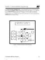
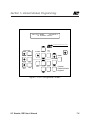
3.5.2 Perform Initial Programming Procedures (See Section 4.) –
1. Configure the controller.
2. Set the correct date & time on the controller.
3. Program the switch inputs & timers.
3.5.3 Verify the Switching Function –
1. Operate each switch.
2. Verify that each switch controls the correct lighting relays in the manner you
have programmed.
3.5.4 Verify the Timer Functions –
1. Set the controller clock to 10 minutes prior to the times required for each
programmed timer to occur.
2. Verify that the relays respond as programmed.
3. Reset the controller clock to the correct date & time.
3.5.5 Verify Remote Communications Link – This is performed with a personal
computer equipped with ILC software located at ILC or another remote location.
1. Connect a phone cord into the jack on the controller CPU board and into
the RJ-11 jack.
2. Verify that the remote location can contact the controller and up/down
load data.
ILC Quanta 1000 User’s Manual
3-9
Section 3– Additional Operations
3.6 Troubleshooting –In the event of trouble, use the following procedures to
identify the problem
3.6.1 Controller Will Not Power-Up –
1. Verify that there is 120/277 VAC on the primary and 24 VAC on the secondary
of the control transformer.
2. Verify that the power LED on the I/O board(s) is lit.
3. If there is proper primary & secondary voltage on the transformer but the
power LED is not lit and the keypad screen doesn't come up, the controller
CPU board may be bad.
3.6.2 Lighting Relay(s) Will Not Function –
1. Verify that the lighting relay has power on its line side.
2. Verify that the switching transformer has line voltage and that the secondary
output is 24 VAC.
3. Make sure that lighting control wiring is landed properly on the relay output
of the I/O board. (blue is common, red is ON, black is OFF, orange is status.)
4. Override the affected relay ON/OFF with the override switches located on
the I/O board.
5. If the relay doesn't respond replace the relay.
3.6.3 Switch Input Will Not Function –
1. Check your programming.
2. Verify proper connections at field and controller end.
3. Verify that there is only one maintained switch connected per input.
4. Unhook field connections from affected input. Connect test switch of same
type as field switch.
5. Work the test switch. Observe whether the switched input LED lights when it
senses a switch closure and the relay output LED(s) momentarily flash when
the switch is actuated and that the relays respond appropriately.
ILC Quanta 1000 User’s Manual
3-10
Section 3– Additional Operations
6. If the relays respond appropriately and the switch input and output LEDs
function, there is probably a problem in the field wiring.
7. If the switch input or relay output LEDs don't flash in response to switch
actuation, the I/O board may be bad.
3.6.4 Timers Will Not Function Properly –
1. Check your programming.
2. Verify that affected relay output LEDs momentarily flash at the times lighting
relays are to change state. If the LEDs don't flash, you may have a bad I/O
board.
3. Be sure at least 10 minutes have passed before activating a timer to start
a test.
3.6.5 An Entire I/O Board(s) Doesn't Work –
1. Check programming especially to ensure the controller is configured to
control the required number of I/O points.
2. Check to ensure that the I/O cable linking the I/O boards is connected
properly and is free of opens and shorts.
3. Check to ensure that the power LED on the I/O board is lit.
4. If the I/O board is cabled correctly and programmed correctly but still
doesn't function, you may have a bad I/O board.
ILC Quanta 1000 User’s Manual
3-11
Section 3– Additional Operations
3.6.6 Remote Communications Doesn't Work –
1. Verify that the remote location has the correct phone number of the controller.
2. Verify that the controller is securely plugged into the phone jack.
3. Detach the controller from the jack & temporarily connect a telephone.
4. If the remote location can call the telephone, the problem may be a bad CPU
board. If the remote location can't connect with the phone, something is
wrong with the phone line.
ILC Quanta 1000 User’s Manual
3-12
Section 3– Additional Operations
Notes
ILC Quanta 1000 User’s Manual
Section 4– Initial Programming Procedures
Section 4
Initial Programming Procedures
ILC Quanta 1000 User’s Manual
Section 4– Initial Programming Procedures
ILC Quanta 1000 User’s Manual
Section 4– Initial Programming Procedures
4.0 Section Overview – This section covers basic programming procedures
performed prior to or at the time of initial system start-up. You are strongly
encouraged to conduct them in the order that they are discussed. Topics
covered in this section are:
• Filling Out Programming Worksheets
• Keypad and Screen Description
• Configuring The Controller
• Setting The Controller Clock
• Programming The Switch Inputs
• Programming The Timers
• Programming The Holidays
Additional Programming procedures are covered in Section 5. Programming
procedures related to RSX equipped controllers and the optional Global Module
Controller are covered in Section 6 & 7.
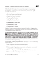
4.1 Programming Worksheets – BEFORE attempting to install the Quanta 1000 you
MUST fill out the programming worksheets. The worksheets allow you to detail the
project and control strategy you wish to implement. This will speed programming,
minimize error, and rework and ensure that you have specified switches and provided sufficient I/O points to accomplish your control objectives. There are separate worksheets for relay output, switch input, timer, and holiday programming.
Each of the four worksheet forms includes explanations of the parameters and
concepts involved in programming.
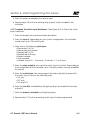
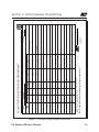
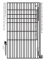
4.1.1 Complete The Relay Output Worksheet – (See Figure 4-1) To fill out the relay
output worksheet:
1. Enter the project name and controller description.
2. Enter the relay #. Depending on your system configuration, the controller
could have up to 128 relay outputs.
3. Enter the voltage type, either 120 vAC or 277 vAC, for the relay output.
4. Enter the circuit controlled by the relay output.
ILC Quanta 1000 User’s Manual
4-1
Section 4– Initial Programming Procedures
5. Enter the area controlled by the relay output.
6. Repeat steps 2-5 for the remaining relay outputs to be included in the
controller.
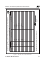
4.1.2 Complete The Switch Input Worksheet – (See Figure 4-2) To fill out the switch
input worksheet:
1. Enter the project name and controller description.
2. Enter the input #. Depending on your system configuration, the controller
could have up to 128 switch inputs.
3. Enter one of the following input types:
• Momentary On/Off
• Momentary push-button
• Maintained On/Off
• Maintained multi-way
• Master override
• Timer override
• Variable timed On – 15 minutes, 30 minutes, 1,2, or 6 hours.
4. Enter the relay output(s) you want the switch input to control. Depending on
the configuration of the controller, up to 128 relay outputs may be available
for control.
5. Enter the control type. You can program the relay output(s) to respond to
the switch input in one of the following ways:
• ON only
• OFF only
• ON and OFF
6. Enter the circuit(s) controlled by the lighting relays terminated to the relay
output(s).
7. Enter the area(s) controlled by the lighting relays.
8. Repeat steps 2-7 for the remaining switch inputs to be programmed.
ILC Quanta 1000 User’s Manual
4-2
ILC Quanta 1000 User’s Manual
VOLTAGE TYPE
(120/277)
120
120
120
277
277
277
277
277
277
RELAY #
(1-128)
1
2
3
4
5
6
7
8
9
HIA-6
HIA-5
HIA-4
HIA-3
HIA-2
HIA-1
LIA-3
LIA-2
LIA-1
SAMPLE WORKSHEET
CIRCUIT CONTROLLED
NOTE: Duplicate this form to document all Switch Input Control.
EXAMPLE
PROJECT:
Main Entrance
Lobby
Office Corridor-West
Office Corridor-East
Office Corridor-South
Office Corridor-North
Restroom-Women
Restroom-Men
5229 Edina Industrial Boulevard
Minneapolis. Minnesota 55439
Phone 612 829 1900
FAX 612 829 1901
1-800-922-8004
INTELLIGENT LIGHTING CONTROLS, INC.
Reception Area Track Lighting
AREA CONTROLLED
CONTROLLER/PANEL:
Quanta Lighting Controller Relay Output Worksheet
Section 4– Initial Programming Procedures
Figure 4-1, Sample Relay Output Worksheet
4-3
VOLTAGE TYPE
(120/277)
CIRCUIT CONTROLLED
NOTE: Duplicate this form to document all Switch Input Control.
RELAY #
(1-128)
PROJECT:
5229 Edina Industrial Boulevard
Minneapolis. Minnesota 55439
Phone 612 829 1900
FAX 612 829 1901
1-800-922-8004
INTELLIGENT LIGHTING CONTROLS, INC.
AREA CONTROLLED
CONTROLLER/PANEL:
Quanta Lighting Controller Relay Output Worksheet
ILC Quanta 1000 User’s Manual
Maintained ON/OFF
Maintained ON/OFF
Maintained ON/OFF
Maintained ON/OFF
Maintained ON/OFF
Maintained ON/OFF
Maintained ON/OFF
Maintained ON/OFF
Maintained ON/OFF
Maintained ON/OFF
Maintained ON/OFF
Maintained ON/OFF
Maintained ON/OFF
Maintained ON/OFF
3
4
5
6
7
8
9
10
11
12
13
14
15
16
SAMPLE WORKSHEET
14
13
12
11
10
9
8
7
6
5
4
3
2
1
15,16
1,2,3,4,5,6,7,8,9,10
ON/OFF
ON/OFF
ON/OFF
ON/OFF
ON/OFF
ON/OFF
ON/OFF
ON/OFF
ON/OFF
ON/OFF
ON/OFF
ON/OFF
ON/OFF
ON/OFF
ON/OFF
ON/OFF
RELAY OUTPUTS CONTROLLED (1-128) & CONTROL TYPE
NOTE: Duplicate this form to document all Switch Input Control.
Maintained ON/OFF
2
Master Override
1
EXAMPLE
INPUT TYPE
INPUT#
(1-128)
PROJECT:
CONTROLLER: CENTER 1-N.W.
5229 Edina Industrial Boulevard
Minneapolis. Minnesota 55439
Phone 612 829 1900
FAX 612 829 1901
1-800-922-8004
INTELLIGENT LIGHTING CONTROLS, INC.
Security Garage
Security Hub
Central Restrooms
Campus Restrooms
Corridor to Hub
Corridor-Northeast
Corridor-Northwest
Corridor-Southeast
Corridor-Southwest
Corridor-Center
Corridor-West
Corridor-East
Corridor-North
Corridor-South
All Corridors
All Corridors
AREA CONTROLLED
Quanta 1000 Controller Switch Input Worksheet
Section 4– Initial Programming Procedures
Figure 4-2, Sample Switch Input Worksheet
4-4
INPUT TYPE
RELAY OUTPUTS CONTROLLED (1-128) & CONTROL TYPE
NOTE: Duplicate this form to document all Switch Input Control.
INPUT#
(1-128)
PROJECT:
CONTROLLER:
5229 Edina Industrial Boulevard
Minneapolis. Minnesota 55439
Phone 612 829 1900
FAX 612 829 1901
1-800-922-8004
INTELLIGENT LIGHTING CONTROLS, INC.
AREA CONTROLLED
Quanta 1000 Controller Switch Input Worksheet
.
Section 4– Initial Programming Procedures
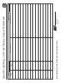
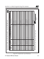
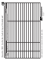
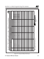
4.1.3 Timer Programming Worksheet – (See Figure 4-3.) The Quanta 1000 can
implement up to 32 Timers. To fill out the timer worksheet:
1. Enter the project and controller description.
2. Enter the Timer # (1-32).
3. Enter the time of day you want the timer to activate.
4. Enter the relay output(s) you want the timer to turn ON.
5. Enter the relay output(s) you want the timer to turn OFF or OFF with Blink
Alert.
6. Select the day(s) of the week or holiday type specifying when the controller
is to implement the timer. (If desired, flag the timer to ignore holidays)
Choices are:
• a single week day (ie. Sunday, Monday, Tuesday etc.)
• Monday-Friday
• Saturday-Sunday
• All (7) days of the week
• Holiday A, Holiday B
7. Repeat steps 2-6 for the remaining timers.
ILC Quanta 1000 User’s Manual
4-5
ILC Quanta 1000 User’s Manual
S M T W TH F S
Holiday A or B
Duplicate this form to document all Timers.
Enter the “Astro Offset Time” (in 15 min. increments) in the “Timer Time” field, if the relay group is to be
turned ON or OFF based on Sunrise or Sunset rather than a specific time of day.
NOTES:
5229 Edina Industrial Boulevard
Minneapolis. Minnesota 55439
Phone 612 829 1900
FAX 612 829 1901
1-800-922-8004
INTELLIGENT LIGHTING CONTROLS, INC.
S M T W TH F S
Holiday A or B
5,9,7,11
S M T W TH F S
Holiday A or B
16
11:30 PM
10
5,9,7,11
S M T W TH F S
Holiday A or B
S M T W TH F S
Holiday A or B
8:00 AM
9
11,12
S M T W TH F S
Holiday A or B
15
9:30 PM
8
9,10
S M T W TH F S
Holiday A or B
S M T W TH F S
Holiday A or B
8:30 PM
7
7,8
S M T W TH F S
Holiday A or B
14
7:30 PM
6
5,6
S M T W TH F S
Holiday A or B
S M T W TH F S
Holiday A or B
6:30 PM
5
1-4
S M T W TH F S
Holiday A or B
13
5:30 PM
4
1-4
S M T W TH F S
Holiday A or B
S M T W TH F S
Holiday A or B
DAY(S) OF WEEK
ALL DAYS
SAT & SUN
HOLIDAY A OR B
CONTROLLER: CENTER 1-N.W.
S M T W TH F S
Holiday A or B
5:30 AM
3
9-12
CONTROLLER
RELAY OUTPUT(S)
OFF WITH BLINK
(1-128)
12
5:00 AM
2
5-8
CONTROLLER
RELAY OUTPUT(S)
OFF
(1-128)
SAMPLE WORKSHEET
S M T W TH F S
Holiday A or B
4:00 AM
1
CONTROLLER
RELAY OUTPUT(S)
ON
(1-128)
EXAMPLE
11
TIMER TIME
TIMER#
(1-32)
PROJECT:
Quanta 1000 Lighting Controller Timer Worksheet
Section 4– Initial Programming Procedures
Figure 4-3, Sample Timer Worksheet
4-6
CONTROLLER
RELAY OUTPUT(S)
ON
(1-128)
CONTROLLER
RELAY OUTPUT(S)
OFF
(1-128)
DAY(S) OF WEEK
ALL DAYS
SAT & SUN
HOLIDAY A OR B
CONTROLLER:
5229 Edina Industrial Boulevard
Minneapolis. Minnesota 55439
Phone 612 829 1900
FAX 612 829 1901
1-800-922-8004
INTELLIGENT LIGHTING CONTROLS, INC.
CONTROLLER
RELAY OUTPUT(S)
OFF WITH BLINK
(1-128)
Quanta 1000 Lighting Controller Timer Worksheet
TIMER TIME
PROJECT:
TIMER#
(1-32)
NOTES:
Enter the “Astro Offset Time” (in 15 min. increments) in the “Timer Time” field, if the relay group is to be
turned ON or OFF based on Sunrise or Sunset rather than a specific time of day.
Duplicate this form to document all Timers.
Section 4– Initial Programming Procedures
4.1.4 Holiday Worksheets – (See Figure 4-4.) You can program the controller to
implement up to 32 Holidays. On the holiday date, the controller will substitute
either the Type A or Type B Holiday Timers for the Timers normally invoked on that
date. To fill out the holiday programming worksheet:
1. Enter the project and controller descriptions.
2. Enter the description or name of the holiday.
3. Enter the holiday date.
4. Indicate whether the holiday is Type A or B.
5. Fill in the timer #(s). These will be either the Type A or B Timers you developed on the timer programming worksheet.
6. Enter any additional information or comments you feel are useful concerning the holiday.
7. Repeat steps 2-6 for the remaining holidays.
NOTE
All Timers are deactivated on a holiday date unless they are programmed to
ignore holidays. For example, timers used to turn off relays are typically programmed to ignore holidays.
ILC Quanta 1000 User’s Manual
4-7
ILC Quanta 1000 User’s Manual
MEMORIAL DAY
SUMMER VACATION
LABOR DAY
3
4
5
NOTE: Duplicate this form to document.
PRESIDENT’S DAY
2
9/5/94
6/22/94
5/30/94
2/21/94
1/1/94
NEW YEAR’S DAY
1
1, 2
3, 4
12
1, 2
1, 2
SEE TIMER SCHEDULE
TIMERS USED
SAMPLE WORKSHEET
HOLIDAY PERIOD
DATE
EXAMPLE
(1-32)
HOLIDAY HOLIDAY NAME
PROJECT:
A
B
A
A
A
Security OFF at 6:00 am
Security ON at 6:00 pm
Security OFF at 6:00 am
Security ON at 6:00 pm
Security OFF at 6:00 am
Security ON at 6:00 pm
Security OFF at 6:00 am
Security ON at 6:00 pm
Security OFF at 6:00 am
Security ON at 6:00 pm
COMMENTS
CONTROLLER: CENTER 1-NW
5229 Edina Industrial Boulevard
Minneapolis. Minnesota 55439
Phone 612 829 1900
FAX 612 829 1901
1-800-922-8004
INTELLIGENT LIGHTING CONTROLS, INC.
(A) OR (B)
HOLIDAY
Quanta 1000 Lighting Controller Holiday Worksheet
Section 4– Initial Programming Procedures
Figure 4-4, Sample Holiday Worksheet
4-8
NOTE: Duplicate this form to document.
(1-32)
HOLIDAY HOLIDAY NAME
PROJECT:
DATE
HOLIDAY PERIOD
SEE TIMER SCHEDULE
TIMERS USED
COMMENTS
5229 Edina Industrial Boulevard
Minneapolis. Minnesota 55439
Phone 612 829 1900
FAX 612 829 1901
1-800-922-8004
INTELLIGENT LIGHTING CONTROLS, INC.
(A) OR (B)
HOLIDAY
CONTROLLER:
Quanta 1000 Lighting Controller Holiday Worksheet
Section 4– Initial Programming Procedures
4.2 Keypad & Screen Description – The keypad and screen make up the Quanta
1000 programming module. Each Quanta 1000 programming module is either
integral to the controller or is a portable device temporarily attached to the controller during programming. The keypad is composed of tactile response single
and multi-function keys. The screen is a 2 line, 24 character per line LCD display.
4.2.1 Home Screen – Figure 4-5 shows the keypad displaying the Home screen. The
Home screen displays the current date and time. All other screens, available for
programming branch from this screen. The controller returns to this screen after a
time out period has occurred on the other screens or after you press the Quit key.
4.2.2 Screen Time Out/Auto Data Save – It is not necessary to take specific action
to save entries you have programmed into the controller. When the controller
senses a lack of keypad activity for a certain period on one of the programming
screens, it returns the system to the Home screen. This time out period varies with
the type of screen involved. The time out for switch, timer, and holiday screens is
20 seconds. The time out period for the time/date and system configuration
screens is 5 seconds. NOTE: All programming is saved in real time.
4.2.3 Special Keystrokes – You must simultaneously press certain keys to invoke
some of the controllers programming options. See Table 4-1 for a listing of these
keystrokes.
4.3 Programming Procedures – Tables 4-2 through 4-6 and Figures 4-6 through
4-10 detail initial programming procedures. It is strongly recommended that you
perform them in the following order:
• configure the controller (set the number of I/O points)
• set the controller's real time clock.
• program the switch inputs
• program the timers
• program the holidays
ILC Quanta 1000 User’s Manual
4-9
Section 4– Initial Programming Procedures
(C) 1994 QUANTA ILC 1000
FRI 8/11/95 08:04:42 PM
SWITCH
PROGRAM
CLOCK SET
EDIT
HOUR
INPUT
SWITCH
TYPE
CONTROL
TYPE
MONTH
QUIT
OUTPUT
MINUTE
DATE
DAY OF
WEEK
YEAR
EDIT
TIMER
PROGRAM
TIMER
HOUR
MINUTE
DAY
Figure 4-5 Programming Module With Home Screen
ILC Quanta 1000 User’s Manual
4-10
Section 4– Initial Programming Procedures
Table 4-1 Special Keystrokes
Function
Keystrokes
Comments
Clear Programming
HOUR/MINUTE/DAY OF
WEEK (cycle power)
Clears all entries for switches, timers, and holidays etc.
The keys must be pressed during power-up.
Configure I/O
INPUT ↑/OUTPUT ↑
Accesses screen used to enter the number of inputs
and outputs the controller is equipped with.
Program Holidays
TIMER ↓/DAY
Accesses screen used to program holidays.
Set Node Address
SWITCH TYPE/CONTROL
TYPE
Accesses screen used to set the network addresses
of a RSX equipped controller.
Baud Rate
CONTROL TYPE/QUIT
Accesses screen used to set the communications
speed of a RSX equipped controller RS485/RS232 port.
Firmware Revision
OUTPUT ↑/OUTPUT ↓
Accesses screen displaying the current controller
firmware revision.
Program Daylight Savings
INPUT ↑/TIMER ↓
Accesses screen used to program daylight savings
time variables.
Switch Input Status
SWITCH TYPE/INPUT ↑
Accesses screen displaying the current state of the
switch inputs.
Output Status/Force
SWITCH TYPE/INPUT ↓
Accesses screen displaying the current state of the
relay outputs. Outputs may be forced ON/OFF from
this screen.
Timer Output Type
SWITCH TYPE/HOUR
Accesses screen where you select the timer output
types; either blink (default) or five second Off pulse.
Power On Settings
SWITCH TYPE/OUTPUT ↓
Accesses screen used to define the state the controller
will set each output to when power is applied to the
controller. (Default is no action; relay output retains
state it was in before application/re-application of
power to the controller.
Astro Clock Settings
TIMER ↑/MINUTE
Accesses screen used to enter Astro Time variables
Ignore Holiday
SWITCH TYPE
When on the Timer Edit Screen, pressing SWITCH TYPE
will toggle the ignore holiday option.
Normal/Astro time toggle
Yellow EDIT
When on the Timer Edit screen, will toggle between
normal and Astro time
Astro Selection
HOUR
When on the Timer Edit screen and toggled to Astro
time, pressing the HOUR key will scroll through the astro
time choices.
ILC Quanta 1000 User’s Manual
4-11
Section 4– Initial Programming Procedures
Table 4-2, Configure Controller
Keys/Functions
INPUT ↑
Procedure
Comments/Example
1. Press INPUT ↑ & OUTPUT ↑
simultaneously
accesses configure
screen
OUTPUT ↑ accesses configure
screen
2. Press OUTPUT ↑ or OUTPUT ↓
until number of I/O points the
controller is equipped with appears.
3. Let controller time out or press
QUIT.
The Quanta 1000 is defaulted for
control of the minimum 8 inputs &
outputs The I/O configuration must
match the total number of I/O
points configured in the system.
Example: Assume that the controller
has 24 I/O points but is currently
configured for 8.
1. Press OUTPUT ↑ & INPUT ↑ at the
same time.
2. Press OUTPUT ↑ 2 times.
3. Let the controller time out or
press QUIT..
......CONFIGURE SYSTEM......
024 I/O POINTS INSTALLED
SWITCH
PROGRAM
CLOCK SET
EDIT
HOUR
INPUT
SWITCH
TYPE
CONTROL
TYPE
MONTH
QUIT
OUTPUT
MINUTE
DATE
DAY OF
WEEK
YEAR
EDIT
TIMER
PROGRAM
TIMER
HOUR
MINUTE
DAY
Figure 4-6 Configure Controller I/O
ILC Quanta 1000 User’s Manual
4-12
Section 4– Initial Programming Procedures
Table 4-3, Set The Clock
Keys/Functions
Procedure
Comments/Example
DAY OF WEEK sets the current
day of week
1. Press any of the keys in the
CLOCK SET sector of the keypad.
Example: Assume initial date/time is
Sat. 10/07/95 12:45 AM. You wish to
set the clock to Mon. 11/13/95 02:50 PM.
MONTH
sets the current month
2. Press DAY OF WEEK until the
correct day of the week appears.
DATE
sets the current day
of month
YEAR
3. Press MONTH until the correct
number for the month appears.
sets the current year
HOUR
sets the current hour
MINUTE
sets the current minute
In CLOCK SET sector of keypad:
1. Press DAY OF WEEK twice.
2. Press MONTH once.
4. Press DATE until the correct
day of the month appears.
5. Press YEAR until the correct
year appears.
3. Press DATE four times.
4. Press HOUR 14 times.
5. Press MINUTE 5 times.
6. Press HOUR until the correct
hour appears. Make sure the
AM/PM designation is correct.
6. Let controller time out or press
QUIT.
7. Press MINUTE until the
minute appears.
8. Let the controller time
out or press QUIT.
TIME/DATE ADJUST PROGRAM
MON 11/13/95 02:50:10 PM
SWITCH
PROGRAM
CLOCK SET
EDIT
HOUR
INPUT
SWITCH
TYPE
CONTROL
TYPE
MONTH
QUIT
OUTPUT
MINUTE
DATE
DAY OF
WEEK
YEAR
EDIT
TIMER
PROGRAM
TIMER
HOUR
MINUTE
DAY
Figure 4-7, Clock Set Programming
ILC Quanta 1000 User’s Manual
4-13
Section 4– Initial Programming Procedures
Table 4-4, Programming Switch Inputs
Keys/Functions
Procedure
Comments/Examples
EDIT
accesses input
(Yellow) screen
1. Press EDIT in the switch program
sector of the keypad.
INPUT ↑
scrolls inputs in
descending order
INPUT ↓
2. Press INPUT ↑ or INPUT ↓ to
access the input you want
to program.
Example: Program switch input 3 as
a maintained On/Off switch which
controls relay outputs 10 & 11
ON/OFF.
scrolls inputs in
ascending order
SWITCH
TYPE
sets switch type
OUTPUT ↑ scrolls outputs in
descending order
OUTPUT ↓ scrolls outputs in
ascending order
CONTROL sets output
TYPE
control type
QUIT
saves entries without
waiting for controller
time out.
1. Press EDIT
3. Press SWITCH TYPE until the
desired switch type appears.
2. Press INPUT ↓ or until IN# 003
appears.
4. Press OUTPUT ↑ or OUTPUT ↓ until
the first output to be controlled
appears.
3. Press SWITCH TYPE until
MAINTAIN ON/OFF appears.
5. Press CONTROL TYPE until the
desired control type appears.
6. Repeat steps 4 & 5 for other
outputs that are being controlled
by the input.
7. Repeat 2-6 to program
other inputs.
4. Press OUTPUT ↓ until OUT#
010 appears.
5. Press CONTROL TYPE until
ON/OFF CONTROL appears.
6. Press OUTPUT ↓ again so
that OUT# 11 appears.
7. Press CONTROL TYPE until
ON/OFF CONTROL appears.
8. Press QUIT or let the controller
time out.
8. Press QUIT or let the controller
time out.
Quick Reference
IN # 003
OUT # 010
Switch Types:
Momentary ON/OFF
Momentary Push-button
Maintained ON/OFF
Maintained Multi-Way
Master Override
Timer Override
Variable Timed On
MAINTAIN ON/OFF
ON/OFF CONTROL
SWITCH
PROGRAM
CLOCK SET
EDIT
INPUT
SWITCH
TYPE
Control Types:
HOUR
ON only
OFF only
ON/OFF
CONTROL
TYPE
MONTH
OUTPUT
MINUTE
DATE
DAY OF
WEEK
YEAR
EDIT
Programmable I/O: Up to
128 each
QUIT
TIMER
PROGRAM
TIMER
HOUR
MINUTE
DAY
Figure 4-8, Switch Programming Screen
ILC Quanta 1000 User’s Manual
4-14
Section 4– Initial Programming Procedures
Table 4-5, Timer Programming
Keys/Functions
Procedure
Comments/Examples
Keys/Functions
Procedure
Comments/Examples
EDIT
(Blue)
accesses timer
programming screen
1. Press EDIT (Blue)
TIMER ↑
Example: Program timer 2 to turn
output 2 ON and output 4 OFF at
6:30 AM Monday-Friday.
scrolls timers in
descending order
TIMER ↓
scrolls timers in
ascending order
HOUR
sets hour of timer
occurrence or if in
Astro time the timer
relationship to
sunrise/sunset
MINUTE
sets minute of timer
occurrence
DAY
sets day(s) on which
timer is to be invoked
2. Press TIMER ↑ or TIMER ↓ to
accesses desired timer.
1. Press EDIT.
3. Press HOUR until desired hour
appears.
4. Press MINUTE until desired
minute appears.
5. Press DAY until desired day(s)
appear.Then if desired, press
SWITCH TYPE; an IH will appear
indicating that the timer
will ignore holidays
6. Press OUTPUT ↑ or OUTPUT ↓
until first output to be controlled
appears.
2. Press TIMER ↓ until TIMER 02
appears.
3. Press HOUR until 06: A
appears
4. Press MINUTE until :30 appears.
(Time should now appear as 06:30A)
5. Press DAY until MON-FRI
appears.
6. Press OUTPUT ↓ until OUT# 002
appears.
EDIT
toggles between
(Yellow) normal and Astro Time
7. Press CONTROL TYPE until
desired control type appears.
7. Press CONTROL TYPE until ON
CONTROL appears.
SWITCH
TYPE
8. Repeat steps 6 & 7 to program
additional outputs controlled
by the timer.
8. Press OUTPUT ↓ until OUT# 004
appears.
used to flag timer to
ignore holidays
OUTPUT ↑ scrolls outputs in
descending order
OUTPUT ↓ scrolls outputs in
ascending order
9. Repeat steps 2-8 to program
additional timers.
10. Press QUIT or let the controller
time out.
9. Press CONTROL TYPE until OFF
CONTROL appears.
10. Press QUIT or let the controller
time out.
CONTROL sets output control
TYPE
type
QUIT
saves entries without
waiting for controller
time out.
ILC Quanta 1000 User’s Manual
4-15
Section 4– Initial Programming Procedures
Quick Reference
Timer =
an ON/OFF signal generated at a certain point in time.
Max. available # of TIMERS = 32.
Available Outputs:
Up to 128
Control Options:
Turn output(s) ON, Turn output(s) OFF, Off with Blink Alert,
Output ignores holiday schedule.
Available Days:
SUN, MON, TUE, WED, THUR, FRI, SAT, MON-FRI, SAT-SUN, DAILY,
Holiday A or Holiday B
Astro Time Options:
sunrise or up to 120 minutes before or after (in 15 minute
increments); (sunset or up to 120 minutes before or after in 15
minute increments).
TIMER: 02
OUT # 002
6:30A
MON-FRI
ON CONTROL
SWITCH
PROGRAM
CLOCK SET
EDIT
HOUR
INPUT
SWITCH
TYPE
CONTROL
TYPE
MONTH
QUIT
OUTPUT
MINUTE
DATE
DAY OF
WEEK
YEAR
EDIT
TIMER
PROGRAM
TIMER
HOUR
MINUTE
DAY
Figure 4-9, Timer Programming
ILC Quanta 1000 User’s Manual
4-16
Section 4– Initial Programming Procedures
Table 4-6, Holiday Programming
Keys/Functions
Procedure
Comments/Examples
TIMER ↓
accesses holiday screen
1. Press TIMER ↓ & DAY at the
same time.
Example: Program December 25 as
Holiday 10, Type A.
DAY
accesses holiday screen
OUTPUT ↑ scrolls holiday numbers
in ascending order
2. Press OUTPUT ↓ or OUTPUT ↑ to
access the holiday you
want to program.
1. Press TIMER ↓ & DAY at the
same time.
OUTPUT ↓ scrolls holiday numbers
in descending order
3. Press MONTH until you reach
the holiday's month.
DATE
sets day of holiday
4. Press DATE until you reach
the holiday's date.
4. Press DATE until 25 appears.
MONTH
sets holiday month
5. Press CONTROL TYPE until
desired holiday type is reached.
5. Press CONTROL TYPE until
HOLIDAY A appears.
2. Press OUTPUT ↓ until you reach
holiday 10.
3. Press MONTH until 12 appears.
CONTROL sets holiday type
TYPE
QUIT
6. Press QUIT or let the controller
time out the screen.
saves entries without
waiting for screen
time out.
<<< HOLIDAY SCHEDULE >>>
10
DATE 12/25
HOLIDAY A
Quick Reference
Maximum programmable
SWITCH
PROGRAM
Holidays = 32
CLOCK SET
EDIT
Holiday Types:
INPUT
SWITCH
TYPE
A = timers programmed as
HOUR
CONTROL
TYPE
MONTH
QUIT
Holiday A
OUTPUT
B = timers programmed as
Holiday B
MINUTE
DATE
DAY OF
WEEK
YEAR
EDIT
TIMER
PROGRAM
TIMER
HOUR
MINUTE
DAY
Figure 4-10, Holiday Programming
ILC Quanta 1000 User’s Manual
4-17
Section 4– Initial Programming Procedures
Notes
ILC Quanta 1000 User’s Manual
Section 5 – Additional Programming Operations
Section 5
Additional Programming Operations
ILC Quanta 1000 User’s Manual
Section 5–Additional Programming Operations
ILC Quanta 1000 User’s Manual
Section 5–Additional Programming Operations
5.0 Section Overview – This section covers additional programming operations.
The topics covered are:
• Daylight Savings Time
• Programming Power On Settings
• Programming Output Types
• Programming Astro-Clock Settings
• Programming A Timer In Astro-Time
• Checking Switch Input Status
• Checking Relay Output Status
• Displaying The Controller Firmware Revision
• Resetting The Controller
See Section 6 for setting the node address and baud rate of RSX equipped
controllers.
ILC Quanta 1000 User’s Manual
5-1
Section 5–Additional Programming Operations
5.1 Programming Daylight Savings Time Variables – The default state of the
controller is daylight savings adjustment disabled. You must take action to
enable and set daylight savings time variables.
Table 5-1 Daylight Savings
Keys/Functions
Procedure
Comments/Examples
INPUT ↑
accesses screen
TIMER ↓
1. Press INPUT ↑ and TIMER ↓
simultaneously.
accesses screen
The Quanta 1000 default is set with
the Daylights savings function
disabled.
INPUT ↑
to select the Sunday
and month daylight
savings begins
INPUT ↓
to select the Sunday
and month daylight
savings begins
OUTPUT ↑ to select the Sunday
and month daylight
savings ends
OUTPUT ↓ to select the Sunday
and month daylight
savings ends
SWITCH
TYPE
QUIT
2. Press INPUT ↓ or INPUT ↑ to
select which Sunday and month
daylight savings to begins.
3. Press OUTPUT ↓ or OUTPUT ↑
to select the Sunday and month
daylight savings ends.
Example: Program the controller to
implement daylight savings from the
first Sunday in April to the fifth
Sunday in October
1. Press INPUT ↑ & Press TIMER ↓
at the same time.
4. Press SWITCH TYPE to enable
or disable the daylight savings
time function.
2. Press INPUT ↑ or INPUT ↓ until
1st/Apr appears as the start date.
5. Press QUIT to end and save
the entries.
3. Press OUTPUT ↑ or OUTPUT ↓
until 5th/Oct appears as the
end date
to enable/disable
daylight savings
function.
4. Press Switch Type until Enabled
appears
5. Press QUIT or let the controller
time out.
saves entries without
waiting for controller
time out.
ILC Quanta 1000 User’s Manual
5-2
Section 5–Additional Programming Operations
DAYLIGHT SAVINGS TIME
1ST/APR — 5TH/OCT ENABLED
SWITCH
PROGRAM
CLOCK SET
EDIT
HOUR
INPUT
SWITCH
TYPE
CONTROL
TYPE
MONTH
QUIT
OUTPUT
MINUTE
DATE
DAY OF
WEEK
YEAR
EDIT
TIMER
PROGRAM
TIMER
HOUR
MINUTE
DAY
Figure 5-1 Daylight Savings
ILC Quanta 1000 User’s Manual
5-3
Section 5–Additional Programming Operations
5.2 Programming The Power ON Settings - The controller default is to leave the
relay outputs in the state they were in before application/re-application of controller power. This is the most common application and no programming for this
purpose is required. However, if you want one or more of the relay outputs to
assume a pre-determined state when power is applied or re-applied to the
controller, consult Table 5-2 and Figure 5-2.
Table 5-2 Power ON Settings
Keys/Functions
Procedure
Comments/Examples
SWITCH
TYPE
1. Press SWITCH TYPE and
OUTPUT ↓ simultaneously to access
the Power On Settings Screen.
Possible Output States:
– No Action (default)
– Turn On
– Turn Off
– On If In#1 On
– Off If In#1 On
accesses screen
OUTPUT ↓ accesses screen
2. Press OUTPUT ↓ or OUTPUT ↑
to select the Output to be
programmed.
OUTPUT ↑ scrolls outputs in
descending order
OUTPUT ↓ scrolls outputs in
ascending order
3. Press CONTROL TYPE to select
the state of the selected output
when controller power-ups.
CONTROL used to select power
TYPE
on state
QUIT
Example: Turn Output 2 ON
when controller powers-up.
1. Press SWITCH TYPE and
OUTPUT ↓ at the same time.
2. Press OUTPUT ↓ until OUTPUT
002 appears.
exit
3. Press CONTROL TYPE until
Turn ON appears.
4. Press QUIT or let the controller
time out.
POWER ON OUTPUT SETTINGS
OUT #002
TURN ON
SWITCH
PROGRAM
CLOCK SET
EDIT
HOUR
INPUT
SWITCH
TYPE
CONTROL
TYPE
MONTH
QUIT
OUTPUT
MINUTE
DATE
DAY OF
WEEK
YEAR
EDIT
TIMER
PROGRAM
TIMER
HOUR
MINUTE
DAY
Figure 5-2 Power On Settings
ILC Quanta 1000 User’s Manual
5-4
Section 5–Additional Programming Operations
5.3 Programming The Timer Output Type – If you define a timer control type as
Off With Blink, you need to program the timer's output type as either a normal
blink alert(see 2.2.6) or a five second off pulse. The default is normal blink. (Five
second off pulse is a control mechanism used with Sentry switches.)
Table 5-3 Timer Output Type
Keys/Functions
Procedure
Comments/Examples
SWITCH
TYPE
accesses screen
Press SWITCH TYPE and HOUR
(in the timer area of the
keypad) simultaneously.
Example:
HOUR
accesses screen
Define Relay #003 as a Five Second
Off Pulse.
Press OUTPUT ↓ or OUTPUT ↑
to select the Relay to be
programmed.
CONTROL toggles between
TYPE
normal blink and
five second Off
pulse
1. Press SWITCH TYPE and HOUR
simultaneously.
2. Press OUTPUT ↓ until OUT# 003
appears on the screen.
Press CONTROL TYPE until timer
is defined as the desired Timer
Output Type
OUTPUT ↑ scrolls outputs in
descending order
3. Press CONTROL TYPE until 5
Second Off appears on the screen.
OUTPUT ↓ scrolls outputs in
ascending order
QUIT
4. Press QUIT or let the controller
time out.
exit screen
TIMER
OUT #003
OUTPUT TYPE
5 SECOND OFF
SWITCH
PROGRAM
CLOCK SET
EDIT
HOUR
MONTH
MINUTE
DATE
DAY OF
WEEK
YEAR
INPUT
SWITCH
TYPE
CONTROL
TYPE
QUIT
OUTPUT
EDIT
TIMER
PROGRAM
TIMER
HOUR
MINUTE
DAY
Figure 5-3 Timer Output Type
ILC Quanta 1000 User’s Manual
5-5
Section 5–Additional Programming Operations
5.4 Astro Clock Operations – You have the option of defining timers in astro time
(in relation to sunrise and sunset). Astro time is used when the time lighting is
required varies seasonally. You have the option of defining a timer to occur
exactly at sunrise or sunset or with an offset either before or after of 15, 30, 45,
60, 75, 90, 105, or 120 minutes. Ensure the proper settings of the Astro-Clock variables listed in Table 5-4 and Figure 5-4.
Table 5-4 Astro-Clock Variables
Keys/Functions
Procedure
Comments/Examples
TIMER ↑
accesses screen
MINUTE
accesses screen
1. Press TIMER ↑ and MINUTE (in
the Timer area of the keypad)
simultaneously.
Default latitude, longitude, and
time zone settings are for
Minneapolis, MN
INPUT ↑
adjusts latitude
upward
INPUT ↓
2. Press INPUT ↑ or INPUT ↓ to set
the proper latitude of the
controller location.
adjusts latitude
downward
Example: Set the Astro-Clock
Variables for 35 degrees latitude,
120 degrees longitude, Pacific time
zone, daylight savings time current.
OUTPUT ↑ adjust longitude
upward
OUTPUT ↓ adjusts longitude
downward
SWITCH
TYPE
toggle to current
daylight savings
time status
3. Press OUTPUT ↑ or OUTPUT ↓ to
set the proper longitude of the
controller.
4. Press SWITCH TYPE to set
current daylight savings time status.
2. Press INPUT ↓ until 035 appears
in the latitude field.
5. Press CONTROL TYPE until the
proper time zone for the controller
is selected.
3. Press OUTPUT ↑ until 120
appears in the longitude field.
6. Press QUIT to exit.
CONTROL sets Time Zone
TYPE
QUIT
1. Press TIMER ↑ and MINUTE
simultaneously.
exits screen
4. Press SWITCH TYPE until Y
appears in Daylight Savings
Time field.
5. Press CONTROL TYPE until
Pacific appears.
6. Press QUIT or let the controller
time out.
ILC Quanta 1000 User’s Manual
5-6
Section 5–Additional Programming Operations
ASTRO CLOCK
NOW DST:Y
LAT: 035 LON: 120 PACIFIC
SWITCH
PROGRAM
CLOCK SET
EDIT
HOUR
INPUT
SWITCH
TYPE
CONTROL
TYPE
MONTH
QUIT
OUTPUT
MINUTE
DATE
DAY OF
WEEK
YEAR
EDIT
TIMER
PROGRAM
TIMER
HOUR
MINUTE
DAY
Figure 5-4 Astro-Clock Variables
ILC Quanta 1000 User’s Manual
5-7
Section 5–Additional Programming Operations
After setting the Astro-Clock and Daylight Savings Time Variables, you can
program timers in Astro Time.
Table 5-5 Astro Timer Programming
Keys/Functions
Procedure
Comments/Examples
EDIT
(TIMER)
accesses timer
programming
screen
1. Press EDIT (blue).
Example: Program timer 2 to turn
output 2 ON and output 4 OFF at
15 minutes after sunrise, every day.
TIMER ↑
scrolls timers in
descending order
TIMER ↓
HOUR
DAY
scrolls timers in
ascending order
scrolls the timer relationship
to sunrise/sunset
sets day(s) on which timer
is to be invoked
EDIT
(Yellow) toggles between
normal and Astro Time
SWITCH
TYPE
used to flag timer to
ignore holidays
OUTPUT ↑ scrolls outputs in
descending order
2. Press TIMER ↑ or TIMER ↓ to
accesses desired timer.
1. Press EDIT (blue).
3. Press EDIT (yellow) to toggle to
Astro time.
4. Press HOUR until desired Astro
time appears.
5. Press DAY until desired day(s)
appear.Then if desired, press
SWITCH TYPE; an IH will appear
indicating that the timer will
ignore holidays.
6. Press OUTPUT ↓ or OUTPUT ↑
until first output to be controlled
appears.
7. Press CONTROL TYPE until
desired control type appears.
2. Press TIMER ↓ until TIMER 02
appears.
3. Press EDIT (yellow) to toggle to
Astro Time
4. Press DAY until DAILY appears.
5. Press HOUR until SR+15 appears
6. Press OUTPUT ↓ until OUT# 002
appears.
7. Press CONTROL TYPE until ON
CONTROL appears.
8. Press OUTPUT ↓ until OUT# 004
appears.
OUTPUT ↓ scrolls outputs in
ascending order
8. Repeat steps 6 & 7 to program
additional outputs controlled by
the timer.
9. Press CONTROL TYPE until
OFF CONTROL appears.
CONTROL sets output
TYPE
control type
9. Repeat steps 2-8 to program
additional timers.
10. Press QUIT or let the controller
time out.
QUIT
10. Press QUIT or let the controller
time out.
saves entries without
waiting for controller
time out.
ILC Quanta 1000 User’s Manual
5-8
Section 5–Additional Programming Operations
Quick Reference
Timer =
an ON/OFF signal generated at a certain point in time.
Max. available # of TIMERS = 32.
Available Outputs:
Up to 128 spanning a max. of 8 I/O cards
Control Options:
Turn output(s) ON, Turn output(s) OFF, Off with Blink Alert,
Output ignores holiday schedule.
Available Days:
SUN, MON, TUE, WED, THUR, FRI, SAT, MON-FRI, SAT-SUN, DAILY,
Holiday A or Holiday B
Astro Time Options:
sunrise or up to 120 minutes before or after (in 15 minute
increments); sunset or up to 120 minutes before or after )in 15
minute increments).
TIMER 02
OUT # 002
SR + 15
DAILY
ON CONTROL
SWITCH
PROGRAM
CLOCK SET
EDIT
HOUR
INPUT
SWITCH
TYPE
CONTROL
TYPE
MONTH
QUIT
OUTPUT
MINUTE
DATE
DAY OF
WEEK
YEAR
EDIT
TIMER
PROGRAM
TIMER
HOUR
MINUTE
DAY
Figure 5-5 Astro-Timer Programming
ILC Quanta 1000 User’s Manual
5-9
Section 5–Additional Programming Operations
5.6 Displaying The Controller Switch Inputs Status – You can check each switch
input to display its current status. This is used to verify maintained switches.
Table 5-6 Switch Input Status
Keys/Functions
Procedure
Comments/Examples
SWITCH
TYPE
accesses screen
1. Press SWITCH TYPE & INPUT ↑
simultaneously.
Example: Check the status of
switch input 004.
INPUT ↑
accesses screen
INPUT ↓
1. Press SWITCH TYPE & INPUT ↑
at the same time.
scrolls inputs in
ascending order
2. Press INPUT ↓ or INPUT ↑ to
review the current status of each
switch input.
INPUT ↑
scrolls inputs in
descending order
QUIT
exits screen
2. Press INPUT ↓ three times to
view input 004 current status.
(0=No switch, 1=Switch ON,
2=Switch OFF, 3=Switch ON and OFF)
3. Press QUIT or let the controller
time out
3. Press QUIT or let the controller
time out.
INPUT: 004
STATUS: 0
SWITCH
PROGRAM
CLOCK SET
EDIT
HOUR
INPUT
SWITCH
TYPE
CONTROL
TYPE
MONTH
QUIT
OUTPUT
MINUTE
DATE
DAY OF
WEEK
YEAR
EDIT
TIMER
PROGRAM
TIMER
HOUR
MINUTE
DAY
Figure 5-6 Switch Input Status
ILC Quanta 1000 User’s Manual
5-10
Section 5–Additional Programming Operations
5.7 Displaying Relay Output Status - You can check the current status of each
relay output and have the option of forcing a particular output ON or OFF.
Table 5-7 Relay Output Status
Keys/Functions
Procedure
Comments/Examples
SWITCH
TYPE
accesses screen
1. Press SWITCH TYPE & INPUT ↓
simultaneously.
Example: Check the status of relay
output 004; then force it ON.
INPUT ↓
accesses screen
2. Press OUTPUT ↓ or OUTPUT ↑
to review the current status of
each switch input.
1. Press SWITCH TYPE & INPUT ↓
at the same time.
OUTPUT ↓ scrolls outputs in
ascending order
OUTPUT ↑ scrolls Outputs in
descending order
INPUT ↓
forces Output Off
INPUT ↑
forces Output On
QUIT
exits screen
2. Press OUTPUT ↓ three times to
view Relay 004 current status.
3. Press INPUT ↓ to force a given
output OFF
3. Press INPUT ↑ to force the
output ON
4.Press INPUT ↑ to force a given
output ON
4. Press QUIT or let the controller
time out.
5. Press QUIT or let the controller
time out.
OUTPUT: 004
INPUT < UP > - ON
STATUS: ON
< DOWN > - OFF
SWITCH
PROGRAM
CLOCK SET
EDIT
HOUR
INPUT
SWITCH
TYPE
CONTROL
TYPE
MONTH
QUIT
OUTPUT
MINUTE
DATE
DAY OF
WEEK
YEAR
EDIT
TIMER
PROGRAM
TIMER
HOUR
MINUTE
DAY
Figure 5-7 Displaying Relay Output Status
ILC Quanta 1000 User’s Manual
5-11
Section 5–Additional Programming Operations
5.8 Displaying Current Firmware Revision – You can check the current controller
firmware revision.
Table 5-8 Current Firmware Revision
Keys/Functions
Procedure
Comments/Examples
OUTPUT ↑ accesses screen
1. Press OUTPUT ↑ & OUTPUT ↓
at the same time.
Knowing which revision is resident
in the controller is important when
seeking factory assistance.
OUTPUT ↓ accesses screen
2. Press QUIT to exit screen
QUIT
axits screen
ILC 1000 SERIES
FIRMWARE REVISION V2.20
SWITCH
PROGRAM
CLOCK SET
EDIT
HOUR
INPUT
SWITCH
TYPE
CONTROL
TYPE
MONTH
QUIT
OUTPUT
MINUTE
DATE
DAY OF
WEEK
YEAR
EDIT
TIMER
PROGRAM
TIMER
HOUR
MINUTE
DAY
Figure 5-8 Displaying Firmware Revision
ILC Quanta 1000 User’s Manual
5-12
Section 5–Additional Programming Operations
5.9 Resetting The Controller – If you are making extensive programming
changes to a controller, you have the option of resetting the controller. This will
clear the controller memory of all entries and reset the arrays to their default
values. However, this operation will not affect the controller clock. USE THIS
OPTION ONLY IF YOU ARE PREPARED TO REPROGRAM THE CONTROLLER.
Table 5-9 Controller Reset
Keys/Functions
Procedure
Comments/Examples
HOUR
resets I/O arrays to
defaults
1. Power down the controller w/ the
power switch located on the CPU
board.
MINUTE
resets I/O arrays to
default
This procedure will erase all entries
for the switches, timers, holidays,
Astro-settings, I/O Configuration
but will not reset the currently
programmed time and date.
DAY OF
WEEK
resets I/O arrays to
default
2. Hold down HOUR, MINUTE, &
DAY OF WEEK while turning the
power switch ON.
Use this procedure, if extensive
programming is required for
the controller.
3. Release the keys after message
appearing in Figure 15 appears.
CLEARING NV RAM NOW ..........
......... ALL DATA REASED
SWITCH
PROGRAM
CLOCK SET
EDIT
HOUR
INPUT
SWITCH
TYPE
CONTROL
TYPE
MONTH
QUIT
OUTPUT
MINUTE
DATE
DAY OF
WEEK
YEAR
EDIT
TIMER
PROGRAM
TIMER
HOUR
MINUTE
DAY
Figure 5-9 Controller Reset
ILC Quanta 1000 User’s Manual
5-13
Section 5–Additional Programming Operations
Notes
ILC Quanta 1000 User’s Manual
Section 6–Communications and Networking
Section 6
Communications and Networking
ILC Quanta 1000 User’s Manual
Section 6–Communications and Networking
ILC Quanta 1000 User’s Manual
Section 6–Communications and Networking
6.0 Section Overview - This section covers the following topics:
• Communicating with the Quanta 1000 base unit via the on-board modem
• Communication and networking RSX equipped controllers
• The telephone switching feature of the RSX equipped controllers
Actual controller keypad entries are designated by bold.
Global Module programming procedures are covered in Section 7.
6.1 On site Communications Via On-Board Modem – Each Quanta 1000 base
unit model is equipped with an on-board, 1200 baud modem allowing on site
programming. The programming is done off-line on a personal computer
equipped with ILC proprietary software. The program is then downloaded to
the controller over a direct connected phone cord from your computer's
modem RJ11 phone jack to the controller's modem RJ11 phone jack. In addition a program already resident in a Quanta 1000 can be uploaded and
stored to a file on your personal computer. Consult the ILCEDIT-Q User's Manual
for installation & user information.
6.1.1 Requirements – Your personal computer must be equipped with a 1200
baud modem and have ILCEDIT-Q software installed. Install a phone cord
directly from your personal computer modem port to the controllers modem
RJ11 phone jack. (See Figure 6-1.)
6.1.2 Procedure –
1. Load ILCEDIT-Q software. If downloading to a controller, program the
software array the way the controller is to be programmed.
2. If connecting to a Quanta 1000 controller with a detachable
programming module, ensure that it is plugged into the controller.
3. Using ILCEDIT-Q set the proper DOS Time and Date.
4. Using ILCEDIT-Q software access the Communications Set-Up screen
and choose the modem communications option. Also select the
communications port on your computer.
5. Enter 1 for the phone number. When your modem dials out press the
INPUT ↓ and OUTPUT ↓ Quanta 1000 keys simultaneously to force the
controller to answer.
ILC Quanta 1000 User’s Manual
6-1
Section 6–Communications and Networking
RJ-11 PLUG
SWITCH
PROGRAM
PHONE WIRE
MODEM PORT
CLOCK SET
EDIT
HOUR
MONTH
MINUTE
DATE
DAY OF
WEEK
YEAR
INPUT
SWITCH
TYPE
CONTROL
TYPE
QUIT
OUTPUT
EDIT
TIMER
TIMER
PROGRAM
HOUR
MINUTE
DAY
FROM MCU
OR I/O CARD
INPUTS
ON OFF
OUTPUTS
OFF
COM
ON
OFF
COM
POWER
ON
INPUTS
OFF
COM
ON
OFF
COM
ON
INPUTS
16 POINT
I/O
TO NEXT
I/O CARD
OUTPUTS
OFF ON
77013300 REV A
970133
REV
OUTPUTS
Figure 6-1 Direct Connect Modem Link
ILC Quanta 1000 User’s Manual
6-2
Section 6–Communications and Networking
6.2 Remote Communications Via On-Board Modem – Each Quanta 1000 base
unit model is equipped with an on-board, 1200 baud modem allowing remote
programming. The programming is done off-line on a personal computer
equipped with ILCEDIT-Q proprietary software. The program is then downloaded
to the controller over the phone. In addition, a program already resident in a
Quanta 1000 can be uploaded and stored to a file on your personal computer.
Consult the ILCEDIT-Q User's Manual for installation & user information.
Programming of Quanta 1000 controllers from the ILC factory is offered as
an option.
6.2.1 Requirements – To set up the controllers for remote programming:
(See Figure 6-2)
• Install a phone outlet equipped with a RJ11 jack convenient to each
Quanta 1000 unit you want programmed.
• The remote computer must be equipped with ILCEDIT-Q and have a
modem capable of 1200 baud communications.
• Connect the controller(s) to the phone jack(s) with a phone cord(s). The
cord(s) terminates on the controller end(s) to a RJ11 jack(s) resident on the
controller CPU board(s).
6.2.2 Procedure – To communicate with each Quanta 1000 controller:
1. Load ILCEDIT-Q software. If downloading to a controller, program the
software array the way the controller is to be programmed.
2. Using ILCEDIT-Q set the proper DOS Time and Date.
3. Using ILCEDIT-Q software access the Communications Set-Up screen
and choose the modem communications option. Also select the
communications port on your computer.
4. Enter the phone number and then press <Enter> to connect with the
controller.
ILC Quanta 1000 User’s Manual
6-3
Section 6–Communications and Networking
RJ-11 PLUG
SWITCH
PROGRAM
CLOCK SET
MODEM PORT
HOUR
MONTH
MINUTE
DATE
DAY OF
WEEK
YEAR
EDIT
INPUT
SWITCH
TYPE
EDIT
TIMER
HOUR
CONTROL
TYPE
QUIT
OUTPUT
TIMER
PROGRAM
MINUTE
DAY
PHONE WIRE TO
INTERNAL MODEM
FROM MCU
OR I/O CARD
INPUTS
ON OFF
OUTPUTS
OFF
COM
ON
OFF
COM
POWER
ON
INPUTS
OFF
COM
ON
OFF
COM
ON
INPUTS
16 POINT
I/O
TO NEXT
I/O CARD
FROM RJ-11
WALL JACK
OUTPUTS
OFF ON
77013300 REV A
970133
REV
OUTPUTS
PHONE WIRE TO WALL
JACK/DEDICATED PHONE LINE
Figure 6-2 Remote Modem Link
ILC Quanta 1000 User’s Manual
6-4
Section 6–Communications and Networking
If ILC is to program the controllers, provide the factory with the controller
phone number(s), how you want the controller(s) programmed, then fill out the
programming worksheets for each controller you want programmed.
ILC’s address is:
5229 Edina Industrial Boulevard
Minneapolis, MN 55439
ILC's Phone numbers are:
Voice: (612) 829-1900
Fax: (612) 829-1901
Be sure the controller is powered up before requesting a factory download.
6.3 RSX Communication Options – RSX controllers are equipped with a
RS232/RS485 communications port on the CPU board as well as a DTMF
interface. (See Figure 6-3.)
6.3.1 RS232 Operation – If you set the communications link jumpers for RS232 you
can program the controller from a personal computer equipped with ILCEDIT-Q
software either directly connected to the controller (see Figure 6-4) or over the
phone via Hayes compatible modems (see Figure 6-5). The communication
speed can be either 1200 or 4800 baud. The direct connect option requires a
specially configured 9 pin cross over cable ordered from ILC Corporation. Phone
communication requires a standard straight through 9 pin modem cable with a
female connector on the controller end. If direct connected, to communicate:
1. Load ILCEDIT-Q software. If downloading to a controller, program the software array the way the controller is to be programmed.
2. Verify that the communications jumpers are set for RS232 communications.
See Figure 6-3.
3. Using ILCEDIT-Q set the proper DOS Time and Date.
4. Using ILCEDIT-Q software, access the Communications Set-Up screen
and choose the appropriate RSX RS232 option, and also select the
communications port on your computer. Then connect to the controller.
ILC Quanta 1000 User’s Manual
6-5
Section 6–Communications and Networking
If connected via phones and modems:
1. Load ILCEDIT-Q software. If downloading to a controller, program the software array the way the controller is to be programmed.
2. Verify that the communications jumpers are set for RS232 communications.
See Figure 6-3.
3. Using ILCEDIT-Q set the proper DOS Time and Date.
4. Using ILCEDIT-Q software access the Communications Set-Up screen
and choose the modem communications option. Also, select the
communications port on your computer.
5. Enter the phone number and connect with the controller.
ILC Quanta 1000 User’s Manual
6-6
Section 6–Communications and Networking
Microprocessor Chip (executes code,
coordinates controller functions)
PROM Chip contains operating
system & basic tasks
Static RAM with internal back-up
battery (stores User Entered Parameters)
To RSi Interface Unit or
another RSX Controller
on the same branch
“Super Cap” (Keeps
controller real time
clock functions
during power failure)
18/2
RS-232 Interface
(programming port
for attachment of
ILC EDIT equipped
laptop computer
Phone Jack for
DTMF
Power
Supply Section
Communications Link Selector
(jumper for either RS-485 or
RS-232 communications)
Power Switch
I/O Interface
Terminals
Jumpered
for RS-485
Jumpered
for RS-232
Figure 6-3 RSX Controller CPU Board
ILC Quanta 1000 User’s Manual
6-7
Section 6–Communications and Networking
SPECIALLY
CONFIGURED
RS-232 CROSSOVER
CABLE
SERIAL PORT
SWITCH
PROGRAM
CLOCK SET
9-PIN SERIAL
PLUG
HOUR
MONTH
MINUTE
DATE
EDIT
INPUT
SWITCH
TYPE
EDIT
TIMER
HOUR
CONTROL
TYPE
QUIT
OUTPUT
DAY OF
WEEK
YEAR
TIMER
PROGRAM
MINUTE
DAY
FROM MCU
OR I/O CARD
INPUTS
ON OFF
OUTPUTS
OFF
COM
ON
OFF
COM
POWER
ON
INPUTS
OFF
COM
ON
OFF
COM
ON
INPUTS
16 POINT
I/O
TO NEXT
I/O CARD
OUTPUTS
OFF ON
77013300 REV A
970133
REV
OUTPUTS
Figure 6-4 Direct Connected RSX Controller
ILC Quanta 1000 User’s Manual
6-8
Section 6–Communications and Networking
SERIAL PORT
SWITCH
PROGRAM
CLOCK SET
9-PIN SERIAL
PLUG
HOUR
MONTH
MINUTE
DATE
EDIT
INPUT
SWITCH
TYPE
EDIT
TIMER
HOUR
CONTROL
TYPE
QUIT
OUTPUT
DAY OF
WEEK
YEAR
TIMER
PROGRAM
MINUTE
DAY
PHONE WIRE TO
INTERNAL MODEM
FROM MCU
OR I/O CARD
INPUTS
ON OFF
OUTPUTS
OFF
COM
ON
OFF
COM
POWER
ON
INPUTS
OFF
COM
ON
OFF
COM
ON
INPUTS
FROM RJ-11
WALL JACK
16 POINT
I/O
TO NEXT
I/O CARD
OUTPUTS
OFF ON
77013300 REV A
970133
REV
OUTPUTS
MODEM
PHONE WIRE
TO WALL
JACK/DEDICATED
PHONE LINE
Figure 6-5 Phone/Modem Connected RSX Controller
ILC Quanta 1000 User’s Manual
6-9
Section 6–Communications and Networking
6.3.2 RS485 Operation/Networking – If the controller communication link
option jumpers are set for RS485 communication, up to 128 controllers can be
networked via an RS485 communications bus.
6.3.3 Network Architecture – (See Figure 6-6) The controllers are daisy-chained
on up to 4 branches (maximum 48 controllers per branch) with shielded two
wire twisted pair cable. Each branch of the RS485 network is connected to one
of 4 ports on an RS232/RS485 communications interface (RSi interface unit.)
Each branch can be up to 5000 feet long. Each Quanta 1000 must be assigned
a unique address 001-128). These node addresses are set at each controller
via keyboard commands initiated from the on-board keypad or handheld programmer. The RSi interface unit features a COM: port which is connected by a
specially configured 9 pin cross-over RS232 cable, provided by ILC, to a serial
port on a personal computer equipped with ILCEDIT-Q software. Using ILCEDIT-Q,
you can program and store control parameters for each controller residing on
the RS485 link and download the parameters to each controller. The operator
can also retrieve data from each controller on the RS485 bus.
6.3.4 Installation/Checkout Procedures - Apply power to the equipment only
when instructed. In the following procedure actual controller keypad entries are
designated by bold.
1. Link the controllers with the shielded twisted pair cable. Observe the
guidelines/limits described in 6.3.3. Verify there are no shorts or opens in
the cable.
2. Verify that the communications jumpers on each controller are set for
RS485 communications. See Figure 6-3.
3. Run a dedicated 120 VAC circuit to the RSi unit.
4. Terminate the home runs of the twisted pair to the RSi ports.
5. Connect the RS232 cable between the RSi and a serial port on your
ILCEDIT-Q equipped computer.
ILC Quanta 1000 User’s Manual
6-10
Section 6–Communications and Networking
To maximum capacity 128 Controllers
Quanta 1000 with RSX option
(jumped for RS 485 communications)
RS485 PORT
SWITCH
PROGRAM
CLOCK SET
HOUR
MONTH
MINUTE
DATE
DAY OF
WEEK
YEAR
EDIT
INPUT
SWITCH
TYPE
EDIT
TIMER
HOUR
CONTROL
TYPE
QUIT
OUTPUT
18/2 SHIELDED
TWISTED PAIR
SPECIALLY
CONFIGURED
9-PIN CROSSOVER
TIMER
PROGRAM
MINUTE
DAY
FROM MCU
OR I/O CARD
INPUTS
ON OFF
OUTPUTS
OFF
COM
ON
OFF
COM
POWER
ON
RSi
INTERFACE
UNIT
INPUTS
OFF
COM
ON
OFF
COM
ON
INPUTS
16 POINT
I/O
TO NEXT
I/O CARD
OUTPUTS
OFF ON
77013300 REV A
970133
REV
OUTPUTS
ILC EDIT-equipped PC
Four branch maximum
Total capacity 128 controllers
Figure 6-6 RS485 Network
ILC Quanta 1000 User’s Manual
6-11
Section 6–Communications and Networking
6. Power-up each Quanta 1000 and set its node address and communications speed. To set the address: press the yellow SWITCH TYPE and the
green CONTROL TYPE simultaneously. Then press either the green OUTPUT ↓
or OUTPUT ↑ keys as required to set the node address. Then press the tan
QUIT key or let the controller time out. Remember to assign a given
address to only one controller. To set the communications speed: press
the green CONTROL TYPE and the tan QUIT keys simultaneously. Then toggle the yellow EDIT key to set the baud rate to either 1200 or 4800. Be sure
that all controllers are set for the same baud rate.When you have finished
setting communications speed, press QUIT or let the controller time out.
7. Power-up the RSi and your personal computer.
8. Load the QUANTA-WIN program. Consult the QUANTA-WIN User's Manual
for details.
9. Using QUANTA-WIN set the proper DOS Time and Date.
10. Using QUANTA-WIN software access the Communications Set-Up screen
and choose the appropriate RS485 option. Also select the communications port on your computer.
11. Connect with each controller and verify communications by retrieving
the current firmware revision and time/date from the controller.
6.4 LAN Up-Grade – By substituting a Global Module Interface for the RSi unit,
(see Figure 6-7) you can upgrade the passive RS485 network to perform certain
Local Area Network (LAN functions). In order to take advantage of the system
upgrades supported by the Global Module, you need to understand how a
LAN differs from a passive RS485 network and the concept of global events
especially global switching.
A passive RS485 network is a communications mechanism between your
QUANTA-WIN equipped computer and the connected Quanta 1000 controllers.
You can communicate with each controller on an individual basis but each
controller operates in stand alone fashion executing the control parameters
loaded into its firmware independent of the operation of the other controllers.
ILC Quanta 1000 User’s Manual
6-12
Section 6–Communications and Networking
With the LAN upgrade, each controller will continue the independent execution
of the control parameters loaded into its firmware. However, the Global Module
acting as a network processor and coordinator, supports the application of
certain control parameters on a network wide or multi-controller basis. You
download these parameters from your personal computer to the Global
Module. Once entered into the Global Module, the parameters will be executed
as long as the Global Module is active.
6.5 Global Events/Holidays: Global events can be either switch, timer, or phone
code parameters loaded into the Global Module. For example, if time based
scheduling is the same for all the controllers, the required timer parameters can
be programmed into the Global Module and will be implemented by each of
the controllers via the LAN thus removing the need to individually program timer
parameters into each controller. Holiday parameters can also be implemented
via the LAN. Global Switching is a common control strategy used in LAN applications. A switch is hardwired to the input of one controller which will not only
control specified outputs in that controller but will also impact designated outputs in any of the controllers in the LAN. Remember that all LAN based operations are depended on the operation of the Global Module. If this device
becomes inactive, all LAN based control will cease.
6.6 LAN Network Limits: The maximum number of controllers which can be LAN
upgraded is a function of the number of controllers (nodes) and the number of
outputs per node (based on the controller with the most outputs). See Matrix 6-1.
NOTE: As a basic guideline, networks with 10 or less controllers can use a Global Module.
A network with 11 or more controllers should upgrade to a Level 3 system.
ILC Quanta 1000 User’s Manual
6-13
Section 6–Communications and Networking
24 VAC
24 VAC
24 VAC
1. Link multiple Quanta
RSX Controllers
24 VAC
Notes
2. Link Quanta RSX controllers in
a single, continuous line, up to
5,000 feet. Controllers must be
daisy chained as shown.
3. Global Switching (without a dedicated central PC) can be initiated from any controller, at any
location in the network to control
an unlimited number of relays.
Global inputs may be a standard
wall switch, but the Global Input
may also be a:
■ Timer Function
■ Astro Clock Function
■ Telephone switch group (up
to 64 Global telephone switch
groups)
LEGEND
GLOBAL
MODULE
18/2 Shielded twisted pair
24/8 Shielded cable
Quantum
1000
CONTROLLER
RJ-11 jack
(dedicated
phone line)
PC (Optional)
4. Programming acheived with:
■ Keypad
■ Laptop PC
■ Palmtop PC
■ Desktop PC
(1) 18/2 Shielded twisted pair
(1) 18/3 Shielded
Phone cord
Dedicated 120 or 277 VAC
Dedicated 120 VAC outlet
(1) 18/2
(1) 18/3
232 Crossover
Cable
The ILC Global Module can use various
inputs, including:
GMi
INTERFACE
(optional)
12 1
2
3
4
Clock
Timers
Astro
Timers
Phone
Switch
Figure 6-7 Global Module Interface
ILC Quanta 1000 User’s Manual
6-14
Section 6–Communications and Networking
Outputs per Node
Nodes
8
16
24
32
40
48
56
64
72
80
88
2
4
6
8
10
64
64
64
64
64
64
64
64
64
64
64
64
64
64
64
64
64
64
64
64
12
14
16
18
20
22
24
26
28
30
32
34
36
38
40
64
64
64
64
64
64
64
64
64
64
64
64
64
64
64
64
64
64
64
64
64
64
59
54
51
48
45
42
40
38
64
64
64
56
51
46
42
39
36
34
32
30
28
26
25
64
54
48
42
38
34
32
29
27
25
24
22
21
20
19
64 64 64 64 64 64 64
64 64 64 64 64 64 64
64 64 64 64 56 51 46
64 64 64 48 42 38 34
61 51 43 38 34 30 27
Global Module recommended
Level 3 recommended
51 42 36 32 28 25 23
43 36 31 27 24 21 19
38 32 27 24 21 19 17
34 28 24 21 18 17 15
30 25 21 19 17 15 13
27 23 19 17 15 13 12
25 21 18 16 14 12 11
23 19 16 14 13 11 10
21 18 15 13 12 10
9
20 17 14 12 11 10
9
19 16 13 12 10
9
8
18 15 12 11 10
9
8
17 14 12 10
9
8
7
16 13 11 10
8
8
7
15 12 10
9
8
7
6
96 104 112 120 128
64
64
42
32
25
64
59
39
29
23
64
54
36
27
21
64
51
34
25
20
64
48
32
24
19
21
18
16
14
12
11
10
9
9
8
8
7
7
6
6
19
16
14
13
11
10
9
9
8
7
7
6
6
6
5
18
15
13
12
10
9
9
8
7
7
6
6
6
5
5
17
14
12
11
10
9
8
7
7
6
6
6
5
5
5
16
13
12
10
9
8
8
7
6
6
6
5
5
5
4
Matrix 6-1 Maximum LAN Nodes
ILC Quanta 1000 User’s Manual
6-15
Section 6–Communications and Networking
6.6 Telephone Switching – The Quanta 1000 controllers with the RSX option
can perform limited telephone switching of the relay outputs via an onboard
DTMF port (see Figure 6-3). A phone cord plugs into the port and connects to
a phone outlet assigned a dedicated phone number. When you call the
controller with a touch tone phone, it will answer on the first ring and beep
five times. You then enter switching commands from the phone keypad. The
controller will hang up if you have not made an entry for 10 seconds or when
the total length of the call has reached one minute. During phone link the
controller processing of other array functions is suspended.
You can issue the following commands to a RSX equipped controller:
• To turn OFF a relay - enter the relay number (1-128) then press *.
• To turn ON a relay - enter the relay number (1-128) then press #.
• To turn OFF all the relays - enter 201* .
• To turn ON all the relays - enter 201# .
• To force the controller to hang up - enter 200* .
Example: Call up the controller at extension 123 and turn relay 41 ON.
1. Pick up the handset on the phone and enter 123 .
2. When the controller answers with 5 beeps, enter 41#. (the controller
responds with 2 beeps).
3. Hang up.
ILC Quanta 1000 User’s Manual
6-16
Section 6–Communications and Networking
Notes
ILC Quanta 1000 User’s Manual
6-17
Section 7– Global Module Programming
Section 7
Global Module Programming
ILC Quanta 1000 User’s Manual
Section 7– Global Module Programming
ILC Quanta 1000 User’s Manual
Section 7– Global Module Programming
7.0 Section Overview – This section covers Global Module programming procedures. Topics covered are:
• Global Module Keypad and Screen
• Configuring The LAN
• Setting The Global Module Clock
• Programming Global Events
• Programming Holidays
• Setting Astro-Clock Variables
Before attempting to program the Global Module, you must fill out the Global
Module worksheet. (See Figure 7-1)
ILC Quanta 1000 User’s Manual
7-1
ILC Quanta 1000 User’s Manual
6:00A
TIME
01
PHONE (1-99)
INPUTS
AJAX BUILDING
NODE 001
Switch 05
NODE SWITCH #
02
03
01
06
01
04
NODE
OUTPUTS
NOTE: Duplicate this form to document all Switch Input Control.
*Please see the Switch Input Type Reference sheet for Input types
that may be used as Global Switch Input.
3
2
1
(1-64)
(1-64)
GLOBAL
NUMBER
PROJECT:
Quanta Global Module Worksheet
12-15
8-11
1-3
4-6
6,7
10,11
RELAYS
Shipping
Receiving
01
5229 Edina Industrial Boulevard
Minneapolis. Minnesota 55439
Phone 612 829 1900
FAX 612 829 1901
1-800-922-8004
INTELLIGENT LIGHTING CONTROLS, INC.
North and South Halls
East and West Entry Lights
DESCRIPTION
CONTROLLER:
Section 7– Global Module Programming
Figure 7-1 Sample Global Module Worksheet
7-2
TIME
PHONE (1-99)
INPUTS
NODE SWITCH #
NODE
OUTPUTS
Quanta Global Module Worksheet
PROJECT:
(1-64)
(1-64)
GLOBAL
NUMBER
*Please see the Switch Input Type Reference sheet for Input types
that may be used as Global Switch Input.
NOTE: Duplicate this form to document all Switch Input Control.
RELAYS
CONTROLLER:
DESCRIPTION
INTELLIGENT LIGHTING CONTROLS, INC.
5229 Edina Industrial Boulevard
Minneapolis. Minnesota 55439
Phone 612 829 1900
FAX 612 829 1901
1-800-922-8004
Section 7– Global Module Programming
7.1 Global Module Keypad/Screen – The keypad and screen is similar but not
identical to the Quanta 1000 programming module. See Figure 7-2. It is integral
to the Global Module controller and consists of a tactile response keypad
and two line, 24 character per line LCD display. The controller can also be
programmed via its RS485/RS232 port with a personal computer equipped with
ILCEDIT-Q networking software.
(C) ILC GM
SUN 08 / 27 / 95
GM 0
11:04:30 AM
INTELLIGENT LIGHTING CONTROLS, INC.
CLOCK SET
EDIT/SHIFT
HOUR
EVENT
INPUT
TYPE
CONTROL
TYPE
MONTH
QUIT
OUTPUT/NODE
MINUTE
DATE
DAY OF
WEEK
YEAR
TIME/
ASTRO
INPUT/NODE
HOUR
MINUTE
Quanta
Global Module
Keypad
DAY
Figure 7-2 Global Module Screen/Keypad
ILC Quanta 1000 User’s Manual
7-3
Section 7– Global Module Programming
7.2 Configuring the LAN - At initial system power-up you must define the number
of nodes (Quanta 1000 controllers) in the LAN and enter the number of outputs
in the most heavily populated controller. Complete the following procedure to
configure the LAN:
1. Ensure the Global Module is powered down.
2. Hold down the tan HOUR, MINUTE, and DAY OF WEEK keys and switch ON
the power switch located near the lower left corner of the Global Module
CPU board. A message will appear on the screen indicating the NVRAM
memory has been cleared.
3. Release the three keys. The screen shown in Figure 7-3 will appear. Enter
the number of outputs resident in the controller containing the most
outputs by pressing the green OUTPUT/NODE ↑ key the required number
of times.
4. Press the yellow EDIT/SHIFT key and the green OUTPUT ↑ the required
number of times to set the number of nodes. (The number of nodes
increments by 2. Set the number of nodes that includes and comes closest
to the maximum number of nodes in the system. For example, if there are
7 nodes, set the system for 8.)
5. Press QUIT or let the controller time out. The Home screen will appear
featuring the default time and date.
ILC Quanta 1000 User’s Manual
7-4
Section 7– Global Module Programming
008 OUT / NODE
04 NODE 8
64 GLOBAL INPUTS
INTELLIGENT LIGHTING CONTROLS, INC.
CLOCK SET
EDIT/SHIFT
HOUR
EVENT
INPUT
TYPE
CONTROL
TYPE
MONTH
QUIT
OUTPUT/NODE
MINUTE
DATE
DAY OF
WEEK
YEAR
TIME/
ASTRO
INPUT/NODE
HOUR
MINUTE
Quanta
Global Module
Keypad
DAY
Figure 7-3 LAN Configuration Screen
ILC Quanta 1000 User’s Manual
7-5
Section 7– Global Module Programming
7.3 Setting The Global Module Clock – Set the controller's clock from the Home
screen by pressing any one of the tan keys in the CLOCK SET section of the keypad. Then set the current date and time using the keys in this section in the same
manner you would in setting the time/date on a Quanta 1000. See Table 4-3.
If you wish to configure and enable daylight savings time, press the yellow
EVENT ↑ and the blue INPUT/NODE ↓ simultaneously to access the daylight savings screen. Then set the start and ending dates. Press the yellow EVENT ↑ and
EVENT ↓ keys as required to set the start date. Then press the green
OUTPUT/NODE ↑ and OUTPUT/NODE ↓ keys as required to set the end date. Press
the yellow INPUT TYPE key to enable daylight savings.
7.4 Programming Global Events – A Global Event can be one of the following:
• a momentary switch
• a maintained switch
• a timer (either conventional or astro time)
• phone code; (When you call the phone number of the Global Module
and enter the 2 digit code; the programmed outputs will react.)
See Tables 7-1 through 7-3 and Figures 7-3 through 7-5 for procedures and
examples.
ILC Quanta 1000 User’s Manual
7-6
Section 7– Global Module Programming
Table 7-1 Global Event Programming, Global Switching
Keys/Functions
Procedure
Comments/Examples
EDIT/SHIFT
accesses screen
1. Press EDIT/SHIFT to access the
global event screen.
EVENT ↓
scrolls global events
in ascending order.
EVENT ↑
2. Press EVENT ↓ until the desired
event number appears in
the global event field.
Example: Define Global Event 02
as a momentary switch in input 002
of controller 03. The switch turns
outputs 004 and 005 in controller
002 ON/OFF
scrolls global events
in descending order.
INPUT TYPE
defines the type of
global event.
EDIT/SHIFT
and
sets Input Node
INPUT/NODE housing hardwired
switch.
INPUT ↓
scrolls through inputs
in ascending order.
INPUT ↑
scrolls Inputs in
descending order.
EDIT/SHIFT
sets Output Node
and
housing the outputs
OUTPUT/NODE impacted by
the global switch.
OUTPUT ↓
scrolls outputs in
ascending order.
1. Press EDIT/SHIFT
3. Press INPUT TYPE the required
number of times to select either
Momentary or Maintained switch.
4. Hold down EDIT/SHIFT and press
INPUT/NODE ↓ the required number
of times to select the input node
containing the switch input.
5. Press either INPUT ↓ or INPUT ↑
to select the input to which the
switch is connected.
6. Hold down EDIT/SHIFT and
press OUTPUT/NODE ↑ the required
number of times to select the
output node containing the
controlled output(s).
7. Press OUTPUT ↓ or OUTPUT ↑ to
select the output(s) to be
controlled.
OUTPUT ↑
scrolls outputs in
descending order.
8. Press CONTROL TYPE the
required number of times to set the
selected output's control type.
CONTROL
TYPE
sets control type of
the selected output.
9. Press QUIT or let the
Global Module time out.
QUIT
returns to the Home
screen.
2. Press EVENT ↓ until 02 appears
in the global event field.
3. Press INPUT TYPE until
MOMEN appears in the input
type field.
4. Hold down the EDIT/SHIFT key
and press INPUT/NODE ↓ until 03
appears in the input node field
5. Press INPUT ↓ until 002 appears
in the input field.
6. Hold down the EDIT/SHIFT key
and press OUTPUT/NODE ↓ until
02 appears in the output node field.
7. Press OUTPUT ↓ until 004 appears
in the output field
8. Press CONTROL TYPE until ON
& OFF appears in the CONTROL
TYPE field.
9. Press OUTPUT ↓ until 005 appears
in the output field
10. Press CONTROL TYPE until ON &
OFF appears in the CONTROL
TYPE field.
11. Press QUIT or let the Global
Module time out.
ILC Quanta 1000 User’s Manual
7-7
Section 7– Global Module Programming
Event #
Node and Input
Switch Location
Switch Type
G I 02 N D 0 3 IN 002 MOMEN
ND 02 OUT 004 ON & OFF
Node and
Output Relay
Location
Control Type
INTELLIGENT LIGHTING CONTROLS, INC.
CLOCK SET
EDIT/SHIFT
HOUR
EVENT
INPUT
TYPE
CONTROL
TYPE
MONTH
QUIT
OUTPUT/NODE
MINUTE
DATE
DAY OF
WEEK
YEAR
TIME/
ASTRO
INPUT/NODE
HOUR
MINUTE
Quanta
Global Module
Keypad
DAY
Figure 7-4 Global Switching
ILC Quanta 1000 User’s Manual
7-8
Section 7– Global Module Programming
Table 7-2 Global Event Programming, Timer
Keys/Functions
Procedure
Comments/Examples
EDIT/SHIFT
accesses screen
EVENT ↓
1. Press EDIT/SHIFT to access
the global event screen.
scrolls global events
in ascending order
EVENT ↑
Example: Define Global event 03 as
a timer which will turn ON output 002
in controller 06 and output 003 in
controller 07 at 6:30 AM, MondayFriday. Set the timer to ignore holidays.
scrolls global events
in descending order
INPUT TYPE
defines the type of
global event
HOUR
sets hour of timer
occurrence or if in
Astro time the timer
relationship to sunrise/
sunset
MINUTE
DAY
TIME/ASTRO
sets minute of timer
occurrence
sets day(s) on which
timer is to be invoked
toggles between
normal and Astro Time
INPUT/NODE used to flag timer to
ignore holidays
EDIT/SHIFT
sets Node housing the
and
outputs impacted by
OUTPUT/NODE the timer
OUTPUT ↓
scrolls outputs in
ascending order
OUTPUT ↑
scrolls outputs in
descending order
CONTROL
TYPE
sets control type of
the selected output
QUIT
saves entries and
returns to the Home
screen
2. Press EVENT ↓ until the desired
event number appears in the
global event field
1. Press EDIT/SHIFT
3. Press INPUT TYPE the required
number of times until the default
timer day, OK appears.
2. Press EVENT ↓ until 03 appears in
the global event field
4. Press TIME/ASTRO until the
desired time format is selected.
3. Press INPUT TYPE until SUN appears
in the day field.
5. Press the HOUR and MINUTE keys
as required to set the occurrence
time of the global timer.
4. Press DAY until MON-FRI appears.
6. Press DAY to set the desired
day(s) the timer is to occur on. Then
if desired, press INPUT/NODE; an IH
will appear indicating that the timer
will ignore holidays
7. Hold down EDIT/SHIFT and press
OUTPUT/NODE ↑ the required number
of times to select the output node
containing the controlled output(s).
5. Press INPUT/NODE so that the timer
will ignore holidays.
6. Press HOUR until 06:00A appears
7. Press MINUTE until 06:30A appears
8. Hold down the EDIT/SHIFT key and
press OUTPUT/NODE ↓ until 06 appears
in the output node field
9. Press OUTPUT ↓ until 002 appears
in the output field
8. Press OUTPUT ↓ or OUTPUT ↑ to
select the output(s) to be controlled. 10. Press CONTROL TYPE until TURN
ON appears in the CONTROL
9. Press CONTROL TYPE the required
TYPE field.
number of times to set the selected
output's control type.
11. Hold down the EDIT/SHIFT key and
press OUTPUT/NODE ↓ until 07
10. Press QUIT or let the Global
appears in the output node field
Module time out.
12. Press OUTPUT ↓ until 003 appears
in the output field
13. Press CONTROL TYPE until TURN
ON appears in the CONTROL
TYPE field.
14. Press QUIT or let the Global Module
Time out.
ILC Quanta 1000 User’s Manual
7-9
Section 7– Global Module Programming
G I 03 06:30 A IH MON - FRI
ND 06 OUT 002 TURN ON
INTELLIGENT LIGHTING CONTROLS, INC.
CLOCK SET
EDIT/SHIFT
HOUR
EVENT
INPUT
TYPE
CONTROL
TYPE
MONTH
QUIT
OUTPUT/NODE
MINUTE
DATE
DAY OF
WEEK
YEAR
TIME/
ASTRO
INPUT/NODE
HOUR
MINUTE
Quanta
Global Module
Keypad
DAY
Figure 7-5 Global Timer
ILC Quanta 1000 User’s Manual
7-10
Section 7– Global Module Programming
Table 7-3 Global Event Programming, Phone Code
Keys/Functions
Procedure
Comments/Examples
EDIT/SHIFT
accesses screen
EVENT ↓
1. Press EDIT/SHIFT to access the
global event screen.
scrolls global events
in ascending order
Example: Define Global event 04 as
Phone Code 01 which will turn
ON/OFF output 008 in controller 05.
EVENT ↑
scrolls global events
in descending order
INPUT TYPE
defines the type of
global event
INPUT ↓
scrolls Phone Codes in
ascending order
INPUT ↑
scrolls Phone Codes in
descending order
EDIT/SHIFT
sets Node housing the
and
outputs impacted by
OUTPUT/NODE the Phone Code
OUTPUT ↓
scrolls outputs in
ascending order
OUTPUT ↑
scrolls outputs in
descending order
CONTROL
TYPE
sets control type of
the selected output
QUIT
returns to the Home
screen.
2. Press EVENT ↓ until the desired
event number appears in the global
event field
3. Press INPUT TYPE the required
number of times until the default
Phone Code 00 appears.
4. Press INPUT/NODE ↓ or INPUT/
NODE ↑ to enter the desired
Phone Code
5. Hold down EDIT/SHIFT and press
OUTPUT/NODE ↑ the required
number of times to select the output
node containing the controlled
output(s).
1. Press EDIT/SHIFT
2. Press EVENT ↓ until 04 appears
in the global event field
3. Press INPUT TYPE until 00 appears
in the Phone Code field.
4. Press INPUT/NODE ↓ until 01 appears
in the Phone Code field
5. Hold down the EDIT/SHIFT key and
press OUTPUT/NODE ↓ until 05 appears
in the output node field
6. Press OUTPUT ↓ until 008 appears
6. Press OUTPUT ↓ or OUTPUT ↑ to
in the output field
select the output(s) to be controlled.
9. Press CONTROL TYPE until
7. Press CONTROL TYPE the required
ON & OFF appears in the CONTROL
number of times to set the selected TYPE field.
output's control type.
12. Press QUIT or let the Global
8. Press QUIT or let the Global
Module time out.
Module time out.
ILC Quanta 1000 User’s Manual
7-11
Section 7– Global Module Programming
G I 04
ND 05
PHONE CODE 01
OUT 008
ON & OFF
INTELLIGENT LIGHTING CONTROLS, INC.
CLOCK SET
EDIT/SHIFT
HOUR
EVENT
INPUT
TYPE
CONTROL
TYPE
MONTH
QUIT
OUTPUT/NODE
MINUTE
DATE
DAY OF
WEEK
YEAR
TIME/
ASTRO
INPUT/NODE
HOUR
MINUTE
Quanta
Global Module
Keypad
DAY
Figure 7-6 Global Event, Phone Code
ILC Quanta 1000 User’s Manual
7-12
Section 7– Global Module Programming
7.5 Programming Holidays – Programming the Global Module for Holidays is similar to holiday programming for the Quanta 1000 controller. (See Table 4-6 in
Section 4.) To program a Holiday:
1. From the Home Screen, press the blue INPUT/NODE ↓ and DAY keys
simultaneously.
2. Press the green OUTPUT/NODE ↓ to scroll to the holiday number you wish
to program.
3. Press the tan MONTH key the required number of times to select the
proper month.
4. Press the tan DATE key the required number of times to select the proper
date.
5. Toggle the green CONTROL TYPE key to define the Holiday as either a
Type A or Type B.
<<< HOLIDAY SCHEDULE >>>
01
DATE 01 / 95
HOLIDAY A
INTELLIGENT LIGHTING CONTROLS, INC.
CLOCK SET
EDIT/SHIFT
HOUR
EVENT
INPUT
TYPE
CONTROL
TYPE
MONTH
QUIT
OUTPUT/NODE
MINUTE
DATE
DAY OF
WEEK
YEAR
TIME/
ASTRO
INPUT/NODE
HOUR
MINUTE
Quanta
Global Module
Keypad
DAY
Figure 7-7 Holiday Screen
ILC Quanta 1000 User’s Manual
7-13
Section 7– Global Module Programming
7.6 Setting Astro-Clock Variables – If any of the programmed global events use
Astro-Time you will need to set the Global Module Astro-Clock variables. The
procedure is similar to setting Quanta 1000 Astro-Clock variables.
1. Press the blue INPUT/NODE ↑ and MINUTE keys simultaneously to assess the
Astro-Clock variables screen.
2. Press the yellow EVENT ↑ or EVENT ↓ keys the required number of times to
adjust the Latitude.
3. Press the green OUTPUT/NODE ↑ or OUTPUT/NODE ↓ keys the required
number of times to adjust the longitude.
4. Press the green CONTROL TYPE key until the proper time zone is set.
5. Press the yellow INPUT TYPE : Y=Yes, it it presently DST (Daylight Savings
Time) (summer); N=No, it is not presently Daylight Savings Time.
ASTRO CLOCK
NOW DST: N
LAT: 045 LON: 090
CENTRAL
INTELLIGENT LIGHTING CONTROLS, INC.
CLOCK SET
EDIT/SHIFT
HOUR
EVENT
INPUT
TYPE
CONTROL
TYPE
MONTH
QUIT
OUTPUT/NODE
MINUTE
DATE
DAY OF
WEEK
YEAR
TIME/
ASTRO
INPUT/NODE
HOUR
MINUTE
Quanta
Global Module
Keypad
DAY
Figure 7-8 Astro-Clock Variables Screen
ILC Quanta 1000 User’s Manual
7-14
Section 7– Global Module Programming
Notes
ILC Quanta 1000 User’s Manual
Section 8– DMX Operations
Section 8
DMX Operations
ILC Quanta 1000 User’s Manual
Section 8– DMX Operations
ILC Quanta 1000 User’s Manual
Section 8– DMX Operations
8.0 Section Overview - This section of the manual details the Quanta 1000 controller DMX option. DMX features and programming operations covered are:
• Control concepts
• Programming procedures
8.1 Control Concepts - The DMX features support the control of undimmed
loads via command signals (USITT protocol) from a DMX-512 control console.
The interface mechanism is a twisted pair link between the control console and
the controller's RSX/DMX interface. (See Figure 8-1.)
8.1.1 Addressing – You can define from 1 to 64 consecutive controller switch
inputs as DMX addresses. The starting address being anywhere between 1 and
512. When the switch input receives a command from the DMX-512 console,
the relay outputs assigned to that input will react. The maximum number of
programmable relay outputs of a DMX equipped controller is 96.
8.1.2 Command Signals – Program the following parameters at the controller:
• ON - When the DMX signal level rises to this level (default 60%) the relay
outputs controlled by that address (switch input) turn on. However they
may react to signals received by other sources such as field switches.
• LOCK ON - When the DMX signal level rises above this level (default 100%)
the relay outputs controlled by that address (DMX input) remain on and
will not react to other DMX inputs to which they are normally subject.
• OFF - When the DMX signal level falls to this level (default 40%) the relay
outputs controlled by that address (DMX input) turn off.
• LOCK OFF - When the DMX signal level falls below this level (default 0%)
the relay outputs controlled by that address (DMX input) remain off and
will not react to other DMX inputs to which they are normally subject.
ILC Quanta 1000 User’s Manual
8-1
Section 8– DMX Operations
8.1.3 DMX Signal Disable - You have the option to program the controller so
that if switch input 1 is closed all DMX command signals will be disabled.
8.1.4 Command Response Time - The controller is defaulted to implement a 50
msec. delay between each relay output's response to an ON/OFF command
(sweep mode). You can program the controller so that it will not implement this
delay but instead instantaneously turn on/off the impacted relay outputs.
8.2 Programming Procedures: In order to implement the DMX control features
you have to perform the programming procedures detailed in Tables 8-1
through 8-3 and Figures 8-2 through 8-4. The operations are:
• Configure the DMX addresses
• Set the DMX signal levels
• Program the relay outputs and control type for each DMX input.
ILC Quanta 1000 User’s Manual
8-2
Section 8– DMX Operations
SWITCH
PROGRAM
CLOCK SET
HOUR
EDIT
INPUT
EDIT
TIMER
SWITCH
TYPE
CONTROL
TYPE
MONTH
QUIT
OUTPUT
MINUTE
DATE
DAY OF
WEEK
YEAR
TIMER
PROGRAM
HOUR
MINUTE
DAY
Shielded Twisted Pair
(DMX Spec Cable)
Dimmer Panel
(by others)
ILC Quanta
DMX Panel
DMX Control Panel (by others)
18 Gauge Shielded
Twisted Pair
CAROL # C2534
ILC Programming Computer
(optional)
Figure 8-1 DMX-512 to RSX/DMX Controller Link
ILC Quanta 1000 User’s Manual
8-3
Section 8– DMX Operations
Table 8-1 Configure The DMX Addresses
Keys/Functions
Procedure
Comments/Examples
HOUR (blue) Accesses
Configuration screen
1. Press the blue HOUR and
MINUTE keys simultaneously
to access the DMX address
configuration screen.
Example: Define the starting DMX
address as 021 and the address range
as 21 through 39. Set the relay output
response for instantaneous and input 1
normal operation. Assume you are
starting from controller defaults of DMX
addresses 001-064, sweep mode,
and normal operation.
MINUTE (blue) Access
Configuration Screen
INPUT ↑
Increments start
address by 1
INPUT ↓
Decrements start
address by 1
TIMER ↑
Increments the start
address by 20
TIMER ↓
Decrements the start
address by 20
2. Press the INPUT ↑, INPUT ↓,
OUTPUT ↑, OUTPUT ↓, TIMER ↑,
TIMER ↓ keys as necessary to set
the desired DMX start and end
addresses.
3. If necessary, toggle the SWITCH
TYPE key to set either sweep or
instantaneous relay output
response mode.
1. Press HOUR (blue) and
MINUTE {blue) simultaneously.
2. Press TIMER ↑ one time.
021 appears on the screen
3. Press OUTPUT ↓ until 039
appears on the screen.
OUTPUT ↑
Increases address
range by 1
4. If necessary toggle the CONTROL
TYPE key to set Input 1 closed or
opened (DMX is disabled or normal
operation).
OUTPUT ↓
Decreases address
range by 1
5. Press the QUIT key to return to
the Home screen.
5. Verify that NO appears in
the IN1 DISABLE field on the screen.
NOTE: Screen will time out after 10
seconds if no keys are pressed.
5. Press QUIT or let the controller
time out to save the entries.
SWITCH TYPE Toggles relay output
response between
sweep and
Instantaneous
CONTROL
TYPE
Toggles between
Input 1 closed DMX
Disable and normal
operation (Input 1
closure doesn't disable
DMX operations)
QUIT
Returns system to
Home screen.
ILC Quanta 1000 User’s Manual
4. Press SWITCH TYPE. INSTANT
appears on the screen.
8-4
Section 8– DMX Operations
DMX ADDRESS Range
D M X
A D D R E S S
S W E E P
SWEEP or INSTANT
I N 1
0 0 1
T O
SWITCH INPUT #1
DISABLE DMX INPUT
(YES or NO)
0 6 4
D I S A B L E : N O
SWITCH
PROGRAM
CLOCK SET
EDIT
HOUR
INPUT
SWITCH
TYPE
CONTROL
TYPE
MONTH
QUIT
OUTPUT
MINUTE
DATE
DAY OF
WEEK
YEAR
EDIT
TIMER
PROGRAM
TIMER
HOUR
MINUTE
DAY
Figure 8-2 DMX Address Configuration
ILC Quanta 1000 User’s Manual
8-5
Section 8– DMX Operations
Table 8-2 Setting The DMX Signal Levels
Keys/Functions
Procedure
Comments/Examples
TIMER ↑
Accesses the Signal
Level Edit screen
TIMER ↓
1. Press the blue TIMER ↑ and
TIMER ↓ keys simultaneously to
access the DMX Signal Level screen.
Accesses the Signal
Level Edit screen
INPUT ↑
Example: Set the OFF DMX signal level
to 42% , the ON level to 63%, the LOCK
OFF level to 3% and the LOCK ON
level of 95%. Assume that you start
with the OFF at 40%, ON at 60%,
LOCK ON 100% and LOCK OFF at 0%.
Increases OFF
level by 1%
INPUT ↓
Decreases OFF
level by 1%
TIMER ↑
Increases ON
level by 1%
TIMER ↓
Decreases ON
level by 1%
HOUR (Blue) Increases LOCK ON
level by 1%
MINUTE (Blue) Decreases LOCK ON
Level by 1%.
OUTPUT ↑
Increases LOCK OFF
level by 1%
OUTPUT ↓
Decreases LOCK OFF
by 1%.
QUIT
Returns system to
Home screen.
2. Press the INPUT ↑, INPUT ↓,
as necessary to set the desired
DMX OFF signal level.
3. Press the TIMER ↑, TIMER ↓, as
necessary to set the desired
DMX ON signal level.
4. Press the OUTPUT ↑, OUTPUT ↓,
as necessary to set the desired
DMX LOCK OFF signal level.
5. Press the HOUR, MINUTE, as
necessary to set the desired
DMX LOCK ON signal level.
6. Press the QUIT key to return to
the Home screen.
NOTE: Screen will time out after
5 seconds if no keys are pressed.
1. Press TIMER ↑ and TIMER ↓
simultaneously.
2. Press INPUT ↑ twice to set the OFF
level at 42%
3. Press TIMER ↑ three times to set
the ON level at 63%.
4. Press MINUTE 5 times to set
LOCK ON at 95%.
5. Press OUTPUT ↑ 3 times to set
LOCK OFF at 3%.
6. Press QUIT or let the controller
time out to save the entries.
Quick Reference:
ON - Level at which relay outputs controlled by DMX address turn ON.
OFF - Level at which relay outputs controlled by DMX address turn OFF.
LOCK ON - Level at which relay outputs controlled by DMX address remain ON and ignore all other DMX signals.
LOCK OFF - Level at which relay outputs controlled by DMX address remain OFF and ignore all other DMX signals.
ILC Quanta 1000 User’s Manual
8-6
Section 8– DMX Operations
O F F
0 4 0 %
O N
0 6 0 %
L O C K
O F F
0 0 0 %
O N
1 0 0 %
L O C K
SWITCH
PROGRAM
CLOCK SET
EDIT
HOUR
INPUT
SWITCH
TYPE
CONTROL
TYPE
MONTH
QUIT
OUTPUT
MINUTE
DATE
DAY OF
WEEK
YEAR
EDIT
TIMER
PROGRAM
TIMER
HOUR
MINUTE
DAY
Figure 8-3 Setting DMX Signal Levels
ILC Quanta 1000 User’s Manual
8-7
Section 8– DMX Operations
Table 8-3 DMX Switch Input Programming
Keys/Functions
Procedure
Comments/Examples
EDIT (yellow) Accesses the DMX
input screen when
pressed twice
1. Press the EDIT (yellow) twice to
access the DMX input screen.
Example: Program DMX input 2 to
switch relay outputs 3,6, ON/OFF
2. Press the INPUT ↑, INPUT ↓, as
necessary until the input to be
programmed appears in the
DMX INPUT# field.
1. Press EDIT (yellow) twice.
3. Press OUTPUT ↓ until 003 appears
in the OUT# field.
INPUT ↑
Decrements input
number
INPUT ↓
Increments input
number
OUTPUT ↑
Decrements output
number
3. Press the OUTPUT ↑, OUTPUT ↓, as
necessary until the output to be
controlled by the selected DMX
input appears in the OUT# field.
OUTPUT ↓
Increments output
number
4. Press the CONTROL TYPE key
to select the desired control.
QUIT
Returns system to
Home screen.
5. Repeat steps 3 and 4 until you
have entered all outputs to be
controlled by the selected DMX input
6. Press CONTROL TYPE until ON/OFF
control appears.
6. Repeat steps 2-5 to program the
other DMX inputs.
7. Press QUIT or let the controller time
out to save the entries.
2. Press INPUT ↓ one time to select
DMX Input 002.
4. Press CONTROL TYPE until ON/OFF
control appears.
5. Press OUTPUT ↓ until 006 appears
in the OUT# field.
7. Press the QUIT key to save and
return to the Home screen.
NOTE: Screen will time out after 20
seconds if no keys are pressed.
Quick Reference:
Up to 64 inputs can be defined as DMX addresses. Inputs must be consecutive. Starting address may be from 1 to 512.
Up to 96 relay outputs may be programmed to respond to the DMX inputs. Each input can be programmed to
control from 0 to all 96 of the outputs.
Control Types:
ON Only
OFF Only
ON/OFF
ILC Quanta 1000 User’s Manual
8-8
Section 8– DMX Operations
D M X
O U T #
I N P U T :
0 0 1
0 0 1
– – – –
N O N E
– – – –
SWITCH
PROGRAM
CLOCK SET
EDIT
HOUR
INPUT
SWITCH
TYPE
CONTROL
TYPE
MONTH
QUIT
OUTPUT
MINUTE
DATE
DAY OF
WEEK
YEAR
EDIT
TIMER
PROGRAM
TIMER
HOUR
MINUTE
DAY
Figure 8-4 Programming DMX Switch Inputs
ILC Quanta 1000 User’s Manual
8-9
Section 8– DMX Operations
Notes
ILC Quanta 1000 User’s Manual