1
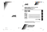
DATAGATE
The bridge to new technologies
User Manual
www.enttec.com
Firmware V2.2
25-Nov-2007
This page Blank
Table of Contents
Contents................................................................................................................4
Contacting ENTTEC............................................................................................ 4
Warranty............................................................................................................... 5
Glossary................................................................................................................ 6
Introduction.......................................................................................................... 7
Features.................................................................................................................7
Basic Concepts..................................................................................................... 8
Connector pin out................................................................................................. 9
DMX OUT:............................................................................................ 9
DMX IN :............................................................................................... 9
RS232:....................................................................................................9
The Menus.......................................................................................................... 10
Menu Structure................................................................................................... 10
Getting Started ...................................................................................................12
DMX Ports:.......................................................................................... 12
Ethernet Channels:............................................................................... 12
Routing Rules:......................................................................................12
Comms Status.....................................................................................................12
NMU configuration............................................................................................ 13
1-Activate Profile............................................................................................... 20
Factory Profiles..............................................................................................20
2-Edit Profile...................................................................................................... 21
2-1-Routing rule.............................................................................................21
Copy .................................................................................................... 22
Merge HTP........................................................................................... 23
Merge LTP........................................................................................... 23
2-2-Port Config.............................................................................................. 23
2-3 Ethernet Config....................................................................................... 25
3-Erase Profile.................................................................................................... 26
4-Erase All Profiles............................................................................................ 26
5-IP Setup........................................................................................................... 26
5-1-IP Address............................................................................................... 26
Datagate User Manual
2
5-2-Netmask.................................................................................................. 26
5-3-Gateway IP.............................................................................................. 26
6-Reset Unit........................................................................................................26
7-Capability........................................................................................................ 26
Web configuration.............................................................................................. 27
Status Page.....................................................................................................28
Routing Engine.............................................................................................. 30
Saving your settings.......................................................................................31
Monitoring..........................................................................................................31
Updating the Application firmware....................................................................32
Appendix 1......................................................................................................... 35
Appendix 2......................................................................................................... 36
Datagate User Manual
3
Contents
When you open the packaging, you should find these items in the box:
•
•
•
•
•
•
•
Datagate (pn:70024)
2 x mounting brackets (pn:79105)
Cross-over Ethernet lead (pn:79101)
Straight connect Ethernet lead (pn:79102)
IEC power cord (Australia only)
User manual
CD (pn:79106)
If one of these items is missing please contact your local dealer.
Contacting ENTTEC
To contact us, please send an email to: [email protected]
Tel: +61 3 9819 2433 GMT+10
Fax: +61 3 9819 2733
To write us:
ENTTEC Pty Ltd
PO BOX 282
KEW, VIC, 3101
AUSTRALIA
Datagate User Manual
4
Warranty
ENTTEC warrants that the product it manufactures and sells will be free from
defects in materials and workmanship for a period of 1 year from the date of
shipment from an authorized ENTTEC wholesaler. If the device proves
defective within the respective period, ENTTEC will repair or replace the
defective hardware at its sole discretion. If the failure is due to an operator error
the user accepts to pay for any charge relating to the diagnosis of the hardware,
faulty parts or shipping from our factory.
ENTTEC makes no warranty of any kind, express or implied, including
without limitation the implied warranties of merchantability and fitness
for a particular purpose. In no event shall ENTTEC be liable for indirect,
special or consequential damages.
Opening the unit voids the warranty as described above.
As this product uses ethernet as a communication medium, we cannot
officially support applications where the Datagate is used on an existing
computer network. We recommend you have a good knowledge of
networking infrastructure and IP networking.
Datagate User Manual
5
Glossary
ACN:
Advanced Control Network.
Art-Net:
Artistic License network protocol. This is the Artistic License
DMX over ethernet protocol.
Channel:
On the front panel of the Datagate, the term Channel is
used synonymously with a DMX over Ethernet Stream or
Universe. It may at other times mean a single DMX address or
slot within a Stream or Universe.
Dimmer:
One discretely controlled device or parameter of a device out of
512 possible in the DMX512 protocol. Also referred to as
“Address”, and in confusingly inopportune moments, “DMX
Channel” or “Output Channel”
DHCP:
Dynamic Host Configuration Protocol.
ESP:
Enttec Show Protocol. This is the Enttec DMX over ethernet
protocol.
HTP:
Highest Takes Precedence.
IP:
Internet Protocol.
LCD:
Liquid Crystal Display.
LTP:
Lowest Takes Precedence.
PC:
Personal Computer.
Stream:
A DMX512 over Ethernet Universe coming into or leaveing the
Datagate
Universe:
512 addresses or slots worth of control information as conveyed
by DMX512 protocol. As a lighting system may have more than
512 discrete things to control, multiple universes may be
required. When this is the case, the Universe number will be
expressed in 0-255 form for ESP or 0-15 subnet and 0-15
universe # for Art-Net.
Datagate User Manual
6
Introduction
Thank you for buying the Datagate. At ENTTEC we are proud of our products
and we hope you will enjoy them as much as we enjoy making them.
Firstly, unpack the unit from the box. The Datagate occupies a single unit (1U)
in a 19 inch rack.
On the front panel, you will find :
• RJ45 Ethercon connector for a 10Base-T Ethernet connection
• LCD screen
• 3 buttons (MENU, SCROLL, ENTER)
• 8 DMX output connectors
• 1 DMX input connector
On the back of the rack you will find:
• IEC connector, you can insert any AC voltage source between 100 and 260 V
and 50 to 60Hz
• RS232 port
The unit has no power switch and can be left on continuously.
Datagate User Manual
7
Features
•
•
•
•
•
•
•
•
•
•
8 1500V opto isolated DMX ports
Break time configurable for each DMX port (88us to 1ms)
DMX refresh rate configurable for each port (1Hz -> 44Hz)
Number of channels configurable for each port (1 to 512)
Profile editing and setup done through Node Management Utility, or inbuilt
front panel menus, or inbuilt web page
Data throughput Statistics available through web page
Supports ESP and Art-Net protocols for DMX over Ethernet
ACN ready
Routing Engine supports Copy, Merge HTP and Merge LTP
LCD display provide status information on port direction and data flow
Limitations:
As the Datagate is reliant on Ethernet, if you are using an existing computer
network and sharing the traffic between your lighting control system and other
functions, or if you are using multiple datagates, you might experience delays
and a drop in the update rate.
Datagate User Manual
8
Basic Concepts
The Datagate is :
•
DMX Hub/Splitter
•
DMX Merger (HTP or LTP)
•
DMX -> Ethernet
•
Ethernet -> DMX
•
Or any combination of the above
Changing from one mode to another is as easy as pressing 2 buttons.
Datagate User Manual
9
Connector pin out
DMX OUT:
Pin 1: Ground
Pin 2: Data Pin 3: Data +
Pin 4: NC
Pin 5: NC
DMX IN :
Pin 1: Ground
Pin 2: Data Pin 3: Data +
Pin 4: NC
Pin 5: NC
Datagate User Manual
10
The Menus
To access the menus the Datagate offers 3 buttons on the front panel:
MENU, SCROLL, ENTER.
MENU is used to cancel the current action or go up one level in the menus
SCROLL is used to scroll through the menus or scroll through values
ENTER is used to validate the current setting, or enter the selected menu.
Menu Structure
Comms Status
1-Activate Profile
2-Edit Profile
2-1-Routing rule
2-1-1-Input A
2-1-2-Input B
2-1-3-Output
2-1-4-Type
2-1-5-Start Address B
2-1-6 Start Address C
2-1-7 Merge/Copy Length
2-2-Port Config
2-2-1-Port Type
2-2-2-Number of channels
2-2-3-Break Length
2-2-4-Refresh Rate
Datagate User Manual
11
2-3 Ethernet Config
2-3-1-Protocol
2-3-2-Universe
2-3-3-Send as
2-4 Profile Name
3-Erase Profile
4-Erase All Profiles
5-IP Setup
5-1-IP Address
5-2-Netmask
5-3-Gateway IP
6-Reset Unit
7-Capability
Datagate User Manual
12
Getting Started
When you power up the Datagate for the first time, the default factory profiles
will occupy profiles 1 to 3 depending on the capability purchased:
Datagate D:
only DMX hub profile will be created
Datagate DM:
only DMX hub profile will be created
Datagate DME:
will be created
DMX hub, Ethernet->DMX, DMX->Ethernet profiles
Each Profile contains configuration information for:
DMX Ports:
These are the physical INPUT or OUTPUT DMX ports 1 to 8.
Ethernet Channels:
These are the DMX over Ethernet universes, also referred to as Streams
in the Node Management Utility.
Routing Rules:
Rules decide how frames are moved or routed inside the routing engine,
they also decide if data is merged.
Comms Status
When no key is pressed for a while, the Datagate will show the Communication
Status of the Ports and Channels. An example display is shown below:
Port:
1-3-5-7Channel: -2-4-6-8
where
“-” indicates port or channel is unused.
Datagate User Manual
13
Normal video text for the numerals “1” to “8” indicate port numbers or channel
numbers that are configured as outputs, and the number blinks when
transmitting.
Inverse video text for the same numerals indicate port numbers or channel
numbers that are configured as inputs, and the number blinks when receiving.
NMU configuration
NMU (Node Management Utility) is the free Windows and OSX application
used to manage compatible ENTTEC DMX over Ethernet nodes.
NMU bypasses all your TCP/IP settings allowing you to reconfigure nodes in a
plug and play fashion, how ever they are configured.
NMU Currently supports profile editing on the Datagate with V2.0 or above
firmware. With firmware 2.2 and higher, the NMU will allow you to select the
active profile as well.
The NMU is by far the easiest of the three methods available to configure your
Datagate. The other methods are suitable for special cases, still, such as times
when you want to change a configuration but no computer is available (menu
buttons), or if you are interested in monitoring only (web).
To employ the NMU, follow this set of instructions:
1. If you have not already done so, download and install the application
from the Enttec website www.enttec.com
2. Ensure that your Datagate is hooked up physically by Ethernet cable to
the same physical network as the computer on which you will run the
NMU.
3. Start the application.
4.
Datagate User Manual
14
5. Press the Discovery button.
6.
Datagate User Manual
15
7. Select a Datagate.
8. The configure button will now be enabled; press it to continue.
9. Make changes to the general settings, if desired.
Datagate User Manual
16
10. Select the Profile Settings tab if you wish to make changes to one or
more of the profiles.
11. Editing Profiles: The Profile Editing screen is fairly self-explanatory.
You need to select which profile you want to change from the list at the
top, and then adjust the parameters displayed to suit your needs. The
picture below shows a blank profile that has not been customized yet.
Datagate User Manual
17
Datagate User Manual
18
12. Note that there are 8 ports,
with the selectable options
of Disabled, Output DMX or
Input DMX
13. Under Ethernet Streams you
will see 8 more rows with a
protocol and a Universe number
selectable for each. Protocols
supported are ESP and Art-Net.
Datagate User Manual
19
14. There are 8 rules to configure for each profile. These will take the form
of specifying one input for copy operations or two for merging, the
operand, and the output, as well as some details of the configuration for
each universe specified. The illustration above shows the choice of Op
Type, with None, Copy, Merge Highest Takes Precedence and Merge
Last Takes Precedence available as choices.
The next illustration shows an example rule fully formed. It would be a
merge between two input ports, with the signal that results being sent
out to whatever DMX universe Stream1 is defined as. The nature of LTP
merging is that the entire row's output will be Input A or B, not a
mixture of the two. Highest Takes Precedence may be a mixture,
depending on channel values moment by moment, but LTP is a gate that
swings for an entire rule, one way or the other.
Datagate User Manual
20
A bit more detail about these rules, and defining the input and output
ports and streams can be found in the section related to menu-based
profile editing below (menu items 2.0 through 2.3.3).
15. Profiles can be saved to and loaded from hard disk as well as
downloaded to the Datagate. Once you have completed making and
saving your changes, Close the NMU Datagate configuration window,
and then exit the NMU application (or pick another Datagate to
configure.)
Menu Based Operation
The following section offers documentation about the use of the menus to
change things that are also available in the NMU. Because the unit may be
separated from a computer this is valuable to learn, but it will be significantly
faster to use the NMU in most cases, so that is the recommended practice where
feasible. (For menu item 1, the Activate Profile, either method is about the same
in terms of speed, but the differences increase steadily after that.)
1-Activate Profile
This menu is used to activate the selected profile, press ENTER to edit and then
SCROLL to select the desired profile. Then press ENTER to activate it. The
Datagate will display:
“Profile Activate”
The Datagate will reconfigure itself to the profile you have just selected.
Factory Profiles
The Datagate has a set for factory profiles, these are:
•
DMX Hub: This profile inputs DMX on port 8 and the signal is replicated
onto ports 1 to 7
•
4 Way Isolator: This profiles is used to isolate 4 DMX streams, signal on
input 1 is replicated to port 2, signal on port 3 is replicated on port 4 ... You
will need gender changers with this profile.
Datagate User Manual
21
•
7 to 1 HTP Merger: This profile does an HTP merge of inputs 1 to 7 and
send the result onto port 8
•
DMX -> Ethernet: This profile takes 8 DMX signals on ports 1 to 8 and send
them over Ethernet using ESP protocol. This profile can be used to create an
8 way wireless DMX link.
•
Ethernet -> DMX: This profile will take 8 DMX over Ethernet signal using
the ESP protocol and convert them to 8 DM<X signal on ports 1 to 8. This
profile can be used as the corresponding end of the profile above (DMX ->
Ethernet)
•
Art-Net: This profile simulates a standard Art-Net node, with 4 DMX input
and 4 DMX outputs, all ports linked with 8 Art-Net universes. Use this
profile as a drop in replacement for a standard Art-Net box
These profiles are just an example of what can be done with the Datagate, you
can modify the factory profiles to accommodate your particular need, or create
your own profile from scratch.
2-Edit Profile
This menu is used to edit a particular profile. Press ENTER to edit and then
SCROLL to select the profile you wish to edit, then press ENTER.
2-1-Routing rule
Select the routing rule you wish to edit. The routing engine has 8 rules that
determine what happens to the dmx data, rules are built as the following:
A op B -> C
A,B or C can be any DMX port or Channel
Datagate User Manual
22
A is the reference
B is the source
C is the destination
op (Operator) can be: Copy, Merge LTP, Merge HTP
For example a straight rule for a Ethernet (Art-Net universe 0-0) to DMX port 1
for all 512 channels would be.
A= Ethernet Channel 1 set to Art-Net 0-0
B= (empty)
op = COPY start address 1, length 512
C=DMX Port 1
2-1-1-Input A
This menu selects the reference DMX port or Channel
2-1-2-Input B
This menu selects the source DMX port or Channel. B must be defined for LTP
Merging or HTP merging.
2-1-3-Output
This menu selects the output DMX port or Channel
2-1-4-Type
This menu selects the type of operator used in the rule, options are:
Copy
If B is NONE:
C is cleared, then “length” bytes of A are copied to C starting at “Start Address
C”
Datagate User Manual
23
if B is a Port or Channel:
A is copied into C, then “length” bytes of B starting at “Start Address B” are
copied to C starting at “Start Address C”
Merge HTP
A is copied into C, then “length” bytes of B starting at “Start Address B” is
HTP merged with C starting at “Start Address C”
Merge LTP
A is copied into C, then “length” bytes of B starting at “Start Address B” is LTP
merged with C starting at “Start Address C”
2-1-5-Start Address B
See 2-1-4
2-1-6 Start Address C
See 2-1-4
2-1-7 Merge/Copy Length
See 2-1-4
2-2-Port Config
This menu configures the DMX ports.
2-2-1-Port Type
Options:
DMX Disabled
DMX Input
DMX Output
Datagate User Manual
24
2-2-2-Number of channels
This sets the number of channels of DMX data that are output on that DMX
port.
2-2-3-Break Length
This sets the DMX signal break length for that particular port.
2-2-4-Refresh Rate
This sets the DMX signal refresh rate for that particular port. By default the
Datagate will emit the maximum rate of 44 frames per second. Some equipment
does not support such high frames rates, and this setting can be used to reduce
the refresh rate.
Datagate User Manual
25
2-3 Ethernet Config
This menu configures the DMX over Ethernet channels. The Datagate supports
8 channels.
2-3-1-Protocol
This menus configures the DMX over Ethernet protocol used, possible options
are ENTTEC protocol (ESP) or Art-Net.
Please note: the Art-Net protocol has a limited implementation due to the fact
that Art-Net does not support devices with more than 4 DMX ports.
2-3-2-Universe
This menu configures the universe assigned to that particular channel.
2-3-3-Send as
When the channel is used as an output (sending DMX), packets can be sent
using different broadcast classes.
Possible options are:
Full broadcast:
packets will be sent to 255.255.255.255
Class A broadcast:
packets will be sent to IP.255.255.255
Class B broadcast:
packets will be sent to IP.IP.255.255
Class C broadcast:
packets will be sent to IP.IP.IP.255
Datagate User Manual
26
3-Erase Profile
This menu erases a particular profile. Any profile can be erased with this
command, whether or not the profile is a default factory profile.
4-Erase All Profiles
This will erase all profiles, and recreates the default factory profiles.
5-IP Setup
This menu is used to configure the IP stack inside the Datagate. IP configuration
can be automatic through DHCP or static.
5-1-IP Address
Use this menu to set a static IP for the Datagate.
5-2-Netmask
Use this menu to set a static net mask for the Datagate.
5-3-Gateway IP
Use this menu to set a static gateway IP address. For no gateway, set this to
A.B.C.254, where the IP address is A.B.C.D.
6-Reset Unit
Use this menu to reset the Datagate processor, as though the unit had been
powered off then on. This avoids having to turn power off or unplug the mains
lead which might be inaccessible.
7-Capability
When upgrading functionality eg: from a Datagate D to Datagate DME, you
will be provided with a new capability code. Enter this capability code here to
upgrade your Datagate.
The capability code will only work on that particular device.
Datagate User Manual
27
Web configuration
To configure the Datagate, you can use any web browser such as Internet
Explorer or Netscape.
Type in the address of the Datagate in the address bar like this:
http://10.5.2.6 where 10.5.2.6 is the IP address of the Datagate, for example.
When using DHCP, the logs of the DHCP server can tell you the IP assigned to
the Datagate using the serial number / MAC address as reference.
Once the address has been entered into your favorite web browser, the main
page will appear:
Datagate User Manual
28
Status Page
The main page is the status page; it displays general information about the
Datagate User Manual
29
Datagate.
Node Name: The node name is displayed when using protocols such as Art-Net.
DHCP Enable: Ticking this box will enable DHCP configuration of the IP
address. You must have a DHCP server running on your network for this to
work. If not, the Datagate will wait for 60 seconds for a response then use the
pre-configured IP address. During the DHCP timeout no DMX is sent or
received.
IP: This is the IP address that is used if DHCP is disabled.
Netmask: This is the Netmask that is used if DHCP is disabled.
Gateway: This is the Gateway that is used if DHCP is disabled.
Datagate User Manual
30
Routing Engine
The routing Engine screen is used to view the status of the routing engine and
select a different profile.
Datagate User Manual
31
To activate a different rule, simply select it by clicking on the corresponding
checkbox and click on Change. The profile is immediately activated. No need
to save the setting to take effect.
Saving your settings
When you make a change to any setting (aspart from the active profile), make
sure you click on the update setting button on the bottom of the page. The
change will take effect immediately but is not saved in non volatile memory.
To save the changes permanently click on the SAVE link in the menu.
Monitoring
GateConfig available from our website can be used as a monitoring tool. By
clicking on the DMX menu, you can monitor the values of all DMX channels
for every universe being sent over the Ethernet.
You can also use this as a debugging tool. You can monitor the nodes on your
network and also check the amount of traffic being generated.
Datagate User Manual
32
Updating the Application firmware
To update the firmware on the Datagate, you will need a DHCP and TFTP
server. It is best to set aside a computer connected directly using a cross over
patch lead to the Datagate.
Fortunately there is a windows program that includes a DHCP and TFTP server
in one: TFTPD32 available at : http://tftpd32.jounin.net/
Create a folder in your C drive called temp, and place the new Datagate
firmware file (datagate.bin) in that folder.
You will need to configure this program, please configure using the screen shots
below as reference.
When you start the software the screen will look like this:
Datagate User Manual
33
Click on DHCP server tab and configure like the screen below:
The “Boot file” is the new firmware you wish to load.
Datagate User Manual
34
Click on the setting tab and configure like the screen below:
Once TFTPD32 is configured correctly, put the Datagate in System mode by
pressing the ENTER key when you power up the Datagate. Keep the enter key
presssed until the firmware starts loading.
The update will only take 2 to 3 seconds. Please wait until the download
progress bar on TFTPD32 is closed.
To put the Datagate back into normal mode simply cycle the power.
The update is completed.
Datagate User Manual
35
Appendix 1
Federal Communications Commission (FCC) Declaration of Conformity
Responsible Party:
ENTTEC Pty/Ltd
Level 1, 672 Glenferrie Rd,
Hawthorn,Vic,3122
Australia
declares that the products:
Product Name: Datagate
complies with Part 15 of the FCC Rules. Operation is subject to
the following two conditions: (1) This device may not cause
harmful interference, and (2) this device must accept any
interference received, including interference that may cause
undesired operation.
This equipment has been tested and found to comply with the
limits for a Class B digital device, pursuant to Part 15 of the
FCC rules. These limits are designed to provide reasonable
protection
against
harmful
interference
in
a
residential
installation.
This equipment generates, uses and can radiate
radio frequency energy and, if not installed and used in
accordance with the instructions, may cause harmful interference
to radio communications.
However, there is no guarantee that
interference will not occur in a particular installation.
If
this equipment does cause harmful interference to radio or
television reception, which can be determined by turning the
equipment off and on, the user is encouraged to try to correct
the interference by one or more of the following measures:
- Reorient or relocate the receiving antenna.
- Increase the separation between the equipment and the
receiver.
- Connect the equipment into an outlet on a circuit
different from that to which the receiver is connected.
Consult
the
dealer
technician for help.
or
an
experienced
radio/TV
*
In order to maintain compliance with FCC regulations
shielded cables must be used with this equipment. Operation with
non-approved equipment or unshielded cables is likely to result
in interference to radio & television reception.
Datagate User Manual
36
Appendix 2
We
ENTTEC Pty Ltd
Level 1, 672 Glenferrie Rd,
Hawthorn, Vic, 3122
Australia
declare under our sole responsibility that our products:
Datagate
conforms to the requirements of Council Directives 89/336/EEC and 73/23/EEC and therefore complies with the
requirements of Council Directive 73/23/EEC, (The Low Voltage Directive) on the harmonization of the laws of
Member States relating to electrical equipment designed for use within certain voltage limits as amended by Article 13
of Council Directive 93/68/EEC
•
•
•
EN 55103-1
EN 50103-2
EN 60065/AS 3650
Datagate User Manual
37