1
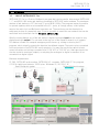
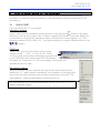
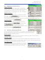
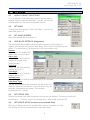
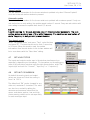
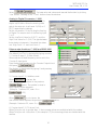
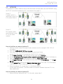
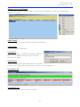
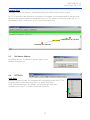
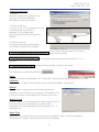
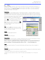
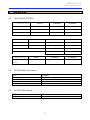
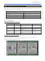
SATELLINK PC Pro
User Guide, EN, V 2.0
USER MANUAL
SATELLINK PC Pro
Routing program
for
Point-to-Multipoint Operation
1
SATELLINK PC Pro
User Guide, EN, V 2.0
TABLE OF CONTENTS
TABLE OF CONTENTS...........................................................................................................2
1
GENERAL ........................................................................................................................4
1.1 ABOUT SATELLINK PC PRO .....................................................................................4
2
INITIAL SETTINGS ...........................................................................................................5
2.1 SATELLINE RADIO MODEM AND SATELLINK-SERIES CONFIGURATIONS ..............5
3
HOW TO START USING OF THE PROGRAM ....................................................................6
3.1 QUICK START .........................................................................................................6
3.2 SENDING TO SUB-STATIONS.................................................................................7
3.3 RECEIVING FROM SUB-STATIONS .........................................................................7
4
EDIT MODES ...................................................................................................................8
4.1 HOW TO SELECT FUNCTIONS ...............................................................................8
4.2 SET NAME ..............................................................................................................8
4.3 SET SLAVE ADDRESS ..............................................................................................8
4.4 SAFE MODE SETTINGS (DIAGNOSTICS) .....................................................................8
4.5 SET UPDATE TIME...................................................................................................8
4.6 SET UPDATE MODE (CONCERNS ONLY RECEIVED DATA)................................................8
4.7 SET LAYOUT STYLE.................................................................................................9
4.8 SET UNIT CONVERSION ........................................................................................9
4.9 CONNECTION TYPE.............................................................................................11
4.10 SHOW SLAVE VERSION ....................................................................................11
4.11 LOAD SETTINGS................................................................................................11
4.12 SAVE SETTINGS.................................................................................................11
4.13 CLOSE (CLOSE THE SUB-STATION) ..........................................................................11
4.14 EXIT...................................................................................................................11
4.15 SAVE ALL SLAVES..............................................................................................11
4.16 LOAD ALL SLAVES.............................................................................................11
4.17 EDIT ..................................................................................................................11
5
FILE-MENU ...................................................................................................................12
5.1
5.2
5.3
5.4
5.5
5.6
5.7
6
MASTER CONFIG-MENU...............................................................................................13
6.1
6.2
6.3
6.4
7
NEW SLAVE..........................................................................................................12
LOAD SLAVE(S).....................................................................................................12
SAVE ALL SLAVES .................................................................................................12
CLOSE ALL SLAVES...............................................................................................12
LOAD WORKSPACE..............................................................................................12
SAVE WORKSPACE...............................................................................................12
EXIT......................................................................................................................12
COM-PORTS 1…8 ................................................................................................13
NETWORK ............................................................................................................14
SET MASTER ADDRESS ..............................................................................................16
SETTINGS .............................................................................................................16
WINDOW-MENU ..........................................................................................................20
7.1 SHOW ACTION LOG .................................................................................................20
7.2 SHOW ROUTE LIST ...................................................................................................20
7.3 SHOW CHANNEL SELECTOR .......................................................................................20
2
SATELLINK PC Pro
User Guide, EN, V 2.0
7.4 SHOW MAP VIEW ....................................................................................................23
7.5 SHOW ACTION LIST .................................................................................................24
8
ROUTING......................................................................................................................29
8.1 START...................................................................................................................30
9
INDICATORS.................................................................................................................31
9.1 ADJUSTABLE SETTINGS........................................................................................31
9.2 BOTTOM BAR, SUB-STATION ..................................................................................31
9.3 BOTTOM BAR, MASTER ..........................................................................................31
10
FACTORY SETTINGS AND ACCESSORIES ....................................................................32
10.1 ACCESSORIES ...................................................................................................32
11
CONNECTION EXAMPLES...........................................................................................33
3
SATELLINK PC Pro
User Guide, EN, V 2.0
1
1.1
GE NERAL
ABOUT SATELLINK PC Pro
SATELLINK PC Pro is a Point-to-Multipoint program that can be used to drive several SATELLINK
I-, C- and MINI-LINK series sub-stations connected to SATELLINE radio modems. The maximum
number of sub-stations is 127 (but only 15 pcs of MINI-LINKs). The program makes it possible
to operate systems, which are connected to the I/O -ports, to change values, collect pulses,
monitor the radio link and Multipoint operation etc. The monitoring can be diverted to a
wallpaper picture, for example a map. It is also possible to create an own network that can be
monitored and controlled over the E thernet (WAN/LAN).
With the routing feature any of the sub-station’s digital/analogue input can be routed to any
digital/analogue output. You can even route any one of the inputs to several or all outputs.
This feature is useful for example emergency multi-alarm e.g. routing is done by the PCprogram, which virtually connects the Inputs to the defined outputs. The input can be connected
to the any output of the SATELLINK-series products. You may thus use this as switch isolator,
current converter and voltage converter from 12-24 VDC to 230 VAC etc. Analogue inputs can
also be routed to analogue outputs, or adopting the analogue to digital conversion to be
converted to a digital signal.
Minimum requirements:
PC 286, SATELLINE radio modem, SATELLINK I/O-converter, SATELLINK PC Pro program,
COM Port with baud rate min. 9600 b/sec. Windows 95, 98, 2000, XP.
Small Multipoint system
Routed Multipoint system
4
SATELLINK PC Pro
User Guide, EN, V 2.0
2
2.1
INITIAL SETTINGS
SATELLINE RADIO MODEM AND SATELLINK-SERIES CONFIGURATIONS
Baud Rate
Set the baud rate of the SATELLINE radio modem. Check that the other parameters are “N-8-1”.
Set the baud rate of the SATELLINK device by using the BAUD DIP -switches.
00=2.4, 10=4.8, 01=9.6, 11=19.2kbs
The baud rate of the MINI-LINK is fixed 9.6kbs
Check that the SATELLINE radio modems have the same settings.
Protocol
Set the PRTCL switch of the SATELLINK device to the Multipoint position, P-to-MP or M.
Address
Set personal addresses to all SATELLINK device sub-stations by using the ADDRESS DIPswitches.
Connections
Before connecting the device to a power supply, first connect all inputs and outputs. There is
more information about connections at the end of the manual.
5
SATELLINK PC Pro
User Guide, EN, V 2.0
3
HOW TO START USING OF THE PROGRAM
In this section "HOW TO START USING OF THE PROGRAM, is described all necessary
information to make the system operational. Other tunings and settings are described in the
next sections.
3.1
QUICK START
Open the SATELLINK PC Pro program.
Operation Window
Open a new operation window(s) from the toolbar list by clicking the
-button on the upper
left corner, or Open by clicking on the File Menu, opening "New Slave". Open own window for
all Sub-stations. Note, that the maximum number of Sub-stations in this program is 127 (the
maximum number of MINI-LINKs is 15). Arrange the display by using the Windows Menu or the
-buttons.
COM-Port
Open COM- port from the toolbar list by clicking
“Master Config” – “Port1…8” and “Open”. Select
COM-port and set the same parameters as you have set
for the SATELLINE radio modem and SATELLINK device,
and press OK. If there are no COM -port settings, the program will
automatically ask for them.
Sub-station address
When the new sub-station is opened, the program will automatically set the
address for it. To make manual adjustments, click anywhere on the empty grey
area of the sub-station window using the right mouse button, and select “Set
Slave address”. Insert the new address, and then press OK.
The basic settings have now been established and the SATELLINK PC Pro is
ready to send and receive.
6
SATELLINK PC Pro
User Guide, EN, V 2.0
3.2
SENDING TO SUB-STATIONS
Digital information
To change the sub-station's digital value, click the gray
“Digital Output” circle dot. During the transmission the dot
is yellow. When the transmission is done, the circle will
change to green. If the transmission fails, the “Operation”
signal will turn red.
Analog information
Move the “Analog Output Cursor” or change the number
at the side. Press
and the levels will be
sent to the Sub-station's “Analog Output”.
If the transmission fails, the “Operation” signal will turn red. Note that “Analog Output” can
only be sent by pressing
.
Pulse information
In order to send the pulses to the sub-station, write the
number of pulses to the
block and press
. If the transmission fails, the
“Operation” signal will turn red. Note that the pulses can be
sent only by pressing
.
3.3
RECEIVING FROM SUB-STATIONS
To make updates from the sub-stations, click anywhere on the empty grey area of
the sub-station window using the right mouse button, and select the one of the
following: Manual, Automatic or Time.
Manual update
The sub-station information for the chosen window is updated only when “Manual Update”
circle-dot in the sub-station window is pressed.
Automatic update
The sub-station information for the chosen window is updated with maximum speed. If only one
sub-station has an auto setting, the update speed is about 1 second. Every new sub-station with
auto setting increases the update time about 1 second.
Time based update
The update information from the sub-station to the chosen
window will be in accordance with the “Select time” setting.
The time interval can be from 1 second up to 24 hours.
7
SATELLINK PC Pro
User Guide, EN, V 2.0
4
4.1
EDIT MODES
HOW TO SELECT FUNCTIONS
Click anywhere on the empty grey area of the sub-station
window using the right mouse button. This will open a new
window where you can select the desired function.
4.2
SET NAME
Changes the default name. Select "Set Name" – type a new
name and press OK.
4.3
SET SLAVE ADDRESS
Insert the new address and press OK.
4.4
SAFE MODE SETTINGS (diagnostics)
The Safe Mode Setting defines what should be done to the sub-station’s
outputs, if the master in the pre-set Safe Mode Time has not contacted the substation. This function acts like diagnostics to the sub-station units.
Normal
No changes - the outputs will
remain their current position.
Alarm only
Alarm LED will be lit and the
outputs will remain their
current position.
Ports Low
Alarm LED will be lit and the
outputs will go OFF.
Ports High
Alarm LED will be lit and the
outputs will go ON.
Defined Ports
Alarm LED will be lit and the outputs will go to pre-set state.
Safe Mode Time
The pre-set time defines the time when the sub-station will
make the above pre-set actions, if the sub-station has not
got been contacted by the master. The minimum
increment time is 1 minute.
4.5
SET UPDATE TIME
Defines the interval how often the master contacts the sub-stations. The time can be from 1
second up to …24 hours. Select "Set Update Time”, set the time and press SET.
4.6
SET UPDATE MODE (concerns only received data)
There are 3 different modes to receive Data; Manual, Automatic or Time.
The settings can be done separately for each sub-station.
8
SATELLINK PC Pro
User Guide, EN, V 2.0
Manual update
The sub-station information for the chosen window is updated only when “Manual Update”
circle-dot in the sub-station window is pressed.
Automatic update
The sub-station information for the chosen window is updated with maximum speed. If only one
sub-station has an auto setting, the update speed is about 1 second. Every new sub-station with
auto setting increases the update time about 0,5 second.
NO TE!
Use thi s setting for the sub-stations only, if it is abso lutely necessar y. The auto
setting makes maximal use of the radio frequency. The continuous re se rvation of
radio frequency is not generally recommended.
Time based update
Select “Set update mode” and press “Time”, select the time
and press SET. The time interval can be from 1 second up
to 24 hours. When this mode is used, the update
information from the sub-station to the chosen window will
be in accordance with the “Select time” setting.
4.7
SET LAYOUT STYLE
The inputs and outputs can be seen in the window simultaneously or
separately, depending on the settings. Click anywhere on the empty grey
area of the sub-station window using the right mouse button, select "Set
layout style" and set it for “Normal”, “Input only” or “Output only”.
4.8
SET UNIT CONVERSION
As default the analog input and output
values are shown as % and the scaling is
from 0 to 100 %.
The default unit “%” can be changed to any
other unit, maximum 5 characters. The value
can also be re-scaled by setting the
minimum and maximum values that the
sensor and device applies. Low and high
alarm warning values can be set separately
for each analogue input.
9
SATELLINK PC Pro
User Guide, EN, V 2.0
Select
. Set new units and values and execute the function by clicking
“Use” button. Pressing of the “Close” button closes the window.
Analog to Digital Conversion, I-LINK
An analogue input level can be converted to
digital on/off state. When the analog value
gets to the set point, it will send 1 (ON) or 0
(OFF) regarding the settings.
Set the conversion ON by clicking the Analog
to Digital Conversion box of the Analog Input
1 or 2.
Set the Low Point Value for 0 (OFF), and the
High Point Value for 1 (ON). The gap between
these states is hysteresis. If inverted, the states
are: High Point = 0 and Low Point=1.
Pulse counter functions, C-LINK and MINI-LINK
1. Counter Output and Input 1, 2/ Unit.
The default Unit "Tick" is replaced by typing new text.
2. Counter Output 1, 2/ Auto Mode:
When selected a fixed frequency can be set to the
Counter Output ports.
Type the desired frequency to the Counter Output block
Auto Mode
.
and press
The function is deactivated by typing 0 and pressing
.
3. Counter Input 1,2 / Additive count:
When
is chosen, the
new counter value is added to the previous
value. The update is done in
every request by the program.
(Example: Previous=20, new=3=>
=23)
Additive count
When
is not chosen, the
new counter value replaces the previous
(Example: Previous=20, new=3=>
value.
=3).
4. Counter Input 1,2 / Ticks per Unit:
When Ticks per unit is greater than 1, the incoming pulses are multiplied with this number.
When Ticks per unit is less than 1 (for example 0,1), the incoming pulses are divided with this
number.
10
SATELLINK PC Pro
User Guide, EN, V 2.0
4.9
CONNECTION TYPE
Current sub-station can be changed to use any other possible Port 1...8 in
the system.
4.10 SHOW SLAVE VERSION
This function will show the software version of the LINK device.
4.11 LOAD SETTINGS
Opens saved settings from the file. Select "Load Settings" browse for the file
and press OK.
4.12 SAVE SETTINGS
Saves the current Sub-station to the PC. Select "Save Settings", browse for the file and press OK.
4.13 CLOSE (close the sub-station)
This will close only the individual sub-station, not the whole
program. In the event that the sub-station has not be saved, the
program asks “Are you sure you want to close slave? Select Yes
/No." However, it is recommended to either save the individual
sub-station or the whole workspace (File- Save Workspace…)
4.14 EXIT
Select FILE – EXIT. If any of the sub-stations are still open, the program asks
“Are you sure?” Select Yes /No.
4.15 SAVE ALL SLAVES
Select FILE - "Save All", select path and save. This function will save all sub-stations using their
current names.
4.16 LOAD ALL SLAVES
Select FILE - "Load Slave(s)" and open the file. Because the information of
the now loaded sub-station may be different from what it currently is, the
program asks, “Do you want to update slave(s)? Select Yes / No".
4.17 EDIT
Changing of the Input / Output names
Click normally at the name that you want to change and it
opens for editing. Make the changes and press ok.
11
SATELLINK PC Pro
User Guide, EN, V 2.0
5
5.1
FILE-m enu
NEW SLAVE
Opens a new sub-station on the main window.
5.2
LOAD SLAVE(s)
Loads a saved sub-station from the file.
5.3
SAVE ALL SLAVES
Saves all sub-stations to the file.
5.4
CLOSE ALL SLAVES
Closes all sub-stations from the window.
5.5
LOAD WORKSPACE
Loads the whole workspace from the file. When the saved workspace is loaded from the file, the
program will not automatically start its operation, even though the saved workspace had auto
boot and auto time setting. For security reasons the program will start on manual mode.
PC Pro Program will start automatically only, if the auto boot has been activated and the PC
has gone through an abnormal shut down i.e. power failure etc.
5.6
SAVE WORKSPACE
Loads the whole workspace to the file. Recommended feature. When done the all settings, such
as names, routings, times etc., will be saved.
5.7
EXIT
Closes the I-LINK PC Pro program.
12
SATELLINK PC Pro
User Guide, EN, V 2.0
6
MASTER CONFIG-m e nu
In this part are explained most of the settings that have an effect on
the program functions.
6.1
COM-PORTS 1…8
In case you have different frequencies or you want to connect
SATELLINK -products directly to your PC, you can use eight (8)
different COM ports. The usage of multiple COM ports makes it
possible to build up several systems and different combinations for
one PC-Pro program.
Open new Com-Port
On the top bar, click the “Master Config”. Open the port that you
want to use. Both ports can be used for similar operation. Note that you cannot use two COM
ports to drive same sub-station.
How to use Com-Ports
Open new sub-station. Click anywhere on the empty table of the
selected sub-station by using the right mouse button, click on
"Connection Type” and select new port.
New COM port can be connected directly to I-LINK or C-LINK 100
(even without modem), with a special null-modem cable D9f/D15f or
normally with SATELLINE radio modems. If needed the radio modems
can use different frequencies in each COM port.
Routing the LINK device inputs from one COM port to another COM
port is also possible.
13
SATELLINK PC Pro
User Guide, EN, V 2.0
6.2
NETWORK
It is possible to create a network that can be monitored and operated over the ETHERNET using
the TCP/IP connection between the PC’s connected to the network.
Picture 1.
A system, which is
monitored by two PCs
in the same network.
Picture 2.
Two systems, which
are monitored by two
PC’s in the same
network.
How to build up a network (picture 1)
1. Build up a radio network (using the radio modems and for example I-LINK 100 I/Oconverters).
2. Open the S ATELLINK PC Pro program.
3. Open the I-LINK 100 operational window to your Local Server
(on the left of the picture 1) and set the I-LINK 100 I/O-connections.
4. Click M aster C onfig on the standard toolbar and select S ettings
5. Provide A dminist rative Passw o rd for network connections (default: ProNetwork).
6. Type the N etwo rk Po rt that this server is listening. S ave and Clo se
7. Click M aster C onfig on the standard toolbar and select P ro Netwo rk. Click O pen
Server
8. Click C onnect To and type the R emote Addre ss Input. This is the TCP/IPP address
of the remote PC that is networked to this PC. Click O K
9. Make the settings 2-9, except step 3, to the Remote Station
(on the right of the picture 1) and the network connection between these two PCs has
been established.
How to build up a network (picture 2)
1. Make the above settings to the PC on the right, except step 9.
14
SATELLINK PC Pro
User Guide, EN, V 2.0
Settings of the Local Station
Click Master Config on the standard toolbar. Select Pro Network. A new Pro View window
appears as below.
Open Server
Opens the TCP/IP Port for listening inbound connections.
Close server
Closes all server connections.
Connect To
Connect To opens a new window, Remote Address
Input. TCP/IP address of the other PC that the
connection is made.
Ping Servers
When clicked, it shows the server that the connection
is made. If no Ping result is received the connection is not established.
Connection List
Opens a list of the connection parameters.
Connection Log
Shows a list of the action that has occurred.
15
SATELLINK PC Pro
User Guide, EN, V 2.0
Network Map
Automatic view of the network. Shows the network form this server’s point of view.
NOTE! If more than two servers is connected to the system, it is recommended to add the new
servers to the previous server in the system and so on (2nd server is connected to the 1st. 3rd is
connected to the 2nd and so on, so 3rd is not connected to 1st).
6.3
Set Master Address
As default this is 0. If needed to change, type in new
number and press ok.
6.4
SETTINGS
Auto Boot
When this feature is used, the computer will automatically start the PC Pro
Program after an abnormal shut down i.e. power failure etc.
Note, that depending on the settings, the program will also start
automatically, if the PC has been shut down normally.
16
SATELLINK PC Pro
User Guide, EN, V 2.0
Activating Auto Boot
1. Saving
When all names and routings etc. are
done, go to File-menu Save
Workspace, name it and save it.
2. Saving a Shortcut
Copy the I-LINK PC Pro-program shortcut
to Windows Startup-directory
(example C:\Documents and
Settings\XXXX\Start Menu\Programs\
Startup).
3. Settings and start
The program will start automatically
according to the Auto Boot settings.
The program starts automatically after an
abnormal shut down.
The program starts automatically when the PC Pro is
opened.
The opening procedure is shown in the screen.
The settings are accepted by pressing
.
Alarm
In case of a failure in transmission, the “Operation” text in the sub-station window turns to red.
Activation
Click Master Config on the standard toolbar and select Settings, select Alarm.
Resend
If is activated, the program will automatically make resendings in case of failure in transmission. The resend count
is done according to the number in the Resend Count box.
Resend Count
Sets the number of re-sendings before the Alarm will be lit. If
there are occasional Alarms due to possible radio
interference, it is recommended to set this number to 3…5
(maximum 50).
Alarm Time
Repeaters in the system will prolong the signals transmission time. If you have repeaters
connected in the system, select the number and save settings.
17
SATELLINK PC Pro
User Guide, EN, V 2.0
Layout
1. Monitoring window of the COM-ports.
Displays CommPort monitoring table on the main
window as shown below. Settings table for the ports
can be opened by clicking the square button.
2.
The program starts and is shown at the bottom bar of
the window.
3.
The procedure is shown when the e-mail activates.
4.
The procedure is not shown when the e-mail activates.
E-mail
The e-mails, later called as Actions, are sent
with these settings.
1. SMTP Server (Simple Mail Transfer
Pr ot ocol).
Mailing systems that sends an e-mail over the
Internet using SMTP to send messages from one
server to another.
2. User ID.
Type in the User ID, if it has been defined.
18
SATELLINK PC Pro
User Guide, EN, V 2.0
Pro Network
1. Admini strative Passw o rd for network
connections.
This is the password that is created by the
system administrator (min. 8 characters).
2. All ow read-only connections (not
valid)
3. Read-only Passw o rd (not valid)
4. Netw o rk Port
Type in the port that this server is listening.
- Open server on program start
When activated, the server opens
automatically when the program starts.
- Automatically show Pro Netwo rk window on change of connections
When activated the Pro Network window will be opened when a change of connections
occurs.
- Open slave s to remote positi on
When activated the sub-station will be opened to remote positions.
Route
When activated the Route information is
sent with every update, even if there is no
change on the I/Os.
This feature takes care that the route
information sent to servers is always
correct.
Security
Effects only to read/write function of the
local station.
When the password is not given there
is no protection.
When the password is given, but the
read-only is not on, it is not possible to see the Settings.
When the password is given, and the read-only is on, it is possible to see the Settings.
19
SATELLINK PC Pro
User Guide, EN, V 2.0
7
7.1
WINDOW-m enu
Show Action Log
The functions of the sub-stations can be monitored and saved
using the Action Log.
The Action Log shows all changes that happen to the sub-station
inputs and outputs. All sub-stations can have their own Log.
The function is connected and switched off by the ON/OFF-button.
Save Log
Saves recorded log to file. The recording is done so, that it can be easily opened with for
example Windows Excel, enabling sorting etc.
Clear Log
Clears the recorded log in the window.
Clear Log File
Clears the log in the file
Stream to file
Records the log directly to file.
7.2
Show route List
More information about this in Chapter 8.
7.3
Show Channel Selector
NOTE! Can be used only together with SATELLINE-1870 radio modems.
20
SATELLINK PC Pro
User Guide, EN, V 2.0
This feature makes it possible to scan channel quality, change channels, find and ping substations etc.
1.
When the program is opened first time, it shows “Your current channel is not known and
therefore all the scan controls are unavailable…” Press Yes. Now the program checks the
operation channel.
2.
The program will show you the current operational
channel at the bottom bar. The next information tag is
“Scan all channels?(Recommended)”. Press Yes. As a result of the scan there will be a list
of the channels with dBm-signal strength information. This dBm tells the possible
interference i.e. “quality” of the channels. The best value is -120 dBm (the bigger the
better).
3.
The program shows “All channels
scanned. Automatically select best
channel? (Recommended)”. Press Yes.
4.
If your current channel is good to be used and free from interferences the colour of the
channel button is green and the channel will not be changed.
21
SATELLINK PC Pro
User Guide, EN, V 2.0
5.
If there is some interference and the current channel is not good to be used the colour of
the channel button is yellow (medium interference) or red (strong interference). Press “Yes”,
and the program will automatically set the system to operate on the new channel.
6.
Manual change to the channel that has the best
signal, greatest RSSI-value, is done by selecting
“Change to Selected Channel”. Press “Yes”,
and the program will automatically set the all
sub-stations to operate on the new channel.
Change Master Channel
Select a channel from the list (1….9) and change
master channel. Please note, now the master unit has
probably different channel than the sub-stations.
Check Current Channel
Shows the current channel number and frequency of the
SATELLINE-1870 radio modem that is currently
connected to the COM port. The result is shown at the
bottom bar.
Change To Selected Channel
This function changes all channels (master and substations) to the selected channel. Select the channel that
you want to use and press “Change to Selected
Channel”. Answer “Yes” and now all units will be
changed to the new channel. The progress can be seen
on the green bar.
Fast Scan All Channels
Scanning of the channels shows information about the quality. Fast scan takes a few samples of
the channels before showing the quality in the display.
Deep Scan All Channels
Same as above, but takes 10 times more samples.
Ping Slaves
This function makes it possible to check I-LINK 100 sub-stations connected to SATELLINE-1870
radio modem, which are on the same channel.
Find Slaves
This function makes it possible to find all I-LINK 100 sub-stations connected to SATELLINE-1870
radio modem, regardless of their channel or frequency.
22
SATELLINK PC Pro
User Guide, EN, V 2.0
7.4
Show Map View
Changes of the Inputs and Outputs of the sub-stations can be shown on the map view as they
change in the sub-station window. The view can also be moved to the second display.
Hide Options/Show Options
The labels and background image options can be shown or hidden.
Load Background Image
Background picture must be in bmp-format.
Clear the background picture.
23
SATELLINK PC Pro
User Guide, EN, V 2.0
Moving an action to a Map
Open
and click the port. When selected, press
and the selected port is copied to the left top end of the back ground picture.
Drag and move it to any place on the background picture.
Delete Port From Map
Click on the port and press
Show Labels ON/OFF
.
Turns the text labels ON/OFF.
Text colour
For changing the text colour. The colour changes when the block
pressed.
NOTE !
When this part is done and ready it is recommended to save the
workspace, File -> Save Workspace.
7.5
Show Action List
This section describes how to configure
action - event functions. These functions
are, for example, a Time or an Alarmaction that creates a specific event to the
output ports.
The list shows the events and their status.
24
is
SATELLINK PC Pro
User Guide, EN, V 2.0
Step-by-step description how to create new events
1. New event is started by selecting Create, which opens a new window
detailed settings.
for
2. The alternatives of the Event Trigger Types are:
1 Time
2 No response from slave alarm ON
3 No response from slave alarm OFF
4 Digital input port state changed to UP
5 Digital input port state changed to DOWN
6 Low analog value alarm ON
7 Low analog value alarm OFF
8 High analog value alarm ON
9 High analog value alarm OFF
10 Critically Low analog value alarm ON
11 Critically Low analog value alarm OFF
12 Critically High analog value alarm ON
13 Critically High analog value alarm OFF
3. Depending on the selected type the next step is
to select a sub-station that the event concerns
or,
occurs.
4. Select the
that is executed when the event
, that the action concerns.
.
5. The settings are accepted by pressing
6. When the setting has been accepted an A is added to the respective dot on
the sub-station window.
Event Trigger types
1. Time
If Once is selected, the action will happen only once.
If Daily is selected, the action will happen daily same time.
Select one of Once or Daily and the time when the action is
executed.
Time is accepted by pressing
2. No re sponse fr om slave –alarm ON
If selected, the action is executed when the sub-station has not responded.
3. No re sponse fr om slave –alarm OFF
If selected, the action is executed when the sub-station has responded again after a failed
response.
25
SATELLINK PC Pro
User Guide, EN, V 2.0
4. Digital input port state changed to UP.
If selected, the action is executed when the Digital Input of the sub-station has changed to up
High position.
5. Digital input port state changed to DOW N.
If selected, the action is executed when the Digital Input of the sub-station has changed down to
Low position.
6. Low analog value alarm ON
If selected, the action is executed when the Analog Input of the sub-station has changed below
low Alarm value.
7. Low analog value alarm OFF
If selected, the action is executed when the Analog Input of the sub-station has changed above
low Alarm value.
8. High analog value alarm ON
If selected, the action is executed when the Analog Input of the sub-station has changed above
High Alarm value.
9. High analog value alarm OFF
If selected, the action is executed when the Analog Input of the sub-station has changed below
High Alarm value.
10. Critically Low analog value alarm ON
If selected, the action is executed when the Analog Input of the sub-station has changed below
low critical value =below 4mA.
11. Critically Low analog value alarm OFF
If selected, the action is executed when the Analog Input of the sub-station has changed above
low critical value = above 4mA.
12. Critically High analog value alarm ON
If selected, the action is executed when the Analog Input
of the sub-station has changed above high critical value
=above 20mA.
13. Critically High analog value alarm OFF
If selected, the action is executed when the Analog Input
of the sub-station has changed below high critical value
=below 20mA.
Note !
When an action is executed, for example output
port 1 of the I-LINK 100 has been programmed
to turn ON at 15:25, it'l l stay ON, until some
other activity or action will turn it OFF.
26
SATELLINK PC Pro
User Guide, EN, V 2.0
Slaves
Click the desired sub-station that the event concerns.
Action types
Actions that will be activated when an event occurs:
1. Change digital output port UP
2. Change digital output port DOW N
3. Change digital output port STATE
4. Execute external program
5. Send E-mail
Description of the actions
1. Change digital output port UP
If this is action selected, select also one of the digital ports from the Digital Output Ports menu.
2. Change digital output port DOW N
If this is action selected, select also one of the digital ports from the Digital Output Ports menu
3. Change digital output port STATE
If this action is selected, select also one of the digital ports from the Digital Output Ports menu.
This is a toggle-type action.
4. Execute external program
If this action is selected a new Action Editor window appears. This is a larger window that
allows specific settings. Those actions / functions that are not applicable will remain grey and
can not be used.
- Program Name
The program typed in to the
”Program Name” box will be
executed when the selected
event occurs.
5. Send E-mail
If this action is selected a new Action Editor window appears. This is a larger window that
allows specific settings. Those actions / functions which are not applicable will remain grey and
cannot be used.
27
SATELLINK PC Pro
User Guide, EN, V 2.0
- Program Parameter s
Any text written in this field will be seen on the e-mail message.
Parameter
$SlaveName
$PortName
$Date
$Time
$PortValue
$AlarmType
$PortAlarmType
Description
Shows the name of the sub-station in e-mail the text
Shows the name of the port in the e-mail text
Shows the date when the event occurred
Shows the time when the event occurred
Shows the value of the port
Shows the type of the alarm that triggered the message
Shows the type of the analog alarm that triggered the
message
The text written to E-mail Message box :
This is an automatic information from the $SlaveName $PortName . The switch has changed
UP at $Time $Date. No further activity is needed.
The $-functions are retrieved automaticall y by the program, so the final e-mail
message looks as fol l o w s:
This is an automatic information from the STATION 3 Motor Switch 12 .
The switch has changed UP at 8:59:30 6.9.2006. No further activity is
needed.
Note!
The $-messages has to be written exactly as they are described in the text. If the text is not as
described, the message information will not be shown.
28
SATELLINK PC Pro
User Guide, EN, V 2.0
8
ROUTING
With this feature any of the sub-station’s digital/analogue input can be routed to any
digital/analogue output. You can even route any one of the inputs to several or all outputs.
This feature is useful for example emergency multi-alarm e.g. routing is done by the PC -Pro
program, which virtually connects the inputs to the defined outputs. The input can even be
connected to its own output. You may thus use this as switch isolator, current converter and
voltage converter from 12 - 24 VDC to 230 VAC etc. Analogue inputs can also be routed to
analogue outputs or to digital outputs using the A/D-converter facility (more about this at
5.8.1).
29
SATELLINK PC Pro
User Guide, EN, V 2.0
8.1
START
Route List Editor is possible only for those sub-stations that are opened by the program. So,
open first all I-LINK 100 sub-stations, which you have on the system. If you have any extension
units connected, press Manual Update of the respective sub-station to get these extensions
activated and shown on the screen.
New Route
Click Window on the standard toolbar. Select Route List Editor. A window appears as below,
click New and you’ll get “Select Source” and “Select Target” drop down list. Click on the drop
down arrow of the “Source Port” and select any listed input that you want to route to any output.
Click on the drop down arrow of the “Target Port” and select any listed output that you want the
input to be routed. To accept the selection,
click OK. As an indication of the change, there
will be R in the respective buttons on the
main window. To create more routes, click
New. When the cursor is moved on the R of
the main window the route can be also seen
as hint for a while.
Edit
If you need to edit either the input or output
selection, put the cursor on the selection and
make the necessary changes.
Delete
Deletes the highlighted selection.
Clear All
Clear the whole routing list.
Save as Text
Saves the route list as a text-file. For better reading the route list can also be saved as an Excelfile. As a back up, it is preferred that you save and print the route list.
Note! In case of a computer failure or illegal shut down, it is recommended that you
save the settings. The saving should be done at File --> Save Workspace etc.
Close
Closes the route list window. The route list information will stay as long as the computer is
running.
Reminder
- A change in the input is routed when an update occurs. The update can be time based, manual
or auto update.
- Those inputs, which are not routed, can be used normally.
- Routing can also be done to those I-LINK 100 which are connected to PC’s COM ports
directly.
30
SATELLINK PC Pro
User Guide, EN, V 2.0
9
9.1
INDIC ATORS
ADJUSTABLE SETTINGS
I-, C- and MINI-LINK
Operation
Action
Outcome
Outcome
Status of the operation
Green= OK
Red= Fail
State of the outputs
Green= ON
Grey= OFF
State of the inputs
Green= ON
Grey= OFF
Digital Output
Digital Input
I-LINK 100
Action
Outcome
Outcome
Analog Output
The output level in %
# 0=4mA
#100= 20mA
Analog Input
The input level in %
Yellow= 0-25%
0 – 4mA
Green=25-100%
4- 20mA
Red=100 -125%
20 - 25mA
Action
Outcome
Outcome
Pulse information
Pulses / user defined
Pulse input /output
C- and MINI-LINK
Counter Input /
Output
9.2
BOTTOM BAR, Sub-station
TEXT
Manual or Auto
“00:00:00”
Address:
Connection Type
9.3
Function
Shows the analog input update selection
Shows the analog input update time
Shows the address of the sub-station
Shows which port is used
BOTTOM BAR, Master
TEXT
Master address
Function
Shows the master’s address
31
SATELLINK PC Pro
User Guide, EN, V 2.0
10
FACTORY SETTINGS AND AC CES SORIES
The I-LINK 100 I/O-converter is shipped with the following default settings (unless specifically
ordered with settings other than those listed below):
FIXED SETTINGS DEFINED AT THE TIME OF ORDER
PRTCL, protocol -switch
P-to-P
ADDRESS
0000000
BAUD
01
SF, DE, HS
000
TIME
000
=Point-to-point
= 9.6kb/sec
=120 minutes
10.1 ACCESSORIES
Interface Cables for SATEL I-LINK 100
CONNECTION
Point-to-Point
TYPE
I-, C-LINK 100
Point-to-Point
Multipoint
I-, C-LINK 100
PC Pro
Multipoint
PC Pro
Multipoint
PC Pro
RADIO MODEM
SATELLINE-2ASc, 2ASxE,
3AS-series
SATELLINE-1870
SATELLINE-2ASc, 2ASxE,
3AS-series
I, C-LINK100 connected
directly to the COM-port
SATELLINE-1870
CABLE
CRS-TSU
CRS-18IF
CRS-2F
CRS-LINK
CRS-18F
Extension units I-LINK 200 and 300
Three pieces of extension units can be connected to any I- or C-LINK 100 in any order.
I-LINK 200 includes two analogue and four digital I/O-ports.
I-LINK 300 includes six digital I/O-ports.
32
SATELLINK PC Pro
User Guide, EN, V 2.0
11
CON NE CTION EXAMPLES
I-LINK 100
33
SATELLINK PC Pro
User Guide, EN, V 2.0
C-LINK 100
MINI-LINK
34