1
Safety Control
FS1A
XW Series E-Stops
Overview
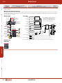
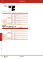
FS1A Multi-function Safety Relay
Key features:
• No programming required. Configuration complete by turning on a logic switch
• A safety circuit can be configured easily just by selecting a logic from eight preprogrammed logics
• Mode selection, partial/entire stop can be achieved just by selecting a logic
• One SafetyOne module can connect with various safety inputs such as emergency stop
switches and light curtains
• The status of safety I/Os and the SafetyOne errors can be monitored
• Solenoid drive output is provided, eliminating the need for a PLC
• IEC 61508 safety integrity level 3, ISO 13849-1 performance level e,
and EN954-1 control category 4 compliant
Interlock Switches
Part Numbers
Optional Parts
No. of Logic
Part Number
8
FS1A-CO1S
24
FS1A-C11S
Enabling Switches
Logic selection only!
Simple DIP switch selection
Product
Part Number
Input Connector
FS9Z-CN01
Output Connector
FS9Z-CN02
Connecting Tool
FS9Z-SD01
Marked Cable Tie
FS9Z-MT01
Used to lock the protective cover
of the FS1A.
DIN Rail
BNDN1000
Aluminum, 1m 35mm wide
End Clip
BNL6
No tools required
No programming or debugging
Safety Control
No program certification required
Complies with key safety standards!
International
Standards
Compliant
Light Curtains
ISO13849-1 PLe
The SafetyOne satisfies:
EN 954-1
IEC 61508
ISO 13849-1
Category 4
SIL3
Performance level e
ISO IEC EN ANSI/RIA
ANSI SEMI NFPA
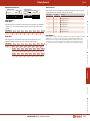
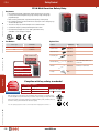
With 8 (FS1A-C01S) or 24 (FS1A-C11S) pre-programmed safety circuit logics in a compact housing,
the FS1A SafetyOne safety controller allows you to build a safety circuit by just sliding a DIP switch.
Because the programs are tested and approved for compliance with key safety standards, labor, cost,
and time for safety system certification can be reduced greatly.
AS-Interface Safety at Work
Note: The eight logic programs of FS1A-C01S are not included in the 24 logic programs of FS1A-C11S.
416 www.IDEC.com
Note
Safety Control
FS1A
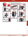
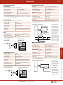
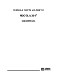
Large functionality in a compact housing!
-ONE
ALL-IN
Replaces more than seven
safety relay modules
Overview
Small
&
Compact
Two-hand Control
Emergency
Stop Switch
FS1A-C11S
Logic 12A
Interlock
Switch
Monitor Output
Safety
Output 1
Safety
Output 2
Safety Outputs
PLC
Two-hand
Control
Monitor signals
Mode selection
Error signals
72 mm
Emergency
Stop
Switch
114.5 mm
Hazardous
area
Muting sensors
FS1A-C11S
Logic 103
Light
Curtain
Safety
Output 1
Enabling
Switch
Safety
Output 2
Selector
Switch
Object
113.5 mm
Muting lamp
Interlock Switches
Muting function of light curtains
Light curtains
XW Series E-Stops
Light Curtain
(PNP)
Interlock
Switch
Solenoid drive output
Safety Input
Enabling
Switch
Selector
Switch
Solenoid drive
output
Interlock
Switch
Enabling Switches
Four safety output lines
Emergency
Stop Switch
FS1A-C11S
Logic 104
Safety
Output 2
Safety
Output 1-1
Safety
Output 1-2
Safety
Output 3
Safety Control
Light Curtains
AS-Interface Safety at Work
800-262-IDEC (4332) • USA & Canada
417
Safety Control
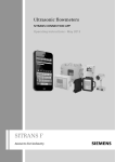
Overview
FS1A
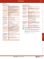
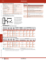
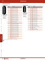
Output Lines
Input Device 1
1 line
Mode select
necessary
(Two dual safety
outputs of the same
operation)
Mode select
unnecessary
Input Device 2
Input Device 3
Light curtain
Using the muting function
of FS1A
004 FS1A-C01S
Not using the muting
function of FS1A
003 FS1A-C01S
002 FS1A-C01S
001 FS1A-C01S
XW Series E-Stops
Other devices
(Two dual safety
outputs of different
operations)
Mode select
necessary
FS1A
006 FS1A-C01S
NO/NC contact
device
2 lines
Logic
No.
Light curtain
005 FS1A-C01S
Not using the muting
function of FS1A
103 FS1A-C11S
13b FS1A-C11S
13C FS1A-C11S
13d FS1A-C11S
103 FS1A-C11S
Interlock Switches
13A FS1A-C11S
13b FS1A-C11S
Other devices
13C FS1A-C11S
START
13d FS1A-C11S
Mode select
unnecessary
12A FS1A-C11S
Two-hand control
Using the muting function
of FS1A
11A FS1A-C11S
Light curtain
Enabling Switches
11d FS1A-C11S
Not using the muting
function of FS1A
C
a
t
e
g
o
r
y
4
11C FS1A-C11S
102 FS1A-C11S
12C FS1A-C11S
NO/NC contact
device
11b FS1A-C11S
007 FS1A-C01S
008 FS1A-C01S
101 FS1A-C11S
11A FS1A-C11S
Safety Control
Other devices
11C FS1A-C11S
102 FS1A-C11S
12b FS1A-C11S
12C FS1A-C11S
4 lines
(Four single safety
outputs of different
operations)
Mode select
necessary
Light curtain
Not using the muting
function of FS1A
14d FS1A-C11S
108 FS1A-C11S
Light Curtains
104 FS1A-C11S
14A FS1A-C11S
14b FS1A-C11S
Other devices
14C FS1A-C11S
14b FS1A-C11S
108 FS1A-C11S
AS-Interface Safety at Work
Mode select
unnecessary
Light curtain
Not using the muting
function of FS1A
105 FS1A-C11S
106 FS1A-C11S
105 FS1A-C11S
Other devices
106 FS1A-C11S
107 FS1A-C11S
418 www.IDEC.com
C
a
t
e
g
o
r
y
3
Safety Control
FS1A
Specifications
Electric Characteristics
Safety Circuit
Logic selection
Operating Temperature
–10 to +55°C (no freezing)
Operating Humidity
10 to 95% RH (no condensation)
Storage Temperature
–40 to +70°C (no freezing)
Storage Humidity
10 to 95% RH (no condensation)
Pollution Degree
2 (IEC/EN60664-1)
Applicable Standards
Free from corrosive gases
Altitude
Operation: 0 to 2000m, Transport: 0 to 3000m
Vibration Resistance
5 to 8.4 Hz, amplitude 3.5 mm
Vibration:
8.4 to 150 Hz
Acceleration: 9.8 m/s2 (2 hours each on three
mutually perpendicular axes)
(IEC/EN60028-2-6)
Bump: Acceleration 98 m/s2, 16 ms (1000 times
each on three mutually perpendicular axes)
(IEC/EN60028-2-29)
Shock Resistance
147 m/s2, 11ms (3 shocks each on three mutually
perpendicular axes (IEC/EN 60028-2-27)
Connector Insertion/
Removal Durability
50 times maximum
Configuration Switch
Durability
100 operations maximum per pole
Enter Button Durability
1000 operations maximum
Housing Material
Modified-polyphenyleneether (m-PPE)
Weight (approx.)
330g
20.4 to 28.8V DC
Maximum Power
Consumption
48W (at the rated power voltage, when all I/Os are
ON) (incl. output load)
Allowable Momentary
Power Interruption
10 ms minimum (at the rated power voltage)
Response Time
ON–OFF: 40 ms maximum 1
100 ms maximum 2
OFF–ON: 100 ms maximum 3
Start-up Time 4
6 sec maximum
Dielectric Strength
Between live part and FE terminal:
500V AC, 1 minute
Between housing and FE terminal:
500V AC, 1 minute
Insulation Resistance
Between live part and FE terminal:
10 MΩ minimum (500V DC megger)
Between housing and FE terminal:
10 MΩ minimum (500V DC megger)
Impulse Noise Immunity
(noise simulator)
Power terminal: ±1 kV 50 ns, 1μs
(direct connection)
I/O terminal: ±2kV 50 ns, 1μs (coupling adapter)
Inrush Current
25A maximum
Ground
Ground resistance of 100Ω maximum
Effect of Incorrect
Wiring
Reverse polarity: No operation, no damage
Improper voltage: Permanent damage may occur
1. The time to shut off safety outputs after inputs are turned off or input monitor error is
detected (when off-delay timer is set to 0s)
2. Time to shut off safety outputs after an error (except input monitor error) or a configuration
change of logic or timer is detected (not depending on the off-delay timer value)
3. Auto start—Time to turn on safety outputs after safe inputs are turned on
Manual start—Time to turn on safety outputs after start inputs are turned on
Control start—Time to turn on safety outputs after the start inputs are turned off-on-off
(maintain ON for 0.1 to 5s)
4. Time to change to Run state after power supply is turned on.
Safety Control
IP20 (IEC/EN60529)
Corrosion Immunity
Allowable Voltage Range
Enabling Switches
Degree of Protection
24V DC
Interlock Switches
Rated Voltage
XW Series E-Stops
TÜV approval: IEC/EN 61000-6-2, IEC/EN 61000-6-4,
IEC/EN 61496-1, IEC 61508 Part 1-7,
IEC/EN 62061, ISO 13849-1, ISO 13851 (FS1AC11S), EN 954-1
UL: UL508, CSA C22.2 No. 142
Applicable standards: IEC/EN 60204-1, IEC/EN
61131-2, ISO 10218-1, ANSI/RIA R15.06,
ANSI B11.19, SEMI S2-0706, NFPA79
EN 954-1, 13849-1, 62061, 61496-1, 60204-1,
61131-2, 61000-6-2, 61000-6-4
ANSI/RIA R15.06
ANSI B11.19
SEMI S2
NFPA 79
Overview
Operating Environment
Light Curtains
AS-Interface Safety at Work
800-262-IDEC (4332) • USA & Canada
419
Safety Control
FS1A
Overview
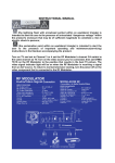
Examples
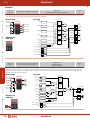
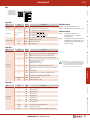
FS1A-C11S
Logic 105
Enabling Switches
Interlock Switches
XW Series E-Stops
(PHUJHQF\
6WRS6ZLWFK
Safety Control
Category
3
Logic 105 is used for safeguarding measures of machine tools and robots, which use safety equipment such as light curtains with dual solid state outputs. Safety outputs are single
output. Five dual channel safety inputs can be connected. Safety output 4 has an off-delay timer.
Wiring Example
Logic Chart
6DIHW\2XWSXW
/LJKW&XUWDLQ
313W\SH
6DIHW\2XWSXW
6DIHW\2XWSXW
6DIHW\2XWSXW
+ROG
6HOIKROG
IXQFWLRQ
7ULJJHU
6HOIKROGIXQFWLRQFLUFXLW
6DIHW\,QSXW
'XDO&KDQQHO6DIHW\
;;
+ROG
6HOIKROG
IXQFWLRQ
7ULJJHU
6HOIKROGIXQFWLRQFLUFXLW
6DIHW\,QSXW
'XDO&KDQQHO6DIHW\
;;
+ROG
6HOIKROG
IXQFWLRQ
7ULJJHU
6HOIKROGIXQFWLRQFLUFXLW
6DIHW\,QSXW
'XDO&KDQQHO6DIHW\
;;
DIP Switch and
LED Display
FS1A-C11S
Logic 13b
6HOIKROGIXQFWLRQFLUFXLW
6DIHW\,QSXW
'XDO&KDQQHO6DIHW\
;;
/RJLF
+ROG
6HOIKROG
IXQFWLRQ
7ULJJHU
6HOIKROGIXQFWLRQFLUFXLW
6DIHW\,QSXW
'XDO&KDQQHO6DIHW\
;;
6WDUW,QSXW
;
0RQLWRU,QSXW
6WDUW,QSXW
;
0RQLWRU,QSXW
([WHUQDO'HYLFH0RQLWRU
7;
('0
([WHUQDO
'HYLFH
0RQLWRU
([WHUQDO'HYLFH0RQLWRU
7;
('0
([WHUQDO
'HYLFH
0RQLWRU
([WHUQDO'HYLFH0RQLWRU
7;
('0
([WHUQDO
'HYLFH
0RQLWRU
([WHUQDO'HYLFH0RQLWRU
7;
('0
([WHUQDO
'HYLFH
0RQLWRU
+ROG
6HOIKROG
IXQFWLRQ
7ULJJHU
&RQWURO
Safety
Output +ROG
<
266'
Safety
Output ('0
<
+ROG
266'
Safety
Output ('0
<
+ROG
266'
Safety
Output ('0
<
+ROG
266'
ZLWK
2IIGHOD\
('0
&RQWURO
6WDUW
Output Line: 2
2 dual safety outputs of
different operations
The logic constructing an OR circuit applicable
for selection of active safety input devices
Category
4
In machine tools and robots, a hazard source is isolated by a guard in automatic operation. In human-attended operation such as teaching and maintenance, the operator has to work
inside a hazardous area. Logic 13b is used to configure a system in which teach or auto mode can be selected using a selector switch. Safety outputs are dual channel outputs. OR
circuit can be configured in auto mode. Two dual channel direct opening input, one mode select input, one dual channel dependent input, and two dual channel safety inputs can be
connected. Safety output 2 has an off-delay timer.
Wiring Example
Logic Chart
/RJLFE
(PHUJHQF\
6WRS6ZLWFK
(QDEOLQJ
6ZLWFK
6DIHW\2XWSXW
6HOHFWRU
6ZLWFK
,QWHUORFN
6ZLWFK
Light Curtains
Output Line: 4
4 single safety outputs of different operations
Partial stop logic for apparatus with openings
/LJKW&XUWDLQ
313W\SH
6DIHW\2XWSXW
6DIHW\,QSXW
7;7;
'XDO&KDQQHO
'LUHFW2SHQLQJ
6DIHW\,QSXW
7;7;
'XDO&KDQQHO
'HSHQGHQW
6DIHW\,QSXW
7;;
6DIHW\,QSXW
7;7;
0RGH6HOHFW
AS-Interface Safety at Work
420 6HOIKROG
IXQFWLRQ
7ULJJHU
7HDFK0RGH
$XWR0RGH
'XDO&KDQQHO
'LUHFW2SHQLQJ
6DIHW\,QSXW
'XDO&KDQQHO6DIHW\
;;
DIP Switch and
LED Display
6HOIKROGIXQFWLRQ
FLUFXLW
+ROG
6DIHW\,QSXW
'XDO&KDQQHO6DIHW\
;;
6WDUW,QSXW
;
0RQLWRU,QSXW
6WDUW,QSXW
;
0RQLWRU,QSXW
([WHUQDO'HYLFH0RQLWRU
7;
('0
([WHUQDO
'HYLFH
0RQLWRU
([WHUQDO'HYLFH0RQLWRU
7;
('0
([WHUQDO
'HYLFH
0RQLWRU
! 6HOIKROGIXQFWLRQ
FLUFXLW
+ROG
6HOIKROG
IXQFWLRQ
7ULJJHU
6HOIKROGIXQFWLRQ
FLUFXLW
+ROG
6HOIKROG
IXQFWLRQ
7ULJJHU
! 6DIHW\2XWSXW
<
+ROG
266'
('0
6DIHW\2XWSXW
+ROG
266'
ZLWK
2IIGHOD\
('0
&RQWURO
&RQWURO
6WDUW
www.IDEC.com
<
<
<
Safety Control
Output Line: 2
2 dual safety outputs of
different operations
Partial stop logic applicable for selection of active safety input devices
Category
4
Overview
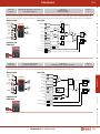
FS1A-C11S
Logic 13C
FS1A
In machine tools and robots, a hazard source is isolated by a guard in automatic operation. In human-attended operation such as teaching and maintenance, the operator has to work
inside a hazardous area. Logic 13C is used to configure a system in which teach or auto mode can be selected using a selector switch. Safety outputs are dual channel outputs. Three
dual channel direct opening inputs, one mode select input, one dual channel dependent input, one dual channel safety input can be connected. Safety output 2 has an off-delay timer.
Wiring Example
(PHUJHQF\
6WRS6ZLWFK
Logic Chart
/RJLF&
6DIHW\,QSXW
7;7;
6DIHW\2XWSXW
6HOHFWRU
6ZLWFK
,QWHUORFN
6ZLWFK
6DIHW\2XWSXW
/LJKW&XUWDLQ
313W\SH
'XDO&KDQQHO
'HSHQGHQW
6DIHW\,QSXW
7;;
0RGH6HOHFW
6DIHW\,QSXW
7;7;
'XDO&KDQQHO
'LUHFW2SHQLQJ
6DIHW\,QSXW
7;7;
'XDO&KDQQHO
'LUHFW2SHQLQJ
7ULJJHU
6HOIKROG
IXQFWLRQFLUFXLW
+ROG
6HOIKROG
IXQFWLRQ
7ULJJHU
7HDFK0RGH
$XWR0RGH
6HOIKROG
IXQFWLRQFLUFXLW
0RQLWRU,QSXW
6WDUW,QSXW
;
0RQLWRU,QSXW
([WHUQDO'HYLFH0RQLWRU
7;
('0
([WHUQDO
'HYLFH
0RQLWRU
([WHUQDO'HYLFH0RQLWRU
7;
('0
([WHUQDO
'HYLFH
0RQLWRU
<
266'
('0
6DIHW\2XWSXW
6HOIKROG
IXQFWLRQFLUFXLW
+ROG
6HOIKROG
IXQFWLRQ
7ULJJHU
<
+ROG
<
266'
ZLWK
2IIGHOD\
('0
&RQWURO &RQWURO
6WDUW
Output Line: 2
2 dual safety outputs of different operations
Enabling Switches
The logic for apparatus with
a two-hand control device
<
+ROG
Interlock Switches
6WDUW,QSXW
;
6DIHW\2XWSXW
! +ROG
6HOIKROG
IXQFWLRQ
7ULJJHU
6DIHW\,QSXW 'XDO&KDQQHO6DIHW\
;;
DIP Switch and
LED Display
FS1A-C11S
Logic 12A
6DIHW\,QSXW
7;7;
XW Series E-Stops
(QDEOLQJ
6ZLWFK
6HOIKROG
IXQFWLRQFLUFXLW
+ROG
6HOIKROG
IXQFWLRQ
'XDO&KDQQHO
'LUHFW2SHQLQJ
Category
4
Logic 12A is used for safeguarding measures of machine tools that use two-hand control. Safety outputs are dual channel outputs. Two dual channel direct opening inputs, one twohand control input (two safety inputs = one point), and two dual channel safety inputs can be connected. Safety output 2 has an off-delay timer.
Wiring Example
(PHUJHQF\
6WRS
6ZLWFK
Logic Chart
/RJLF$
/LJKW&XUWDLQ
3137\SH
7ZRKDQG
&RQWURO
6DIHW\
2XWSXW
6DIHW\,QSXW
7;7;
'XDO&KDQQHO
'LUHFW2SHQLQJ
6HOIKROGIXQFWLRQFLUFXLW
6DIHW\,QSXW
'XDO&KDQQHO6DIHW\
;;
6DIHW\2XWSXW
<
+ROG
+ROG
6HOIKROG
IXQFWLRQ
266'
<
('0
7ULJJHU
6DIHW\,QSXW
'XDO&KDQQHO6DIHW\
;;
6DIHW\2XWSXW
6DIHW\,QSXW
7;7;
'XDO&KDQQHO
121&
6DIHW\,QSXW
6DIHW\,QSXW
7;7;
'XDO&KDQQHO
121&
6DIHW\,QSXW
6WDUW,QSXW
;
0RQLWRU,QSXW
6WDUW,QSXW
;
0RQLWRU,QSXW
([WHUQDO'HYLFH0RQLWRU
7;
('0
([WHUQDO
'HYLFH
0RQLWRU
([WHUQDO'HYLFH0RQLWRU
7;
('0
([WHUQDO
'HYLFH
0RQLWRU
7ZRKDQG
FRQWURO
7\SH,,,&
+ROG
266'
ZLWK
2IIGHOD\
<
<
('0
N
&RQWURO
Light Curtains
DIP Switch and
LED Display
6DIHW\
2XWSXW
'XDO&KDQQHO
'LUHFW2SHQLQJ
Safety Control
,QWHUORFN
6ZLWFK
6DIHW\,QSXW
7;7;
&RQWURO
6WDUW
AS-Interface Safety at Work
800-262-IDEC (4332) • USA & Canada
421
Safety Control
FS1A
Overview
FS1A-C01S
Logic 004
Muting function logic for apparatus
with openings
Output Line: 1
2 dual safety outputs of the same operation
Category
4
In Logic 004, muting functions are added to the dual solid state output of Logic 003. Dual direct-opening components such as emergency stop switches and interlock switches can be
used at the same time.
Muting Function Improves Productivity
XW Series E-Stops
With a muting function, the system stops when detecting a human and temporarily defeats the light curtain while work objects are being supplied. This improves the system’s productivity. Muting functions can be used easily by connecting a light curtain, muting sensor, and muting lamp to the SafetyOne (Note). In muting status, the OFF signals of corresponding
safety solid state outputs are defeated.
Wiring Example
Logic Chart
+D]DUGRXV$UHD
0XWLQJ6HQVRU
/LJKW&XUWDLQ
1RWH
0DNHVXUHWKDWWKH
LQWHUVHFWLRQRI
RSWLFDOD[HVLVZLWKLQ
WKHKD]DUGRXVDUHD
Interlock Switches
2EMHFW
/LJKW&XUWDLQ
313W\SH
0XWLQJ6HQVRU
313W\SH
/LJKW&XUWDLQ
313W\SH
0XWLQJ6HQVRU
313W\SH
DIP Switch and
LED Display
/RJLF
6DIHW\2XWSXW
6DIHW\2XWSXW
0XWLQJ/DPS
'XDO&KDQQHO6DIHW\
0XWLQJ,QSXW
;;
0XWLQJ,QSXW
6DIHW\,QSXW
;;
'XDO&KDQQHO6DIHW\
0XWLQJ,QSXW
;;
0XWLQJ,QSXW
6DIHW\,QSXW
0XWLQJIXQFWLRQ
6DIHW\,QSXW
7;7;
'XDO&KDQQHO
'LUHFW2SHQLQJ
6DIHW\,QSXW
7;7;
'XDO&KDQQHO
'LUHFW2SHQLQJ
6WDUW,QSXW
;
0RQLWRU,QSXW
6WDUW,QSXW
;
0RQLWRU,QSXW
([WHUQDO'HYLFH0RQLWRU
7;
('0
([WHUQDO
'HYLFH
0RQLWRU
([WHUQDO'HYLFH0RQLWRU
7;
('0
([WHUQDO
'HYLFH
0RQLWRU
0XWLQJ
0XWLQJIXQFWLRQ
0XWLQJ
6DIHW\2XWSXW
+ROG
6HOIKROG
IXQFWLRQ
7ULJJHU
<
+ROG
266'
ZLWK
2IIGHOD\
<
('0
6DIHW\2XWSXW
+ROG
N
&RQWURO
&RQWURO
6WDUW
266'
ZLWK
2IIGHOD\
('0
Note: When installing light curtain and muting sensor, ensure safety by referring to IEC TS 62046 technical documents.
Light Curtains
AS-Interface Safety at Work
422 Note: Use light curtains, muting sensors, and muting
lamps which meet the safety regulations or
safety category of the country or regions where
the products are used. Otherwise safety cannot
be ensured, resulting in possible danger.
6DIHW\,QSXW
Safety Control
Enabling Switches
(PHUJHQF\
6WRS6ZLWFK
0XWLQJ/DPS
6DIHW\,QSXW
;;
www.IDEC.com
<
<
Safety Control
Safety Input Specifications
Drive Terminals
FS1A
Safety Output Specifications
Output Type
Source output (N channel MOSFET)
Rated Output Voltage
Power supply voltage
Minimum Output Voltage
Power supply voltage – 2.0V
Rated Drive Voltage
Power supply voltage
Minimum Drive Voltage
Power supply voltage – 2.0V
Number of Safety Outputs
4 (Y0, Y1, Y2, Y3)
Number of Drive Terminals
14
1 output
500 mA maximum
Maximum Drive Current
20 mA per terminal (28.8V DC) (Note)
Maximum Output
Current
Total
1A maximum
Note: Drive terminals of safety inputs send safety confirmation signals (pulse signals) for the diagnosis
of safety components and input circuits.
Wiring and diagnosis function change depending on the selected logic. See user’s manual “Chapter
5 Logic.” Basic specifications remain the same.
Leakage Current
Allowable Capacitive Load
1 µF maximum
Receive Terminals
Cable Length 2
100m maximum (total length per output)
0.1 mA maximum
L/R = 25 ms
24V DC
Input ON Voltage
15.0 to 28.8V DC
Input OFF Voltage
Open or 0 to 5.0V DC
Number of Inputs
14
Input Current
10 mA per terminal (at the rated power voltage)
Input Signal
Sink input (for PNP output), Type 1 (IEC61131-2)
9
,QWHUQDO
&LUFXLW
/RJLF
&LUFXLW
Wire
Cable Length (Note)
100m maximum (total wire length per input)
Allowable Wire Resistance
300Ω maximum
2IIF\FOH
$SSUR[PV
Note: When wiring between the SafetyOne and a component is 30m or more, use shielded cable to
ensure electromagnetic immunity.
21
2))
5HFHLYH7HUPLQDO
2SHUDWLQJ5DQJH
2IIWLPH$SSUR[V
9ROWDJH9
N
Monitor Output Specifications
215DQJH
,QWHUQDO&LUFXLW
;Q
7UDQVLWLRQ
5DQJH
9²
2))5DQJH
Start Input Specifications
Source output (N channel MOSFET)
Rated Output Voltage
Power supply voltage
Minimum Output Voltage
Power supply voltage – 2.0V
Number of Safety Outputs
4 (Y0, Y1, Y2, Y3)
Maximum Output
Current
1 output
500 mA maximum
Total
1A maximum
Leakage Current
0.1 mA maximum
Safety Control
&XUUHQW
P$
Output Type
Rated Input Voltage
24V DC
Allowable Inductive Load 1
L/R = 25 ms
Input ON Voltage
15.0 to 28.8V DC
Allowable Capacitive Load
1 µF maximum
Input OFF Voltage
Open or 0V to 5.0V DC
Cable Length
100m maximum (total length per output)
Number of Start Inputs
2 (X16, X17)
Input Current
5 mA per terminal (at the rated power voltage)
Input Signal
Sink input (PNP output), Type 1 (IEC61131-2)
Cable Length (Note)
100m maximum (total wire length per input)
Allowable Wire Resistance
300Ω maximum
Note: When wiring between the SafetyOne and a component is 30m or more, use shielded cable to
ensure electromagnetic immunity.
6WDUW,QSXW2SHUDWLRQ5DQJH
9
,QWHUQDO
&LUFXLW
/RJLF
&LUFXLW
<Q
9ROWDJH9
,QWHUQDO&LUFXLW
;;
N
9²
215DQJH
9²
7UDQVLWLRQ
5DQJH
2))5DQJH
&XUUHQW
P$
800-262-IDEC (4332) • USA & Canada
423
AS-Interface Safety at Work
The operating characteristics of the monitor
output change depending
on the selected logic. For
details, see user’s manual “Chapter 5 Logic.”
The basic specifications
remain the same.
Do not use monitor
output as a safety output,
otherwise the system’s
safety cannot be assured
when the SafetyOne or
safety components fail.
Light Curtains
0RQLWRU2XWSXW,QWHUQDO&LUFXLW
Note: When wiring between the SafetyOne and a component is 30m or more, use shielded cable to
ensure electromagnetic immunity.
6WDUW,QSXW,QWHUQDO&LUFXLW
2
Enabling Switches
The safety outputs of the
SafetyOne are solid state
outputs. When the output is
on, off-check signals are generated at regular intervals.
The operating characteristics
of the safety output change
depending on the selected
logic. For details, see user’s
<WR< manual “Chapter 5 Logic.”
The basic specifications
remain the same.
9²
Note that off-check signals
may cause reaction of some
safety components depending on their response speed.
Monitor output and solenoid/
lamp output do not generate
outputs of off-check signals.
6DIHW\2XWSXW,QWHUQDO&LUFXLW
Interlock Switches
Rated Input Voltage
XW Series E-Stops
Allowable Inductive Load
1
1. When connecting an inductive load, connect a protection element such as a diode.
2. When wiring between the SafetyOne and a component is 30m or more, use shielded cable to ensure
electromagnetic immunity.
(X0, X1, X2, X3, X4, X5, X6, X7, X10, X11, X12, X13, X14, X15)
5HFHLYH7HUPLQDO
,QWHUQDO&LUFXLW
Overview
(T0, T1, T2, T3, T4, T5, T6, T7, T10, T11, T12, T13, T14, T15)
Safety Control
FS1A
XW Series E-Stops
Overview
Solenoid/Lamp Output Specifications
Source output (N channel MOSFET)
Rated Output Voltage
Power supply voltage
Minimum Output Voltage
Power supply voltage – 2.0V
No. of Solenoid/Lamp Outputs
2 (Y17, Y20)
Maximum Output
Current
1 output
500 mA maximum
Total
500 mA maximum
Leakage Current
0.1 mA maximum
Allowable Inductive Load 1
L/R = 25 ms
Cable Length 2
100m maximum (total length per output)
1. When connecting an inductive load, connect a protection element such as a diode.
2. When wiring between the SafetyOne and a component is 30m or more, use shielded cable to ensure
electromagnetic immunity.
Solenoid/Lamp Output Internal Circuit
9
Interlock Switches
Internal States
Output Type
,QWHUQDO
&LUFXLW
/RJLF
&LUFXLW
<
<
9²
State
Description
Initial
Initial processing is performed immediately after power is supplied to
the SafetyOne. The internal circuits are checked and the LEDs show
operation confirmation (blinking) for 6 seconds (approx).
Run
The SafetyOne is under normal operation. Logic processing continues
without failures or wiring errors.
Configuration
A logic or off-delay timer value is being configured. Configuration
enables the logic and off-delay timer value. When completed, the
SafetyOne changes to the Run state.
Protection
An input monitor error has occurred with dual channel input, EDM input,
or muting input. When the problem is removed, the SafetyOne changes
to Run state.
Stop
A failure or error has occurred with an external device or internal
circuit. When the problem is removed and the power is turned on, Stop
state is cleared.
The selected operating characteristics of solenoid/lamp output change
depending on the selected logic. For
details, see user’s manual “Chapter
5 Logic.” The basic specifications
remain the same. Do not use solenoid/lamp output as a safety output,
otherwise the system’s safety cannot
be assured when the SafetyOne or
safety components fail.
AS-Interface Safety at Work
Light Curtains
Safety Control
Enabling Switches
LED and Output States
When safety outputs are dual channel outputs
Logic
LED
Error
LED
Timer
LED
Safety Output
Solenoid/
Lamp Output
Y0 to Y3
Y17, Y20
Y4 to Y13
Y14
Y15
Y16
Initial
(Note 1)
(Note 1)
(Note 1)
OFF
OFF
OFF
ON
ON
OFF
Run
Logic #
Blank
Selected
Value
(Note 2)
(Note 2)
(Note 2)
OFF
OFF
ON
Configuration
(Note 3)
C
(Note 3)
OFF
OFF
OFF
OFF
ON
OFF
Protection
Logic #
1
Selected
Value
Off
(Note 6)
OFF
(Note 4)
OFF
ON
OFF
Stop
Blank
(Note 5)
Blank
OFF
OFF
(Note 4)
ON
ON or OFF
OFF
State
Monitor Output
When safety outputs are single channel outputs
Timer
LED
Safety Output
Y0 to Y3
Y4 to Y13, Y17, Y20
Y14
Y15
Y16
(Note 1)
(Note 1)
OFF
OFF
ON
ON
OFF
(Note 2)
(Note 2)
OFF
OFF
ON
State
Logic
LED
Error
LED
Initial
(Note 1)
Monitor Output
Run
Logic #
Blank
Selected
Value
Configuration
(Note 3)
C
(Note 3)
OFF
OFF
OFF
ON
OFF
Protection
Logic #
1
Selected
Value
Off
(Note 6)
(Note 4)
OFF
ON
OFF
Stop
Blank
(Note 5)
Blank
OFF
(Note 4)
ON
ON or OFF
OFF
1.
2.
3.
4.
Random display of Initial state.
5. Error number is displayed.
Output and LED display of the selected logic.
6. Safety output with timer is turned OFF after set OFF-delay time.
Blinking LED display of the selected logic number or the selected timer value. Caution: Solenoid/lamp outputs (Y17, Y20) turn on for 1 second maximum when
Pulsing display of monitor output and output LED corresponding to the input
the state changes to Run state. Take operation of connected components into
consideration.
of error. Other LEDs and monitor outputs maintain the display of Run state.
424 www.IDEC.com
Safety Control
FS1A
LEDs
e
Overview
c/RJLF/('JUHHQ
LOGIC
d(UURU/('UHG
c
e7LPHU/('JUHHQ
f,QSXW/('RUDQJH
Q2XWSXW/('RUDQJH
0 .1 .5 1 2 5 15 30
ERROR
d
f
TIMER(S)
SAFE-IN
X0
X1 SAFE-OUT
X2
X3
Y0
Y1
X4
X5
Y2
Y3
X6
X7
X10
X11
X12
X13
X14
X15
SOLENOID
-OUT
Y17
Y20
Q
START-IN
X16
X17
Logic LED
LED
FS1A-C01S
1, 2, 3, 4, 5, 6, 7, 8
FS1A-C11S
1, 2, 3, 4, 5, 6, 7, 8,
A, b, C, d
ON
Description
Blink
ON
FS1A-C01S setting
The selected logic is in Configuration state
Correct: Selecting one logic from 1 to 8
Wrong: Selecting two or more logics from 1 to 8
The selected logic is in Run or Protection state
(Ex. Logic 14A: 4 A 4 A 4 ...)
FS1A-C11S setting
The selected logic is in Run or Protection state
Blink
The selected logic is in Configuration state
(Ex. Logic 14A: 4 A OFF A 4 OFF...)
E
Blink
The selected logic has Configuration error (logic not selected, or
multiple logics are selected)
Random
ON/Blink
OFF
OFF
LED
Status
1
ON
Input monitor error (Protection state)
2
ON
Wiring error at safety input or an error in safety input circuits
3
ON
Wiring error at start input or an error in start input circuit
4
ON
Wiring error at safety output or an error in safety output circuit
5
ON
Muting lamp error (disconnection)
(FS1A-C01S: logic 4 only)
(FS1A-C11S: logic 11d only)
6
ON
Power supply error or internal power supply circuit error
7
ON
Internal error, power supply error, or internal power supply circuit
error
9
ON
EMC disturbance
ON
Configuration procedure is in progress (Configuration state)
Initializing (Initial state)
Error (Stop state)
Correct:
Wrong:
Selecting one logic from 1 to 8
Selecting one from 1 to 4, and one
from A, b, C, or d.
Selecting three or more logics from 1 to 8
Selecting two or more logics from 1 to 4
Selecting two or more logics from A (5),
b (6), C (7), or d (8)
Error LED
Type
Blink
Note: Blinks for 1 to 5 seconds after the enter button is
pressed. Releasing the button during blinking activates
the setting. The blinking LED becomes ON if the button
is pressed for more than 5 seconds, and the setting
becomes invalid even after the button is released.
Safety Control
C
Description
Configuration is valid (Note) (Configuration state)
Random
ON/Blink
OFF
OFF
LED
Status
0
ON
No off-delay (safety outputs shut down immediately)
.1
ON
Off-delay timer 0.1s
.5
ON
Off-delay timer 0.5s
1
ON
Off-delay timer 1s
2
ON
Off-delay timer 2s
Enabling Switches
FS1A-C01S/
FS1A-C11S
Interlock Switches
FS1A-C01S/ C11S
Status
XW Series E-Stops
Type
Initializing (Initial state)
Normal operation (Run state)
Timer LED
Type
ON
Off-delay timer 5s
ON
Off-delay timer 15s
30
ON
Off-delay timer 30s
Each LED
Blink
Random
ON/Blink
All LEDs
OFF
AS-Interface Safety at Work
5
15
Light Curtains
FS1A-CO1S/
FS1A-C11S
Description
Selected timer value (Configuration state)
Initializing (Initial state)
Timer value is not selected or the SafetyOne is in Stop state
800-262-IDEC (4332) • USA & Canada
425
Safety Control
FS1A
Overview
LEDs, con’t
c/RJLF/('JUHHQ
LOGIC
d(UURU/('UHG
c
e7LPHU/('JUHHQ
f,QSXW/('RUDQJH
Q2XWSXW/('RUDQJH
e
0 .1 .5 1 2 5 15 30
ERROR
d
f
SAFE-IN
TIMER(S)
X0
X1 SAFE-OUT
X2
X3
Y0
Y1
X4
X5
Y2
Y3
X6
X7
X10
X11
X12
X13
X14
X15
SOLENOID
-OUT
Y17
Y20
Q
START-IN
XW Series E-Stops
X16
Input LED
SAFE-IN (X0 to X15), START-IN (X16, X17)
Type
LED
X0 to X15
FS1A-C01S
Enabling Switches
Interlock Switches
X16, X17
X0 to X15
FS1A-C11S
X16, X17
Status
Description
ON
Input ON
OFF
Input OFF, Stop/Configuration state
Blink
Input monitor error
ON
Input ON
OFF
Input OFF, Stop/Configuration state
ON
Input ON
OFF
Input OFF, Stop/Configuration state
Blink
Input error (error displayed on error LED)
ON
Input ON
OFF
Input OFF, Stop/Configuration state
Blink
Input error (error displayed on error LED)
Ourput LED
SAFE-OUT (Y0 to Y3), SOLENOID-OUT (Y17, Y20)
Type
LED
Y0 to Y3
FS1A-C01S
Y17, Y20
Y0 to Y3
FS1A-C11S
Y17, Y20
Status
Description
ON
Output ON
OFF
Output OFF, Stop/Configuration state
Blink
Off-delay operating
ON
Output ON
OFF
Output OFF, Stop/Configuration state
ON
Output ON
OFF
Output OFF
Blink
Off-delay operating, or output error (error displayed on error LED)
ON
Output ON
OFF
Output OFF
Blink
Off-delay operating, or output error (error displayed on error LED)
AS-Interface Safety at Work
Light Curtains
Safety Control
X17
426 www.IDEC.com
Safety Control
Configuration Switches
・FS1A-C01S
TYPE : FS1A-C11S ENTER
LOGIC No.1
TIMER (S)
A b C d
TIMER (S)
1 2 3 4 5 6 7 8
0 .1 .5 1 2 5 15 30
Logic Switch
Timer Switch
・FS1A-C11S
1 2 3 4 5 6 7 8
Eight DIP switches are provided for selecting an off-delay timer value, by moving
a switch upward. Only one timer switch can be selected.
0 .1 .5 1 2 5 15 30
Switch No.
Timer Switch Enter button
Logic Switch
FS1A-C01S
DIP Switch
Logic
1
2
3
4
5
6
7
8
001
002
003
004
005
006
007
008
0
No off-delay (safety outputs shut down immediately)
.1
Off-delay timer 0.1s
3
.5
Off-delay timer 0.5s
4
1
Off-delay timer 1s
5
2
Off-delay timer 2s
6
5
Off-delay timer 5s
7
15
Off-delay timer 15s
8
30
Off-delay timer 30s
2
3
4
5
6
7
8
002
003
004
005
006
007
008
1+A
1+b
1+C
1+d
2+A
2+b
2+C
2+d
11A
11b
11C
11d
12A
12b
12C
12d
3+A
3+b
3+C
3+d
4+A
4+b
4+C
4+d
13A
13b
13C
13d
14A
14b
14C
14d
Enabling Switches
1
001
The enter button is used to activate the configuration of logic and timer switches. Error LED
will blink for 1 to 5 seconds after pressing the enter button. Releasing the button during
blinking activates the setting. The blinking LED becomes ON if the button is pressed for
more than 5 seconds, and the setting becomes invalid even after the button is released.
For setting the switches and enter button, use the setting tool supplied with the SafetyOne.
Interlock Switches
Eight DIP switches are provided for selecting a logic by moving one or two
switch(es) upward. For details, see user’s manual “Chapter 5 Logic.”
DIP Switch
1
2
Enter Button
FS1A-C11S
Logic
Description
XW Series E-Stops
Eight DIP switches are provided for selecting a logic by moving a switch upward.
For details, see user’s manual “Chapter 5 Logic.” Only one logic switch can be
selected.
Timer Value
Overview
ENTER
LOGIC No.
FS1A
Safety Control
Light Curtains
AS-Interface Safety at Work
800-262-IDEC (4332) • USA & Canada
427
Safety Control
FS1A
Overview
Connector Specifications
Input Connector
T0
X0
T1
X1
T3
X3
T4
X4
T5
X5
T2
T6
T7
T10
X6
X7
X10
Description
T0
A1
Safety input drive terminal 0
T1
A2
Safety input drive terminal 1
T2
A3
Safety input drive terminal 2
<
<
<
<
<
<
<
<
<
<
<
<
<
<
<
<
1&
X11
T3
A4
Safety input drive terminal 3
T12
X12
9
9²
T13
X13
Safety input drive terminal 4
)(
X14
A5
)(
T14
T4
T15
X15
T5
A6
Safety input drive terminal 5
T6
A7
Safety input drive terminal 6
X16
X17
Applicable connector
• Spring clamp (30-pin)
FS9Z-CN01 (IDEC)
2-1871940-5
(Tyco Electronics)
Enabling Switches
Interlock Switches
• Crimp (30-pin)
2-1871946-5
(Tyco Electronics)
$SSOLFDEOHFRQQHFWRU
6SULQJFODPSSLQ
)6=&1,'(&
7\FR(OHFWURQLFV
&ULPSSLQ
7\FR(OHFWURQLFV
No.
Description
Y0
A1
Safety output terminal 0
Y2
A2
Safety output terminal 2
Y4
A3
Safety output terminal 4
Y6
A4
Safety output terminal 6
Y10
A5
Safety output terminal 10
Y12
A6
Safety output terminal 12
Y14
A7
Safety output terminal 14
Y16
A8
Safety output terminal 16
Y20
A9
Solenoid/lamp output terminal 20
T7
A8
Safety input drive terminal 7
A9
Safety input drive terminal 10
T11
A10
Safety input drive terminal 11
V+
A10
24V DC power terminal
T12
A11
Safety input drive terminal 12
FE
A11
Functional ground terminal
T13
A12
Safety input drive terminal 13
Y1
B1
Safety output terminal 1
T14
A13
Safety input drive terminal 14
Y3
B2
Safety output terminal 3
T15
A14
Safety input drive terminal 15
Y5
B3
Safety output terminal 5
T16
A15
Start input terminal 16
Y7
B4
Safety output terminal 7
X0
B1
Safety input receive terminal 0
Y11
B5
Safety output terminal 11
X1
B2
Safety input receive terminal 1
Y13
B6
Safety output terminal 13
X2
B3
Safety input receive terminal 2
Y15
B7
Safety output terminal 15
X3
B4
Safety input receive terminal 3
Y17
B8
Solenoid/lamp output terminal 17
X4
B5
Safety input receive terminal 4
NC
B9
Blank terminal
X5
B6
Safety input receive terminal 5
V–
B10
0V DC power terminal
X6
B7
Safety input receive terminal 6
FE
B11
Functional ground terminal
X7
B8
Safety input receive terminal 7
X10
B9
Safety input receive terminal 10
X11
B10
Safety input receive terminal 11
X12
B11
Safety input receive terminal 12
X13
B12
Safety input receive terminal 13
X14
B13
Safety input receive terminal 14
X15
B14
Safety input receive terminal 15
X17
B15
Start input terminal 17
Note: For the specifications of crimp connector, contact Tyco Electronics.
AS-Interface Safety at Work
428 Terminal
T10
Light Curtains
Safety Control
No.
<
T11
XW Series E-Stops
X2
Output Connector
Terminal
www.IDEC.com