1
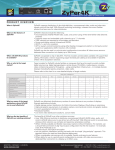
Softkey Codes/Screen Messages
A
The following charts detail the meaning behind the 3-digit code visible above the softkey numbers S1 - S5 on the DCS Remote. The first chart details the codes found when
using the TR button. The second chart features the codes visible when operating a Ps2
engine with operating pantographs. The third chart includes all the features found in all
Ps2 engines. Each chart contains four columns. The first column lists the softkey Code.
The second column contains the 20 character description of the code that will be visible
in the DCS LCD screen when the softkey button is pressed. The third column contains
the 14 character description of the code that is visible when the MORE softkey button is
depressed on the DCS Remote (when operating Ps2 engines). When activated, the
MORE button reveals all of the active softkey functions for the given engine in a list.
The list can be reordered as detailed earlier in this manual. The final column contains a
more readable description of each softkey function.
DCS Remote Icon List
BATT - Low Remote Battery Indicator
(C) - Protocast is active
(D) - Doppler is Active
(L) - Engine is displayed is a Lash-Up
*(M) - External Microphone is active
(P) - Playing back a previously recorded playback session
(R) - Recording a playback session
(T) - Remote is tethered to TIU
(Z) - Z4K track is being controlled
*(M) This feature disables all functionality of the TIU EXCEPT the microphone.
120
DCS Command System User’s Guide
Universal Locomotive & Accessory Operation
DCS Command System User’s Guide
121
Screen Messages
Maintenance Feature
In command mode "MAINTENANCE
REQUIRED" is displayed in the Remote
LCD screen when the engine reaches 50
hours or 1,000 miles of operation. This
message is displayed briefly when the
engine is selected before changing to the
normal screen where the engine name is
displayed along with the speed and softkeys.
When you see this message it’s time to
lubricate/grease the engine and clean the
wheels, pick-up rollers, tires, and track.
Resetting the Maintenance Feature
To reset the Maintenance feature and
eliminate the message,
1. Select the "more" softkey,
2. Then scroll down and select
Maintenance from the list.
122
DCS Command System User’s Guide
Screen Messages
Maintenance Feature:(cont’d)
3. Press the softkey under RST.
This will remove the "MAINTENANCE
REQUIRED" text displayed when the
engine is selected
This will also reset the Odometer and
Chronometer to 0.0, and begin counting
time/miles again to alert you to perform
maintenance at the next interval.
DCS Command System User’s Guide
123
FAQ
B
Frequently Asked Questions
Do I have to have an M.T.H. Z-4000™ to use DCS?
No. DCS and Proto-Sound 2.0, whether in Command or Conventional Mode, will work
with most UL-approved, AC hobby transformers, including any M.T.H. transformer, the
Lionel® ZW, and others. We do caution you not to use homemade transformers or
Right-Of-Way™ transformers that are not UL-rated and have power outputs in excess of
190 watts, as these may damage system components. Use of older transformers, like the
postwar Lionel ZW is acceptable provided those transformers are used in conjunction
with inline fuse protection as described in Chapter 1 of this manual.
What are the maximum power ratings of the DCS Remote Control System?
The TIU channels are designed to handle up to 12 amps and 190 watts each. This is the
maximum allowed by UL regulations, which we are careful to follow. Our system is fully
compatible with all UL-approved AC hobby power supplies.
What is the effect of full voltage on the lights in M.T.H. switch stands and
passenger cars?
The bulbs used in the switches are rated at 18v. They can operate at slightly higher voltages, but continuous operation at higher voltages (20-25v) will reduce the average life of
the bulb and generate a lot of heat.
MTH took the precautions of ensuring that our passenger cars bulbs would work at high
constant voltages some time ago. Most passenger car bulbs are rated at 18 volts and so
will have full lives running at constant 18v loads or less; others are rated at 14 volts, so
will have slightly shortened lives if running at constant voltages higher than that. All passenger cars bulbs made in the last few years have been protected against overheating in a
high constant voltage environment.
124
DCS Command System User’s Guide
Frequently Asked Questions
This system is so complex, isn’t it hard to set up?
No. Your Proto-Sound 2.0-equipped engines are ready to operate in Conventional Mode
right out of the box with no additional equipment. As soon as you put the locomotive on
the track and power up the transformer, you will hear the engine come to life.
The separately sold Track and Accessory Interface Units (TIU and AIU) for Command
Mode are easy to connect (link to Connection Diagram) and allow you to control multiple locomotives and track switches and accessories with a single DCS remote handheld.
Does Proto-Sound 2.0 with DCS really allow me to control Lionel® Trainmaster®
engines?
Yes. Proto-Sound 2.0 with DCS is the first train control system on the O Gauge market
that allows individual control over TMCC and Proto-Sound 2.0 engines on the same track
at the same time. When you connect a Lionel® Command Base into the DCS TIU you
can operate DCS locomotives in Command Mode, Trainmaster® locomotives in
Command Mode, and Conventional locomotives on the same track at the same time, all
with a single DCS Remote.
That does not, however, mean that new features, such as Proto-Speed Control, will function in non-Proto-Sound 2.0 engines that are being operated by our DCS remote. You
will be able to use only the features that are included in each individual locomotive.
The system will control other manufacturers’ conventional locomotivevs and sounds
without requiring additional equipment.
Can I use my DCS Remote and my Z-4000™ remote or Cab-1® remote at the
same time?
Yes. You can use multiple remotes to run the same engine. The last command given from
any remote takes precedence in this case. You could also opt to control your DCS
engines and TMCC® engines on the same layout, each controlled by its own respective
remote; their signals will not interfere with each other.
The DCS remote will also address Z-4000 remote receivers directly, giving you another
option for your operations. Lionel’s Cab One® remote will not control DCS Command
features, but it will run our engines in Conventional mode.
DCS Command System User’s Guide
125
Frequently Asked Questions
If I want to run conventional and DCS command mode locomotives on the same
track, what limitations will I have?
The speed on all the locomotives is limited to the setting you use for the Conventional
locomotive’s speed. For example, if you choose to run the Conventional locomotives
slowly and set the transformer for 10 volts, that is all the power that will be available to
the Command engine, limiting its speed as well.
What is the operating range of the DCS Remote?
Fifty feet or more. At distances greater than fifty feet, environmental factors such as
major power sources in the area may cause “noise” that could interfere with the operation of the remote.
Will the DCS Remote interfere with my telephone or with the operation of other
consumer products?
No. It complies with FCC regulations for toy remote controls and will not interfere with
other electronic products.
Can I retrofit my original Proto-Sound locomotives with the new system?
A Proto-Sound 2.0 upgrade kit has been created for older M.T.H. and non-M.T.H. steam
and diesel locomotives and can be purchased directly from the company’s website or
through an M.T.H. Authorized Retailer. Each kit consists of a Proto-Sound 2.0 circuit
board, a coil wound Proto-Coupler, various wire harnesses, new speaker, new rechargeable batteries, new mounting brackets, and headlight and backup light bulbs. The kits are
warranted for 90 days when installed by a participating M.T.H. Authorized Service
Center. Each kit will require programming of a sound set prior to operation. The sound
sets can be downloaded from the M.T.H. website at no charge but will require the DCS
system in order to be uploaded into the upgraded locomotive.
Virtually all features found in factory equipped Proto-Sound 2.0 locomotives are included
in the Proto-Sound 2.0 Upgrade Kit. These include conventional and command mode
Proto Speed Control, full Ps2 digital sound effects, DCS command features, conventional
and command mode Proto-Coupler operation, conventional and command mode synchronized puffing smoke on locomotives equipped with fan driven M.T.H. smoke units,
self recharging battery backup system and operating headlight control.
126
DCS Command System User’s Guide
Frequently Asked Questions
Can I use a Z-500 or Z-750 power supply to power the TIU through the Auxiliary
Power port?
Yes, but keep in mind that when the power supplies are plugged into the auxiliary power
port, they are only providing power to the TIU, they are not sending power out to the
track.
How can I update to the latest DCS software?
DCS updates are available online for free.
For more information please visit our website at:
http://www.protosound2.com/
When I update the DCS Software, do I have to have the most recent version in my
system prior to installing the upgrade?
No, each DCS software version is complete by itself. You can install version 2.2 on top
of version 2.0 with no ill effects.
What happens if you don’t hit the startup button prior to running a locomotive?
Nothing, the locomotive will simply move ahead without any locomotive sounds.
Can I use one transformer channel to power two different TIU channels?
Yes, but such a configuration will severely limit the available power for each of the channels. When possible, use separate transformer channels or transformers for each TIU
channel.
What happens if I wish to add two of the same locomotives into the remote?
DCS allows you to add multiple locomotives of the same type and roadname. The system automatically creates separate ID numbers for each engine. The user can then
rename each engine (possibly with cab numbers or the owner’s name) to avoid any subsequent confusion.
If I turn off the smoke switch on my locomotive, does that turn off the smoke
feature when activated by the DCS remote?
No, the DCS system overrides the manual smoke unit switch on the locomotive.
DCS Command System User’s Guide
127
Trouble-Shooting
C
Although DCS has been designed and engineered for ease of use, you may have some
questions during initial operation. The following table should answer most questions. If
your problem cannot be resolved with this table, please visit www.protosound2.com for
further suggestions or contact M.T.H. for assistance.
128
DCS Command System User’s Guide
Trouble-Shooting
DCS Command System User’s Guide
129
Trouble-Shooting
130
DCS Command System User’s Guide
Trouble-Shooting
DCS Command System User’s Guide
131
Trouble-Shooting
132
DCS Command System User’s Guide
Trouble-Shooting
DCS Command System User’s Guide
133
Trouble-Shooting
134
DCS Command System User’s Guide
Trouble-Shooting
Each channel of the TIU is equipped with an internal fuse. Therefore, if there is no voltage on the output of the TIU channel when voltage is supplied to the input, open the
TIU and check the internal fuse. The fuse is a yellow, 20AMP, automotive type fuse.
These are available at local automotive stores and also from MTH. The MTH part number is BB-0000030.
Remove Screws
Remove Screws
Fixed Channel 1 Fuse
Variable Channel 1 Fuse
DCS Command System User’s Guide
Variable Channel 2 Fuse
Fixed Channel 2 Fuse
135
Trouble-Shooting
STEP I - Establish communication between the remote and the TIU
A. Power up both the DCS Remote and the TIU by turning on a transformer hooked to
the fixed input 1 channel and pressing the S5 On/Off button on the remote.
B. Press the READ button on the remote.
1. If the remote says FOUND TIU ADDRESS # WITH # AIU BOXES
CONNECTED that means that your remote is communicating with the TIU Proceed to STEP II.
2. If the remote says TIU ADDRESS # NOT FOUND that means that your
remote is not communicating with the TIU - keep following this step.
a. Power up the TIU and count the number of times the red LED
blinks, this number is the actual address of the TIU. Compare that
number to the TIU address that the remote did not find.
1. If the numbers do not match then you must add the correct TIU address in
to the remote and delete any unused TIU addresses that may be in the remote
already. After you're finished, power up the TIU and the remote and press the
READ button again.
· If the remote finds the TIU then proceed to STEP II.
2. If the numbers match but the remote still will not find the TIU that means
you most likely have a loose RF Module in either the remote or the TIU. Open
up both and make sure that the RF Modules are pushed all the way in to their
respective sockets. After you finished power up the TIU and remote and press
the READ button again.
a. If the remote finds the TIU proceed to STEP II.
b. If the remote still does not find the TIU that means that you most
likely have a bad RF module in one or the other. If available use a
known good DCS system to check which RF module is bad and order
the correct RF module from us.
3. If the red LED does not light at all then check for a blown fuse in the TIU.
4. If the red LED in the TIU comes on but does not blink at all that usually
means that the software was not loaded correctly in the TIU, try re-loading the
software.
136
DCS Command System User’s Guide
Trouble-Shooting
STEP II - Establish communication between the TIU and a PS2 Engine
A. Place one PS2 equipped engine on a track hooked to the Fixed 1 output of the TIU.
B. Power up the transformer that is hooked to the Fixed input 1 of the TIU.
C. Press the READ button. - If the remote does not find the TIU go back to STEP I
D. Try to add the PS2 engine in to the remote by pressing the MENU button, then
selecting System, then Engine Setup, Add Engine, Add MTH Engine.
1. If the engine adds in to the remote that means that channel seems to be
working properly - do a track signal test to make sure.
2. If the engine does not add in to the remote:
a. Make sure that the engine is not already in the remotes engine list.
If the engine is already in the remote then select the engine from the
list and start it up - if the engine starts up that means that channel on
the TIU seems to be working ok - do a track signal test to make sure.
b. Make sure there is in fact power on the track by placing a lighted
car on the track by the engine or checking any lighted lock-ons that
may be hooked to that particular track.
-If there is no power to the track then check the wiring from the out
put of the TIU to the track. If that looks ok then you may open the
TIU and check for either a blown fuse in the TIU or a loose wire
connecting the PCB to one of the input/output terminals.
c. Make sure that the DCS signal is turned on to that track by pressing
the Menu button, then selecting System, then DCS Setup, then press
the S3 soft key it will say AON above it on the LCD. Try to add the
engine again. If the engine adds in to the remote that means that
channel is now working properly - do a track signal test to make sure.
d. Rule out the layout/wiring as being the problem. You can do that
by hooking up just a test track to the output of the channel and
placing one PS2 equipped engine on it. Power everything back up and
try to add the engine again.
1. If the engine adds on the test track that means the problem most likely lies
in the layout/wiring. Do a track signal test while the engine is on the test track you should have no less than a 10.
2. If the engine does not add on the test track or you have a poor track signal
strength then it is recommended to return the TIU for repair.
E. Test all other channels on the TIU to be sure they can communicate with a PS2
engine. Be sure to power up either Fixed 1 or AUX power when using Fixed 2, VAR 1,
or VAR 2. If you can not get any voltage out of one or both of the variable channels
then proceed to STEP III.
DCS Command System User’s Guide
137
Trouble-Shooting
STEP III - Ensure that the Variable voltage channels are working
correctly
A. Hook up a track to the output of VAR 1 making sure you have either a lighted lockon or a lit passenger car on the track.
B. Power up the TIU using either Fixed input 1 or AUX power.
C. Connect a MTH recommended transformer to the input side of VAR 1 and raise the
throttle to MAX.
D. Using the DCS remote press the TR button and make sure there are variable tracks
added in to the remote. They should come up as TIU # VAR 1 and TIU # VAR 2.
· If no tracks come up in the remote or the tracks that do come up are named something
different and you don't know which TIU and VAR channel they may be linked to then
you must *add the correct tracks in to the remote. (ie. if when you press the TR button
the tracks come up with names of top and bottom and your not sure if top is VAR 1 or
VAR 2). *See the owner's manual for directions on how to do this.
E. Select TIU # VAR 1 from the list - you should now have a screen that says VOLTS:
0.0. Using the thumb wheel scroll the voltage up to 10V - check to see if there is in fact
voltage on the track by looking at the lighted lock-on or the lit passenger car on the track.
-If there is voltage on the track try scrolling the voltage up and down a couple times
making sure the light in the lock-on/passenger car gets dimmer and brighter. If it does
that means everything seems to be working ok on VAR 1 - proceed to checking the VAR
2 channel.
F. Make sure the tracks added in to the track menu are for the correct TIU (ie. if your
TIU is on address 3 and the tracks come up TIU 1 VAR 1 and TIU 1 VAR 2 they will
not work).
- If the tracks are pointing to an incorrect TIU address delete them and add in the correct tracks.
G. Open the TIU and check for a blown fuse and/or a loose wire connecting the PCB
to the input/output terminals.
1. If there is in fact a blown fuse or a loose wire then correct the problem and
try again.
2. If there are no fuses or the fuses are ok and the wires connecting the PCB
to the input/output terminals are all intact then you most likely have a
component problem in the TIU.
H. If none of the above measures correct the problem then it would be best to send
the DCS system in for repair.
138
DCS Command System User’s Guide
Trouble-Shooting
STEP IV - Operating Issues while running a Lash-up
A. Whenever an operating problem occurs when running a lash-up, check the TIU and
Remote code revisions. The code revision in the TIU and Remote must match. Power
up the remote by pressing the S5 On/Off button on the remote. Record the Remote
code Version ## displayed in the LCD screen as the remote powers up.
B. Power up the TIU by turning on a transformer hooked to the fixed input 1 channel
or AUX power. Using the Remote, select Menu, System, TIU Set-up, TIU Version to
display the TIU code revision. Compare the Remote and TIU code version, they must
match. If they do not or there is a later version, go to M.T.H’s website and download
new code. See DCS Dealer Loader Instruction on the PS2 section of the M.T.H’s
Website by selecting the PS2 icon on the lower section of the homepage.
DCS Command System User’s Guide
139
Transformer Compatibility
D
Recommended DC Power Supplies
Proto-Sound 2.0 is designed to work with most standard DC power supplies and AC
transformers. The following charts lists the recommended DC and AC transformers.
Note that many of the AC operational commands described in these instructions require
a bell button, so if your AC transformer does not have its own bell button, you should
consider adding one to get the full benefit of the system. In addition, the chart details
how the terminals on these transformers should be attached to your layout. DC
transformers employing PWM (pulse width modulation) should not be used with the
separately sold DCS system.
* Use 24 volts maximum track voltage when operating a M.T.H. Locomotive equipped
with Proto-Sound 2.0. WARNING: TRANSFORMERS PUT OUT UP TO 32
VOLTS WHEN LOAD IS LESS THAN 4 AMPS
140
DCS Command System User’s Guide
Transformer Compatibility
Recommended AC Power Supplies
* Conventional Mode Only
* *Use of brick without controller recommended refer to Chapter 1 “Recommended
Wiring Method- Electronic Transformers” for more information.
DCS Command System User’s Guide
141
Station Stop Operation
E
The following information explains how to use the Proto-Sound 2.0 system in command
mode when running trains equipped with Station Stop Proto-Effects. Appropriate models include Subway Cars, PCC car and Trolley cars.
Automatic Operation
For automatic mode behavior, specific station stops and distances between them can be
programmed and saved. The process for this, or “learn” mode is outlined in the following steps.
1. The user presses MLM to enter “learn” mode.
2. The trolley is driven to the track location for where the first stop will be stored.
3. The user will select the specific stop to be programmed using the LST softkey.
4. The stop will be saved by pressing the SAV softkey.
5. Steps 2-4 are repeated for the remaining stops to be programmed. Stops must be
stored in sequence as is required in conventional mode. Interim stops are removed from
availability in the stop list.
6. After the last stop is programmed, the sequence is saved as either out and back (OAB)
or loop by pressing a softkey. For OAB, the user simply saves the sequence at the last
programmed stop prior to moving the trolley (by either pressing SAV twice or pressing
the SOB softkey). For loop, the trolley must be moved in the forward direction back to
the original point of origin and saved as a loop (SLP softkey or SAV after pressing LST
and sounding the first station again).
The user can toggle in and out of “automatic mode” via a softkey. This key will simulate the B-W-W command used to enter and exit automatic behavior similar to the B-WW command in conventional mode. NOTE – If the user toggles back into Auto mode
from Manual mode they will have to drive the engine to the first station saved during
Learn mode and ensure the engine is in the correct directional state (Forward or Reverse).
While operating in automatic mode, the user can toggle between “all stops” and “random stops” via the FAR softkey.
142
DCS Command System User’s Guide
Station Stop Operation
Manual Operation
In “manual mode” the user will initiate a stop sound sequence through the following
method:
Press the MMM softkey to enter the Manual Mode Menu. Press the FSS softkey to
announce the next stop. Every press of the FSS softkey will play the next available station announcement. Once the desired stop announcement has been made, the system is
armed and will play the sound sequence for the selected stop the next time the trolley
reaches ZV. When the engine departs that station the announcement for the next station
will be made automatically. If the user wishes the engine to stop at this station press the
ARM softkey. If the user does not wish to stop at this station then press the FSS softkey
until the appropriate station announcement is called.
Once a specific stop is selected, subsequent stop selections override the previous one.
Therefore, the user can select a specific stop and then change this request simply by
selecting a different stop by pressing the FSS softkey.
Once a stop sequence is saved as a loop, the user can toggle between OAB and loop
behavior via the FOL softkey.
Station Stop Chart
DCS Command System User’s Guide
143