1
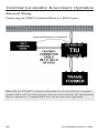
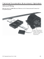
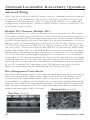
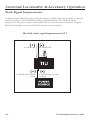
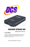
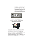
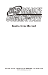
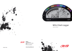
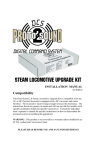
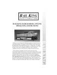
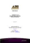
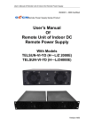
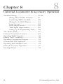
8
Chapter 8
Universal Locomotive & Accessory Operation
Advanced Wiring................................................
Wiring Thru Variable Channels..........
Connecting TMCC To DCS...............
Wiring For A Z4000 Remote.............
Large Layouts........................................
One Gauge Layouts..............................
Track Signal Improvement..................
Setting Up A Programming Track.....
ALL Mode (Track).............................................
Universal Locomotive Control.........................
Operating TMCC Engines................................
Editing TMCC Addresses.................................
Operating Conventional Engines.....................
Conventional PS2 Operation............................
Operating With Multiple Users........................
Switch & Accessory Operation........................
Smoking Whistle.................................................
98
99-106
99
100
101
102
103
104
106
107
109
110
112
113
114
115
117
118
DCS Command System User’s Guide
Universal Locomotive & Accessory Operation
Advanced Wiring
Wiring through a Variable Channel Only
In order for the TIU to function, Fixed In 1 must be connected to the transformer. If
Fixed In 1 is not required because Fixed Out 1 is not connected to any track, two additional methods are available for powering the TIU.
DCS Command System User’s Guide
99
Universal Locomotive & Accessory Operation
Advanced Wiring
Connecting the TMCC Command Base to a DCS Layout
Note: While the TIU/TMCC Connector Cable (Item No. 50-1018) looks like a standard
computer DB-9 cable, two of the pins have been reversed to allow the TIU and Command
Base to communicate. A standard DB-9 cable will not work in this application.
100
DCS Command System User’s Guide
Universal Locomotive & Accessory Operation
Advanced Wiring
Wiring with Z-4000 Remote Receiver for Conventional Control of
Fixed Channels
DCS Command System User’s Guide
101
Universal Locomotive & Accessory Operation
Advanced Wiring
One of the great features of the DCS system is that it is expandable and can be adapted
to each layout. The installation of the system to each layout may differ as the size and
complexity of the layout increase. Here are some general guidelines for installing DCS
on larger more complex layouts. Please see MTH's website, www.protosound2.com, for
more articles on layout wiring.
Multiple TIU Channels/Multiple TIUs
Depending on the size of your layout, you may need to use more than one TIU channel.
If your layout contains more than 300 feet of track and wiring or more than 5 engines on
the track at one time, MTH recommends using more than one TIU channel to maintain a
good DCS Track Signal (see System/Track Signal Test for more information). If you are
running engines in Command Mode only, remember the TIU Variable Channels can be
set to Fixed (see Menu/System/DCS Set Up) and all 4 channels of the TIU can be used
(AC power only). For layouts with more than 1200 feet of track and wire, MTH recommends using multiple TIUs set to SUPER MODE to maintain a good DCS Track Signal.
It is important to understand the DCS remote sends a command to one TIU or multiple
TIUs at the same time and the digital command for one locomotive is sent to all tracks
connected to all TIU channels simultaneously. Therefore, the train will receive the digital
command wherever it is on the layout provided that section of the layout is connected to
a powered TIU. It is also important to remember the DCS Remote can send commands
to one TIU or multiple TIUs depending on the TIU addresses you instruct the DCS
Remote to communicate with (see Menu/System/TIU Set Up/Add TIU).
Wire Management/Track Blocks
Since DCS puts the digital signal on the center rail, digital signal strength may become an
issue as the track and wire length increase. When more than one TIU channel is used,
the track should be separated into blocks. This is easily done by insulating the rails
between blocks. In addition, the wire lengths on a terminal strip should be balanced; the
length of wire should be the same wherever possible to maximize the DCS signal on the
track. Therefore, placement of the TIU and Terminal Blocks should be centralized to
minimize the wire length going to the track.
Bottom View (40-1029)
Top View (40-1029)
Remove Wire to insulate center rail.
102
DCS Command System User’s Guide
Universal Locomotive & Accessory Operation
Advanced Wiring
Conventional, Command, or Both
If you plan to run trains in conventional and command mode on the track at the same
time you will need to use a Variable channel of the TIU. Using the Variable channel of
the TIU, you can run conventional engines (vary the voltage to the track) and command
engines (send digital commands) on the track at the same time to vary the speed of the
engine for example. It is important to remember that the top speed of the command
train will be limited to the voltage on the track.
Note: The variable channels require 22 volts AC power at the Variable Input to provide the voltage displayed on the DCS Remote. If less than 22 Volts AC is provided to
the Variable Input the voltage output to the track will be less than that displayed in the
DCS Remote. The TIU Variable Channel will NOT vary DC power.
Using DC Power Supplies
It is important to remember the DCS system was designed for inside layouts. If DCS is
used outdoors on One gauge or (G gauge) layouts, please make sure the system is protected from the weather (rain and snow for example). In addition, DC power will NOT
pass through the TIU Variable Channels. Therefore, use only the Fixed 1 & 2 Channels
with DC power supplies. Also remember the polarity is critical to DCS Command operation. The positive (+) rail carries the digital signal. You may have to place the engine on
the track in the opposite direction if the engine does not have a polarity switch. It is also
very important to keep in mind the positive output (+) from the DC power supply must
be connected to the positive (+) input terminal on the TIU Fixed channel to carry the
DCS signal to the track.
DCS Command System User’s Guide
103
Universal Locomotive & Accessory Operation
Track Signal Improvements
A simple method has been discovered that improves DCS track signal quality on layouts
wired according to the MTH DCS wiring recommendations. The method can be
employed on any layout where track quality fails to exceed 8 when measured using the
DCS Track Quality test found in DCS's remote control features.
18v bulb track signal improvement # 1
to center rail
to transformer power
or red
104
to outside rail
to transformer ground
or black
DCS Command System User’s Guide
Universal Locomotive & Accessory Operation
Track Signal Improvements: (cont’d)
By attaching an 18 volt bulb to the output ports (red and black) of the TIU Output
Channels (Fixed or Variable) or onto the DCS Terminal Block input ports (red and
black), the track signal quality measurements will increase. The solution does not boost
the signal it simply cleans up signals reflected back into the TIU from the track. In effect,
the solution eliminates any "noise" caused by signals already present on the layout which
lower the effectiveness of any new signal produced by the TIU as commands are sent out.
18v bulb track signal improvement # 2
to track
TERMINAL BLOCK
(M.T.H. Item # 50-1014)
to center rail
to transformer power
or red
to outside rail
to transformer ground
or black
The solution is only effective on layouts employing the recommended DCS wiring methods as described on the Proto-Sound web site (www.protosound2.com) or in the DCS
Operator's Manual.
DCS Command System User’s Guide
105
Universal Locomotive & Accessory Operation
Advanced Wiring
Setting up a Programming Track
106
DCS Command System User’s Guide
Universal Locomotive & Accessory Operation
ALL Mode (Tracks)
ALL Mode for Tracks has been added.
You now have the ability to select either
All TIU or All Z4K tracks and have them
power on/off simultaneously.
Lashups and Record/Playback can now be
included in “All” mode operation.
1. Press the TR button
2. Select the ALL softkey
3. Select either Z4K or TIU tracks
4. Press the TSV softkey (Track Starting
Voltage). The remote will tell all the tracks
(Z4K or TIU, depending upon which one
you selected in Step 3) to go to 18V.
Similarly, you can roll the thumbwheel up
one click and you will get to 18V as well
DCS Command System User’s Guide
107
Universal Locomotive & Accessory Operation
ALL Mode (Tracks): (cont’d)
5. You can now control the voltage
applied to the tracks (Z4K or TIU-controlled) by varying the thumbwheel up or
down from 5.0-22.0 Volts.
6. When you are finished and want to shut
the tracks off you can press the TZV
(Track Zero Volts) softkey and all the
tracks you were controlling will go to zero
volts.
108
DCS Command System User’s Guide
Universal Locomotive & Accessory Operation
Universal Locomotive
Control
TMCC
1. Wire the layout with MTH’s
TIU/TMCC Connector Cable as
described in the Advanced Connection
section earlier in this chapter.
2. Add TMCC engines to the DCS
System as described in the System/Add
Engine section of the Menu chapter
above.
3. Press ENG and activate all TMCC
engines you want to run by scrolling to
them on the inactive list and pressing the
thumbwheel.
4. Select the TMCC engine you want to
control next from the active engine list by
scrolling to it and pressing the thumbwheel.
5. Use the thumbwheel as a throttle, and
move between command mode engines
(DCS or TMCC) by pressing ENG to
select engines from the active engine list.
6. All TMCC functions that have a corresponding DCS one-touch key (e.g. smoke
on/off) are controlled by that key.
7. Auxiliary TMCC functions that do not
have a corresponding one-touch key (e.g.
blow-down sounds) are controlled by a
softkey labeled with the TMCC Aux
Number.
DCS Command System User’s Guide
109
Universal Locomotive & Accessory Operation
TMCC Engine Control
DCS Version 4.0 has made a big improvement to how you operate your TMCCequipped engines. You will notice right
away the screen looks different.
1. AX1/AX2
Pressing AX1 or AX2 will highlight that
softkey.
Once one of the AX softkeys is highlighted the numeric keypad is available for
input. For example, if you wanted to play
the Steam Release sound (Aux1, button 6
on the CAB-1) you would press the AX1
softkey so it's highlighted, then press keypad button 6 on your DCS Remote. The
Steam Release sound will now play on
your TMCC engine.
If you press the AX1 or Ax2 softkey again it will disable the keypad (the AX softkey
highlighting goes away).
Below is the button sequence for changing a Train America Studios Engineer OnBoardequipped engine from 32 to 128 speed steps (select the EOB engine first from your
engine list):
· DIR AX1-AX1-AX1-AX1-AX1-keypad button #2-AX1
(You should hear the engine's horn after the 5th AX1 button press and then again after
the keypad #2 press). It's important to note that it takes two presses of the AX1 softkey
on the DCS Remote to equal one press of the AUX 1 button on the CAB-1 remote.
If you press AX1/2 so that it's highlighted but do not enter anything on the keypad within 3 seconds the DCS remote will automatically disable keypad input. Press the AX1/2
softkey twice to re-highlight it. Your numeric keypad will again be active.
110
DCS Command System User’s Guide
Universal Locomotive & Accessory Operation
TMCC Engine Control: (cont’d)
SPD
Pressing the SPD softkey enables the display to show up to 128 speed steps (0-127).
MOM
Pressing the MOM softkey allows you to
set the Momentum of an individual engine
or a lash-up.
REL
Pressing the REL softkey enables Relative
speed stepping. This is particularly useful
when operating items such as Crane Cars
that have 360 degree movement. Rolling
up on the thumbwheel is the same as spinning the knob clockwise on the CAB1/CAB-2 remote, while rolling down on
the DCS thumbwheel is the same as spinning the knob on the CAB-1/CAB-2
remote counterclockwise.
DCS Command System User’s Guide
111
Universal Locomotive & Accessory Operation
Universal Locomotive
Control
Edit TMCC Engine Address
You can change an engine’s TMCC
address via the DCS handheld.
1. Scroll through the active engine list
and when the arrow is beside the engine
you want to renumber, press the S/U
softkey (S2) to edit the address. Select
Edit Engine Address from the available
choices.
2. The LCD will prompt you to put the
switch under the engine into the PROG
position.
3. Scroll to a TMCC engine address that
is not already occupied by another TMCC
engine. Press the thumbwheel to select it.
4. The LCD will prompt you to return
the switch under the engine to the RUN
position, and the edit is complete.
112
DCS Command System User’s Guide
Universal Locomotive & Accessory Operation
Universal Locomotive
Control
Conventional Mode
1. Wire and name tracks according to the
instructions in the Advanced Connection
Section earlier in this chapter and in the
Track Setup section of the Menu chapter.
2. Place a conventional mode locomotive
on the track connected to a Variable channel of the TIU or to a Fixed channel
being controlled by a Z-4000 remote
receiver.
3. Press the “TR” (track) button, scroll to
the track you want to control, and press
the thumbwheel to select it.
4. Operate your engine according to its
conventional mode operating instructions,
using the DCS remote’s thumbwheel
instead of the transformer to adjust the
locomotive’s speed.
DCS Tip: To program Proto-Sound 1 engines, select the MPG softkey (S5). Scroll
through the list of programming options and press the thumbwheel to select the
option you want. The DCS system will send the power variations needed to activate
the option, and the engine will respond with the appropriate clinks and clanks.
To set a starting minimum voltage and maximum voltage for tracks connected to the
Variable channels, select the softkey under MTV and scroll to select the starting and
maximum voltages.
DCS Command System User’s Guide
113
Universal Locomotive & Accessory Operation
Universal Locomotive
Control
Proto-Sound 2.0 Engines in
Conventional Mode
Because the DCS remote control defaults
to command mode settings, you must tell
it when you want it to control a ProtoSound 2.0 locomotive in conventional
mode. Follow the steps below to operate
a conventional mode engine via the DCS
handheld.
1. Wire and name tracks according to the
previous instructions in the Track Setup
section of the Menu chapter.
2. Place a conventional mode locomotive
on the track connected to a Variable channel of the TIU or to a Fixed channel
being controlled by a Z-4000 remote
receiver.
3. Select the Proto-Sound 2.0 engine you
want to operate in conventional mode.
4. Scroll through the softkey list until you
find “More” in the forth softkey screen.
Press the “More” key to access the
extended softkey list. Scroll and press the
thumbwheel to select the Conv Mode
function to put the engine into conventional mode (see the chart in Appendix A).
5. Follow the conventional mode operating instructions above.
6. When you are ready to control that
engine in command mode again, re-enter
the softkey list and turn conventional
mode off.
114
DCS Command System User’s Guide
Universal Locomotive & Accessory Operation
Universal Locomotive Control
Proto-Sound 2.0 Engines in Conventional Mode (cont’d)
When in Conventional Mode, the yellow Bell, white Whistle, and red Direction buttons
operate the same way on the DCS handheld that they do on other transformers and
remotes:
Horn/Whistle - To sound the whistle, firmly press the Horn/Whistle button. The whistle will sound for as long as you continue to depress the button. It will stop when you
release the button.
Bell - To sound the bell, firmly press and release the Bell button. To turn the bell off,
press and release the Bell button again. The bell will continue to ring from the time you
turn it on until you press and release the button again to turn it off.
Direction – To change the locomotive’s direction, firmly press and release the Direction
button. Most 3-rail O Gauge locomotives are designed not to go directly from forward
to reverse; they go into neutral between directions. If the train has been moving forward,
the first press of the Direction button will put the train from forward into neutral, the
second press into reverse, the third press back into neutral, and the fourth back into forward. Be sure to see your engine’s operating instructions for more detail.
Operating with Multiple Users
1. Wire the layout as described previously.
2. Each handheld must be programmed to communicate with the TIU(s) and engines it
will control at any point in the operational session. To do this:
A. Apply power to the TIUs your handheld will control, and add them to the
handheld as described in the TIU Setup section of the Menu chapter above.
You should not re-add TIUs your handheld is already programmed to control.
Be careful not to attempt to assign more than one TIU to the same TIU
address.
DCS Tip: Proto-Sound 2.0 locomotives will respond to the appropriate one-touch
buttons (e.g. front and rear coupler) and to the softkeys S1-S4.
DCS Command System User’s Guide
115
Universal Locomotive & Accessory Operation
Universal Locomotive Control
Operating with Multiple Users(cont’d)
B. Apply power to the tracks (if any) your handheld will control in conventional
mode and add them to the handheld as described in the Track Setup section of
the Menu chapter above. You should not re-add tracks your handheld is already
programmed to control.
C. Place each engine your handheld will control (that has not already been
added to your remote control) onto the track and add it to the handheld as
described in the Engine Setup section of the Menu chapter above. You should
not re-add engines your handheld is already programmed to control.
3. Once everyone who will be using the DCS system in a given operating session has
programmed the TIUs and engines (s)he will be controlling, begin operating normally.
4. If you find that you have cross-communication between some handhelds and TIUs,
renumber some of the handhelds as described in the Set Remote Addr section in the
Menu chapter above.
Note: A given TIU and engine can be programmed into more than one handheld at a
time, for control by multiple operators. But all engines do not need to be entered into
every TIU and handheld on a layout; they may be entered only into the equipment that
will be controlling them.
DCS Tip: You can program each handheld to communicate with up to five TIUs,
whether the TIUs are all on the same layout or not. For instance, if you have two TIUs
at home and three on a Club layout where you run regularly, you can program all five
TIUs into the handheld once and leave them programmed rather than re-programming
every time. Press READ whenever you change layouts so that the remote will know
which TIUs it is communicating with in a given session. Note that the more TIUs are
added to a handheld, the longer the READ process will take, as the handheld searches
for each TIU to determine whether it is there.
DCS Tip: Engines will respond to the last command given, allowing more than one
operator to control the same engines in the same session.
116
DCS Command System User’s Guide
Universal Locomotive & Accessory Operation
Switch and Accessory Operation
Using an Accessory Interface Unit (AIU—
Item No. 50-1004) turns DCS into a complete layout control system. Once you have
wired an AIU, switches, and accessories to
the DCS system, you can control them via
the DCS remote control.
1. Press the SW (for switches) or ACC (for
accessories) button.
2. Scroll until the arrow is located beside the
switch or accessory you want to control.
3. Press the appropriate softkey below the
command you want to send (softkeys
described below).
Switches:
ALL: Selects ALL switches
connected to an AIU.
See the AIU Operators Manual for complete instructions on wiring and operation.
S/U: Shortcut to the Switch Setup screen within the menu system.
Throws a switch straight.
Throws a switch curved.
Accessories:
ALL: Selects ALL accessories connected to an AIU.
S/U: Shortcut to the Accessory Setup screen within the menu system.
On: Turns the selected accessory on for continuous operation.
Off: Turns the selected accessory off.
Act: Activates the selected accessory for one-time operation.
DCS Command System User’s Guide
117
Universal Locomotive & Accessory Operation
Proto/Smoking Whistle
This feature allows you to enable a smoking whistle feature that adds more realism
to your model by blowing steam (smoke)
out of the whistle whenever the whistle
sound is activated. It works in conjunction
with the Proto-Whistle feature. Like the
Proto-Whistle feature, the Smoking
Whistle is not available on all DCSequipped engines. This feature will only
work on those engines that have the proper hardware and an actual whistle smoke
unit.
1. Select the Proto-Whistle/Smoking
Whistle-equipped engine from your DCS
remote.
2. Press the SPW softkey. It will highlight
3. Your display will change to indicate
that Proto-Whistle is active.
4. Press the FSW softkey to enable the
Smoking Whistle Feature. This softkey
will also highlight.
118
DCS Command System User’s Guide
Universal Locomotive & Accessory Operation
Proto/Smoking Whistle: (cont’d)
5. Now watch your whistle detail on your
engine as you scroll the thumbwheel up
and down. You will see that the intensity of
the smoke varies with the intensity of the
whistle sound.
6. To disable the Smoking Whistle feature
press the FSW softkey again and it will no
longer be highlighted.
Note: When Proto-Whistle is active
your regular Whistle/Horn button is
inactive. Pressing on the thumbwheel
(Select) will allow you to control the
speed of your engine. Pressing Select
again will return you to Proto-Whistle
control.
DCS Command System User’s Guide
119