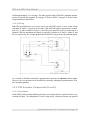
1
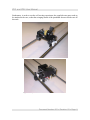
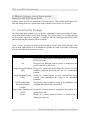
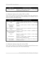
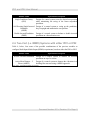
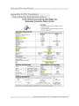
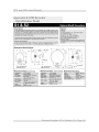
IP01 and IP02 User Manual to a potentiometer) sensing the pendulum angular position no longer constrains the range of motion of the pendulum to the inverted position. Therefore, self-erecting inverted pendulum experiments become possible. The encoder measuring the IP02 cart linear position does so through a rack-pinion system. Both encoders are typically identical. The encoder model used in the IP02 is a US Digital S1 single-ended optical shaft encoder. It offers a high resolution of 4096 counts per revolution (i.e. 1024 lines per revolution with two channels in quadrature). The complete specification sheet of the S1 optical shaft encoder is included in Appendix E. An incremental encoder gives a relative position signal. 3.2.5.2. Wiring The position signal generated by the encoder should be directly connected to a Quanser terminal board (a.k.a. I/O card) using a standard 5-pin DIN cable. DO NOT connect the encoder signal to the UPM. The internal wiring diagram of the IP02 encoder is depicted in Figure 10. The standard 5-pin DIN connector, shown in Figure 10, is also pictured as component # 10 or 11 in Figure 3. Figure 10 IP02 Encoder Wiring Document Number: 501 Revision: 03 Page: 11