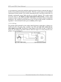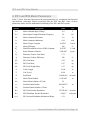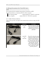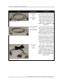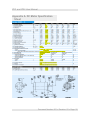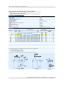
1
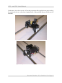
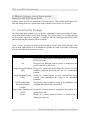
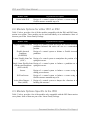
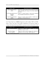
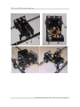
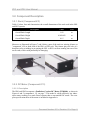
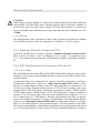
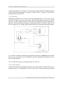
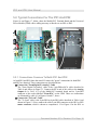
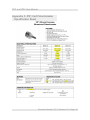
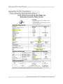
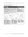
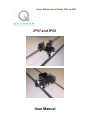
Linear Motion Servo Plants: IP01 or IP02 IP01 and IP02 User Manual IP01 and IP02 User Manual Table of Contents 1. IP01 and IP02 Presentation..................................................................................................1 1.1. General Description.....................................................................................................1 1.2. IP01 (Inverted Pendulum) Particularities.....................................................................1 1.3. IP02 (Self-Erecting Inverted Pendulum) Particularities..............................................1 2. Module Options: List of Experiments Based on the IP02 Servo Plant...............................3 2.1. Linear Family Package.................................................................................................3 2.2. Module Options for either IP01 or IP02......................................................................4 2.3. Module Options Specific to the IP02...........................................................................4 2.4. Two-Cart (i.e. MIMO) Systems with either IP01 or IP02...........................................5 3. IP01 and IP02 Component Description...............................................................................6 3.1. Component Nomenclature...........................................................................................6 3.2. Component Description...............................................................................................8 3.2.1. Rack (Component # 3).........................................................................................8 3.2.2. DC Motor (Component # 13)...............................................................................8 3.2.2.1. Description...................................................................................................8 3.2.2.2. Wiring...........................................................................................................9 3.2.3. Planetary Gearbox (Component # 14)..................................................................9 3.2.4. IP01 Potentiometers (Components # 18 and 19)..................................................9 3.2.4.1. Description...................................................................................................9 3.2.4.2. Wiring.........................................................................................................10 3.2.5. IP02 Encoders (Components # 8 and 9).............................................................10 3.2.5.1. Description.................................................................................................10 3.2.5.2. Wiring.........................................................................................................11 4. IP01 and IP02 Model Parameters......................................................................................12 5. Wiring Procedure For The IP01 And IP02........................................................................14 5.1. Cable Nomenclature...................................................................................................14 5.2. Typical Connections For The IP01 And IP02............................................................16 5.2.1. Connections Common To Both IP01 And IP02.................................................16 5.2.2. Connections Specific To The IP01.....................................................................17 5.2.3. Connections Specific To The IP02.....................................................................17 6. Testing and Troubleshooting.............................................................................................18 6.1. The IP01 or IP02 DC Motor......................................................................................18 6.1.1. Testing................................................................................................................18 6.1.2. Troubleshooting.................................................................................................18 6.2. The IP01 Potentiometers............................................................................................19 6.2.1. Testing................................................................................................................19 6.2.2. Troubleshooting.................................................................................................19 6.3. The IP02 Encoders.....................................................................................................20 6.3.1. Testing................................................................................................................20 Document Number: 501 Revision: 03 Page: i IP01 and IP02 User Manual 6.3.2. Troubleshooting.................................................................................................21 7. Obtaining Support..............................................................................................................21 Appendix A. DC Motor Specification Sheet.........................................................................22 Appendix B. Planetary Gearhead Specification Sheet..........................................................23 Appendix C. IP01 Cart Potentiometer Specification Sheet...................................................24 Appendix D. IP01 Pendulum Potentiometer Specification Sheet.........................................25 Appendix E. IP02 Encoder Specification Sheet....................................................................26 Document Number: 501 Revision: 03 Page: ii IP01 and IP02 User Manual 1. IP01 and IP02 Presentation 1.1. General Description The IP01 and IP02 are fundamental modules for the linear motion experiments. They consist of a precisely machined solid aluminum cart driven by a high quality DC motor equipped with a planetary gearbox. The cart slides along a stainless steel shaft using linear bearings. The cart is driven via a rack and pinion mechanism as opposed to belts or wheels, in order to eliminate slippage, belt stretching and other undesirable effects. This, therefore, ensures consistent and continuous traction. The following sections provide more insight into the differences between the IP01 and IP02 and their applications. 1.2. IP01 (Inverted Pendulum) Particularities A typical IP01 is depicted in Figure 1, below. In the case of the IP01, the cart position is sensed via a ten-turn potentiometer. The IP01 cart is also equipped with a rotary joint with ball bearings to which a free turning erected rod can be attached. This rod functions as an "inverted pendulum" in subsequent experiments. The angle of the rod is sensed using a conductive plastic potentiometer. However, the IP01 pendulum cannot suspend in front of the cart. Should you wish to deploy the pendulum to conduct a full 360-degree rotation the IP02 should be utilized instead. 1.3. IP02 (Self-Erecting Inverted Pendulum) Particularities A typical IP02 is depicted in Figure 2, below. The IP02 pendulum can suspend in front of the cart to perform self-erecting and gantry experiments. Consistently, the IP02 system has encoders, as opposed to potentiometers as in the IP01, to allow for multiple turns. The IP02 cart position is sensed via an quadrature incremental encoder whose shaft meshes with the track via an additional pinion. The IP02 is also equipped with a rotary joint to which a free-swinging rod can be attached and suspends in front of the cart. This rod functions, in subsequent experiments, as an "inverted pendulum", but more precisely as a self-erecting inverted pendulum as well as a regular inverted pendulum. The angle of the rod inclination about the vertical axis is also measured using a quadrature incremental encoder and is therefore unlimited and continuous over the entire range of motion. The pendulum in itself is a module and can be mounted on or remove from the cart. Document Number: 501 Revision: 03 Page: 1 IP01 and IP02 User Manual Furthermore, in order to run the self-erecting experiment, the supplied extra mass needs to be attached to the cart, so that the swinging inertia of the pendulum does not lift the cart off the track. Figure 1 IP01 System Figure 2 IP02 System Document Number: 501 Revision: 03 Page: 2 IP01 and IP02 User Manual 2. Module Options: List of Experiments Based on the IP02 Servo Plant Quanser values itself for the modularity of its experiments. This modular philosophy facilitates the change from one experimental setup to another with relative ease of work. 2.1. Linear Family Package The IP02 linear plant module serves as the base component for the linear family of experiments, also known as the Linear Family Package. The "Linear Family" is a package that has all the modules required to configure 7 completely different challenges based on the IP02 (thus maximizing the return on your investment). Table 1, below, provides a list of the modules members of the Linear Family Package. Each one of them (individually or in combination) expands the range of possible experiments based on the IP02 linear motion servo plant. Module Name Experiment Description N/A Design of a control system to manipulate the position of the IP01 or IP02 cart. N/A Design of two different control systems to manipulate the speed of the IP01 or IP02 cart. Single Inverted Pendulum Design of a control system that keeps the classical inverted (SIP) pendulum balanced and tracks the cart to a commanded position. Single Pendulum Gantry (SPG) Design of a control system to track a desired cart linear position while minimizing the swing of the suspended pendulum. Self-Erecting Single Inverted Pendulum (SESIP) Design of a control system to swing up the pendulum, keep it upright and maintain the cart position. Single Linear Flexible Joint Design of a control system to manipulate the position of a (SLFJ) spring driven cart. Seesaw Design of a control system to balance a seesaw using a sliding powered mass. Document Number: 501 Revision: 03 Page: 3 IP01 and IP02 User Manual Module Name Experiment Description Seesaw with SLFJ Design of a control system to balance a seesaw using a flexible structure mounted atop of it. Table 1 Modules of the Linear Family Package 2.2. Module Options for either IP01 or IP02 Table 2, below, provides a list of all the modules compatible with the IP01 and IP02 linear motion servo plants. These modules can be used individually or in combination. Some of them are part of the Linear Family Package. Module Name Experiment Description Single Inverted Pendulum Design of a control system that keeps the classical inverted (SIP) pendulum balanced and tracks the cart to a commanded position. Flexible Inverted Pendulum (FLEXPEN) Design of a control system to balance a flexible inverted pendulum. Linear Flexible Joint Cart Design of a control system to manipulate the position of a (LFJC) spring driven cart. Single Linear Flexible Joint Design of a control system to balance a pendulum on a with Inverted Pendulum spring driven cart. (SLFJ with IP) Seesaw Design of a control system to balance a seesaw using a sliding powered mass. SLFJ on Seesaw Design of a control system to balance a seesaw using a flexible structure mounted atop of it. Active Mass Damper – 1 Floor (AMD) Design of a control system to dampen the vibrations in a building-like structure. Table 2 IP01- and IP02-Based List of Modules 2.3. Module Options Specific to the IP02 Table 3, below, provides a list of the modules only compatible with the IP02 linear motion servo plants. Some of them are part of the Linear Family Package. Document Number: 501 Revision: 03 Page: 4 IP01 and IP02 User Manual Module Name Experiment Description Single Pendulum Gantry (SPG) Design of a control system to track a desired cart position while minimizing the swing of the linear suspended pendulum. Self-Erecting Single Inverted Design of a control system to swing up the pendulum, Pendulum keep it upright and maintain the cart position. (SESIP) Double Inverted Pendulum (DBIP) Design of a control system to balance a double inverted pendulum on a linear motion cart. Table 3 IP02-Based Modules 2.4. Two-Cart (i.e. MIMO) Systems with either IP01 or IP02 Table 4, below, lists some of the possible combinations of the previous modules to configure Multi-Input-Multi-Ouput (MIMO) experiments, based on either the IP01 or IP02. Module Name Experiment Description Seesaw / Inverted Pendulum Design of a control system to balance an inverted pendulum on top of a seesaw. Active Mass Damper – 2 Floors (AMD-2) Design of a control system to dampen the vibrations in a building-like structure using a MIMO approach. Table 4 IP01- or IP02-Based MIMO Experiments Document Number: 501 Revision: 03 Page: 5 IP01 and IP02 User Manual 3. IP01 and IP02 Component Description 3.1. Component Nomenclature As a quick nomenclature, Table 5, below, provides a list of all the principal elements composing the IP01 and IP02 systems. Every element is located and identified, through a unique identification (ID) number, on the IP01 and/or IP02 systems represented in Figures 3, 4, 5, and 6, below, as well as Figures 7 and 8. ID # Description ID # Description 1 IP02 Cart 2 Stainless Steel Shaft 3 Rack 4 Cart Position Pinion 5 Cart Motor Pinion 6 Cart Motor Pinion Shaft 7 Pendulum Axis 8 IP02 Cart Encoder 9 IP02 Pendulum Encoder 10 IP02 Cart Encoder Connector 11 IP02 Pendulum Encoder Connector 12 Motor Connector 13 DC Motor 14 Planetary Gearbox 15 Linear Bearing 16 Pendulum Socket 17 IP02 Weight 18 IP01 Cart Potentiometer 19 IP01 Pendulum Potentiometer 20 IP01 Cart 21 S1 & S2 Connector 22 Rack End Plate 23 Rack Set Screw: (7/64)" 24 Track Discontinuity Table 5 IP01 and IP02 Component Nomenclature Document Number: 501 Revision: 03 Page: 6 IP01 and IP02 User Manual Figure 3 IP02: Front View Figure 5 IP02 with Weight: Front View Figure 4 IP02: Bottom View Figure 6 IP01: Front View Document Number: 501 Revision: 03 Page: 7 IP01 and IP02 User Manual 3.2. Component Description 3.2.1. Rack (Component # 3) Table 6, below, lists and characterizes the overall dimensions of the rack used in the IP01 and IP02 systems: Description Value Unit Overall Rack Length 1.02 m Overall Rack Height 6.10E-002 m Overall Rack Depth 0.15 m Table 6 IP01 and IP02 Rack Overall Dimensions Moreover as illustrated in Figures 7 and 8 below, parts of the track are missing (feature or "component" #24) at both ends of the IP01 or IP02 rack. This feature plays the role of a hardware safety watchdog in preventing the IP01 or IP02 cart from running into one of the track's ends, which could potentially be damaging. Figure 7 Rack Left End Figure 8 Rack Right End 3.2.2. DC Motor (Component # 13) 3.2.2.1. Description The IP01 and IP02 incorporate a Faulhaber Coreless DC Motor (2338S006), as shown in Figures 4 and 5 (component # 13), on page 7. This model is a high efficiency low inductance motor resulting in a much faster response than a conventional DC motor. The complete specification sheet of the motor is included in Appendix A. Document Number: 501 Revision: 03 Page: 8 IP01 and IP02 User Manual CAUTION: High Frequency signals applied to a motor will eventually damage the gearbox and/or the motor brushes. The most likely source for high frequency noise is derivative feedback. If the derivative gain is too high, a noisy voltage will be fed into the motor. To protect your motor, you should always band limit your signal (especially derivative feedback) to a value of 50Hz. 3.2.2.2. Wiring The supplied motor cable is designed to connect from a Quanser Universal Power Module to a 4-pin DIN connector, shown as component # 12 in Figures 3, 4, and 6, on page 7. 3.2.3. Planetary Gearbox (Component # 14) In the IP01 and IP02, the DC motor is coupled to a Faulhaber Planetary Gearhead Series 23/1, as shown in Figures 4 and 5 (component # 14), on page 7. Its reduction ratio is 3.71:1. The complete specification sheet of the planetary gearbox is included in Appendix B. 3.2.4. IP01 Potentiometers (Components # 18 and 19) 3.2.4.1. Description The main difference between the IP01 and the IP02 is that the IP01 makes use of two potentiometers to sense both cart and pendulum positions, as opposed to the IP02 which uses two encoders instead. As depicted in Figure 6 by component # 18, on page 7, the IP01 cart position is sensed by a 10-turn black potentiometer, namely the Vishay Spectrol model 534-1-1-103. As illustrated by its wiring diagram in Figure 9, the IP01 cart potentiometer is connected to a ±12 Volt DC power supply through two bias resistors of 7.15 kΩ each. According to the wiring diagram Figure 9 and under normal operations, potentiometer terminal 1 should measure +5VDC while terminal 3 should measure -5VDC. The actual position voltage is available at terminal 2. The total output range of the cart position potentiometer results to be ±5V over its 10 complete turns (i.e. 3600 degrees). The main specifications of the IP01 cart potentiometer are included in Appendix C, on page 24. Regarding the inverted pendulum potentiometer, it is a Vishay Spectrol model 138-0-0-103. It is represented in Figure 6 by component # 19. Its wiring diagram is also depicted in Figure 9. No bias resistor is used. On the IP01, the inverted pendulum is mechanically constrained to the upright position and limited to a ±32º-deviation from the vertical, during which the pendulum potentiometer output is Document Number: 501 Revision: 03 Page: 9 IP01 and IP02 User Manual within approximately a 5-volt range. The main specifications of the IP01 pendulum potentiometer are included in Appendix D, on page 25. Refer to Table 7, on page 13, for the resulting potentiometer sensitivities. 3.2.4.2. Wiring Both IP01 potentiometers are wired to one 6-pin mini DIN socket, as seen in the wiring schematic in Figure 9. A picture of the same 6-pin mini DIN socket, represented as component # 21, is also available in Figure 6. Once the 6-pin mini DIN socket is connected to a Quanser UPM, the potentiometer signals are typically available on S1 and S2, where S1 and S2 are, respectively, the voltages proportional to the IP01 cart position and pendulum angle. Figure 9 IP01 Wiring of the Two Potentiometers As a remark, it should be noted that a potentiometer measures an absolute position signal. However, the zero position can be modified by manually adjusting the potentiometer "neutral" mounting position. 3.2.5. IP02 Encoders (Components # 8 and 9) 3.2.5.1. Description On the IP02, both cart and pendulum positions are measured with two optical encoders, represented in Figure 3 by components # 8 and 9, respectively. Having an encoder (as opposed Document Number: 501 Revision: 03 Page: 10 IP01 and IP02 User Manual to a potentiometer) sensing the pendulum angular position no longer constrains the range of motion of the pendulum to the inverted position. Therefore, self-erecting inverted pendulum experiments become possible. The encoder measuring the IP02 cart linear position does so through a rack-pinion system. Both encoders are typically identical. The encoder model used in the IP02 is a US Digital S1 single-ended optical shaft encoder. It offers a high resolution of 4096 counts per revolution (i.e. 1024 lines per revolution with two channels in quadrature). The complete specification sheet of the S1 optical shaft encoder is included in Appendix E. An incremental encoder gives a relative position signal. 3.2.5.2. Wiring The position signal generated by the encoder should be directly connected to a Quanser terminal board (a.k.a. I/O card) using a standard 5-pin DIN cable. DO NOT connect the encoder signal to the UPM. The internal wiring diagram of the IP02 encoder is depicted in Figure 10. The standard 5-pin DIN connector, shown in Figure 10, is also pictured as component # 10 or 11 in Figure 3. Figure 10 IP02 Encoder Wiring Document Number: 501 Revision: 03 Page: 11 IP01 and IP02 User Manual 4. IP01 and IP02 Model Parameters Table 7, below, lists and characterizes the main parameters (e.g. mechanical and electrical specifications, convertion factors) associated with the IP01 and IP02. Some of these parameters can be used for mathematical modelling of the IP01 and IP02 systems. Symbol Description Value Unit Vnom Motor Nominal Input Voltage 6.0 V fvmax Motor Input Voltage Maximum Frequency 50 Hz Rm Motor Armature Resistance 2.6 Ω Lm Motor Armature Inductance 0.18 mH Kt Motor Torque Constant 0.00767 N.m/A ηm Motor Efficiency 100 % Km Back-ElectroMotive-Force (EMF) Constant 0.00767 V.s/rad Jm Rotor Moment of Inertia 3.90E-007 kg.m2 Kg Planetary Gearbox Gear Ratio 3.71 ηg Planetary Gearbox Efficiency 100 % Mc1 IP01 Cart Mass 0.52 kg Mc2 IP02 Cart Mass 0.57 kg Mw IP02 Cart Weight Mass 0.37 kg Lt Track Length 0.990 m Tc Cart Travel 0.814 m Pr Rack Pitch 1.664E-003 m/tooth rmp Motor Pinion Radius 6.35E-003 m Nmp Motor Pinion Number of Teeth rpp Position Pinion Radius Npp Position Pinion Number of Teeth KEC IP02 Cart Encoder Resolution KEP IP02 Pendulum Encoder Resolution αrange IP01 Inverted Pendulum Mechanical Range 24 0.01482975 m 56 2.275E-005 m/count 0.0015 rad/count ±32º º Document Number: 501 Revision: 03 Page: 12 IP01 and IP02 User Manual Symbol Description Value Unit KPC IP01 Cart Potentiometer Sensitivity 0.0931 m/V KPP IP01 Pendulum Potentiometer Sensitivity -0.2482 rad/V Table 7 IP01 and IP02 System Paremeters Document Number: 501 Revision: 03 Page: 13 IP01 and IP02 User Manual 5. Wiring Procedure For The IP01 And IP02 This section describes the standard wiring procedure for both IP01 and IP02. The following hardware, accompanying the IP01 or IP02, is assumed: Data Acquisition Board: Power Amplifier: Quanser MultiQ-PCI / MultiQ-3 or equivalent. Quanser UPM 1503 / UPM 2405 or equivalent. 5.1. Cable Nomenclature Table 8, below, provides a description of the standard cables used in the wiring of the IP01 and IP02. Cable Designation Description 5-pin-DIN to RCA This cable connects an analog output of the data acquisition terminal board to the power module for proper power amplification. 4-pin-DIN to 6-pin-DIN This cable connects the output of the power module, after amplification, to the desired actuator (i.e. IP01 or IP02 motor). One end of this cable contains a resistor that sets the amplification gain. The cable gains currently available are: 1, 3, or 5. Every cable carries a label, at both ends, with its particular gain on it. Figure 11 "From Digital-To-Analog" Cable Figure 12 "To Load" Cable Document Number: 501 Revision: 03 Page: 14 IP01 and IP02 User Manual Cable Designation Description 5-pin-stereoDIN to 5-pin-stereoDIN This cable is specific to the IP02 system. It carries the encoder signals between an encoder connector and the data acquisition board (to the encoder counter). Namely, these signals are: +5VDC power supply, ground, channel A, and channel B. 6-pin-mini-DIN to 6-pin-mini-DIN This cable is specific to the IP01 system. It carries analog signals between one or two plant sensors and the UPM, where the signals can be either monitored and/or used by an analog controller. For example, connected to the IP01, the cable provides a ±12VDC bias to the two potentiometers and carries the two wiper voltages to S1 and S2 on the UPM. 5-pin-DIN to 4xRCA This cable is needed by the IP01 system. It carries the analog signals, previously taken from the plant sensors, unchanged, from the UPM to the Digital-To-Analog input channels on the data acquisition terminal board. Figure 13 "Encoder" Cable Figure 14 "From Analog Sensors" Cable Figure 15 "To Analog-To-Digital" Cable Table 8 Cable Nomenclature Document Number: 501 Revision: 03 Page: 15 IP01 and IP02 User Manual 5.2. Typical Connections For The IP01 And IP02 Figure 16 and Figure 17, below, show the MultiQ-PCI Terminal Board and the Universal Power Module (UPM) with a cabling necesary to interface to an IP01 or IP02. Figure 16 MultiQ-PCI Terminal Board Figure 17 Universal Power Module (UPM) 5.2.1. Connections Common To Both IP01 And IP02 As both IP01 and IP02 share the same DC motor, the "power" connections for both IP01 and IP02 are identical. These connections are described below: Connect the "From Digital-To-Analog" Cable The "From Digital-To-Analog" cable is the 5-pin-DIN-to-RCA cable described in Table 8 and shown in Figure 11. Connect the RCA end of this cable to the Analog Output 0 (i.e. DAC # 0) of the MultiQ-PCI terminal board and its 5-pin-DIN connector to the socket labelled "From D/A" on the UPM. These two connections are illustrated by cable # 1 in Figures 16 and 17, above. Connect the "To Load" Cable The "To Load" cable is the 4-pin-DIN-to-6-pin-DIN cable described in Table 8 and shown in Figure 12. First, connect the cable 4-pin-DIN connector to the IP01 or IP02 motor connector, which is shown as component # 12 in Figure 6 for the IP01 or Document Number: 501 Revision: 03 Page: 16 IP01 and IP02 User Manual Figure 3 for the IP02. Then connect the cable 6-pin-DIN connector to the UPM socket labelled "To Load". The connection to the UPM is illustrated by cable # 2 in Figure 17, above. 5.2.2. Connections Specific To The IP01 In the case of the IP01, the two potentiometers have to be connected. To do so, follow the two steps described below: Connect the "From Analog Sensors" Cable The "From Analog Sensors" cable is the 6-pin-mini-DIN-to-6-pin-mini-DIN cable described in Table 8 and shown in Figure 14. First connect one end of the cable to the IP01 S1 & S2 Connector, which is shown as component # 21 in Figure 6. Then connect its other end to the UPM socket labelled "S1 & S2", which is contained inside the UPM "From Analog Sensors" front panel. The connection to the UPM is illustrated by cable # 4 in Figure 17, above. Connect the "To Analog-To-Digital" Cable The "To Analog-To-Digital" cable is the 5-pin-DIN-to-4xRCA cable described in Table 8 and shown in Figure 15. First, connect the cable 5-pin-DIN connector to the UPM socket labelled "To A/D", as illustrated by cable # 3 in Figure 17, above. The other end of the cable is split into four RCA connectors, each one labelled with a single digit ranging from one to four. This numbering corresponds to the four possible analog sensor signals passing through the UPM, namely S1, S2, S3 and S4. In order for the analog signals to be used in software, you should then connect all four RCA connectors to the first four analog input channels of your MultiQ terminal board. Specifically, connect S1 to Analog Input 0, S2 to Analog Input 1, S3 to Analog Input 2, and S4 to Analog Input 3, as illustrated by cable #3 in Figure 16, above. 5.2.3. Connections Specific To The IP02 In the case of the IP02, the two encoders have to be connected. To do so, follow the two steps described below: Connect the Cart Position "Encoder" Cable The "Encoder" cable is the 5-pin-stereo-DIN-to-5-pin-stereo-DIN cable described in Table 8 and shown in Figure 13. First connect one end of the cable to the IP02 Cart Encoder Connector, which is shown as component # 10 in Figure 3. Then connect the other cable end to the Encoder Input 0 on your MultiQ terminal board, just as illustrated by cable # 5 in Figure 16, above. Connect the Pendulum Angle "Encoder" Cable The "Encoder" cable is the 5-pin-stereo-DIN-to-5-pin-stereo-DIN cable described in Table 8 and shown in Figure 13. First connect one end of the cable to the IP02 Pendulum Encoder Connector, which is shown as component # 11 in Figure 3. Document Number: 501 Revision: 03 Page: 17 IP01 and IP02 User Manual Then connect the other cable end to the Encoder Input 1 on your MultiQ terminal board, just as illustrated by cable # 6 in Figure 16, above. CAUTION: Any encoder should be directly connected to the Quanser terminal board (or equivalent) using a standard 5-pin DIN cable. DO NOT connect the encoder cable to the UPM! 6. Testing and Troubleshooting The present section, and following subsections, describe some basic functional tests to determine if your IP01 or IP02 is operating normally. It is assumed that the IP01 or IP02 have been entirely connected as described in Section Wiring Procedure For The IP01 And IP02, above. To carry out the testing (and troubleshooting, if necessary) described hereafter, you should be able to create and use a "controller" that can measure and apply desired signals. You can do so very conveniently in software by using the WinCon and Simulink implementation, or SimuLinuxRT, or LabView, or equivalent. Alternatively, the IP01 or IP02 testing can also be achieved by using a signal generator and an oscilloscope. To learn how to interface and use your IP01 or IP02 with WinCon, please refer to the manual titled IP01 or IP02 / WinCon Integration. 6.1. The IP01 or IP02 DC Motor 6.1.1. Testing Apply a small voltage (e.g. around 1V) to analog output channel 0 of the MultiQ terminal board, using, for example, WinCon and Simulink. A positive voltage should result in a motion of the cart to the right, when facing the IP01 or IP02 (i.e. when facing the position and motor pinions in front of the cart, with the cables connected to the back of the cart). Likewise a negative voltage should result in a motion of the cart to the left part of the track, when facing the IP01 or IP02. 6.1.2. Troubleshooting If the motor is not responding to any signals applied, you should: check that the power amplifier (e.g. UPM) is functional (e.g. is the power switched on?). check that the MultiQ is functional, i.e. the desired voltage is being generated. The red LED (i.e. Light Emitting Diode) on the board should be on. If it is not, the fuse may be burnt and need replacement. Document Number: 501 Revision: 03 Page: 18 IP01 and IP02 User Manual check that the voltage is actually reaching the motor terminals (use a voltmeter or an oscilloscope). If the motor terminals are receiving the signal and the motor is still not turning, your motor might be damaged and will need to be repaired. Please refer to Section Obtaining Support on page 21 for information on contacting Quanser for technical support. 6.2. The IP01 Potentiometers 6.2.1. Testing Assuming that all the connections in relation to the IP01 have been made as described in Section Wiring Procedure For The IP01 And IP02, on page 14, you should be able to measure and monitor the two IP01 potentiometer signals (i.e. S1 and S2). Using, for example, WinCon and Simulink, the two potentiometer voltages can be traced on WinCon Scopes and/or displayed on WinCon Digital Meters. On the MultiQ terminal board, the cart position potentiometer voltage (i.e. S1) is available on the analog input channel 0 and the pendulum angle potentiometer voltage (i.e. S2) on the analog input channel 1. Pushing manually the IP01 cart to the right side of the track, when facing it, should result in a positive change in the cart position potentiometer voltage, which should gradually increase up to +5V. Likewise, pushing the IP01 cart towards the left side of the track, when facing it, should result in a negative change in the cart position potentiometer voltage, which should gradually decrease down to -5V. Combining this with the observations made in Section The IP01 or IP02 DC Motor, on page 18, it is seen that a positive motor voltage results in an increasing cart position potentiometer voltage, and vice-versa. On a similar manner, rotating manually the inverted pendulum (or pendulum socket) clockwise (CW), when facing the cart, should result in a positive change in the pendulum potentiometer voltage, gradually increasing to +2.5V. Likewise, rotating the inverted pendulum counter-clockwise (CCW), when facing the cart, should result in a negative change in the pendulum potentiometer voltage, gradually decreasing to -2.5V. 6.2.2. Troubleshooting If one of the potentiometers does not measure correctly, you should: check that the MultiQ is functional. The red LED on the board should be on. If it is not, the fuse may be burnt and need replacement. To check the analog-to-digital conversion from the analog input channel that you are using on the MultiQ, you could run the analog loopback example provided in the WinCon User's Guide manual. check that the power amplifier (e.g. UPM) is functional. The power to the UPM needs to be switched on in order for it to supply both potentiometers with ±12VDC. Document Number: 501 Revision: 03 Page: 19 IP01 and IP02 User Manual measure the voltage across the potentiometer. Prior to doing that, ensure that the potentiometer is powered with ±12VDC at the 6-pin-mini-DIN connector, as shown in Figure 9. You should observe ±5VDC at the cart position potentiometer terminals, and ±12VDC at the pendulum potentiometer terminals. Moreover, if the voltage from the wiper does not change when you rotate the potentiometer shaft (measuring with, for example, a voltmeter or an oscilloscope), your potentiometer may need to be replaced. To obtain technical assistance, please refer to Section Obtaining Support on page 21 for information on contacting Quanser. 6.3. The IP02 Encoders 6.3.1. Testing Assuming that all the connections in relation to the IP02 have been made as described in Section Wiring Procedure For The IP01 And IP02, on page 14, you should be able to measure and monitor the two IP02 encoder signals. For example, with WinCon and Simulink, the two encoder counters can be read by the Encoder Input block, corresponding to your MultiQ, and traced on WinCon Scopes and/or displayed on WinCon Digital Meters. On the MultiQ terminal board, the cart encoder signal is available on the encoder input channel 0 and the pendulum encoder signal on the encoder input channel 1. Moving the IP02 cart, when facing it, to the right side of the track should result in a positive change (i.e. increase) in the cart position encoder counts, which should increase at a rate of +4096 counts per revolution of the position pinion. Likewise, moving the IP02 cart, when facing it, towards the left side of the track should result in a negative change in the cart position (i.e. decrease) in the cart position encoder counts, which should decrease at a rate of -4096 counts per revolution of the position pinion. Combining this with the observations made in Section The IP01 or IP02 DC Motor, on page 18, it is seen that a positive motor voltage results in increasing cart position encoder counts, and vice-versa. Similarly, rotating the IP02 free-falling pendulum (or pendulum socket) counter-clockwise (CCW), when facing the cart, should result in a positive change in the pendulum encoder counts, which should increase at a rate of +4096 counts per pendulum revolution. Likewise, rotating the free-falling pendulum clockwise (CW), when facing the cart, should result in a negative change in the pendulum encoder counts, which should decrease at a rate of -4096 counts per pendulum revolution. Notes: You should keep in mind that some data acquisition systems do not measure in quadrature, in which case you will receive a quarter of the expected counts, resulting to a lesser resolution. Other data acquisition systems do measure in quadrature but increment the count by Document Number: 501 Revision: 03 Page: 20 IP01 and IP02 User Manual 0.25 (as opposed to having integer number of counts). Therefore, you should know how the system you are using operates. All Quanser counters measure a total of four times the number of encoder lines per rotation. Therefore a 1024-line encoder results in 4096 integer number of counts for every full revolution. 6.3.2. Troubleshooting If one of the encoders does not measure correctly, you should: check that the MultiQ is functional. The red LED on the board should be lit. If it is not, the fuse may be burnt and need replacement. check that both signals from the encoder channels A and B are properly generated and fed to the MultiQ. Using an oscilloscope, you should observe two square waves, representing channels A and B, with a phase shift of 90ºe (between the rising edge of the two channels). If you believe that your encoder is damaged and need to be replaced, refer to Section Obtaining Support, below, for information on contacting Quanser for technical support. 7. Obtaining Support Note that a support contract may be required to obtain technical support. To obtain support from Quanser, go to http://www.quanser.com and click on the Tech Support link. Fill in the form with all requested software version and hardware information and a description of the problem encountered. Submit the form. Be sure to include your email address and a telephone number where you can be reached. A qualified technical support person will contact you. Document Number: 501 Revision: 03 Page: 21 IP01 and IP02 User Manual Appendix A. DC Motor Specification Sheet Document Number: 501 Revision: 03 Page: 22 IP01 and IP02 User Manual Appendix B. Planetary Gearhead Specification Sheet Document Number: 501 Revision: 03 Page: 23 IP01 and IP02 User Manual Appendix C. IP01 Cart Potentiometer Specification Sheet Document Number: 501 Revision: 03 Page: 24 IP01 and IP02 User Manual Appendix D. IP01 Pendulum Potentiometer Specification Sheet Document Number: 501 Revision: 03 Page: 25 IP01 and IP02 User Manual Appendix E. IP02 Encoder Specification Sheet Document Number: 501 Revision: 03 Page: 26