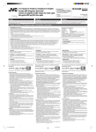
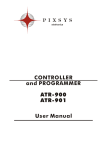
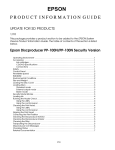
1
ATR 902 Controller User manual - Summary 1 Safety guide lines ................................................................................................................................10 2 Model identification ...........................................................................................................................10 3 Technical data ......................................................................................................................................11 3.1 General features.........................................................................................................................11 3.2 Hardware features.....................................................................................................................11 3.3 Software features ......................................................................................................................11 4 Size and Installation ...........................................................................................................................12 5 Electrical wirings .................................................................................................................................13 5.1 Wiring diagram ..........................................................................................................................13 6 Displays and keys function ...............................................................................................................13 6.1 Numeric indicators (Display) ..................................................................................................14 6.2 Meaning of Status Lights (Led) ..............................................................................................14 6.3 Keys .............................................................................................................................................15 7 Programming and configuration ...................................................................................................16 7.1 Programming (or modifying) cycle data.............................................................................16 7.1.1 Programming of starting setpoint (if not configured, see par. 6.1.2) ...............16 7.1.2 Programming of the step (segment) .........................................................................17 7.1.3 Programming of the alarm/auxiliary (if configured) ...........................................17 7.1.4 End programming .........................................................................................................17 8 Cycle start 18 8.1 Start of a cycle and setting of delayed start .......................................................................18 8.2 Fast advancement function ...................................................................................................18 8.3 Simple controller function ......................................................................................................19 9 Programmer functions ......................................................................................................................20 9.1 Hold function ..............................................................................................................................20 9.2 Automatic Tuning......................................................................................................................20 9.3 Manual Tuning ...........................................................................................................................20 9.4 Recovery of interrupted cycle .................................................................................................21 9.4.1 Recovery with automatic gradient............................................................................21 9.4.2 Recovery with recovery gradient ...............................................................................22 9.5 Waiting step end ........................................................................................................................22 9.6 Loading default values ............................................................................................................23 10 Configuration for installer ................................................................................................................23 11 Table of confi guration parameters................................................................................................24 11.1 1st level parameters ..................................................................................................................24 11.2 2nd level parameters (for expert operators) ......................................................................29 12 Alarm intervention modes................................................................................................................31 13 Table of Anomaly Signals..................................................................................................................33 14 Summary of configuration parameters ........................................................................................34 14.1 1st level parameters ..................................................................................................................34 14.2 2nd level parameters ................................................................................................................35 Introduction Thanks for choosing a Pixsys device. The plug-in controller ATR902 is specially dedicated to applications in the glass, metal and pottery industry. This controller provides high accuracy of the programmed firing cycle and reliable monitoring of the temperature. It can store up to 15 completely configurable programs, each consisting of max. 18 segments. The first 5 cycles can be associated to a mnemonic name (see parameters 48-52). Delayed start is also available as well as other software functions. A relay output can be configured as alarm. All parameters are protected by a password to avoid unauthorized access. 1 Safety guide lines Read carefully the safety guidelines and programming instructions contained in this manual before using/connecting the device. Disconnect power supply before proceeding to hardware settings or electrical wirings. Only qualified personnel should be allowed to use the device and/or service it and in accordance to technical data and environmental conditions listed in this manual. Do not dispose electric tools together with household waste material. In observance European Directive 2002/96/EC on waste electrical and electronic equipment and its implementation in accordance with national law, electric tools that have reached the end of their life must be collected separately and returned to an environmentally compatible recycling facility. 2 Model identification The ATR902 series includes only one version which is described into the following table: Power supply 230 Vac ±15% 50/60Hz – 3VA ATR902-12ABC 1 sensor input + 2 relays 1A 10 ATR902 - User manual 3 Technical data 3.1 General features Display Operating temperature Sealing Material Weight 4 display 0,50’’ - 4 display 0,30’’ - 12 red led 0-45°C, humidity 35..95uR% IP54 on front panel Shock-resistant polystyrene Approx. 400 g 3.2 Hardware features Sensor input Relay outputs AI1 - Configurable for Thermocouple K,S,R,J,T,E,N. Cold junction automatic compensation 0 ... 50°C. 2 Relays configurable as control output and alarm relay (safety or auxiliary) Accuracy (25°C) +/-0.2 % ± 1 digit (full scale). Cold junction accuracy 0.1°C/°C Contacts: 1A-250V~ for resistive charges 3.3 Software features Regulation Algorythm Proportional band Integral time ON-OFF with hysteresis. P, PI, PID, PD proportional time. 0...9999°C or °F 0,0...999,9 sec (0 excludes integral function) Derivative time 0,0...999,9 sec (0 excludes derivative function) Controller functions Programmable cycles Manual or automatic tuning, selectable alarms, Interruped cycle recovery, Waiting, Delayed start 15 (max 18 steps each) + function “simple controller” with programmable setpoint ATR902 - User manual 11 4 Size and Installation Optional: support for panel-mounting Cod. 1300.20.043 12 ATR902 - User manual 5 Electrical wirings Please notice the following safety guidelines: • Separate control lines from the power wires. • Avoid the proximity of remote control switches, electromagnetic meters, powerful engines. • Avoid the proximity of power groups, especially those with phase control. 5.1 Wiring diagram 1_ Neutral 2_ Neutral 3_ Thermocouple + 4_ Thermocouple 5_ Power supply (phase) 6_ Control output (phase) 7_ Aux output (phase) 8_ Not Connected Optional: multipolar connector (Cod. 0400.70.001). 6 Displays and keys function 1 2 4 3 7 5 10 11 8 9 14 12 16 13 17 15 ATR902 - User manual 13 6.1 Numeric indicators (Display) 1 2 Usually visualizes mesured temperature, it may visualize also (programmed temperature) setpoint value, time elapsed from cycle start, number of operating step or the percentage value of the command output. During confi guration it visualizes the value of entering parameter. Visualization can be customized with setpoint, time elapsed from cycle start or number of operating step. During configuration it visualizes the value of entering parameter. 6.2 Meaning of Status Lights (Led) 3 4 5 C1 7 RUN A1 TUN ON when the heating elements are activaved. ON when alarm 1 is active. ON when controller is executing an auto-tuning cycle. ON when the device is in START cycle or in “Simple controller” mode. 8 ON when the programmer is executing a rising step. 9 ON when the programmer is executing a maintenance step. 10 ON when the programmer is executing a falling step. 11 14 ATR902 - User manual Cycle progress. Flashing Led shows the step being executed; Fixed Led shows the step already done. 6.3 Keys 12 13 14 STEP 15 CYCLE 16 START STOP 17 ON OFF • In configuration allows to scroll and modify parameters • Scroll cycles to be started or modified. • In cycle programming allows to modify time and setpoint values. • Modifies the setpoint during “simple controller” function ( ). • Allows a fast advancement of the cycle when it is in “START”. • In configuration allows to scroll and modify parameters. • Scroll cycles to be started or modified. • In cycle programming allows to modify time and setpoint values. • Modifies the setpoint during “simple controller” function ( ). • Allows a fast retrograde of the cycle when it is in “START”. • With controller in STOP allows to visualizes the duration of the last cycle (if chronometer is enabled). • In programming allows to confirm a value and move to the next one. • With controller in START allows to visualize cyclically the setpoint and the other process value. • With controller in STOP allows to select cycles to start or modify and to enter parameters configuration. • In configuration allows to modify the selected parameter and to confirm the entered value. • During a cycle, to activate/deactivate HOLD function, press for 1 second. • In configuration allows to visualize the selected parameter in mnemonic or numeric way. • Starts a new cycle or Stops the one which is being execute. • Operates as exit key (ESCAPE) during cycles or parameters configuration. • Switches the controller OFF (standby) and ON. ATR902 - User manual 15 7 Programming and configuration There are two programming levels: 1. Cycles programming (for operator/user), to enter time/setpoint values for each step of cycle. 2. Configuration (for manufacturer/installer of plant), to enter main parameters (sensor type, output type, intervention type alarm/auxiliary ext.). 7.1 Programming (or modifying) cycle data • With or without starting setpoint • With or without timed auxiliary outputs1 When controller is in follow the points below. Press 1 CYCLE Display Red display visualizes Do At each pression selects the next cycle ( for cycle no.2 up to for cycle 15). 7.1.1 Programming of starting setpoint (if not configured, see par. 6.1.2) The selection of an initial setpoint (a specific starting temperature of the cycle) grants the correct gradient if the kiln is still heat from a previous process. Press 2 3 1 STEP Display Do Red display visualizes *. Green display shows the “starting setpoint”. Otherwise pass to point 4. At any time press programming. Increases, decreases value on green display. Select starting setpoint (starting temperature). START STOP to exit This section includes all available options for the cycle programming. Some of these steps can be omitted if not all the controller functions are used. We recommend the manufacturer to indicate into the kiln documentation the correct sequence of operations. 16 ATR902 - User manual 7.1.2 Programming of the step (segment) Press 4 STEP 5 6 STEP Display Do Red display visualizes . Green display shows step time. Increases, decreases value on Enter the step duration in green display. hours:minutes. N.B.:Each cycle is composed of N.B.: Set for endless time max. 18 programmable steps, or for cycle end (if not all after those it skips automatically steps are used) and skip to point to point 10. 10. Red display visualizes . Green display shows the step With or select the setpoint (temperature that has setpoint (temperature reached to be reached within given at step end). time). 7.1.3 Programming of the alarm/auxiliary (if configured) Press 7 Display STEP Red display visualizes Green display shows or . STEP Back to point 4. 8 9 Do If is not programmed as auxiliary time ( ) skip to point 10. Select auxiliary output status during the step: for active output and for not active output. 7.1.4 End programming Press 10 STEP Display Do The controller backs to STOP mode, saving the cycle. Red display visualizes . ATR902 - User manual 17 8 Cycle start 8.1 Start of a cycle and setting of delayed start Red display visualizes . Press 1 CYCLE 2 START STOP Display Do Press CYCLE to scroll the cycles Red display visualizes the cycle ( for cycle no. 2 - for selection. cycle no. 15) until visualize the chosen cycle. Cycle starts. Buzzer sounds briefly. Green display shows the process while red display shows NB: only cycles already the setpoint introduced on programmed can start. parameter 14 If delayed start is active (see parameter 15 ) proceed as follows: Press 3 START STOP Do Increases or decreases the initial waiting time (hour:minutes). 4 5 Display Red display visualizes Green display shows (flashing) the programmed waiting time. START STOP Waiting starts. When the programmed time expires, cycle will start. Press time. or to modify the 8.2 Fast advancement function During functioning or after a restart it can be useful to move onwards or backwards the cycle in progress, to reach chosen setpoint value. Press 1 START STOP Display Do Forwards or backwards (each To end the cycle and the beep of internal buzzer means controller before the normal STOP for a 1”. one minute). conclusion, press START 18 ATR902 - User manual 8.3 Simple controller function2 When this function is active, the controller cannot manage a step cycle but it regulates according to a single setpoint (programmed temperature) which is selectable by the user. Press and follow the points below: Press 1 CYCLE 2 START STOP Increases or decreases the setpoint value. 3 4 START STOP 5 STEP 2 Display Red display visualizes the selected cycle. Red display visualizes while green display shows the setpoint. Do Increase until visualize . Enter the chosen setpoint. The controller modulates the command output to keep the programmed temperature. To modify the setpoint Visualizes ciclically the controller press STEP and the arrow keys. STOP values. To exit this function, press START for 1”. Access to this function may be enabled on parameter 16 . ATR902 - User manual 19 9 Programmer functions 9.1 Hold function This function allows to interrupt a cycle: red display visualizes and cycle is stopped. It is possible to modify setpoint pressing or . To start this function proceed as follows: • Enter configuration and select on parameter 17 . • With cycle in progress press CYCLE for 1”: function will be started or stopped. 9.2 Automatic Tuning This procedure allows the user to have a precise regulation also without knowledge of PID regulation. Selecting on parameter 06 , controller check process oscillations and modifies PID parameters if the difference between process and setpoint values is greater than value on parameter 53 Parameters 53 , 54 , 55 and 56 can be modified entering the password 9.3 Manual Tuning This procedure allows user a greater flexibility on deciding when to update PID parameters. To enable this function, select on parameter 06 . To start manual tuning procedure follow the points below (when cycle is running): Press 1 STEP Display Press until red display visualizes . Green display shows , TUN turns on and procedure starts. 2 Controller activates output increasing the process value as indicated on parameter 07 . Than, it turns off the ouput and calculates the new PID parameters. It is possible to end this procedure any time, following the points below: Press 1 2 STEP Display Press until red display visualizes . Green display shows , TUN turns off and procedure ends. PID parameters will not be modified. 20 ATR902 - User manual 9.4 Recovery of interrupted cycle Recovery function is particulary useful for kilns temperature regulation. After a power failure, at restarting ATR902 can resume the interrupted cycle. There are two recovery modes: 9.4.1 Recovery with automatic gradient Temperature To enable cycle recovery with automatic gradient, set 1 on parameter 22 . At restart, after a power failure, controller will operate like this: 1. If a power failure occurs during a rising step, the gradient will be same as the operating step (setpoint temperature equal to the temperature read by the sensor). 2. If a power failure occurs during a holding step, two options are available: If gap between process and setpoint is limited (not exceeding the value on parameter 21 ) cycle will resume from the point of interruption; if the gap is bigger but controller has not yet executed a cooling step, the cycle will go back to the closest rising step and will repeat the procedure as explained on point 1. 3. If a power failure occurs during a cooling step or a holding step, after that a cooling step has already been completed, the setpoint will match the the temperature read by the sensor, without including any rising and even skipping to next step if necessary (this a safety tip particularly for glass working). Step 3 PROCESS SETPOINT Step 2 Black-out Step 2 Step 1 Time NB: After a power-off the chronometer will restart from 00:00. ATR902 - User manual 21 9.4.2 Recovery with programmable recovery gradient Temperature To enable cycle recovery with a recovery gradient, enter on parameter 22 a value (degrees/hour if temperature) greater than 1. At restarting if the kiln temperature (process) is lower than the setpoint, ATR902 locks the working cycle executing a step with the rising gradient set on parameter 22 to return to the setpoint value entered before the power failure and the cycle restarts form that point. In recovery mode the point on the right of the red display flashes and display shows instead of the cycle number. Step 3 Step 2 PROCESS Black-out SETPOINT Step 2 Recovery step with programmable gradient (Par. 22) Step 1 Time Recovery will start only for holding or rising steps. To exit manually from recovery mode press or . 9.5 Waiting step end Temperature This function has been conceived to control kilns working cycles, whenever the kiln cannot follow gradients programmed by the user. If at step end the diff erence between process and setpoint values is greater than the value on parameter 21 , controller starts with the next step only after waiting for the time programmed on parameter 20 , or when this gap becomes lower than parameter 21 Step and max. gap (Par. 21) PROCESS SETPOINT Step 1 Step 2 Step 3 Time Waiting time step end (Par. 20) To exit manually from this function press . To disable this function fix at 0 end step waiting time . During end step waiting red display shows instead of the cycle number. 22 ATR902 - User manual 9.6 Loading default values This procedure allows to restore all default settings. Press and follow the points below: Press 1 CYCLE Display Flashing digit on green display changes. 2 Do Press for 5”. Green display shows with 1st digit fl ashing, red display visualizes . Enter the password . STEP 3 STEP Device loads default settings. Entering password all default parameters will be loaded. If it is necessary to cancel and reset also the cycles, enter password . 10 Configuration for installer To enter configuration parameter it is necessary to the controller. Press 1 CYCLE Display Flashing digit on green display changes. 2 Do Press for 5”. Green display shows with 1st digit fl ashing, red display visualizes . Enter the password . STEP 3 STEP 4 CYCLE On green display appears the first parameter while red dislay shows the value. Allows to switch from mnemonic (parameter name) to numeric (parameter number) visualization (and vice versa). ATR902 - User manual 23 Press 5 6 Display Scrolls parameters. STEP 8 STEP 9 START STOP Select the parameter to be modified. Allows to modify parameter: red display visualizes (flashing) the value of the selected parameter. Increases or decreases the visualized value. 7 Do Confirms data entering (red display stops flashing). Configuration ends. The controller is in . Enter the new data. To modify another parameter back to point 5. Entering password it is possible to modify the first level parameters. If it is necessary to modify those of second level, enter password . 11 Table of confi guration parameters 11.1 1st level parameters 1 Sensor Select type of sensor. Thermocouple type K. Range: -260..1360°C > Default Thermocouple type S. Range: -40…1760°C Thermocouple type R. Range: -40…1760°C Thermocouple type J. Range: -200…1200°C Thermocouple type T. Range: -260…400°C Thermocouple type E. Range: -260…1000°C Thermocouple type N. Range: -260…1280°C 2 Offset Calibration Number added to visualized process (normally it corrects ambient temperature value). -99.9…+99.9 tenths of degree. Default: 0.0. 24 ATR902 - User manual 3 Gain Calibration Number multiplied with process value to calibrate working point. -99.9%…+99.9%. Default: 0.0. 4 Upper Limit Setpoint Setpoint upper limit. 0…+3200 degrees. Default: 1250. 5 Degree Select type of degree. Centigrade. > Default. Fahrenheit. 6 Tune Select autotunig type. Disabled. > Default. Automatic. Controller checks constantly the process value and modifies P.I.D. values (if necessary). Manual. Started by keys. 7 Setpoint Deviation Tune Selects deviation from command setpoint as threshold used by manual tuning to calculate P.I.D. parameters. 0.0…500.0 tenths of degree. > Default: 5.0. 8 Command Hysteresis Hysteresis in ON/OFF or dead band in P.I.D. for command output. -99.9…+99.9 tenths of degree.> Default: 1.0. 9 Proportional Band Process inertia in degrees. 0.0 ON/OFF if also equal to 0. > Default. 0.1…999.9 tenths of degree. 10 Integral Time Process inertia in seconds. 0.0…999.9 seconds. Integral 0 disabled. > Default: 0.0. ATR902 - User manual 25 11 Derivative Time Normally ¼ of integral time. 0.0…999.9 seconds. Derivative 0 disabled. > Default: 0.0. 12 Cycle Time Cycle time (for P.I.D. on contactor 10”/15”, for P.I.D. on SSR 1”) 1…300 seconds. > Default: 10. 13 Command State Error SContact status for command output in case of error. Open Contact > Default Closed Contact 14 Visualization Display 2 Set visualization on display 2 during a cycle (End Step Setpoint) End temperature of operating step (Real Setpoint) Updated according to the selected gradient (Cycle Number) Number of operating cycle. > Default (Step Number) Number of operating step Time elaplsed from cycle start 15 Delayed Start Enables initial waiting for delayed start of cycle (Disabled) Initial waiting disabled. > Default (Enabled) Initial waiting selectable by the user. 16 Special Functions Enables “simple controller” function. (Disabled) No function available. > Default. (Thermoregulator) Enables thermoregulator function. 17 Hold Function Enables “Hold” function; allows to hold the cycle and modify setpoint by keyboard. (Disabled) “Hold” function disabled. > Default. (Enabled) “Hold” function enabled. 26 ATR902 - User manual 18 Cycles Available Selects number of available cycles. 1…15 cycles. > Default: 15. 19 Block Programming Cycles Selects number of cycles that the user cannot modify (these can be preprogrammed by the manufacturer/installer to avoid wrong progamming). Ex.: selecting 3 the programming of the first 3 cycles is locked. 0…15 locked cycles. > Default: 0. 20 Waiting Time Step End Selects time for step end waiting in hh.mm. 00.00 Step end waiting excluded 00.01…24.00 hh.mm. > Default: 01.00. 21 Max. Gap Step End Selects max. gap for step end waiting activation. When the difference between setpoint and process is lower than this parameter, the controller switches to the next step (also without waiting for the time programmed on parameter 36 ) 0…200 degrees. > Default: 5. 22 Recovery Interrupted Cycle Enables the interrupted cycle recovery function. 0 Cycle recovery disabled 1 Cycle recovery enabled with automatic gradient. > Default. 2…1000 degrees/hour. Select recovery gradient. ATR902 - User manual 27 23 Alarm 1 Alarm 1 selection. (Disabled). > Default. (Absolute Alarm). referring to the process (Band Alarm). Command sepoint ± band (Upper Deviation Alarm). Command setpoint + deviation (Lower Deviation Alarm). Command setpoint - deviation (Absolute Command Setpoint Alarm). Reff erring to the sepoint (Start Alarm). Active in RUN (End Alarm). Active at cycle end (Auxiliary Output Related to the Step). ON/OFF at each step (Auxiliary Output Rising Maintenance). Auxiliary output active for rising and holding steps (Auxiliary Output Falling). Auxiliary output active for falling steps. 24 Alarm 1 State Output Selects contact type for alarm 1 output. (Normally Open). > Default (Normally Closed). 25 Alarm 1 Threshold Selects setpoint value for alarm 1. -260…+3200 degrees. > Default: 0. 26 Alarm 1 Hysteresis Selects hysteresis for alarm 1. -99.9…+99.9 tenths of degree. > Default: 1.0. 27 Alarm 1 State Error Contact satus for alarm 1 output in case of error (Open Contact) > Default (Closed Contact) 28 Alarm 1 Led Defines the status ON of led A1 in correspondence of the relevant contact. (Open Contact) (Closed Contact) > Default 28 ATR902 - User manual 29 Alarm 1 Action Type Defines alarm action type on operating cycle (No Action). Changes only output related to the alarm. > Default. (End Cycle Signal). Cycle ends (STOP) with acoustic and visual signalling. Changes output related to the alarm, buzzer sounds and on display fl ashes , until pressing OK. (Audible Signal), Only acoustic signalling: buzzer sounds. 11.2 2nd level parameters (for expert operators) 40 Conversion Filter Adc filter: number of means on analogue-digital conversions. 1…15 samplings. > Default: 10. 41 Starting Setpoint Enables cycle starting setpoint to guarantee the programmed gradient for the first step. (Disabled) Cycle starting setpoint disabled. (Enabled) Cycle starting setpoint selectable by the user. (Enabled Ambient Temperature) Fixed cycle starting setpoint (25°C). > Default. 42 Chronometer Enables chronometer: with cycle in execution it shows the time elapsed from cycle start; with cycle in STOP it visualizes the duration of the last cycle. At switch-off it is reset to zero. (Disabled) > Default (Enabled) 43 Power Consumption This parameter defines the power of the heating group controlled by the device. If the value selected is different from 0.0, pressing STEP (when no cycle is in execution), it is possible to visualize the employed power consumption (Kwatt/hour) of the last cycle. At switch-off value is lost. 0.0…999.9 KWatt/h. > Default 0.0. ATR902 - User manual 29 46 On/Off Key Sets ON/OFF key functioning. (Disabled). ON/OFF key not working. (Countdown). Pressing ON/OFF for 3” the device switches-off visualizing a countdown. The restart is done pressing the key for 1’’. > Default. (Fast). Press ON/OFF for 1’’ to switch on/off the controller. 47 Led Mode Sets led visualization. (Full 9). Each led corresponds to a step and flashes during its execution. It is lighted for steps already executed. Starting from the ninth step, the last led is always flashing. (Full 18). Each led corresponds to a step and flashes during its execution. It is lighted for steps already executed. Starting from the eighteenth step, the last led is always flashing. (Single 9). Each led corresponds to a step and it is lighted during its execution. Starting from the tenth step, the last led is always flashing. 48 Cycle 1 Name Sets name of cycle 1. 49 Cycle 2 Name Sets name of cycle 2. 50 Cycle 3 Name Sets name of cycle 3. 51 Cycle 4 Name Sets name of cycle 4. 52 Cycle 5 Name Sets name of cycle 5. > Default. Biscuit email 30 ATR902 - User manual 53 Max Gap Tune Selects the max. process-setpoint gap, beyond which the automatic tune recalculates P.I.D. parameters. 0.1…50.0 tenths of degree. > Default: 1.0. 54 Minimum Proportional Band Selects the proportional band min. value selectable by automatic tune. 0.0…999.9 tenths of degree. > Default: 5.0. 55 Maximum Proportional Band Selects the proportional band max. value selectable by automatic tune. 0.0…999.9 tenths of degree. > Default: 50.0. 56 Minimum Integral Time Selects the integral time min. value selectable by automatic tune. 0…999.9 seconds. > Default: 10.0. 12 Alarm intervention modes The ATR902 has the possibility to program an alarm. Into the following table all intervention modes are showed. Absolute alarm PROCESS Comparison value (Par. 25) Hysteresis OUT ON OFF The alarm can be: • Active over • Active under In the figure it is active over. Time ATR902 - User manual 31 Band alarm (setpoint-process) PROCESS Comparison value (Par. 25) The alarm can be: • Active outside • Active inside In the figure it is active outside. SETPOINT Hysteresis Hysteresis Time OFF Deviation alarm PROCESS Comparison value (Par. 25) Alarm can be of: • Upper deviation • Lower deviation In the figure it is of upper deviation. SETPOINT Hysteresis OUT ON OFF Time Independent alarm reff erring to the setpoint SETPOINT Comparison value (Par. 25) Hysteresis OUT ON OFF 32 ATR902 - User manual Time Alarm can be: • Active over • Active under In the figure it is active on. Each intervention can be related to a cycle lock and/or to an acoustic signalling. Setpoint Auxiliary output related to the step Step 4 Step 3 Step 5 Cycle end Step 2 Step 6 Operator stop Step 1 OUT ON OFF 13 ON/OFF status of the auxiliary output is selectable for each step of each cycle. The status can be selected also at cycle end. Time Table of Anomaly Signals If installation malfunctions, controller switches off regulation output and reports the anomaly. For example, controller will report failure of a connected thermocouple visualizing (flashing) on display. For other signals see table below: Cause Incorrect cycle data. Error in EEPROM cell programming. Incorrect configuration data. How to do Call Assistance. Riprogrammare il ciclo Possible loss of instrument Verify that configuration parameters are correct. Control connection with probes and their integrity. calibration. Sensor connected to AI1 broken or temperature out of range. Missing calibration. Call Assistance. Cold junction sensor failure or room temperature outside of Call Assistance. allowed limits. ATR902 - User manual 33 14 Summary of configuration parameters Date: Installer: Notes: Model: ATR902Plant: 14.1 1st level parameters 1 2 3 4 5 6 7 8 9 10 11 12 13 14 15 16 17 18 19 20 21 22 23 24 25 26 27 28 29 Analogue input AI1 configuration AI1 offset calibration AI1 gain calibration Setpoint upper limit Degrees type selection Autotuning type selection Deviation from command setpoint for manual tune Hysteresis in ON / OFF or dead band in P.I.D. Proportional band Integral time Derivative time Cycle time Status of command output contact in case of error Red display in run visualization Delayed start Special functions Hold function Number of cycles availables for the user Number of cycles which cannot be programmed by the user End step waiting time Max. gap for end step waiting Interrupted cycle recovery Alarm 1 selection Alarm 1 output contact type Alarm 1 setpoint value Alarm 1 hysteresis Alarm 1 output contact status in case of error Led A1 ON status Alarm 1 action type on operating cycle 34 ATR902 - User manual 14.2 2nd level parameters 40 41 42 43 44 45 46 47 48 49 50 51 52 53 54 55 56 Adc filter: number of means Starting setpoint Chronometer Power consumption Min. value for command output percentage Max. value for command output percentage ON/OFF key settings Leds settings Cycle 1 name Cycle 2 name Cycle 3 name Cycle 4 name Cycle 5 name Max. gap for automatic tune Min. proportional band for automatic tune Max. proportional band for automatic tune Min. integral time for automatic tune Notes / Updates ATR902 - User manual 35 36 ATR902 - User manual