1
ASSEMBLY INSTRUCTIONS - D- & H-SERIES SELF-DUMPING HOPPERS
Review the entire instruction before assembling the dumper options.
Consult the factory in the event there are any questions or problems at the time of assembly.
¨ Assembly must be performed by suitably trained personnel with access to the appropriate equipment and tools.
OPTIONAL CASTERS
Note: Caster mounting brackets are included when the caster option is ordered with the dumper. For retrofits,
the caster mounting brackets must be welded to the dumper by the customer.
Note: Adding casters will reduce the rolling load capacity of some models.
Capacities are: semi-steel -- 1,200 lb / wheel; mold-on-rubber -- 600 lbs / wheel,
and; poly-on-steel -- 1,200 lb / wheel.
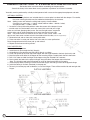
1. Locate the caster pad bracket positions under the corners of the dumper’s frame
-- a swivel caster is to be located at each rear corner (fork truck side) and a rigid
caster at each front (dumping side) corner. Be sure the rigid casters are parallel
to each other and will allow the dumper to roll away from the fork truck side.
Note: Only three casters are used on the 1/4 and 1/2 cubic yard H- series -- two
rigid at each front corner and one swivel in the middle of the rear side (under the hopper base).
2. Remove the bolt and nut from each caster pad bracket.
3. Place one end of a caster pad into the slot at the end of a caster pad bracket.
Raise the opposite end of the caster pad up and reinstall.
4. Repeat for the three remaining corners.
POLY HOPPER LIDS
Refer to the drawings below.
1. Install the main pin through the lid(s) hinge(s).
2. Assemble the hinge brackets onto the ends of the pin, as shown.
3. Place and square up the lid on top of the hopper, with the hinge oriented at the back (fork truck) side.
4. Mark the holes to be drilled in the hopper for the mounting hinges. Double-check the lid’s orientation.
5. Drill 11/32” holes and bolt the hinges to the hopper using the included 5/16” fasteners.
6. Mark and drill the holes for the prop-rod hinges along the side of the hopper, toward the front.
Note: The lid might need to be trimmed with tin snips to allow these hinges to fit properly.
7. Install the prop rod by inserting it into one of the front hinges and sliding it across to the opposite hinge.
8. Install the cotter pin and lock (if desired) in the prop rod.
o The main pin and the prop rod are identical, as are their hinges. There will be two left-side and two right-side
hinges.
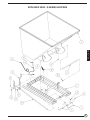
D-STYLE HOPPERS
H-STYLE HOPPERS
2