1
US 20130055055A1
(19) United States
(12) Patent Application Publication (10) Pub. No.: US 2013/0055055 A1
Turcotte et al.
(54)
('75)
(43) Pub. Date:
SYSTEMS AND METHODS FOR LAYOUT OF
GRAPHIC OBJECTS FOR ELECTRONIC
Feb. 28, 2013
Publication Classi?cation
DISPLAY, PRINT OR OTHER OUTPUT
(51)
Int- Cl
G06F 17/00
Inventors; Kenneth A, Turcottea Folsom, CA (Us);
(52)
U.S. Cl. ..................................................... .. 715/201
Daniel A. Kaye, Folsom, CA (US);
Christopher H. Davey, Sacramento, CA
(US); Peter A. Tjeerdsma, Fair Oaks,
CA (US); Michael R. Moore, Folsom,
CA (US)
(73) Assignee: VISAN INDUSTRIES, Folsom, CA
(US)
(2006.01)
(57)
ABSTRACT
Systems and methods for layout of graphic objects such as
photographic images and graphical elements, for electronic
display, print or other output. In accordance With an embodi
ment, a graphic layout logic automatically arranges the
graphic objects Within a target area, including determining a
best combination of roWs and/ or columns of obj ects. Optional
controls can also be provided to alloW manual or user control
(21) App1_ NO; 13/598,424
of, e.g., overlapping, cropping, offsetting, or rotation of the
(22)
graphic objects or images, for aesthetic design or other rea
sons. Examples of the types of graphic objects that can be
arranged or laid out in this manner include digital photo
Filed:
Aug 29, 2012
Related U‘s‘ Application Data
graphs, text, clipart, graphical images, illustrations, software
user rnterfaces, graphrc elements such as icons, buttons,
(60)
Provisional application No. 61/529,798, ?led on Aug.
31, 2011.
menus and Whitespace, user interface Windows, digital Video
or media streams, and other image media.
Gissptay
222
--.. Graphéc Layout
246
“m
Yargei
Area 234
Patent Application Publication
Feb. 28, 2013 Sheet 2 0f 8
US 2013/0055055 A1
25%5Qmng,
av?2%6a
NmKQ Q
5w?23%a@
36%$Q3n2.,
Patent Application Publication
US 2013/0055055 A1
Feb. 28, 2013 Sheet 3 0f 8
fziln3:15.i
MwwMwwMww..-4..ww..u.
i‘*ralystvw§nk
.lits‘
f
ma?Q“0w“uW0EMn3mEQw?;xmihg»QJ vm9m.EE3“$5gm?wxni52?msaxw3og
w“iv1J!lt0qsi!v“ uis
w
M
H
*
m
*
N
*
w
w
N
w
w
*
*
m
w
w
wiiiimi
it”
Ilit“
ti225w
MH
\
w
m
M
*
M
w
*
m
i
»
w
gamma
*
m
N
*H
an
W
H
w
w?
m
1/3m3ma9maw.»
Wm,QN GE
Patent Application Publication
Disgkiay
Feb. 28, 2013 Sheet 4 0f 8
_
18%
.............
.
i,i
m3
1&3
3%
US 2013/0055055 A1
:
E
\
5%
192
194
‘$38
5,,
.
v
Targe‘iv
W
Area 182
FIGURE 4
*i
“Q
3;1
393
Qispiay
we
g
-
1
19?
‘:95
7* 4
;
i
{mama}
W Graméc Layoui
ma
i1;
192
194
m6
I
881 ................................... .,
'8
I
Target
Area 382
FIGURE 5
I’Bispiay
ass
;
$91
§
‘£95
,
:
,“W
{t‘éeviseci}
;
T99
;
192
“34
; 5
:
'
1
a?”
19s
m Target
W
W
W
W
W
W
W
~
W
W
FIGURE 6
W
W
W
W
W
“a
Area
182
Patent Application Publication
Feb. 28, 2013 Sheet 5 0f 8
US 2013/0055055 A1
Receive at Gamguiing Environment, User~speci?ed input Graphic, Objects
andier insimmions to seiem Qtsject‘s fat Dismay andlor Wming
m
?et?mxina {ma 0r mow Tmgai llamas for Arrangement 0?
Seieatad Graphic Ohjmts therein
{3m pmc Laysui magic ?ewnmines Graphia Layout that eptimtzas usaga at space
within ‘me Target; Area far beat fr‘: 0? Saieaied Graphic Qbg‘e sis, inciuding
?xatermining a hast semisinaiion a’? Rows ancélm' Coiumnst and msmbefs
M
205
of Objems m ma Haws andicr Ceéumns, and taismg ims anmum
the) Rumbas‘ sf Qtxiecis and Aspesi {aims sf each Object
Optic-nag‘; {mews i'mm User Manna! ilxmtmis in further meaify Grams Lawn?
if dashed
Prepare Prmwd 1 0131s? Outpué including Graphic Laws: of Seiec’zsti
Gyaphic Obiems, £0? Diapiay within andim Printing on am or mere i-‘roziucis
FIGURE 7
303
M 2m
Patent Application Publication
Feb. 28, 2013 Sheet 6 0f 8
US 2013/0055055 A1
?egm determinatim: o? Gmphix: Layeut' ihai CIQ?E?iHQSS usage at sgsace
wiwén we ‘fame! 3W9 {w i268: ?t of $aiectad Griz {mic Sweats‘ inducing;
dei'ermé?ing a best aomb‘ina?nn of Rows amifar Commas, and numbers, a?"
51391233 in we RQWS arséior Commas: and taking mm sac-aunt the number
sf Obie-ms and Aspect ratios: of each ilibiect
First Pass
Fim maximam mam obiaci in wiumn
Fm a5; abjeu?s in coiumn,
E?aém‘mine acme faster ta make the curwnt object m game width
as me maximum width mm in ma mama‘
$433113 ma sbéevi.
Mimi wsi?omng a? stamina 89 they are samewaé verticaéiiy
am; separated by a Spacing vaiue, and
m 2M
q
Seiarmina Gamma Heig?i # 13mm of actiiusied 0mm h?tigihi? in
003mm + {Nam'bar <2? obiacis ~17} '“ Spacing
Repeat far Bi! Coiumns. keeping; mask of the max Eammn Height {3? aii miumns
?emm: Pass
Far 32; Caiumns an the page,
miarmins scaie fame? is make coiumn 2m same height.
as {he maximum might, GOMTB‘L and
M
2%
gcaie the nbjems in {has wiumn
Rwea’: far alt Peas-ibis Gan?gwations m‘ Rnw$ Oi’ Qeiumnai (chewing the me
that {its mm mm me avaiiabie "marge! Area
Pmvécie f autpm Gmphéa Layoui 1h at aptimizes usage: of agaae wiihin time ‘Page?
Area for mat fit (if Seiemezi Graphi’: Obiesis,
FIGURE 8
M
21%
Patent Application Publication
Feb. 28, 2013 Sheet 7 0f 8
US 2013/0055055 A1
Gi‘aphic Layoui
226
sargeei
Area 224
FIGURE 9
-- Graphic Lay2311i
246
FIGURE 10
Patent Application Publication
Feb. 28, 2013 Sheet 8 0f 8
US 2013/0055055 A1
D‘sgai: y
251?
-~ Gwnhic Lawn?
254;
“W
FlGURE 11
Taigei
Area v252
Feb. 28, 2013
US 2013/0055055 A1
SYSTEMS AND METHODS FOR LAYOUT OF
GRAPHIC OBJECTS FOR ELECTRONIC
DISPLAY, PRINT OR OTHER OUTPUT
COPYRIGHT NOTICE
[0001] A portion of the disclosure of this patent document
contains material Which is subject to copyright protection.
The copyright oWner has no objection to the facsimile repro
duction by anyone of the patent document or the patent dis
closure, as it appears in the Patent and Trademark O?ice
patent ?le or records, but otherWise reserves all copyright
rights Whatsoever.
graphical elements, for electronic display, print or other out
put. In accordance With an embodiment, a graphic layout
logic automatically arranges the graphic objects Within a
target area, including determining a best combination of roWs
and/or columns of objects. Optional controls can also be
provided to alloW manual oruser control of, e. g., overlapping,
cropping, offsetting, or rotation of the graphic objects or
images, for aesthetic design or other reasons. Examples of the
types of graphic objects that can be arranged or laid out in this
manner include digital photographs, text, clipart, graphical
images, illustrations, softWare user interfaces, graphic ele
ments such as icons, buttons, menus and Whitespace, user
interface WindoWs, digital video or media streams, and other
CLAIM OF PRIORITY
[0002] This application claims the bene?t of priority to
United States Provisional Patent Application titled “SYS
TEMS AND METHODS FOR LAYOUT OF IMAGES AND
GRAPHIC ELEMENTS FOR ELECTRONIC DISPLAY OR
PRINT OUTPUT”, Application No. 61/529,798, ?led Aug.
31, 2011, Which application is herein incorporated by refer
ence.
FIELD OF INVENTION
[0003] Embodiments of the present invention are generally
related to computer systems and softWare, and are particu
larly related to systems and methods for enabling layout of
graphic objects, such as photographic images or graphical
elements, for electronic display, print, or other output.
image media.
BRIEF DESCRIPTION OF THE FIGURES
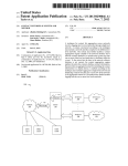
[0008] FIG. 1 illustrates a system for layout of graphic
objects, such as images and graphic elements, for electronic
display or print output, in accordance With an embodiment.
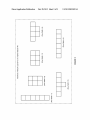
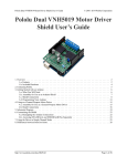
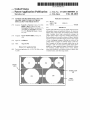
[0009] FIG. 2 illustrates a variety of Ways in Which a plu
rality of graphic objects can be arranged to ?t Within a range
of possible aspect ratios for a target area, in accordance With
an embodiment.
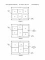
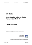
[0010] FIG. 3 illustrates a variety of Ways in Which a plu
rality of graphic objects can be arranged according to roWs or
columns that are balanced for use Within a target area, to
achieve an aesthetically pleasing appearance, in accordance
With an embodiment.
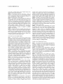
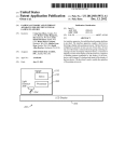
[0011]
FIG. 4 illustrates an example usage of a system for
BACKGROUND
layout of graphic objects, such as images and graphic ele
ments, in Which a plurality of rectangular-aspect objects is
[0004] Layouts of graphical elements, such as digital pho
arranged as a graphic layout, and their siZe and placement
tographs intended for printing on products such as Wall cal
endars, have traditionally been presented using grid or col
subsequently adjusted to cover the target area.
[0012] FIG. 5 further illustrates an example usage of a
lage formats. Both of these formats have their oWn behaviors
and limitations.
system for layout of graphic objects, in Which a plurality of
rectangular-aspect objects is arranged, and their siZe and
[0005] For example, grids are generally rigid, and graphical
placement subsequently adjusted to cover the target area.
elements used thereWith must typically be cropped to ?t
[0013]
Within ?xed-aspect sockets in the grid. This typically requires
user interaction to ensure that the desired parts of the graphi
system for layout of graphic objects, in Which a plurality of
rectangular-aspect objects is arranged, and their siZe and
cal elements are shoWn (e.g., With photographs of people, that
the person’s face is not cut off from the ?nal image). Image
placement subsequently adjusted to cover the target area.
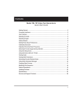
[0014] FIG. 7 illustrates a method for layout of graphic
processing techniques, such as face-recognition, can some
times be used in an attempt to automatically adjust, e.g.,
image crop settings. HoWever, this does not solve the root
With an embodiment.
problem, namely that the graphical elements should not need
to be cropped in the ?rst place.
[0006] Collages are generally more free-form, typically
alloWing the full original area of the graphical elements to be
maintained. HoWever, collages are usually pre-determined to
be aesthetically pleasing, and problems can arise if the
graphic objects do not match the intended aspect of a given
socket (e.g., a landscape vs. portrait orientation), or if they do
not ?t the intended look of the layout. As With grid formats,
the ?xed sockets of a collage are typically laid out in advance,
and graphic elements must be chosen to ?t the aspect ratio of
each socket, or cropped or reduced in siZe. These are the
general areas that embodiments of the invention are intended
FIG. 6 further illustrates an example usage of a
objects for electronic display or print output, in accordance
[0015]
FIG. 8 further illustrates a method for layout of
graphic objects for electronic display or print output, in accor
dance With an embodiment.
[0016]
FIG. 9 illustrates an example usage of a system for
layout of graphic objects, Which includes a “Keep Photos
Original Aspect” or similar option, in accordance With an
embodiment.
[0017] FIG. 10 further illustrates an example usage of a
system for layout of graphic objects, in accordance With an
embodiment.
[0018] FIG. 11 illustrates an example in Which a ?xed-grid
layout is used, illustrating hoW, With such a ?xed-grid the
photographs Would be cropped to a greater degree.
to address.
DETAILED DESCRIPTION
SUMMARY
[0007] Disclosed herein are systems and methods for lay
out of graphic objects such as photographic images and
[0019] As described above, layouts of graphical elements,
such as digital photographs intended for printing on products
such as Wall calendars, have traditionally been presented
Feb. 28, 2013
US 2013/0055055 A1
using grid or collage formats, both of Which formats have
their oWn behaviors and limitations.
[0020]
In accordance With an embodiment, disclosed
herein are systems and methods for layout of graphic objects
such as photographic images and graphical elements, for
electronic display, print or other output.
[0021]
In accordance With an embodiment, the system can
accept graphic objects, including content of any type, in any
quantity, from any source, and automatically arrange those
objects into an aesthetically pleasing layout. A graphic layout
logic can automatically arrange the graphic objects Within a
already stored or otherWise provided at the computing envi
ronment. The graphic layout logic can then determine a
graphic layout that includes an appropriate arrangement of
the selected graphic objects 120, 122, 124. Subsequently, the
graphic layout, together With its graphic objects, can be
printed to a product, or provided as another form of output.
[0029]
In accordance With an embodiment, the graphic lay
out logic is adapted to automatically determine a best ?t of a
selection of graphic objects for use Within a target area, for
example by determining a best combination of roWs and/or
columns, and the number of objects in each roW or column,
target area, including determining a best combination of roWs
and/or columns of objects. Optional controls can also be
provided to alloW manual or user control of, e. g., overlapping,
While taking into account the overall number of objects and
the aspect ratios of each object.
cropping, offsetting, or rotation of images, for aesthetic
design or other reasons.
user interface tools can be provided to enable the optional/
manual control by a user over various algorithmic layout
[0022]
properties, in order to alloW, e.g., intentional overlapping,
Examples of the types of graphic objects that can be
arranged or laid out in this manner include digital photo
graphs, text, clipart, graphical images, illustrations, softWare
user interfaces, graphic elements such as icons, buttons,
menus and Whitespace, user interface WindoWs, digital video
or media streams, and other image media.
System for Layout of Graphic Objects
[0023] As described above, grid formats generally require
that graphic objects used thereWith be cropped to ?t Within
?xed-aspect “sockets” in the grid. Although collage formats
are generally more free-form, collages are usually pre-deter
mined, requiring objects to be cropped or reduced in siZe;
[0030]
In accordance With an embodiment, one or more
offsetting, or rotation of images, for aesthetic design reasons.
Options can also be provided to alloW manual cropping, While
the relative positioning and spacing of the images can be
optimiZed to minimiZe the amount of cropping required to ?t
objects into the layout. The inclusion of such features can
greatly reduce the possibility of important or otherWise
desired image content from being lost (e.g., With photographs
of people, a person’s face), and also minimiZe the amount of
manual or user intervention required, even When using lay
outs With cropped or overlapped images.
Graphic Layout OptimiZation Process
objects may also overlap, in Which case there is danger of one
[0031]
graphic object covering important parts of another object.
out logic is adapted to use a layout optimiZation process to
determine a graphic layout that includes an appropriate
[0024] In accordance With an embodiment, a system and
method is described herein Which can be used to address the
above problems, including enabling layout of graphic
objects, such as photographic images or graphical elements,
for electronic display, print, or other output.
[0025] In accordance With an embodiment, the system
alloWs for automatic and/ or instant application of algorithmi
cally generated grid-like or collage-like layouts, Which can
handle any number of graphic objects, of any combination of
In accordance With an embodiment, the graphic lay
arrangement of graphic objects.
[0032] In accordance With an embodiment, to begin the
process, the selection of graphic objects (Which can be pro
vided by a user as described above, e.g., by uploading digital
image or media ?les) that are to be included in the graphic
layout, are ?rst arranged at a consistent relative siZe, Without
regard to their aspect ratios.
[0033]
To make best use of the available space Within a
aspect ratios, Without requiring the cropping or stretching of
target area, the graphic layout logic can ?rst determine
any object, or manual placement or adjustment.
[0026] FIG. 1 illustrates a system for layout of images and
Whether to use roWs and/or columns, and hoW to arrange the
graphic objects Within those roWs and columns. This can be
graphic elements for electronic display or print output, in
accomplished by examining each of several possible layout
accordance With an embodiment.
con?gurations, including both roW-based and column-based
[0027] As shoWn in FIG. 1, in accordance With an embodi
ment, the system includes a computing environment 102,
that has an overall aspect ratio closest to that of the target area.
con?gurations, and choosing that particular con?guration
such as that provided by a computer, Website, or other com
[0034]
puting environment. The computing environment can include
computer hardWare 104 (e.g., a processor/CPU, memory,
in Which a plurality of graphic objects (in this example, six
storage, or other hardWare). A graphic layout logic 106 is
adapted to automatically arrange a plurality of graphic
objects, prior to printing of the objects on products such as
For example, FIG. 2 illustrates a variety of Ways 140
objects) can be arranged to ?t Within a range of different
possible aspect ratios for a target area, in accordance With an
embodiment. In accordance With an embodiment, the six
objects may be arranged in several possible layout con?gu
softWare applications, printed books, Wall calendars, posters,
rations, With roW Widths from 1 object to 6 objects Wide.
or other products. Optional/manual controls 107 enable a user
Comparing each of these con?gurations against the target
to perform further control of the graphic objects, if desired,
plurality or selection of graphic objects 116, or can provide
area, the system can then select the con?guration that has the
best ?t to the aspect ratio of the target area. The aspect ratio of
each object need not be taken into account at this stage;
instead the objects can be simply placed into roWs or columns
and then siZed the same relative to each other. The objects can
then be shrunk or expanded, so that a largest dimension (e. g.,
the maximum roW Width) ?ts Within the target area, and the
resulting layout analyZed to determine hoW Well it makes use
instructions to utiliZe a selection of graphic objects that are
of the total area available Within the target area.
prior to output. A display 108 enables display of a target area
110, Which contains a graphic layout 112 of the graphic
objects, as determined by the graphic layout logic, and any
optional manual controls.
[0028]
In accordance With an embodiment, a user 114 can
provide (e.g., by uploading digital image or media ?les) a
Feb. 28, 2013
US 2013/0055055 A1
[0035] In accordance With an embodiment, the graphic lay
out optimization process can be duplicated for other possible
layout con?gurations, to determine a best initial layout con
?guration.
gular-aspect graphic objects are arranged as a graphic layout
of tWo roWs, each of three objects, and their size and place
ment subsequently adjusted to cover a target area.
[0043] As shoWn in FIG. 4, in accordance With an embodi
ment, a display 180 and target area 182 layout, initially of tWo
[0036] As shoWn in FIG. 2, in accordance With an embodi
ment, a rectangular target area is shoWn, and a plurality of
square or rectangular objects are arranged geometrically to
best ?t the aspect ratio of that rectangular target area. A
typical application of such environment can be a rectangular
target area. As shoWn in FIG. 4, a ?rst step includes laying out
screen area representing a photo book page. In accordance
the objects according to a layout optimization algorithm, With
With other embodiments, the target area can alternatively be
all objects at the same relative size, regardless of their aspect
ratio.
circular, irregular, or otherWise-shaped, as may the graphic
objects to be arranged therein.
Uneven Numbers of RoWs and/or Columns
[0037] In accordance With an embodiment, When the num
ber of graphic objects is not evenly divisible into roWs or
columns that optimally ?t a target area, the roWs or columns
can be automatically balanced to achieve an aesthetically
pleasing appearance using appropriate horizontal or vertical
centering. These possible arrangements can then be evaluated
tWice for optimal ?t4one pass using columns, and another
roWs, each of three objects, are determined as a best initial ?t
of six objects 191, 192, 193, 194, 195, 196 into a rectangular
[0044]
Again, in the example illustrated, a rectangular tar
get area is shoWn, and a plurality of square or rectangular
objects are arranged geometrically to best ?t the aspect ratio
of that target area. In accordance With other embodiments, the
target area can be circular, irregular, or otherWise-shaped, as
may the graphic objects to be arranged therein.
[0045]
As shoWn in FIG. 5, in a second step, an initial
graphic layout 198 is determined in Which all of the graphic
objects Within a particular column are made the same Width
pass using roWs.
For example, FIG. 3 illustrates a variety of Ways in
(or all of the objects Within a particular roW the same height).
Which a plurality of graphic objects (in these examples, seven
[0038]
or eight objects) can be arranged according to an uneven
This can be accomplished by scaling the sizes of the objects
Without cropping. As shoWn in FIG. 5, portrait objects may be
number of roWs or columns that are balanced for use Within a
noW larger in order to match the Width of the landscape
target area, to achieve an aesthetically pleasing appearance, in
objects, and the overall height of the layout has increased, but
accordance With an embodiment.
is still Within the layout area.
[0039] As shoWn in FIG. 3, in accordance With an embodi
ment, in a ?rst example, seven graphic objects 150 are
arranged on a display 152, Within a target area 153, and are
either sorted by roWs ?rst 154, or by columns ?rst 156, so as
to determine a layout con?guration that achieves an aestheti
[0046] As shoWn in FIG. 6, in a third step, an adjusted or
revised graphic layout 199 is determined in Which all of the
cally pleasing appearance using appropriate horizontal or
vertical centering. As further shoWn in FIG. 3, in accordance
With an embodiment, in a second example, eight graphic
columns are made the same height (or all of the roWs the same
Width). This is accomplished by scaling all of the columns
(and the graphic objects Within them).As shoWn in FIG. 6, the
tWo right columns are narroWer, and the left column is Wider,
but they are all the same height.
objects 160 are arranged on a display 162, Within a target area
[0047]
163, and are again either sorted by roWs ?rst 164, or by
shoWn in FIG. 6 has the appearance of a grid, none of the
columns ?rst 166, so as to similarly achieve an aesthetically
graphic objects Were cropped in the process of adjusting the
pleasing appearance using appropriate horizontal or vertical
layout. Instead, their relative sizes are effectively varied so
that they e?iciently ?t Within the target area. A characteristic
centering.
Graphic Layout Adjustment
[0040]
In accordance With an embodiment, in order to auto
matically arrange graphic objects into a pseudo-grid graphic
layout, that looks aesthetically much like a grid, but Without
those compromises necessary to ?t Within a ?xed-grid, the
arrangement of the objects can be adjusted or revised by a
series of adjustments to their relative sizes, rather than just
?tting those objects into a pre-determined grid.
[0041] In accordance With an embodiment, automatic
adjustments can also be made to accommodate ?xed inputs
It Will be noted that, although the overall result
of this approach is that the resulting graphic pseudo-grid
graphic layout may not alWays completely ?ll the target area;
hoWever, the graphic layout is alWays optimized to ?ll the
largest possible area Without cropping the graphic objects. In
accordance With an embodiment, described in further detail
beloW With respect to photographic images, an option can be
provided to alloW cropping of the graphic objects if the desire
is to completely ?ll the target area.
[0048] In accordance With an embodiment, an example
pseudo code is provided beloW Which can be used for per
forming the layout steps described above. The example
for a particular target area or object, such as a ?xed aspect
pseudo code is provided for the purposes of illustration and
ratio of the desired target area containing the layout, or the
description. It is not intended to be exhaustive or to limit the
aspect ratios of each object Within the layout.
invention to the precise forms disclosed, and many modi?ca
tions and variations Will be apparent to the practitioner skilled
[0042]
FIGS. 4-6 illustrate an example usage of a system
for layout of graphic objects, in Which a plurality of rectan
in the art.
// Graphic objects are already laid out as determined by an initial graphic layout optimization
process //
First Pass:
// to build uniform Width columns ofobjects //
Size = 1.0
// initial size of objects in a grid arrangement //
Feb. 28, 2013
US 2013/0055055 A1
-continued
Spacing = 0.1 // inter-object spacing as a % ofinitial grid spacing (arbitrary value) //
Find maximum Width object in column
For all objects in column {
Determine scale factor to make the current object the same Width as the maximum Width
object in the column
Scale the object
Adjust positioning of objects so they are centered vertically, and separated by the
Spacing value
Column Height = sum of adjusted object heights in column + (Number ofobjects —1) *
Spacing }
Repeat for all Columns, keeping track ofthe max Column Height ofall columns
Second Pass:
For all Columns on the page {
Determine scale factor to make column the same height as the maximum height column
Scale the objects in the column }
Adjust column positioning so they are centered horizontally, and separated by the Spacing
value
// The above provides a layout of obj ects of arbitrary size; a normalization scale factor can be
calculated to make the layout ?t into the target area //
Repeat for all possible con?gurations ofroWs or columns, choosing the one that ?ts best into the
available target area.
[0049] FIG. 7 illustrates a method for layout of graphic
objects for electronic display or print output, in accordance
With an embodiment. As shoWn in FIG. 7, in accordance With
an embodiment, at step 202, the system receives a plurality of
user-speci?ed input graphic objects and/or instructions to
select graphic objects for display and/or printing. As
described previously, a user can provide the graphic objects,
e.g., by uploading digital image or media ?les.
[0050]
At step 204, the system determines one or more
target areas for arrangement of the selected graphic objects
therein.
[0051] At step 206, a graphic layout logic determines a
graphic layout that optimizes usage of space Within the target
area for a best ?t of selected graphic objects, including deter
mining a best combination of roWs and/ or columns, and num
bers of objects in the roWs and/or columns, and taking into
account the number of objects and aspect ratios of each
object.
[0052]
At step 208, the system optionally receives from the
user manual controls to further modify graphic layout if
desired.
[0053] At step 210, the system prepares printed/other out
put including a graphic layout of the selected graphic objects,
for display Within and/or printing on one or more products.
[0054]
FIG. 8 further illustrates a method for layout of
images and graphic elements for electronic display or print
output, in accordance With an embodiment. As shoWn in FIG.
8, at step 212, the graphic layout logic determines a graphic
layout that optimizes usage of space Within the target area for
a best ?t of selected graphic objects.
[0055] At step 214, during a ?rst pass, the graphic layout
logic builds uniform height roWs of objects, including, in an
embodiment, ?nding a maximum Width graphic object in a
column, and, for all objects in a column, determining a scale
factor to make the current object the same Width as the maxi
mum Width object in the column, scaling the object, adjusting
the positioning of objects so they are centered vertically, and
separated by a spacing value, and determining a column
height based on the sum of adjusted object heights in the
make the columns the same height as the maximum height
column, and scaling the objects in the column.
[0057] At step 216, the above steps are repeated for several
(in some instances, all) possible con?gurations of roWs or
columns, ultimately selecting the con?guration or layout of
graphic objects that that ?ts best into the target area.
[0058] At step 218, the system provides/outputs the graphic
layout.
[0059]
The above examples generally describe roW-?rst
optimization. In accordance With an embodiment, the optimi
zation can also be column-?rst, in Which case during a ?rst
pass, the graphic layout logic can build uniform Width col
umns of objects, including, for all objects in a column deter
mining an objects height, Width, and positioning; determine a
maximum column height, Which is repeated for all roWs,
keeping track of the maximum column height; and, during a
second pass, for all roWs on the page, determine a scale factor
to make the columns the same height as the maximum height
column and to scale the objects in the column.
Optional Features for Use With Photograph Layouts
[0060] In accordance With an embodiment, When the sys
tem is used to generate a layout containing ?xed-aspect
objects, such as digital photographs, an option can be pro
vided to alloW cropping of the photographs, if the user’s
desire is that the graphic objects (photographs) completely ?ll
the target area. In this case, the layout optimization process is
?rst applied, as described above, in order to make the best use
of space Within the target area Without cropping. Then, an
initial graphic layout in the form of a pseudo-grid is stretched
to completely ?ll the target area, providing the ?nal, adjusted
or revised graphic layout. The aspect ratios of the photo
graphs must of course be modi?ed to achieve this stretching,
Which results in some cropping of the photographs. However,
because the layout optimization has ?rst been applied, the
amount of cropping required is greatly minimized compared
With approaches that arbitrarily ?t photographs into a ?xed
grid pattern.
Optimized Layout With/Without Cropping Feature
column, and repeating for all columns, keeping track of the
[0061]
maximum column height of all columns.
[0056] At step 215, during a second pass, the graphic lay
for layout of graphic objects, such as digital photographs,
out, for all columns on the page, determines a scale factor to
FIGS. 9-10 illustrate an example usage of a system
Which includes a “Keep Photos Original Aspect” or similar
option, in accordance With an embodiment.
Feb. 28, 2013
US 2013/0055055 A1
As shown in FIG. 9, a display 222 can include a
[0070] Keep Objects Original Aspect (toggle)iallows
target area 224, for which a “Keep Photos Original Aspect”
disabling of the aspect-ratio constraint on objects, allow
ing the layout to ?ll the user’s de?ned layout area. The
[0062]
option has been enabled. Because the photographs 231, 232,
233, 234, 235 are fully intact, the initial graphic layout in the
form of a pseudo-grid 226 may not ?ll the entire target area
layout optimiZation is still performed however, which
minimiZes the amount of object cropping required.
indicated by the dotted line with square handles.
[0063] As shown in FIG. 10, in which the “Keep Photos
[0071] Flip Layout Horizontally (toggle)ireverses the
Original Aspect” option has been disabled, by allowing the
[0072] Flip Layout Vertically (toggle)ireverses the
photographs to be cropped slightly, the adjusted or revised
graphic layout 240 may be stretched to ?ll the entire layout
area. Note that in this example, the top and bottom of all of the
photographs are slightly cropped to better ?t the target area. If
the layout optimiZation had chosen a different aspect for the
optimiZed layout, the left and right edges might have been
cropped. In accordance with an embodiment, a device such as
a graphical user interface “hand” can be provided, so that the
user can manually shift a photograph to change the area that
is being cropped.
Comparison with Non-Optimized (Cropped) Layout
[0064]
FIG. 11 illustrates an example in which a ?xed-grid
layout is used, illustrating how, with such a ?xed-grid the
graphic objects, such as digital photographs, would be
cropped to a greater degree. As shown in FIG. 11, which
illustrates a display 250 that includes a target area 252,
because the layout 254 has not been optimiZed, and the sock
ets for each photo are ?xed dimensions, the photographs must
be cropped to a much more signi?cant degree. The above
techniques can be used to reduce this shortcoming.
Additional Aesthetic Design Properties
order of columns, or the objects within rows.
order of rows, or the objects within columns.
[0073] Spacing (value in percentage, for example, rela
tive to the siZe of a photo)iincreases or decreases the
spacing between objects in the layout. If a “both uni
form” setting is enabled, spacing between all objects
will be uniform. Negative values allow overlapping of
objects.
[0074]
Rotation (set of preset or adjustable values)i
provides a variety of rotation settings using a focus
point.
[0075]
Rotation Randomness (value +—)iapplies ran
dom values to increase or decrease the amount of rota
tion determined above, providing a more hand placed
feel
[0076]
Offset rows/columns (value in percentage, for
example)iskews the rows or columns in opposite
directions relative to each other, breaking up the unifor
mity of the graphic layout.
[0077] Offset objects (value in percentage, for
example)iskews objects at a right angle to their row or
column, breaking up the uniformity of each row or col
umn
[0065] In accordance with an embodiment, a range of prop
erties or controls can optionally be provided, to allow for
[0078]
In varying combinations, the above parameters per
below, although the examples provided are not intended to be
mit the creation of a wide variety of designs. They can also be
used to create graphic layouts that aesthetically look much
like collages, but are better optimiZed than any ?xed approach
to ?ll the area with the particular objects at hand.
exhaustive or to limit the invention to the precise forms dis
closed.
Layout Presets
[0066] The ?rst two properties described below (uniform
spacing, and uniform rows/columns toggle controls) can be
used to provide control over the “Graphic Layout Adjust
ment” steps leading up to the creation of a graphic layout, i.e.,
while many of the foregoing examples have described cre
ation of a uniform pseudo-grid graphic layout, the uniform
the above properties can be saved in a “layout preset”, allow
ing a designer or end-user to create a re-usable layout “style”.
This preset can then be applied to any number of objects of
any aspect ratio while maintaining a consistent “look” to the
spacing and uniform rows/ columns properties can be used to
create layouts that may be somewhat non-uniform, but are
tions within a given context, such as different pages within a
book, a set of posters, a set of commemorative plates or mugs,
further aesthetic design or control over the graphic layout
choices, and to further demonstrate advantages over rigidly
aligned grids. Examples of such properties are provided
nonetheless aesthetically pleasing.
[0067] Uniform spacing (toggle)iallows disabling of
the adjustment in the second step of the graphic layout
adjustment described above (i.e., determining an initial
graphic layout in which all of the graphic objects within
[0079]
In accordance with an embodiment, some or all of
layout. This may be especially useful for multiple applica
etc. each with different speci?c objects placed on each mem
ber of a set.
Software User Interface Layouts
a particular column are made the same width, or all of the
[0080]
objects within a particular row the same height).
treated as a set of screens with buttons or menus to permit
[0068] Uniform rows/columns (toggle)iallows dis
abling of the adjustment in the third step of the graphic
layout adjustment described above (i.e., determining an
adjusted or revised graphic layout in which all of the
Software user interfaces have traditionally been
navigation between the screens. Each software application
thus has its own internal use-?ow, and switching between
applications typically involved an abrupt change in the user
experience.
columns are made the same height, or all of the rows the
[0081]
same width).
and methods can be provided to accept as graphic objects a
combination of user interfaces of any arbitrary dimensions
[0069] Additional examples of such graphic layout proper
In accordance with various embodiments, systems
ties are described below, again the examples provided are not
from any number of applications, and automatically arrange
intended to be exhaustive or to limit the invention to the
them into a consistent layout on the screen, permitting easier
navigation between screens within an application, or between
precise forms disclosed.
Feb. 28, 2013
US 2013/0055055 A1
multiple separate applications, While also optimizing the use
of available space on the screen for each and all user inter
faces.
[0082]
to the precise forms disclosed. Many modi?cations and varia
tions Will be apparent to the practitioner skilled in the art. The
embodiments Were chosen and described in order to best
For example, in accordance With an embodiment,
the system or method can be used to lay out user interfaces for
explain the principles of the invention and its practical appli
cation, thereby enabling others skilled in the art to understand
a software application, Wherein the graphic objects are but
the invention for various embodiments and With various
tons on a user interface; or a collection of different user
modi?cations that are suited to the particular use contem
interface WindoWs intended to be shoWn on a single screen.
plated. It is intended that the scope of the invention be de?ned
Additional examples include using the system or method to
arrange different applications on the display of a smart phone,
or different programs running on a personal computing
device (e.g., an alternative Way of displaying running Win
doWs similar in function to hitting the “WindoW-key+ta ” in
by the folloWing claims and their equivalence.
What is claimed is:
1. A system for enabling layout of graphic objects, such as
photographic images or graphical elements, for electronic
display, print, or other output, comprising:
Windows).
a computing environment Which includes a computer hard
[0083] In accordance With an embodiment, animation tech
niques may also be used to maintain visual context When
changing focus betWeen user interfaces in the layout, or the
addition or removal of interfaces from the layout.
a graphic layout logic Which is adapted to automatically
arrange a plurality of graphic objects;
a display Which includes a target area for use With the
Additional Applications and Use Cases
Wherein the system can receive a selection of the graphic
Ware;
graphic objects; and
[0084] Although many of the embodiments described
herein illustrate layout of graphic objects such as softWare
images, or digital photographs, the systems, methods and
techniques described herein can be similarly applied to other
types of page layout, softWare interface, or general layout of
objects. As another example, the system or method can be
provided as part of a computer-based, online or other system
or softWare application, such as a photo-sharing application
Which provides a user interface and alloWs a user to upload
objects, and Wherein the graphic layout logic automati
cally scales and arranges the selection of the graphic
objects as a graphic layout Within the target area, to make
use of available space Within the target area, or to meet
one or more speci?ed design criteria.
2. The system of claim 1, Wherein the graphic layout logic
is adapted to
examine several possible layout con?gurations for the
graphic objects Within the target area, including both
roW-based and column-based con?gurations, and
and display an arrangement of photographs and other graphic
objects Within that user interface, prior to printing or other
usage. The techniques described herein can also be applied by
determine a con?guration that has an overall aspect ratio
closest to the available target area.
a person skilled in the arts to other similar applications, such
as arranging multiple video or media streams into a combined
3. The system of claim 2, Wherein the graphic layout logic
automatically scales and arranges the selection of the graphic
objects as a graphic layout, according to a layout optimization
image, laying out multiple images onto a T-shirt, plate, or
coffee mug, or a Wide variety of other products and applica
tions related to both the production of tangible ?nal output
process, to optimally ?ll the target area, and With or Without
products or arranging objects on a user interface or display
screen for various softWare or hardWare applications.
4. The system of claim 1, Wherein the system is provided as
part of a computer-based, online, or other application, Which
[0085]
provides a user interface and Which alloWs a user to select and
The present invention may be conveniently imple
cropping or distorting the graphic objects.
mented using one or more conventional general purpose or
display an arrangement of graphic objects as a graphic layout
specialiZed digital computer, computing device, machine, or
Within the user interface, prior to printing or other usage.
microprocessor, including one or more processors, memory
and/or computer readable storage media programmed
according to the teachings of the present disclosure. Appro
priate softWare coding can readily be prepared by skilled
5. The system of claim 1, Wherein one or more of the
graphic objects are softWare images such as digital photo
graphs, text, clipart, graphical elements, or illustrations.
programmers based on the teachings of the present disclo
6. The system of claim 1, Wherein one or more of the
graphic objects are softWare user interfaces, elements such as
sure, as Will be apparent to those skilled in the softWare art.
buttons, menus and Whitespace, and other image media.
[0086]
7. The system of claim 1, Wherein one or more of the
graphic objects are different user interface WindoWs that are
to be shoWn on a single interface screen With multiple Win
doWs.
8. The system of claim 1, Wherein one or more of the
graphic objects are a video or media stream to be arranged
In some embodiments, the present invention
includes a computer program product Which is a non-transi
tory storage medium or computer readable medium (media)
having instructions stored thereon/in Which can be used to
program a computer to perform any of the processes of the
present invention. The storage medium can include, but is not
limited to, any type of disk including ?oppy disks, optical
discs, DVD, CD-ROMs, microdrive, and magneto-optical
disks, ROMs, RAMs, EPROMs, EEPROMs, DRAMs,
VRAMs, ?ash memory devices, magnetic or optical cards,
nanosystems (including molecular memory lCs), or any type
into a combined image, and to be displayed Within a single
display area.
9. The system of claim 1, Wherein the system enables a user
to associate properties With a graphic layout to alloW for
aesthetic layout design or control choices other than a uni
of media or device suitable for storing instructions and/or
data.
form pseudo-grid layout.
[0087]
one or more uniform spacing and uniform roWs/columns
The foregoing description of the present invention
10. The system of claim 9, Wherein the properties include
has been provided for the purposes of illustration and descrip
toggle controls, Which can be used to create layouts that are
tion. It is not intended to be exhaustive or to limit the invention
non-uniform, but are aesthetically pleasing.
Feb. 28, 2013
US 2013/0055055 A1
11. The system of claim 9, wherein the properties include
one or more options to keep an objects original aspect, ?ip a
layout horizontally, ?ip a layout vertically, adjust spacing,
adjust rotation, adjust rotation randomness, adjust offset
roWs/columns, and offset objects.
12.A method for layout of images and graphic elements for
electronic display or print output, comprising the steps of:
providing, at a computing environment Which includes a
computer hardWare, a graphic layout logic Which is
adapted to automatically arrange a plurality of graphic
objects;
displaying a target area for use With the graphic objects;
and
receiving a selection of the graphic objects, and automati
cally scaling and arranging the selection of the graphic
19. The method of claim 12, Wherein one or more of the
graphic objects are a video or media stream to be arranged
into a combined image, and to be displayed Within a single
display area.
20. A non-transitory computer readable storage medium,
including instructions stored thereon, Which When read and
executed by a computer, cause the computer to perform the
steps comprising:
providing, at a computing environment Which includes a
computer hardWare, a graphic layout logic Which is
adapted to automatically arrange a plurality of graphic
objects;
displaying a target area for use With the graphic objects;
and
receiving a selection of the graphic objects, and automati
cally scaling and arranging the selection of the graphic
objects as a graphic layout Within the target area, to make
objects as a graphic layout Within the target area, to make
use of available space Within the target area, or to meet
one or more speci?ed design criteria.
best use of available space Within the target area, or to
meet one or more speci?ed design criteria.
13. The method of claim 12, Wherein the graphic layout
logic is adapted to
examine several possible layout con?gurations for the
graphic objects Within the target area, including both
roW-based and column-based con?gurations, and
photographic images or graphical elements, for electronic
display, print, or other output, comprising:
determine a con?guration that has an overall aspect ratio
closest to the available target area.
a graphic layout logic Which is adapted to automatically
arrange a plurality of graphic objects;
14. The method of claim 13, Wherein the graphic layout
logic automatically scales and arranges the selection of the
graphic objects as a graphic layout, according to a layout
optimization process, to optimally ?ll the target area, and With
or Without cropping or distorting the graphic objects.
15. The method of claim 12, Wherein the system is pro
a display Which includes a target area for use With the
vided as part of a computer-based, online, or other applica
tion, Which provides a user interface and Which alloWs a user
21 . A system for enabling layout of graphic objects, such as
a computing environment Which includes a computer hard
Ware;
graphic objects;
Wherein the system can receive a selection of the graphic
objects, and Wherein the graphic layout logic automati
cally scales and arranges the selection of the graphic
objects as a graphic layout Within the target area, to make
use of available space Within the target area, or to meet
one or more speci?ed design criteria; and
to select and display an arrangement of graphic objects as a
Wherein the graphic layout logic automatically scales and
graphic layout Within the user interface, prior to printing or
arranges the selection of the graphic objects as a graphic
layout, according to a layout optimiZation process, to
other usage.
16. The method of claim 12, Wherein one or more of the
graphic objects are softWare images such as digital photo
graphs, text, clipar‘t, graphical elements, or illustrations.
17. The method of claim 12, Wherein one or more of the
graphic objects are softWare user interfaces, elements such as
buttons, menus and Whitespace, and other image media.
18. The method of claim 12, Wherein one or more of the
graphic objects are different user interface WindoWs that are
to be shoWn on a single interface screen With multiple Win
doWs.
optimally ?ll the target area, and With or Without crop
ping or distorting the graphic objects.
22. The system of claim 21, Wherein the graphic layout
logic is adapted to
examine several possible layout con?gurations for the
graphic objects Within the target area, including both
roW-based and column-based con?gurations, and
determine a con?guration that has an overall aspect ratio
closest to the available target area.
*
*
*
*
*