1
Oki Data CONFIDENTIAL
PRINTING SOLUTIONS
C3400n
MAINTENANCE MANUAL
Oki Data CONFIDENTIAL
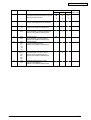
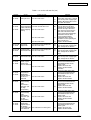
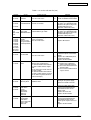
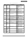
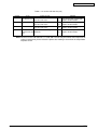
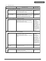
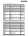
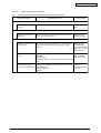
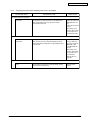
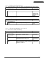
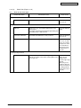
History of Revision
Corrected items
Rev.No.
Date
No.
1
2006-04-27
43163501TH Rev. 1
Page
Description of change
ISSUE
Person in
charge
MD11 Sunaga
2/
Oki Data CONFIDENTIAL
Preface
This manual explains the maintenance methods of C3400n.
This manual is prepared for the maintenance person. In regard to the handling methods of C3400n
please refer to the User’s Manual.
Note! • Contents of this manual is subject to change without notice.
• While all reasonable efforts have been made to make this document as accurate
and helpful as possible, we make no warranty of any kind, expressed or implied,
as to the accuracy of the information contained herein. Oki Data assumes no
responsibility to the damages caused or claimed to have been caused by the user
as a result of repair, adjustment and/or change using this manual.
• Parts of this product are delicate and can be damaged unless properly handled. We
strongly recommend the user to maintain the product at the hand of the registered
maintenance person of our company
• Before starting the maintenance work, please neutralize the static electricity.
43163501TH Rev. 1
3/
Oki Data CONFIDENTIAL
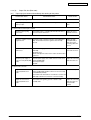
Table of contents
1
CONFIGURATION ............................................................................................7
1.1
1.2
1.3
1.4
1.5
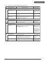
2.
OPERATION DESCRIPTION .........................................................................16
2.1
2.2
3.
Electrophotographic Process Mechanism ................................................................... 16
Printing Process ........................................................................................................... 21
PRINTER INSTALLATION .............................................................................31
3.2
3.3
3.4
3.5
3.6
3.7
3.8
3.9
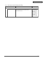
4.
System Configuration ..................................................................................................... 7
Structure of Printer ......................................................................................................... 9
Offer of Options ........................................................................................................... 10
Specifications ............................................................................................................... 11
Interface Specification .................................................................................................. 14
1.5.1 USB Interface Specification ............................................................................ 14
1.5.1.1 Outline of USB Interface ..................................................................... 14
1.5.1.2 USB Interface Connector and Cable .................................................. 14
1.5.1.3 UBS Interface Signal .......................................................................... 14
1.5.2 Network Interface Specification ...................................................................... 15
1.5.2.1 Outline of Network Interface ............................................................... 15
1.5.2.2 Network Interface Connector and Cable ............................................ 15
1.5.2.3 Network Interface Signal .................................................................... 15
Printer Unpacking Procedure ......................................................................................
Printer Installation Instructions ....................................................................................
Packed Units and Attachments ...................................................................................
Assembly Procedure ....................................................................................................
3.5.1 Printer Main Body ............................................................................................
3.5.2 Power Cable Connection .................................................................................
3.5.3 Installation of Optional Components ...............................................................
3.5.4 Confirm the Recognition of Option ..................................................................
Status Page Print .........................................................................................................
Network Information Print ............................................................................................
Connection Procedures ................................................................................................
Checking of User Paper ..............................................................................................
33
34
35
36
36
42
44
48
49
50
51
53
REPLACEMENT OF PARTS .........................................................................54
4.1
4.2
Precautions on the replacement of parts ...................................................................
Part replacement methods ..........................................................................................
4.2.1 Left side cover .................................................................................................
4.2.2 Right side cover ...............................................................................................
4.2.3 Rear cover (Top/Bottom) .................................................................................
4.2.4 Front cover ......................................................................................................
4.2.5 Top cover assembly .........................................................................................
4.2.6 Top cover .........................................................................................................
4.2.7 LED assembly/ LED assembly spring .............................................................
4.2.8 RFID assembly ................................................................................................
4.2.9 Control pane assembly ....................................................................................
4.2.10 WHI board .......................................................................................................
4.2.11 Feeder unit ......................................................................................................
43163501TH Rev. 1
54
56
56
57
58
59
60
61
62
63
64
65
66
4/
Oki Data CONFIDENTIAL
4.3
5.
5.5
Maintenance Utility (Not Available) ............................................................................. 93
Various printing of the printer unit with controller ...................................................... 96
Switch pressing function when power supply is turned on ....................................... 96
Settings after Parts Replacement ............................................................................... 97
5.4.1 Notes when exchanging the main circuit board and
EEPROM setting after the exchange of BLA circuit board .............................. 97
About the manual setting of density correction ........................................................ 101
REGULAR MAINTENANCE .........................................................................102
6.1
6.2
6.3
6.4
6.5
7.
67
68
69
70
71
72
73
74
75
77
78
79
80
MAINTENANCE MENU ..................................................................................93
5.1
5.2
5.3
5.4
6.
4.2.12 Manual feeder unit ...........................................................................................
4.2.13 Face up tray ....................................................................................................
4.2.14 Guide eject assembly ......................................................................................
4.2.15 Eject roller .......................................................................................................
4.2.16 Plate shield front ..............................................................................................
4.2.17 Color registration assembly .............................................................................
4.2.18 Plate shield rear ..............................................................................................
4.2.19 PRE board (toner sensor board)/ Gear idle dram ...........................................
4.2.20 Main motor/ Solenoid ......................................................................................
4.2.21 Belt motor/ High voltage board/ Cover open switch ........................................
4.2.22 Low voltage power supply/ Low voltage fan ....................................................
4.2.23 BLA Board (Main Board) .................................................................................
Lubricating points .........................................................................................................
Recommended substitutes .........................................................................................
Cleaning......................................................................................................................
Cleaning LED lens array ...........................................................................................
Cleaning the pick-up roller ........................................................................................
Cleaning the inside of the printer .............................................................................
102
102
102
104
105
TROUBLESHOOTING PROCEDURES .......................................................107
7.1
7.2
7.3
7.4
7.5
Precautions prior to repair .........................................................................................
Items to be checked prior to taking action on abnormal images ...........................
Precautions when taking action on abnormal images .............................................
Preparations for troubleshooting ...............................................................................
Troubleshooting method ............................................................................................
7.5.1 LED Message List ............................................................................................
7.5.2 Preparing for troubleshooting ........................................................................
7.5.2.(1) LCD Display Malfunction ..............................................................
7.5.2.(2) Irregular Operation of the device after turning on the power .......
7.5.2.(3) Paper Feed Jam (Error 391:1st tray) ...........................................
7.5.2.(4) Paper Feed Jam (Error 390: Multipurpose tray) ..........................
7.5.2.(5) Paper transport jam (Error 381) ...................................................
7.5.2.(6) Paper Exit Jam (Error 382) ..........................................................
7.5.2.(7) Paper Size Error (Error 400) ........................................................
7.5.2.(8) ID Unit Up-Down Error (Service Call 140-143) ............................
7.5.2.(9) Fuser Error (Error 170-177) .........................................................
7.5.2.(10) Motor Fan Error(Error 127) ..........................................................
7.5.2.(11) Print Speed is Slow (Low Performance) ......................................
43163501TH Rev. 1
107
107
107
107
107
108
127
129
130
139
141
143
148
151
152
153
154
155
5/
Oki Data CONFIDENTIAL
7.5.3
7.6
8.
7.5.4
7.5.5
Fuse
7.5.2.(12) LED head is not recognized(Error 131,132,133,134) ..................
7.5.2.(13) Toner cartridge is not recognized (Error 540, 541, 542, 543) ......
7.5.2.(14) Fuse Cut Error (Error 150-155) ....................................................
7.5.2.(15) Dew Condensation Errors (Error 123)..........................................
7.5.2.(16) RFID Related Error (Error 610-613) ..............................................
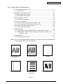
Image Problem Troubleshooting ...................................................................
7.5.3.(1) Color is totally pale (Figure 7.2 A ) ...............................................
7.5.3.(2) Background is dirty (Figure 7.2 B )...............................................
7.5.3.(3) Blank Print (Figure 7.2 C )............................................................
7.5.3.(4) Vertical lines are printed ...............................................................
7.5.3.(5) Cyclic Print Trouble (Refer to Figure 7.2 E ) ................................
7.5.3.(6) Color drift is wide..........................................................................
7.5.3.(7) Solid Black Print ...........................................................................
Response after Flash compulsive initialization ..............................................
Network Troubleshooting ...............................................................................
Checking ...........................................................................................................
155
156
157
158
159
160
161
162
163
164
165
166
167
168
169
170
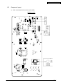
CONNECTION DIAGRAMS .........................................................................171
8.1
8.2
Check of resistance values ....................................................................................... 171
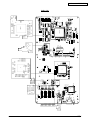
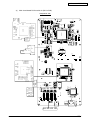
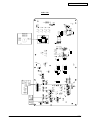
Component layout ...................................................................................................... 174
43163501TH Rev. 1
6/
43163501TH Rev. 1
LED3
Y Toner
Sensor
M Toner
Sensor
C Toner
Sensor
LED
FUSE
Y-ID
3
LED
FUSE
K-ID
3
UP/DOWN
Sensor
2
2
3
M-ID
LED
FUSE
2
RFID
PCB
SW2
AMP2
ELC5
ELC10
10
5
Cover
Open Sw
ELC10
JST5
ELC7
ELC24
High Voltage Power Unit
3
C-ID
LED
FUSE
2
ID Fuse-Cut terminal
K Toner
Sensor
C-ANT
C-Tag
2
2
2
2
SW1
Toner Sensor PCB
Y-ANT
M-ANT
Y-Tag
K-ANT
LED2
M-Tag
K-Tag
LED1
24
ELC24
ELC24
ENV Sensor
4
Belt Unit
BELT
FUSE
12
3
DCON I/F
LSYNC
DCON
4
PU
JST12
Environment Temoerature/
Humidity Signal,
High Pressure I/F, Cover Open
ELC12
EEPROM
FAN
3
JST3
14
1st
P.E
JST14
5V, 24V
0VL,0VP
20MHz
JST3
Color Blur,
Density,
Thermistor signal
FLASH
8M
50MHz
Stand-by
FAN
AC-SW
2
JST3
2
Low Voltage Power Unit
5V→3.3V
5V→1.5V
Regulator
LEISUS
Command I/F
ASIC
(Spilytas)
ASIC(ARMORED)
HEADSEL
Belt Consumable Fuse
75Ω
RFID
Operator
Panel
1
BOURBON
2
JST17
AC
HRS2-10
ID
M
HEAT
M
BELT
M
IDUP
M
HOP
Solenoid
Reg-R
Sensor
HRS2-10
FUSE
LOW-TH
FRM-TH
UP-TH
SIDE-TH
Temperature
Sensor
Fuser Unit
10
MOLEX10
MOLEX5
MOLEX5
Density
Sensor
5
AMP3
AMP3
EXIT
Sensor
3
Rear Sensor Relay PCB
Reg-L
Sensor
MOLEX6
AMP4
AMP4
AMP10
HOP
M
WR
IN1
IN2
Sensor Sensor Sensor
Front Sensor PCB
AMP4
AMP5
Heater Thermistor x 4
Consumable Fuse
17
4
4
4
2
10
4
5
AC Inlet
JST3
EL
JST4
AMP4
AMP5
JST2
AMP10
AMP4
AMP5
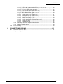
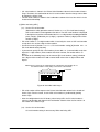
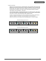
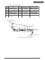
System Configuration
7
24
ELC24
ELC24
OPTION
RAM
1.1
JST7
24
ELC24
ELC24
CU
CONFIGURATION
Operation Panel PCB
24
ELC24
Network I/F
1
C LED HEAD
M LED HEAD
Y LED HEAD
K LED HEAD
USB 2.0
Oki Data CONFIDENTIAL
C3400n
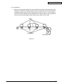
The system configuration of this product is shown in Figure 1-1-1.
Figure 1-1-1
7/
Oki Data CONFIDENTIAL
43163501TH Rev. 1
8/
Oki Data CONFIDENTIAL
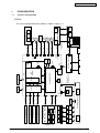
1.2
Structure of Printer
The insides of C3400n printers are composed of the following parts.
•
•
•
•
•
Electronic photography process part
Paper path
Control part (CU part/PU part)
Operation panel
Power supply parts (high voltage part/low voltage part)
Figure 1-2 shows the composition of the printer.
Figure 1-2
43163501TH Rev. 1
9/
Oki Data CONFIDENTIAL
1.3
Offer of Options
This product can be installed with the following option.
(1) Additional memory board (C3400n) 64/256MB
Installation of the additional memory board is recommended for banner-sheet printing.
43163501TH Rev. 1
10 /
Oki Data CONFIDENTIAL
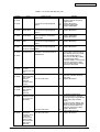
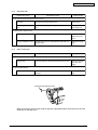
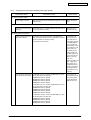
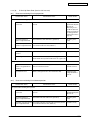
1.4
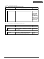
Specifications
Category
Item
C3300n
C3400n
Exterior
Width
372mm
Dimension
Depth
478mm
Height
290mm
Weight
about 21kg
A4
Width of print
Width of print
Engine
Monochrome
16ppm
20ppm
speed(A4)
Color 12ppm 16ppm
12ppm
16ppm
Fast print time
Monochrome
12sec
10sec
(A4)
Color
15sec
12sec
60sec
Warm-up time
Unavailable
Low noise mode
Resolution
600dpi
LED head
600 × 1200dpi
Maximum input resolution
Output resolution
Step
Economic mode
CPU
True 600 × 1200dpi
True 600 × 600dpi
4 steps 600 × 600dpi
toner saving by lowering light
Core
PowerPC405
I-cash
16KB
16KB
D-cash
200MHz
Clock
RAM
Bus width
32bit
Resident
32MB
Option
ROM
Program
Power
Power input
Consumption
Idle
Normal operation
Peak
In operation
Environment
(temperature)
At stand-by
In storage (1 year max.)
Operating
total capacity 2MB
100-127VAC (Range 99-140VAC) /
Below 14W
100W(average)
400W
980W
10°C-32°C,17°C-27°C
(temperature at full color printing with quality guaranteed)
0°C-43°C, power off
-10°C-43°C with drum and toner
At transport (1 month max.)
-29°C-50°C with drum and without toner
At transport (1 month max.)
-29°C-50°C with drum and toner
In operation
20%-80%, 50%-70%
(humidity at fullcolor printing with quality guaranteed)
Max. wet bulb temperature : 25°C
At stand-by
10%-90%, Max. wet bulb temperature : 26.8°Cwith power off
Environment
(humidity)
43163501TH Rev. 1
64/256MB DIMM
220-240VAC (Range 198-264VAC)
Power saving mode
Operating
Unavailable
In storage
10%-90%, Max. wet bulb temperature : 35°C
At transport
10%-90%, Max. wet bulb temperature : 40°C
11 /
Oki Data CONFIDENTIAL
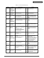
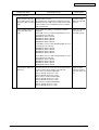
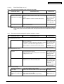
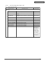
Category
Life
Item
C3300n
C3400n
300,000 pages or 5 years
Printer life
Duty cycle (M=L/12,A=L/12/5)
350,000 pages per month max.
5,000 pages per month average
6,000 hours
MTBF (2.3% duty)
35,000 pages
MTBF
20 minutes
MTTR
starter toner
(Appended)
ODA/JPN about 1,000 pages (black)
OEL/AOS about 500pages (black)
ODA/JPN about 1,000 pages (color)
OEL/AOS about 500pages (color)
Standard
about 2,500pages (black)
about 2,000pages (color)
New drum 1st one
about 1,700pages (black)
about 1,200pages (color)
S type
ODA about 1,500pages (black)
OEL/AOS/JPN about 1,000pages (black)
about 1,000pages (color)
Toner life
(5% duty)
New drum 1st one
ODA about 700pages (black)
OEL/AOS/JPN about 500pages (black)
about 500pages (color)
mage drum life
Transcript belt life
Fuser life
Operation
noise
In operation (ISO 7779 front)
Printing on one side
At stand-by (ISO 7779 front)
Power saving mode
Paper handling Paper feeding capacity (1st tray)
Paper feeding capacity
(manual feeder)
Paper output
Paper size
Legal/universal or A4 cassette/
Universal cassette
Manual feeder
Min. paper size 1st tray
Manual feeder
43163501TH Rev. 1
15,000 pages approx.(3 pages/ job)
9,000 pages approx.(1 page/ job)
20,000 pages approx.(at continuous print)
Automatic drum counter reset
50,000pages (size A4, 3 pages/job) Automatic counter reset
30,000pages (size A4)
50,000pages (size A4)
Automatic counter reset
Automatic counter reset
6.38B (A)
6.5B (A)
3.7B (A)
back grand level
legal/universal cassette 250 sheets (70kg)
1 sheet
150 sheets (70kg) face down/
one sheet (10 postcards) face up tray
1st cassette: legal13/13.5/14, letter, executive, A4, A5, B5,
A6, postcard
legal 13/13.5/14, letter,
legal 13/13.5/14, letter,
executive, A4, A5, B5, A6,
executive, A4, A5, B5, A6, C5,
C5, DL, Com-9, com-10,
DL, Com-9, com-10,monarch,
monarch, custom size,
custom size, , government
government postcard, reply postcard, reply paid postcard,
paid postcard, end-opening
end-opening envelope,
envelope
banner up to 1200mm (In
case length is over 356, width
would be up to 210 to 215.9)
100mm × 148mm
100mm × 148mm
12 /
Oki Data CONFIDENTIAL
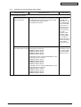
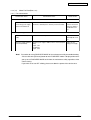
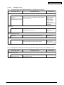
Category
Item
C3300n
C3400n
Paper
1st tray
64-120gsm
thickness
Manual feeder
64-203gsm
duplex (manual)
64-105gsm
3 (Green × 1, dark amber × 2)
Operation
LED (color)
panel
Switch
Status
Paper tray empty
switch/Sensor
Paper low
N/A
Toner low
Available (Y.M.C.K)
2
Available
Cover open
Available
Fuser temp.
Available
N/A
Paper size
N/A
Stacker full
Communication Standard (on circuit board)
¥ Full-Speed USB
Ethernet
Interface
N/A
Option for OEM user
Automatic
On/off switch
Emulation
Font
Hiper-C
Standard
Emulation switch
N/A
Bit map
Type face
N/A
Scalable 1
Type face
N/A
Scalable 2
Type face
N/A
Scalable 3
Type face
N/A
Luster riser
N/A
Bar code
N/A
OCR
N/A
Japanese PCL font
N/A
Japanese PS font
N/A
Option
(Removable)
RAM set
Shipping setup
Japan
Others
USB-IF logo
Windows logo
Operation by UPS
43163501TH Rev. 1
Hi-Speed USB
N/A
64, 256MB
GDI model
Available
Available
Operation by UPS (outage free power supply) is not
guaranteed. (Do not use UPS)
13 /
Oki Data CONFIDENTIAL
1.5 Interface Specification
1.5.1 USB Interface Specification (C3400n)
1.5.1.1 Outline of USB Interface
(1) Basic Specification
USB (C3400n supports Hi-Speed USB)
(2) Transmission Mode
Full speed (12Mbps±0.25% max.)
Hi speed (480Mbps±0.05% max.)
(3) Power Control
Self power device
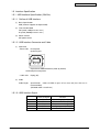
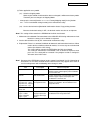
1.5.1.2 USB Interface Connector and Cable
(1) Connector
• Printer side:
B receptacle
Upstream port
2
1
3
4
Equivalent of UBR24-4K5C00 (made by ACON)
Connector pin arrangement
• Cable side:
B plug (off)
(2) Cable
Cable length:
Specification
Cable of USB2.0 spec. of less than 5m.(less than 2m is
recommended)
(Shielded cable is used here.)
1.5.1.3 UBS Interface Signal
1
2
3
4
Shell
43163501TH Rev. 1
Name of Signal
Vbus
DD+
GND
Shield
Function
Power Supply (+5V) (red)
Data transmission (white)
Data transmission (green)
Signal ground (black)
14 /
Oki Data CONFIDENTIAL
1.5.2 Network Interface Specification (C3400n)
1.5.2.1 Outline of Network Interface
Table1.5.2 Basic Specification of Network Interface (C3400n
Protocol Family
Network Protocol
Application
TCP/IP
IPv4,TCP,ICMP,UDP
LPR,RAW
SNMPv1
DHCP/BOOTP
HTTP
1.5.2.2 Network Interface Connector and Cable
(1) Connector
100 BASE-TX/10 BASE-T (automatic switch, no simultaneous use)
1
8
Connector pin arrangement
(2) Cable
Unshielded twist pair cable with RJ-45 connector (Category 5 is recommended.)
1.5.2.3 Network Interface Signal
43163501TH Rev. 1
Pin No.
Signals
Signal Direction
Functions
1
TXD+
FROM PRINTER
Send Data +
2
TXD-
FROM PRINTER
Send Data -
3
RXD+
TO PRINTER
Received Data +
4
-
-
Unassigned
5
-
-
Unassigned
6
RXD-
TO PRINTER
Received Data -
7
-
-
Unassigned
8
-
-
Unassigned
15 /
Oki Data CONFIDENTIAL
2.
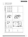
OPERATION DESCRIPTION
2.1
Electrophotographic Process Mechanism
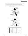
(1) Electronic photography Process
Electronic photography process is outlined as follows:
1. Electrification
Electric voltage is impressed on CH roller and the surface of CPC drum is electrified.
2. Exposure
LED head radiates light on the electrified surface of OPC drum following the image
signal. Electric charge on the radiated OPC drum surface abates depending on the
intensity of light and static latent image is formed on the OPC drum surface.
3. Development
Electrified toner is adhered to the static latent image on the OPC drum by static electricity and a visible image is formed on the OPC drum surface.
4. Transcript
A sheet of paper is put upon the OPC drum surface and the toner image is transferred
on the paper by impressing electric charge on its back side by the transcript roller.
5. Drum Cleaning
Drum cleaning blade eliminates the remaining toner on the OPC drum after transfer.
6. Belt Cleaning
Belt cleaning blade eliminates the remaining toner on the belt.
7. Fusing
The toner image on the paper is fused by adding heat and pressure.
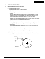
(2) Electrification
Electric voltage is impressed on electrification roller touching on the OPC drum surface and
thus the OPC drum surface is electrified.
Electrification roller
Power
supply
unit
---
OPC drum
43163501TH Rev. 1
16 /
Oki Data CONFIDENTIAL
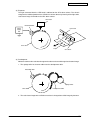
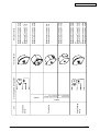
(3) Exposure
The light emanated from the LED head is radiated on the OPC drum surface. The electric
charge on the radiated portion of the OPC drum surface abates by intensity of the light and a
static latent image is formed on the OPC drum surface.
LED head
Electrified roller
Power
supply
unit
LED head
-- -
- -
OPC drum
Paper
OPC drum
(4) Development
Adhere the toner to the static latent image on the drum surface and change it to the toner image.
1. The sponge roller let the toner adhere to the development roller.
Electrified roller
---
- -
OPC drum
Sponge roller
Development roller
2. The static latent image on the OPC drum surface is changed to a visible image by the toner.
43163501TH Rev. 1
17 /
Oki Data CONFIDENTIAL
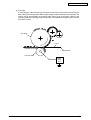
(5) Transcript
A sheet of paper is placed under the OPC drum surface and is given electric charge from the
back side by the transcript roller. When a high voltage is impressed on the transcript roller, the
electric charge generated by the transcript roller moves over to the paper surface at the
interfacing part of the transcript roller and the toner is absorbed to the paper surface from the
OPC drum surface.
--
---
- -
OPC drum
-
Paper
-+ -+-+ -+-+ -+ -+ -+ -+ -+-+ -+
-+
-+
+
+
-+
Transport belt
Transcript roller
Power
supply
unit
43163501TH Rev. 1
18 /
Oki Data CONFIDENTIAL
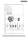
(6) Fusing
The toner image transferred on the paper is impressed with heat and pressure and is fused to
the paper when the paper passes through the heat roller and the back-up roller.
Further, a thermostat is equipped for the safety’s sake and if the temperature of the heat roller
rises above a certain degree, the thermostat opens and shuts the power supply to the heater.
C3400 (belt fusing method)
Thermostat
Thermistor
Halogen lamp
Heat roller
Paper
Pad
Backup roller
Thermistor
Belt
C3300 (roller fusing method)
Thermostat
Thermistor
Halogen lamp
Heat roller
Paper
Thermistor
Backup roller
Setting of Fusing Temperature
Paper Thickness Paper Type Setting
Thin
Thick
43163501TH Rev. 1
Temperature Setting
Light
Middle temp.
Medium
High temp.
Heavy
Middle temp.
U.Heavy
Low temp.
19 /
Oki Data CONFIDENTIAL
(7) Drum Cleaning
The toner not transferred and remaining on the OPC drum is scraped away by the drum
cleaning blade and is collected in the waste toner area of the toner cartridge.
Waste toner area
Toner cartridge
ID unit
Drum cleaning blade
(8) Belt Cleaning
The toner remaining on the transcript belt is scraped away by the belt cleaning blade and is
collected in the waste toner box of the transcript belt unit.
Transport belt
Belt waste toner box
Belt cleaning blade
43163501TH Rev. 1
20 /
Oki Data CONFIDENTIAL
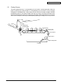
2.2
Printing Process
The paper feeded from tray 1 is transported by the resist roller L and transport roller. When the
paper is feeded by the manual feeder, it is transported by the resist roller U. Then, the paper
transported is developed into a toner image not yet fused on the paper through electronic
photography process in the order of KYMC. After that, the image is fused by heat and pressure
while passing through the fusing unit. After fusing, the paper is discharged on the face up or face
down stacker through the discharge method opted by opening or shutting of the face up stacker.
r
n stacke
w
Face do
Fac
e
Heat roller
up
Halogen lamp
sta
cke
r
Backup roller
Transport belt
Manual feeder
Resist roller U
Belt
Resist roller L
Paper feeding roller
Sub roller
43163501TH Rev. 1
21 /
Oki Data CONFIDENTIAL
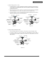
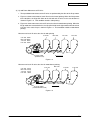
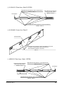
(1) Paper Feeding from the 1st Tray
1. As shown in Figure 2-1, while the solenoid is on and the resist motor turns counterclockwise,
a sheet of paper is transported until the IN1 sensor is on. (When the solenoid is on, the paper
feeding roller operates.)
2. When the paper turns the IN1 sensor on, a certain more sheets of paper are transported
and thrusted against the resist roller. (This process corrects the paper skew.)
3. As shown in Figure 2-2, turn the solenoid off and transport the paper by the resist roller L.
(When the solenoid is off, the resist roller operates.)
WR sensor
WR sensor
IN2 sensor
Resist roller U
(drive)
Resist roller L
(stop)
Hopping motor
(counterclockwise turn)
Resist roller L
(drive)
Hopping motor
(counterclockwise turn)
IN1 sensor
Solenoid lever
(solenoid on)
Sub roller
(drive)
Resist roller U
(drive)
IN2 sensor
Hopping roller
(drive)
IN1 sensor
Solenoid lever
(solenoid off)
Sub roller
(stop)
Paper
Figure 2-1
Hopping roller
(stop)
Paper
Figure 2-2
(2) Paper Feeding from Manual Feeder
1. Thrust the paper against the resist roller U. (This process corrects the paper skew.)
2. As shown in Figure 2-3, the resist motor turns counterclockwise and the paper is
transported by the resist roller U. (When the resist roller turns counterclockwise, the resist
roller U drives.)
WR sensor
IN 2 sensor
Paper
Resist roller U
(drive)
Resist roller L
(drive)
Hopping motor
(counterclockwise turn)
IN 1 sensor
Solenoid lever
(solenoid off)
Hopping roller
(stop)
Sub roller
(stop)
Figure 2-3
43163501TH Rev. 1
22 /
Oki Data CONFIDENTIAL
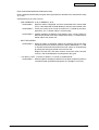
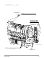
(3) Transport Belt
1. When the transport belt motor turns in the direction of the arrow, the transport belt starts
to operate. The belt unit is composed of drums of each color above and the transport rollers
immediately below them with the transport belt in-between. When a certain voltage is
impressed, the transport belt and the transport rollers send the paper on the transport belt
to the fuser while transferring the toner images on the drums of each color.
Drums
Transport belt
K
Y
M
C
Transport rollers
Transport belt motor
Figure 2-4
43163501TH Rev. 1
23 /
Oki Data CONFIDENTIAL
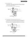
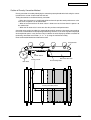
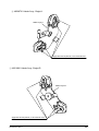
(4) Up and Down Movements of ID Units
1. The up and down movements of the ID units are performed by the drive of the lift-up motor.
2. Figure 2-5 shows movements of each ID unit at the time of printing. When the lift-up motor
turns clockwise, the lift-up link slides to the left and each ID unit is in the state of down as
shown in Figure 2-6. That condition enables color printing.
3. Figure 2-6 shows movements of each ID unit at the time of monochrome printing. When the
lift-up motor turns counterclockwise, the lift-up link slides to the right and the units other than
K-ID are in the state of up as shown in Figure 2-7. That condition enables monochrome
printing.
Movement of each ID unit at the time of color printing
C-ID unit
C-ID unit
M-ID unit
Y-ID unit
K-ID unit
M-ID unit
Y-ID unit
K-ID unit
down
down
down
down
Lift-up motor
(clockwise turn)
Figure 2-5
Movement of each ID unit at the time of monochrome printing
C-ID unit
C-ID unit
M-ID unit
Y-ID unit
K-ID unit
lift-up
lift-up
lift-up
down
M-ID unit
Y-ID unit
K-ID unit
Lift-up motor
(counterclockwise turn)
Figure 2-6
43163501TH Rev. 1
24 /
Oki Data CONFIDENTIAL
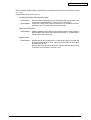
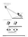
(5) Fusing Unit and Paper Output
1. As shown in Figure 2-7, the fuser unit and output roller are driven by the pulse motor. When
the fuser motor turns counterclockwise, the heat roller turns. This roller fuses the toner
image ‘on the paper with heat and pressure.
2. At the same time, the output roller turns and ‘sends out the paper.
Output roller
(drive)
Fuser unit
Heat roller (drive)
Fuser motor
(counterclockwise turn)
Figure 2-7
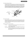
(6) Cover Open Operation of Color Registration Sensor and Density Sensor
1. As shown in Figure 2-8, when the fuser motor turns clockwise, the cover open gear also
turns and the covers of the color registration sensor and the density sensor will open.
2. When the fuser motor turns counterclockwise, interlocking of the cover open gear is
released and the covers of the color registration sensor and the density sensor will close.
Output roller
(stop)
Fuser unit
Heat roller (stop)
Cover open gear
Fuser motor
(clockwise turn)
Figure 2-8
43163501TH Rev. 1
25 /
Oki Data CONFIDENTIAL
Outline of Color registration Method
Color registration is performed by reading the correction pattern printed on the belt using the sensor
placed in the sensor shutter equipped under the belt unit. The correction is made by identifying the
pattern using this sensor.
Timing of automatic activation of color registration:
• At the time of switching the power on
• At the time of closing the cover after opening it over 5 seconds
• When over 400 sheets are printed after a color registration was made previously
Correction errors can be caused by the amount of toner which generates the pattern, toner stain
on the sensor, malfunction of shutter opening and closing. However, as an error may not be
displayed on the operation panel, it may be necessary to confirm the error display by forcible
execution of the color registration test function (2.4.1.5.3) using the maintenance utility.
Transport belt
Sensor shutter
Belt waste toner box
Color Registration sensor
Belt cleaning blade
Belt motor
Color Registration sensor
Right color registration pattern
Left color registration pattern
Color Registration sensor
43163501TH Rev. 1
26 /
Oki Data CONFIDENTIAL
Error Confirmation Method and Countermeasure
Errors should be confirmed by using the color registration test function of the maintenance utility
(2.4.1.5.3).
Countermeasures to each error are:
• SNS CARIBRAT(L or R), D-RANGEL(L or R)
•
Confirmation 1
When the above is displayed, check the connection of the sensor cable
(FFC). If the connection is found abnormal, correct it to the normal state.
Confirmation 2
Check the surface of the sensor to confirm if it is stained by the toner,
paper dust, etc. If stained, wipe the surface neatly.
Confirmation 3
Confirm adequacy of opening and shutting of the sensor shutter by
MOTOR& CLUTCH TEST of the maintenance utility. If a malfunction is
found, replace the shutter unit .
BELT REFLXERRR
Confirmation 4
•
When the above is displayed, confirm the cleaning state of the toner
remaining on the belt surface besides the above confirmations 1, 2 and
3. Remove the belt unit and confirm if the belt surface is cleaned neatly
by turning the drive gear placed in the left rear side.
Replace the belt unit if the toner remains on the belt surface and the
surface is not cleaned despite of turning of the drive gear.
(Y or M or C) LEFT. (Y or M or C) RIGHT, (Y or M or C) HORIZONTAL
Confirmation 5
43163501TH Rev. 1
When the above is displayed, confirm if it is the toner insufficiency that has
caused NG color generation and replace the cartridge if necessary.
27 /
Oki Data CONFIDENTIAL
Outline of Density Correction Method
Density correction is made by identifying the correction pattern printed on the belt using the sensor
installed in the sensor shutter under the belt unit.
Timing of automatic activation of density correction
• When the circumstance is significantly different from the previous work performance at the
time when the power is to be switched on.
• When at least one of the 4 ID count values is almost new at the time when the power is to
be switched on.
• When the ID count value is over 500 after the previous work performance.
Correction error can be caused by the amount of toner which generates the pattern, toner stain on
the sensor, malfunction of shutter opening and closing. However, as an error may not be displayed
on the operation panel, it may be necessary to confirm the error display by forcible execution of
the density correction test function (2. 4. 1. 5. 3) using the maintenance utility.
Error Confirmation Method and Countermeasure
Transport belt
Sensor shutter
Density sensor
Belt waste toner box
Belt cleaning blade
Belt motor
Density correction pattern
43163501TH Rev. 1
28 /
Oki Data CONFIDENTIAL
Errors should be confirmed by using the density correction test function of the maintenance utility
(2.4.1.5.4).
Countermeasures to each error are:
•
CALIBRATION ERR, DENS SENSOR ERR
Confirmation 1
Confirmation 2
•
DENS SHUTTER ERR
Confirmation 3
•
When the above is displayed, check connection of the sensor cable. If the
connection is found abnormal, correct it to the normal state.
Check the surface of the sensor to confirm if it is stained by the toner,
paper dust, etc. If stained, wipe the surface neatly.
Confirm adequacy of the opening and shutting of the sensor shutter by
MOTOR&CLUTCH TEST of the maintenance utility. If a malfunction is
found, replace the shutter unit.
DENS ID ERR
Confirmation 4
43163501TH Rev. 1
Remove the ID unit to confirm if the surface of the drum is covered with
abnormal amount of toner. Then, replace the LED head if the focus blurs
or replace the ID unit.
When a new ID unit is to be used for trial, attach a treatment device to the
ID unit lest the fuse breaks ( refer to p.132).
29 /
Oki Data CONFIDENTIAL
Toner Sensor Detection Principle
Detection of the low toner is performed by the toner sensor (light reception sensor) installed inside
the equipment and the luminous LED installed inside the cartridge. The shading board is installed
inside the ID and rotates synchronizing with the toner stir. A shutter is attached to the ID. The
shutter synchronizes with the cartridge operation lever and the toner sensor can detect whether
the cartridge is installed properly. If the toner sensor is stained by the toner, etc., or the ID unit and
the toner sensor are not facing each other as specified due to improper setting of the ID unit or for
other reason, the detection may not be executed normally, resulting in a toner sensor error.
Toner cartridge lever
Toner sensor
(light reception sensor)
Luminous LED
Toner stir
Shading board
Shutter
Toner Counter Principle
After the image data is developed into 2 value data to enable printing using the printer, the print
dot number is counted by the LSI. The amount of the toner used is counted from the above count
value and the remaining amount is displayed. On the other hand, detection of the low toner by the
toner sensor is physically made when the amount of the toner remaining in the cartridge comes
to be under certain amount.
Principles of ID, Belt and Fusing Counter
ID Counter
: 1 count is the value of one third of the amount of drum rotation when three A4
sheets of paper are continuously printed.
Belt Counter
: 1 count is one third of the amount of the belt rotation when three A4 sheets of
paper are continuously printed.
Fusing Counter : Standard is the length of Legal 13 inches sheet of paper. 1 count is the sheet of
paper under that length and when the length is more than that, the number of
count is decided by multiples of Legal 13 inches.(Number under the decimal
point is rounded up.)
43163501TH Rev. 1
30 /
Oki Data CONFIDENTIAL
3.
PRINTER INSTALLATION
3.1
Precautions and Prohibition
•
•
•
•
•
•
•
•
•
•
•
•
•
•
•
•
•
•
•
Do not install the printer in the vicinity of high temperature or fire.
Do not install the printer at the place where a chemical reaction may take place (laboratory, etc.).
Do not install the printer near flammable solution like alcohol, thinner, etc.
Do not install the printer at the place where a small child can reach.
Do not install the printer at an unstable place (unsteady frame, tilted place, etc.).
Do not install the printer at a highly humid or dusty place or under the direct sunshine.
Do not install the printer under the environment of sea breeze or caustic gas.
Do not install the printer at a highly vibrating place.
When you drop the printer or damage the cover, remove the power plug from the outlet and contact
the Customers’ Service Center.
Electric shock, fire or injury may occur.
Do not connect the power cord, printer cable and earth wire as otherwise directed by the Manual.
A fire may break out.
Do not insert a thing in the vent hole.
Electric shock, fire or injury may occur.
Do not place a cup with water on the printer.
Electric shock or fire may occur
Do not touch the fuser unit when you open the printer cover.
Burn may occur.
Do not throw the toner cartridge or image drum cartridge into fire.
Burn may occur by the dust explosion.
Do not use a highly flammable spray near the printer.
Fire may break out as there are high temperature parts inside the printer.
When the cover becomes abnormally hot, a smoke arises or a strange odor comes out, remove
the power plug from the outlet and contact the Customers’ Service Center.
Fire may break out.
When liquid like water drops inside the printer, remove the power plug from the outlet and contact
the Customers’ Service Center.
Fire may break out.
When a thing like a clip drops inside the printer, remove the power plug from the outlet and take
out that thing.
Do not operate or disassemble the printer as otherwise directed in the Manual.
Electric shock, fire or injury may occur.
43163501TH Rev. 1
31 /
Oki Data CONFIDENTIAL
• Do not install the printer at the place where the vent hole is blocked.
• Do not install the printer on the shaggy carpet.
• Do not install the printer at the place with little draught or without ventilation like a room with no
window.
• Install the printer away from the monitor TV.
• When the printer is to be moved, hold both ends of the printer.
• This printer weighs about 21kg and should be lifted by 2 or more persons.
• When to switch the power on or while printing, do not come near the paper exit of the printer.
Injury may occur.
As regards the items of caution, explain to the customer showing the items of caution of the User’s
Manual. Particularly, explain fully about the power supply cord and earth cable.
43163501TH Rev. 1
32 /
Oki Data CONFIDENTIAL
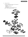
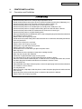
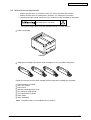
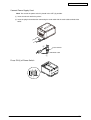
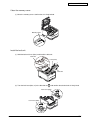
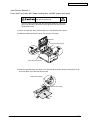
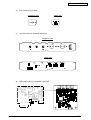
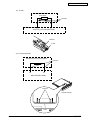
3.2
Printer Unpacking Procedure
Personal injuries may occur.
This printer weighs about 21kg. So lift it up with 2 or more persons.
•
•
•
•
Open the upper lid.
Take out accessories.
Remove the upper buffer material.
Take out the equipment
43163501TH Rev. 1
33 /
Oki Data CONFIDENTIAL
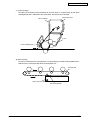
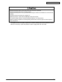
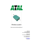
3.3 Printer Installation Instructions
• Install the printer at a place under the following temperature and humidity:
Ambient Temperature
: 10 to 32°C
Ambient Humidity
: 20 to 80% relative humidity
Maximum Wet-Bulb Temperature : 25°C
• Be careful not to be bedewed.
• When the printer is to be installed at a place where the humidity is less than 30%, use a humidifier
or a static electricity prevention mat.
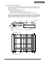
Installation Space
• Place the printer on a flat desk with enough space for the legs of the printer.
• Secure enough space around the printer.
Top View
20cm
30cm
100cm
20cm
Side View
50cm
43163501TH Rev. 1
34 /
Oki Data CONFIDENTIAL
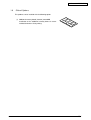
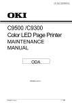
3.4 Packed Units and Attachments
• Confirm whether there are scratches, stains, etc. on the exterior of the machine.
• Confirm whether there are lacking items, damages, etc. among the accessories.
• If anything unusual is found, contact the user’s section in charge and follow its instruction.
Personal injuries may occur.
This printer weighs about 21kg and should be lifted by 2 or more persons.
■ Printer (main body)
C3400n
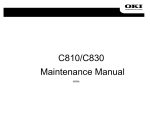
■ Image Drum Cartridges with Starter Toner Cartridges (4 sets) (installed in the printer)
Explain to customers that the toner cartridge and the image drum cartridge are separable.
■
■
■
■
■
■
■
■
Printer Software CD-ROM
LED Lens Cleaner
Power Cord
Warranty and Registration Card
Users Manual (Setup Guide)
Users Manual on CD-ROM
Quick Guide
Quick Guide Bag
Note! The printer cable is not included in the accessories.
43163501TH Rev. 1
35 /
Oki Data CONFIDENTIAL
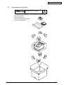
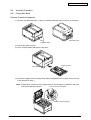
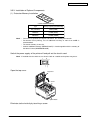
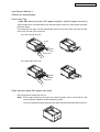
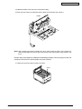
3.5
Assembly Procedure
3.5.1 Printer Main Body
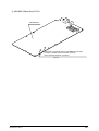
Remove Protective Equipment
(1) Remove front protection tapes (2 places) and back protection tapes (2 places) of the printer.
Protection tapes
Protection tapes
(2) Pull out the paper cassette.
(3) Press the open button and open the top cover.
Paper Cassette
Open Button
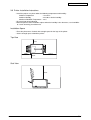
(4) Remove the stopper release (orange color) while pushing down the lever (blue) of the fuser unit
in the direction of arrow 1.
Note! Explain to the customer that the stopper release must be kept as it would be used at the
time of transporting the printer.
Lever of the fuser unit (blue)
Stopper release (orange)
43163501TH Rev. 1
36 /
Oki Data CONFIDENTIAL
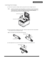
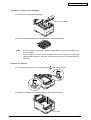
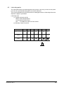
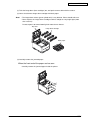
Install Image Drum Cartridges
(1) Pull out the image drum cartridge (4 pieces) gently with the toner cartridge attached.
Note! • Handle the image drum (green tube portion) very carefully as it is quite easily injured.
• Do not expose the image drum cartridge to direct sunshine or bright light (approximately
1,500 lux or more) . Do not leave it more than 5 minutes under the room light.
• Do not move the blue lever of the cartridge at this stage.
Starter Toner Cartridge
Image Drum Cartridge
(2) Place the image drum cartridge on a flat desk, remove the tape which fastens the protection
sheet and pull it out in the direction of arrow.
Note! Do not work on the image drum off the desk top.
Protection sheet
Tape
Protection sheet
(3) Pull out protection sheet 2 from the image drum cartridge in the direction of arrow.
Protection sheet
43163501TH Rev. 1
37 /
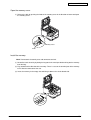
Oki Data CONFIDENTIAL
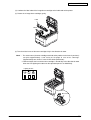
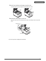
(4) Conform the label color of the image drum cartridge to the label color of the printer.
(5) Return the 4 image drum cartridges gently.
Label
Labels
(6) Turn the 4 blue levers of the toner cartridges fully in the direction of arrow.
Note! • The starter toner (the toner cartridge attached to the product at the time of purchase)
can print approximately 1,000 sheets of A4 paper in case of 5% coverage.
(Approximately 500 sheets in case of OEL/AOS specification)
• Confirm whether the lever of the toner cartridge is turned fully in the direction of arrow
when the LED lighting of no toner on the operation panel is on indefinitely.
Lighting of LED
Blue Lever
43163501TH Rev. 1
38 /
Oki Data CONFIDENTIAL
Load Paper in Paper Cassette
(1) Pull out the paper cassette.
Note! Do not remove the cork on the plate.
(2) Conform the paper guide to the paper size and fix it firmly.
Cork
Plate
Paper Guide
(3) Shuffle the sheets of paper and arrange up, down, left and right properly.
(4) Make the printable side down and set the paper.
Note! • Place the paper in front of the paper cartridge.
• Set the paper not to exceed “▼
▼ ”mark of the paper guide. (250 sheets weighing 70kg)
(5) Fix the paper by the paper stopper.
(6) Return the paper cassette to the printer.
Paper Stopper
Printing face down
Paper life display
43163501TH Rev. 1
39 /
Oki Data CONFIDENTIAL
Load Paper in the Manual Feed Opening
(1) Put a finger in the dent at the center of the manual feed opening and pull forward.
Manual Feed Opening
(2) Conform the manual feeding guide to the size of the paper.
(3) Arrange the left and right of the paper.
Manual Feeding Guide
Manual feeding opening
Manual Feeding Guide
(4) Make the printing side up and insert the paper straight to the rear end along the manual feed
guide.
43163501TH Rev. 1
40 /
Oki Data CONFIDENTIAL
Preserve the Quick Guide
Paste the quick guide case to the printer and put in the quick guide.
(1) Turn around the quick guide case and remove the covers of the Double faced adhesive tapes
(2 places).
Double faced adhesive tapes
(2) Paste the case to the printer.
Quick Guide
Quick Guide Bag
Note! Paste the case so as not to block the vent hole on the back of the printer.
43163501TH Rev. 1
41 /
Oki Data CONFIDENTIAL
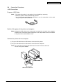
3.5.2 Power Cable Connection
Conditions for Power Supplies
• Observe the following conditions:
Alternate Current (AC) : 110 ~127VAC(Range 99~140VAC)/220 ~240VAC(Range
198~264VAC)
Power Supply Frequency : 50Hz or 60Hz±2%
• Use a voltage regulator when the power supply is not stable.
• The maximum power consumption of this printer is 980W. Confirm that the power supply has
sufficient extra capacity.
It may expose you to electric shocks or cause a fire.
• Never fail to switch off the power supply at the time of connection or removal of the electric cord
and earth cable.
• Always connect the earth cable to the earth terminal equipped only for that purpose. Never
connect the earth cable with water pipe, gas pipe, telephone cable earth terminal, lightening rod,
etc.
• Always grasp the power plug at the time of connection and removal of the electric cord.
• Always make sure that the electric plug is inserted fully into the outlet.
• Do not connect or disconnect the electric plug with the wet hand.
• Do not install the electric cord at the place liable to be stepped on and do not put things on the
electric cord.
• Do not bundle up or tie up the electric cord
• Do not use the damaged electric cord.
• Do not put many loads on one electric outlet.
• Do not connect this printer to the same outlet with other electric machines. Particularly, erroneous
operation may occur by electric noise when the same outlet is shared by the air conditioner,
duplicator, shredder, etc. at the same time. When the same outlet had to be used, use a noise filter
or noise cut transformer on the market.
• Use the attached electric cord only.
• Do not use an extension cord. Use the cord of over rating 15A if you had to use one.
• When you use the extension cord, the printer may not operate normally due to the drop of AC
voltage.
• Do not shut down the power supply or remove the power plug while printing.
• Disconnect the power cord when the printer would not be used for some long while due to
consecutive holidays or journey.
As to the connection of the electric cord and earth cable, explain fully to the customer showing the
User’s Manual.
43163501TH Rev. 1
42 /
Oki Data CONFIDENTIAL
Connect Power Supply Cord
Note! Be certain the power switch is placed in the OFF (O) position.
(1) Insert the electric cord in the printer.
(2) Insert the plug in the outlet after connecting the earth cable with the earth cable terminal of the
outlet.
2
Earth Terminal
Earth Cable
1
Press ON (I) of Power Switch
43163501TH Rev. 1
43 /
Oki Data CONFIDENTIAL
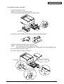
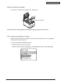
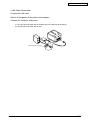
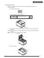
3.5.3 Installation of Optional Components
(1) Extension Memory Installation
C3400n Additional Memory
Type
Memory Capacity (Total Memory)
N/A (standard)
32MB (32MB)
MEM64D
+64MB (96MB)
MEM256D
+256MB (288MB)
Note! • You must use genuine Oki Original. Otherwise, the memory will not work.
• For banner-sheet printing, use of additional memory of more than 64MB is
recommended.
• The slot for memory is one slot.
• C3400n additional memory (MEM64D/256D) is interchangeable with the memory of
the former C5200 (MLMEM64B/256B).
Switch the power supply of the printer off and pull out the electric cord.
Note! If installed with the switch on, an electric shock or a trouble to the printer may occur.
I
Open the top cover.
O
Top cover
Screw
Open Button
Eliminate static electricity by touching a screw.
43163501TH Rev. 1
44 /
Oki Data CONFIDENTIAL
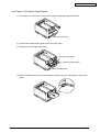
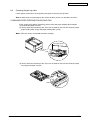
Remove the image drum cartridges.
(1) Remove the 4 image drum cartridges.
Image Drum Cartridge
(2) Cover the removed image drum cartridges with a sheet of black paper.
Note! • As the image drum (green tube portion) is quite liable to injury, take care fully at the
time of handling.
• Do not expose the image drum cartridge to the direct sunshine or bright light
(approximately more than 1,500 lux). Do not leave it more than 5 minutes under the
room light.
Remove the belt unit.
(1) Turn the lock levers (blue, 2) in the direction of
, and release the lock.
(2) Hold the lever (blue) of the belt unit and take out the belt unit gently.
Lever (blue)
43163501TH Rev. 1
45 /
Oki Data CONFIDENTIAL
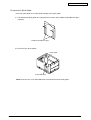
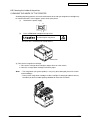
Open the memory cover.
(1) Release the lock by pushing the knob of the memory cover in the direction of arrow and open
the memory cover.
2
1
Memory Cover
Knob
Install the memory.
Note! Do not touch electronic parts and connector terminal.
(1) Neutralize static electricity by letting the bag touch the metal part before taking out the memory
from the bag.
(2) Pay attention to the direction of the memory. There is a cut on the terminal part of the memory
to fit it into the connector of the slot.
(3) Insert the memory in the empty slot and bring it down to the circuit board side.
43163501TH Rev. 1
46 /
Oki Data CONFIDENTIAL
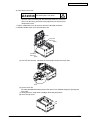
Close the memory cover.
(1) Close the memory cover. Confirm that it is firmly locked.
Memory Cover
Install the belt unit.
(1) Hold the belt unit lever (blue) and install the belt unit.
Belt Unit
Lever (blue)
Belt Unit
(2) Turn the lock lever(blue, 2) in the direction of
and confirm that the belt unit is firmly fixed.
Lock Lever (blue)
Lock Lever (blue)
43163501TH Rev. 1
47 /
Oki Data CONFIDENTIAL
Install the image drum cartridge.
(1) Restore the 4 image drum cartridges to the original place.
Image Drum Cartridge
Install the electric cord and printer cable to the printer and set the switch on.
3.5.4 Confirm the Recognition of Option
In order to confirm that the items of option are correctly installed, conduct the menu map printing
referring to “3.6 Status Page Print”.
(1) Confirm Recognition of Additional Memory
Confirm the contents of the status pages.
Confirm the total memory size displayed as “TOTAL MEMORY SIZE” in the header portion.
43163501TH Rev. 1
48 /
Oki Data CONFIDENTIAL
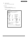
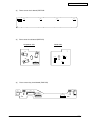
3.6
Status Page Print
Make sure that the printer operates normally.
For C3400n
(1) Set sheets of A4 paper in the tray
(2) Push the on-line switch for 2 seconds and release.
(Sample) In case of C3400n
43163501TH Rev. 1
49 /
Oki Data CONFIDENTIAL
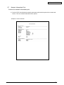
3.7
Network Information Print
Confirm the network information print.
(1) Push the TEST switch beside the network connector on the back of the printer for 5 seconds and
release. Then the network information will be printed.
(Sample) In case of C3400n
43163501TH Rev. 1
50 /
Oki Data CONFIDENTIAL
3.8
Connection Procedures
<USB Connection>
Prepare a USB Cable.
Note! • The cable of the printer is not attached. Users should buy seperately.
• Obtain the cable of USB specification by yourself.
• Use the USB cable of Hi-Speed specification in case the connection is to be made
using “HI-Speed” mode of USB2.0.
Switch off the power of the printer and computer.
Memo Although the USB cable can be connected or removed with the switch of the computer
and printer on, switch off the power of the printer at this step in order to ensure installation
of the printer driver and USB driver later.
Connect the printer with the computer.
(1) Plug the USB cable into the USB interface connector of the printer.
(2) Plug the USB cable into the USB interface connector of the computer.
Note! Be careful not to insert the USB cable into the network interface connector.
Or else it may cause troubles.
UBS Interface Connector
43163501TH Rev. 1
51 /
Oki Data CONFIDENTIAL
<LAN Cable Connection>
Prepare the LAN cable.
Switch off the power of the printer and computer.
Connect the computer and printer.
(1) Plug the Ethernet cable into the network interface connector of the printer.
(2) Plug the Ethernet cable into the hub.
Network Interface Connector
43163501TH Rev. 1
52 /
Oki Data CONFIDENTIAL
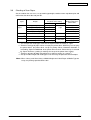
3.9
Checking of User Paper
Set the medium the user uses, set up media type/weight, conduct menu map/demo print and
confirm that the toner does not peel off.
Types
Weight
Media weight
Regular
paper*3
55-64kg (64-74g/m2)
65-89kg (75-104g/m )
Madium
2)
104-172kg (121-200g/m
Envelope*4
Label paper
Less than 0.1-0.17mm
0.17-0.2mm
Light
Madium
Light
Light
2
90-103kg (105-120g/m2)
Postcard*4
Media type *1
Setting *2 for
[Media weight] of the
printer driver
Setting values of
the printer menu setting
Heavy
Heavy
Ultra Heavy
Ultra Heavy
-
-
-
-
-
-
Heavy
Ultra Heavy
Label paper 1
Label paper
Label paper 2
*1
: The set-up of the media type at the time of shipment from the factory is “Light”.
: Thickness and type of paper can be set up by the printer driver. When they are set up by
the printer driver, the printer driver set-up has priority. When “Automatic Selection” is
selected by “Paper Feed Method” of the printer driver or when “Printer Set-up” is selected
by “Paper Thickness”, printing is made by the set-up of the printer menu setting.
*3 : Thickness of paper for both side printing is 65~90kg in weight (75~105g/m2).
*4 : Set-up of media weight and media type is not necessary for postcards and envelopes.
*2
Memo When “Heavy” and “Ultra Heavy” of Media Weight and “Label Paper” of Media Type are
set up, the printing speed becomes slow.
43163501TH Rev. 1
53 /
Oki Data CONFIDENTIAL
4.
REPLACEMENT OF PARTS
This section explains the field replacement procedures for parts, assemblies and component units.
While those replacement procedures refer to the disassembling of parts, follow the same
procedures inversely for reassembling them.
The part numbers (1, 2, etc.) employed in this manual are different from those assigned in the
corresponding configuration diagrams of Disassembly for Maintenance (43163501TL) and RSPL
(43163501TR).
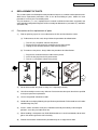
4.1
Precautions on the replacement of parts
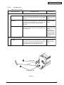
(1)
Prior to replacing a part, be sure to disconnect the AC cord and interface cable.
(a) To disconnect the AC cord, always follow the procedure described below:
1 Turn off ("O") the power switch of the printer.
2 Pull out the AC plug of the AC cord from the AC power outlet.
3 Unplug the AC cord and interface cable from the printer.
(b) To reconnect the printer, always follow the procedure described below:
1 Plug the AC cord and interface cable into the printer.
2 Insert the AC plug into the AC power outlet.
3 Turn on ("|") the power switch of the printer.
Disconnect
Connect
(2)
Do not disassemble the printer as long as it is operating normally.
(3)
Limit disassembly to a necessary minimum. Do not remove other parts than those specified
in the part replacement procedure.
(4)
Use the designated maintenance tools.
(5)
Conduct disassembly by following the specified sequential order. Failure to observe this order
could damage the parts.
(6)
Screws, collars and other small parts should be attached provisionally to their original
positions, since they are liable to be lost.
(7)
When handling a microprocessor, ROM, RAM and other ICs and circuit boards, do not wear
gloves that tend to generate static electricity.
(8)
Printed-circuit boards should not be placed directly on an equipment or floor.
43163501TH Rev.1
54 /
Oki Data CONFIDENTIAL
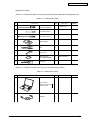
[Maintenance Tools]
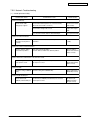
Clawle 4-1-1 indicates the tools necessary to replace printed-circuit boards and component units.
Clawle 4-1-1 Maintenance Tools
No.
Service Tools
Q' ty
1
No. 2-200 Philips
screwdriver, Magnetized
1
2
No. 3-100 screwdriver
1
3
No. 5-200 screwdriver
1
4
Digital multimeter
1
5
Pliers
1
6
Handy cleaner
1
7
LED Head cleaner
P/N 4PB4083-2248P001
1
8
E-ring pliers
1
Place of use
Remarks
3~5 mm screws
Cleans LED head
Clawle 4-1-2 indicates the tools necessary for using maintenance utilities.
Table 4-1-2 Maintenance Tools
No.
Service Tools
Q' ty
1
Laptop computer
Must have maintenance
utilities installed
1
2
USB cable
1
43163501TH Rev.1
Place of use
Remarks
55 /
Oki Data CONFIDENTIAL
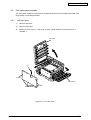
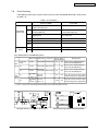
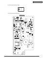
4.2
Part replacement methods
This subsection explains the replacement methods for the parts and assemblies illustrated in the
disassembly system diagram below.
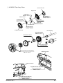
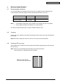
4.2.1
Left side cover
(1)
Open the top cover.
(2)
Open the front cover.
(3)
Remove a screw (silver) 1 four claws A and a claw B to detach the left side cover 2.
(Tool No. 1)
Top cover
1
ClawB
Front-cover
2
ClawA
Figure 4-2-1 Left side cover
43163501TH Rev.1
56 /
Oki Data CONFIDENTIAL
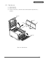
4.2.2
Right side cover
(1)
Open the top cover.
(2)
Open the front cover.
(3)
Take out a screw (silver) 1 four claws A and a claw B to detach the right side cover 2.
(Tool No.1)
Top cover
1
2
ClawB
ClawA
Front-cover
Figure 4-2-2 Right side cover
43163501TH Rev.1
57 /
Oki Data CONFIDENTIAL
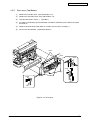
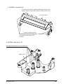
4.2.3
Rear cover (Top/Bottom)
(1)
Remove the left side cover. (See Subsection 4.2.1)
(2)
Remove the right side cover. (See Subsection 4.2.2)
(3)
Take out two screws (silver) 1. (Tool No.1)
(4)
As shown in the drawing, put the flat-blade screwdriver (Tool No.3) into a hole A to remove
two claws A.
(5)
Remove tow claws B by hand and then, remove the rear cover assembly 2.
(6)
Lift the rear cover bottom 3 upward to detach it.
ClawA
2
HoleA
HoleA
HoleA
ClawA
1
3
ClawB
HoleA
Hole
Figure 4-2-3 Rear cover
43163501TH Rev.1
58 /
Oki Data CONFIDENTIAL
4.2.4
Front cover
(1)
Remove the Shaft-Cover 1 and the stay 2 and then, remove the Shaft-Cover 3, and the
Front-Cover 4.
4
2
1
3
Figure 4-2-4 Front cover
43163501TH Rev.1
59 /
Oki Data CONFIDENTIAL
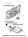
4.2.5
Top cover assembly
(1)
Open the top cover.
(2)
Remove the left side cover. (See Subsection 4.2.1)
(3)
Remove the right side cover. (See Subsection 4.2.2)
(4)
Detach the rear cover. (See Subsection 4.2.3)
(5)
Remove the plate heat. (See Subsection 4.2.18)
(6)
Remove the plate shield front. (See Subsection 4.2.16)
(7)
Take out a screw (silver) 1.
(8)
Remove the BLA-PCB (main board) (See Subsection 4.2.23), and then, remove the head
cable (FFC) and the RFID cable.
(9)
Remove two E-type retaining rings 2 two sprint torsions 3 and the top cover assembly 4.
4
3
ViewA
2
3
1
2
4
Head cable(FFC)
BLA-PCB
(Main circuit board PCB)
K
Y
M
C
RFID
ViewA
1
Figure 4-2-5 Top cover assembly
43163501TH Rev.1
60 /
Oki Data CONFIDENTIAL
4.2.6
Top cover
(1)
Remove the top cover assembly. (See Subsection 4.2.5)
(2)
Take out nine screws (black) 1 to remove the top cover 2.
2
1× 9
Figure 4-2-6 Top cover
43163501TH Rev.1
61 /
Oki Data CONFIDENTIAL
4.2.7
LED assembly/ LED assembly spring
(1)
Open the top cover.
(2)
After removing the head cable (FFC), apply force in the direction of the arrow ‘X’ as shown
in Figure (2). Remove a hook A first and then a hook B to remove the LED assembly 1.
(3)
Remove the LED assembly SU spring 2.
Top cover
2
Hook A
X
1
Figure(2)
Hook B
Figure(1)
Figure 4-2-7 LED assembly/ LED assembly spring
43163501TH Rev.1
62 /
Oki Data CONFIDENTIAL
4.2.8
RFID assembly
(1)
Remove the top cover assembly. (See Subsection 4.2.6)
(2)
Remove the top cover. (See Subsection 4.2.7)
(3)
Remove two screws (silver) 1 and all connectors to detach the LUM board (RFID reader
writer) 2.
(4)
Detach six claws A and two claws B engaging with the plate-inner 3 to remove RFID
assembly 4.
1
2
3
4
Claw A
Claw B
Figure 4-2-8 RFID assembly
43163501TH Rev.1
63 /
Oki Data CONFIDENTIAL
4.2.9
Control pane assembly
(1)
Open the top cover.
(2)
Open the front cover.
(3)
Remove the right side cover (See Subsection 4.2.2)
(4)
Remove the plate shield front and cable (See Subsection 4.2.16)
(5)
Detach FFC which connects the control panel assembly with the control panel PCB.
(6)
Take out four screws (silver) 1 to remove the control panel assembly 2. (Tool No.1)
1
2
1
OP cable
Figure 4-2-9 Control pane assembly
43163501TH Rev.1
64 /
Oki Data CONFIDENTIAL
4.2.10 WHI board
(1)
Remove the control panel assembly (See Subsection 4.2.9)
(2)
Take out a claw A to remove the frame OP 1.
(3)
Remove a claw B and the button lock 2 to detach the lever lock 3.
(4)
Remove a spring 4.
(5)
Remove four claws C and the cover assembly OP 5. to remove the WHI board (operation
panel) 6.
(6)
Remove a spring 7.
Claw A
Claw C
1
6
5
7
Claw C
Claw B
2
3
Claw B
4
Claw A
Figure 4-2-10 WHI board
43163501TH Rev.1
65 /
Oki Data CONFIDENTIAL
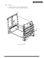
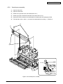
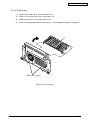
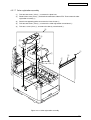
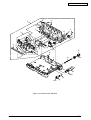
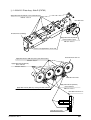
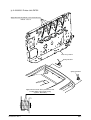
4.2.11 Feeder unit
(1)
Open the top cover.
(2)
Open the front cover. (See Subsection 4.2.4)
(3)
Remove the Lever_Lock_Assembly 1.
(4)
Remove the left side cover. (See Subsection 4.2.1)
(5)
Remove the right side cover. (See subsection 4.2.2)
(6)
Detach the plate shield front. (See Subsection 4.2.16)
(7)
Remove a connector 3 connecting to the feeder unit 2 from the BLA board (main board).
(8)
Take out four screws (silver) 4 to remove the feeder unit 2.
(9)
Remove claws to remove the cover sensor 5.
(10) Remove the MIP board (front sensor board) 6.
HOP
3
5
6
BLA-PCB (Main circuit board PCB)
3
4×4
1
BLA-PCB
(Main circuit board PCB)
2
Figure 4-2-11 Feeder unit
43163501TH Rev.1
66 /
Oki Data CONFIDENTIAL
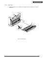
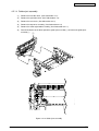
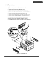
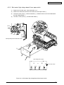
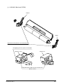
4.2.12 Manual feeder unit
(1)
Open the top cover.
(2)
Open the manual feeder 1 .
(3)
Hold both ends of the manual feeder 1 and pull it in the direction of the arrow to remove it.
1
about 45°
Figure 4-2-12 Manual feeder unit
43163501TH Rev.1
67 /
Oki Data CONFIDENTIAL
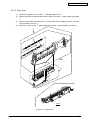
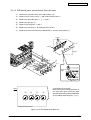
4.2.13 Face up tray
(1)
Remove the left side cover. (See Subsection 4.2.1)
(2)
Remove the right side cover. (See Subsection 4.2.2)
(3)
Remove the rear cover. (See Subsection 4.2.3)
(4)
Remove the supporting points of the face up tray 1 with a flat blade screwdriver. (Tool No.3)
1
Support point (2 places)
Figure 4-2-13 Face up tray
43163501TH Rev.1
68 /
Oki Data CONFIDENTIAL
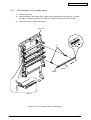
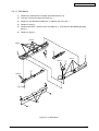
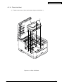
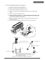
4.2.14 Guide eject assembly
(1)
Remove the left side cover. (See Subsection 4.2.1)
(2)
Remove the right side cover. (See Subsection 4.2.2)
(3)
Remove the rear cover. (See Subsection 4.2.3)
(4)
Remove the top cover assembly. (See Subsection 4.2.5)
(5)
Remove the color registration assembly. (See Subsection 4.2.17)
(6)
Detach two latches at the lower part of the guide eject assembly 1 to remove the guide eject
assembly 1.
1
Latche
Figure 4-2-14 Guide eject assembly
43163501TH Rev.1
69 /
Oki Data CONFIDENTIAL
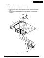
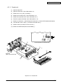
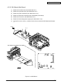
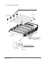
4.2.15 Eject roller
(1)
Remover the guide eject assembly 1. (See Subsection 4.2.14)
(2)
Remove two claws A to divide them into the guide eject lower 2 and the guide eject upper
3.
(3)
Detach a claw B, three gear idle ejects 4. Remove the shaft assembly eject (FD) 5 and the
shaft assembly eject (FU) 6.
(4)
Remove the eject sensor 7, and the lever eject sensor 8 from the guide eject lower 2.
1
5
4
6
claws B
3
Claws A
2
8
7
View A
View A
Figure 4-2-15 Eject roller
43163501TH Rev.1
70 /
Oki Data CONFIDENTIAL
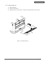
4.2.16 Plate shield front
(1)
Remove two screws (silver) and remove the plate shield front 2.
2
1
claws
Figure 4-2-16 Plate shield front
43163501TH Rev.1
71 /
Oki Data CONFIDENTIAL
4.2.17 Color registration assembly
(1)
Take out two screws (silver) 1 to remove the plate heat.
(2)
Remove two screws (silver) 3 to detach two connectors and one FFC. Then remove the color
registration assembly 4.
(3)
Detach two supporting points to remove the frame shutter 5.
(4)
Take out two screws (silver) 6 to remove the color registration sensor board 7.
(5)
Take out a screw (silver) 8 to remove the density sensor board 9.
4
3
5
Fulcrums
3
9
8
1
7
2
1
6
Figure 4-2-17 Color registration assembly
43163501TH Rev.1
72 /
Oki Data CONFIDENTIAL
4.2.18 Plate shield rear
(1)
Remove the left side cover. (See Subsection 4.2.1)
(2)
Remove the right side cover. (See Subsection 4.2.2)
(3)
Remove the rear cover. (See Subsection 4.2.3)
(4)
Remove the top cover assembly. (See Subsection 4.2.5)
(5)
Remove the color registration assembly. (See Subsection 4.2.17)
(6)
Remove the plate shield front. (See Subsection 4.2.16)
(7)
Remove the low voltage power supply. (See Subsection 4.2.22)
(8)
Remove the BLA board (main board.) (See Subsection 4.2.23)
(9)
Takeout two screws (silver) 1 to remove the plate heat 2.
(10) Remove latches of the gear lift up 3 to detach a shaft 4.
(11) Take out three screws (silver) 5 to remove the plate shield rear 6.
1
1
2
5
5
6
4
3
3
5
Figure 4-2-18 Plate shield rear
43163501TH Rev.1
73 /
Oki Data CONFIDENTIAL
4.2.19 PRE board (toner sensor board)/ Gear idle dram
(1)
Remove the right side cover. (See Subsection 4.2.2)
(2)
Remove seven screws (silver) 1 and remove bracket outer 2.
(3)
Remove the drum idle gears 3, 4, 5 and 6.
(4)
Remove the idle gear 0.
(5)
Remove ID lift-up gears 7 and 8.
(6)
Remove the cove plate 9 by sliding back the latch A.
(7)
Remover the latch B to remove the Board-PRE A and the spring contact B.
LatchB
B×8
A
LatchA
9
8
7
4
0
5
6
2
1×7
3
Toner sensor
cable
Front
3
4
5
6
*Precautions for assembly
Make sure that the triangle directions at
the sides of the gears match the arrow
directions of the cover plate on completion
of assembling drum idle gears 3 to 6 .
Figure 4-2-19 PRE board/ Gear idle dram
43163501TH Rev.1
74 /
Oki Data CONFIDENTIAL
4.2.20 Main motor/ Solenoid
(1)
Remove the left side cover. (See Subsection 4.2.1)
(2)
Remove the right side cover. (See Subsection 4.2.2)
(3)
Remove the rear cover. (See Subsection 4.2.3)
(4)
Remove the front cover (See Subsection 4.2.4)
(5)
Remove the plate shield front. (See Subsection 4.2.16)
(6)
Remove the top cover assembly. (See Subsection 4.2.5)
(7)
Remove the control panel assembly. (See Subsection 4.2.9)
(8)
Remove the feeder unit assembly. (See Subsection4.2.11)
(9)
Remove the guide eject assembly. (See Subsection4.2.14)
(10) Remove the color registration assembly. (See Subsection 4.2.17)
(11) Remove the plate shield rear. (See Subsection 4.2.18)
(12) Take out two screws (silver) 1 to remove the part A and the side plate R assembly 2.
(13) Take out a screw (silver) 3 to remove the plate lockout ID 4.
(14) Take out five screws (silver) 5 to remove the part B and the bracket inner 6.
(15) Take out two screws (silver) 7 to remove the Fuser- motor 8.
(16) Take out two screws (silver) 9 to remove the DC motor 0.
(17) Take out two screws (silver) A to remove the ID lift up motor B.
(18) Take out two screws (black) C to remove the hopping motor D.
(19) Take out two screws (black) E to remove a claw C and the Gear-HP-assembly F.
(Tool No. 1)
(20) Remove a spring G, a screw H and solenoid I.
(21) Remove a spring J, a claw D of the hopping roller K, claw E of the gear L , bushing M,
hopping roller N and frame hopping O.
(22) Remove the lever end P.
43163501TH Rev.1
75 /
Oki Data CONFIDENTIAL
5
A
2
B
1
C
D
6
I
H
7
9
E
A
8
G
1
5
4
3
9
0 F
clawC
L
B
5
P
N
A
clawE
O
J
M
clawD
K
Figure 4-2-20 Main motor/ Solenoid
43163501TH Rev.1
76 /
Oki Data CONFIDENTIAL
4.2.21 Belt motor/ High voltage board/ Cover open switch
(1)
Remove the left side cover. (See Subsection 4.2.1)
(2)
Remove the connector and claw A to remove the cover open switch1.
(3)
Take out a screw (silver) 2 and a screw (black) 3, and then remove seven claws B to detach
the high voltage board 3.
(4)
Take out a screw (silver) 4 to remove belt motor 6.
Claw A
Claws A
1
Claw A
Cover opening switch cable route chart
6
3
5
1
Claws B
4
High-voltage power supply
CN4
2
TR-C
TR-M
TR-Y
Cover-open switch
TR-K
Figure 4-2-21 Belt motor/ High voltage board/ Cover open switch
43163501TH Rev.1
77 /
Oki Data CONFIDENTIAL
4.2.22 Low voltage power supply/ Low voltage fan
(1)
Remove the left side cover (See Subsection 4.2.1)
(2)
Remove the right side cover (See Subsection 4.2.2)
(3)
Remove the plate shield front (See Subsection 4.2.16)
(4)
Remove a cable connecting the BLA board (main board) with the Low voltage power
supply.
(5)
Detach the rear cover. (See Subsection 4.2.3)
(6)
Remove the two (silver-colored) screws 1, release claw engagement at the two places, and
pull out the low-voltage power supply 2 to the position at which the AC switch connector and
the fuser interface connector can be removed.
(7)
Remove the AC switch connector and the fuser interface connector and detach the lowvoltage power supply 2.
(8)
Pull out a connector of the FAN in the direction of the arrow to extract the FAN 3.
2
3
Claws
1
1
PRN PCB
POWER connector
2 Low-voltage power supply
Short-circuit plug for CN5
CN101
Fuser unit I/F connector
1
CN2
CN5
CN102
Low-voltage fan 3
CN5
AC switch
Notes!
CN5 : Switching connector for AC input voltage setting
Short-circuit plug to be equipped for 100-V system/Short-circuit plug
not to be equipped for 230-V system
Figure 4-2-22 Low voltage power supply/ Low voltage fan
43163501TH Rev.1
78 /
Oki Data CONFIDENTIAL
4.2.23 BLA Board (Main Board)
(1)
Remove the left side cover (See Subsection 4.2.1)
(2)
Remove the right side cover (See Subsection 4.2.2)
(3)
Remove the plate shield front (See Subsection 4.2.16)
(4)
Remove all connectors connecting to the BLA board (main board).
(5)
Remove the rear cover. (See Subsection 4.2.3)
(6)
Remove the low voltage power supply (See Subsection 4.2.22)
(7)
Take out five screws (silver) 1 and two screws (silver) to remove the BLA board (main board)
3.
View A
3
2
1× 5
HVDLT
BELT
CN1
RSNS
OP732
3
OP724
SSNS
HOP
FSNS
View A
IDUP
HSDL
HEAT
POW
2
DCID
Figure 4-2-23 BLA Board
43163501TH Rev.1
79 /
4.3
Lubricating points
This subsection indicates the lubricating points of the printer. Conversely, it means that any other
parts than the specified lubricating points must not be lubricated.
There is no need to lubricate in the midst of a disassembling job. However, if lubricating oil has been
wiped off, supply the specified oil.
Lubricating work
(1) Symbols and names of oils
EM-30L: MOLYKOTE EM-30L
HP-300: MOLYKOTE HP-300
PM
: Pan Motor Oil 10W-40 or ZOA 10W-30
(2) Boundary samples of grease
Class
S
A
B
C
D
E
F
Amount of grease(cc)
0.0005
0.003
0.005
0.01
0.03
0.05
0.1
W(mm)
1.24
2.25
2.67
3.37
4.86
5.76
7.26
Sample
W
43163501TH Rev.1
80 /
1 43192201 Plate-Assy.-Base
Gear-Z24-50-HP
Stopper-HP
Both side
EM-30L Class A
End face
Holder-Planet
EM-30L Class C
Bearing portion
Post
EM-30L Class A
EM-30L Class A
Both side
Gear-Planet-HP
EM-30L Class A
Bearing portion
EM-30L Class A
Stopper-Z45-48-HP
Shaft-Hopping
The side of groove
EM-30L Class C
Gear bottom surface
EM-30L Class C
Gear tooth surface
and end surface
EM-30L Class C
Ratch portion (Hatching portion)
Guide-Cassette-L
EM-30L Class C
Guide-Cassette-R
Apply MOLYKOTE (EM-30L)
to the hatched areas.
EM-30L Class C
Apply MOLYKOTE (EM-30L)
to the hatched areas.
EM-30L Class C
43163501TH Rev.1
81 /
2 43192601 Cassette-Assy.
The MOLYKOTE (EM-30L) should be applied to the hatched areas
portions shown in the figure below before assembly. (At both sides)
Frame-Separation
Fulcrum of rotation and side
The application of grease protruding over
Class C
on the paper carriage surface is not
permitted.
3 43197301 Gear-Assy.-HP
Apply MOLYKOTE (EM-30L) to the hatched areas.
EM-30L Class C
Holder-Gear-A
43163501TH Rev.1
82 /
4-1 43194101 Plate-Assy.-Side-R (PX732)
Apply MOLYKOTE (EM-30L) to the hatched areas.
EM-30L Class C
Gear-Idle-Heat
Bracket-Inner (Caulking)
Apply MOLYKOTE (EM-30L)
to the inside of a gear.
EM-30L Class C
Grease is not applied to a metal shaft.
Gear-Idle-Drum-Z24-117
Apply MOLYKOTE (EM-30L) to the gear tooth surface
EM-30L Class F
Apply MOLYKOTE (EM-30L)
to the end face
EM-30L Class C
Gear-Idle-Drum-Z55
Apply MOLYKOTE (EM-30L) to the gear tooth surface
Apply MOLYKOTE (EM-30L)
to the end face
EM-30L Class C
EM-30L Class F
Gear-Idle-Drum-Z24-117
Gear-Idle-Drum-Z55
43163501TH Rev.1
83 /
4-2 43194101 Plate-Assy.-Side-R (PX732)
Apply MOLYKOTE (EM-30L) to the hatched areas.
EM-30L Class A
Apply MOLYKOTE (EM-30L)
to the gear tooth surface.
EM-30L Class A
Link-Liftup-R
Apply MOLYKOTE (EM-30L) to the hatched areas.
EM-30L Class A
4-3 43194601 Cover-Ass.-Plate-R
OR-Eoard-PRE
After palish the terminals to luster with BEMCOT M-3 Tetfa
(C-9300) is soaked cotton swab a little (Class:S).
and it coated on terminals. (32 places)
Class S
5 43200101 Plate-Assy.-Side-L (PX732)
Apply MOLYKOTE (EM-30L)
to the gear tooth surface.
Apply MOLYKOTE (EM-30L) to the hatched areas.
EM-30L Class A
EM-30L Class A
Link-Liftup-L
Apply MOLYKOTE (EM-30L) to the hatched areas.
EM-30L Class A
43163501TH Rev.1
84 /
6 43209701 Holder Assy.-Regist-L
Holder-Regist-L
Apply MOLYKOTE (EM-30L) to the hatched areas.
EM-30L Class C
7 43210301 Holder Assy.-Regist-R
Holder-Regist-R
Apply MOLYKOTE (EM-30L) to the hatched areas.
EM-30L Class C
43163501TH Rev.1
85 /
8 43217001 Fuser-Assy. (n)
43396001 Fuser-Assy. (Ln)
Cam-Release
Lever-Release
Apply MOLYKOTE (HP-300) to the hatched areas.
HP-300 Class C
9-1 43206501 Guide-Assy.-Eject-U
Apply MOLYKOTE (EM-30L) to the sliding portions (hatching portions).
EM-30L Class S
Not allowed to stain
the area with grease
The application of grease protruding over
on the paper carriage surface is not permitted.
43163501TH Rev.1
86 /
9-2 43206501 Guide-Assy.-Eject-U
Bearing-Eject (FD.FU)
(2 points)
Apply MOLYKOTE (EM-30L) to the hatched areas.
EM-30L Class C
Apply MOLYKOTE (EM-30L)
to the gear tooth surface.
EM-30L Class C
Gear-Idle-Exit (Z19)
Gear-Idle-Exit (Z19)
Apply MOLYKOTE (EM-30L) to the hatched areas.
(In gear bearing part)
EM-30L Class C
43163501TH Rev.1
Gear-Idle-Exit (Z21)
87 /
0-1 43192001 Printer-Unit-PX732
Apply MOLYKOTE (EM-30L) to the terminal tip areas.
EM-30L Class C
Apply areas to grease (4
Apply MOLYKOTE (EM-30L) to the end face.
EM-30L Class C
Apply MOLYKOTE (EM-30L) to the hatched areas.
EM-30L Class C
Apply MOLYKOTE (EM-30L) to the hatched areas.
EM-30L Class C
Plate-Shield-Rear (Caulking)
Gear-Idle-Belt
43163501TH Rev.1
88 /
0-2 43192001 Printer-Unit-PX732
Apply MOLYKOTE (EM-30L) to the hatched areas.
EM-30L Class C
Plate-Assy.-Side-R
Spring-Torsion-L
Spring-Torsion-R
Apply PM with a brush to the portion of the slot
of solid coiling of this torsion-spring.
(2 places, Both Sides)
PM Class C
43163501TH Rev.1
89 /
A-1 43216001 Belt-Unit (PX732)
Guide-R
Guide-L
Apply MOLYKOTE (EM-30L) to the hatched area.
EM-30L Class C
Not applying grease to a part of a metal plate.
Bracket-CL-Assy.
Bracket-CL-L
Apply MOLYKOTE (EM-30L) to the hatched area.
EM-30L Class C
43163501TH Rev.1
90 /
A-2 43216001 Belt-Unit (PX732)
Apply MOLYKOTE (EM-30L) to all inside of Bearing-TR(Belt).
EM-30L Class A
Roller-Transfer
Bearing-TR(Belt)
Frame Assy.-Belt
Apply MOLYKOTE (EM-30L) to
all inside of Bearing-TR(Belt).
EM-30L Class A
Apply MOLYKOTE (EM-30L)
to an end face of Gear-Drive-Z36.
EM-30L Class C
Bearing-GSB
Gear-Drive-Z36
43163501TH Rev.1
91 /
B 43416001 Borad-Assy PUCU
OR-Eoard-BLA
After palish the terminals to luster with BEMCOT M-3 Tetfa
(C-9300) is soaked cotton swab a little (Class:S).
and it coated on terminals. (32 places)
Class S
43163501TH Rev.1
92 /
Oki Data CONFIDENTIAL
5.
MAINTENANCE MENU
By using the maintenance utility you can adjust this machine.
5.1
Maintenance Utility (Not Available)
43163501TH Rev. 1
93 /
Oki Data CONFIDENTIAL
Oki Data CONFIDENTIAL
Oki Data CONFIDENTIAL
5.2
Various printing of the printer unit with controller
Status page printing
Print the information of program version and composition of the controlling parts.
Operation:
1. Under [ONLINE] state, press the ONLINE key for 2 seconds then release it.
Network Information printing
Operation:
1. Under [ONLINE] state, press the TEST switch which is at the side of network connector on
the back of the printer for 5 seconds, then release it.
Demo printing:
Print the inside demo pattern in the ROM.
Operation:
1. Under [ONLINE] state, press the ONLINE key for 5 seconds then release it.
5.3
Switch pressing function when power supply is turned on
When power supply of printer is turned on, the functions of usable switches are as follows. And,
the switches below are effective when pressed before LED is lighted in the special start confirming
pattern.
(1) Cover Open and CANCEL switch
Despite of warning/error, always start by online mode (factory support function). If the function
is available, the LED will be in lighting state for 2 seconds
(2) Cover Open and ONLINE key
Completely initialize FLASH(resident) when it is in abnormal state. During the initializing
process, all the LED will be in lighting state. Nothing will be done when the FLASH is normal.
(3) Cover Open and ONLINE key and CANCEL switch
Initialize EEPROM when it is in abnormal state. Nothing will be done when the EEPROM is
normal.
43163501TH Rev. 1
96 /
Oki Data CONFIDENTIAL
5.4
Settings after Parts Replacement
The necessary adjustments after the parts exchange are explained as follows.
Replaced Part
Adjustment
LED Head
Not required.
Image Drum Cartridge
(Any of Y, M, C and K)
Not required.
Fuser Unit
Not required.
Belt Unit
Not required.
Main (BLA Board)
Copy the EEPROM information; utility is required
5.4.1 Notes when exchanging the main circuit board and EEPROM setting after the
exchange of BLA circuit board
1. When it is possible to access to the EEPROM of the circuit board to be removed
(When neither SERVICE CALL 40 [CU EEPROM Error] nor SERVICE CALL 105 [Engine
EEPROM Error] is displayed.)
(1) By using the PU board replacement function of the maintenance utility (maintenance utility
operation manual, Section 2.4.1.1.1, PU board replacement function and Section 2.4.1.1.3,
CU board replacement function), retrieve information about the CU EEPROM and the PU
EEPROM from the circuit board that is to be removed, and store the information temporarily
in the HDD of PC.
(2) By using the PU board replacement function of the maintenance utility (maintenance utility
operation manual, Section 2.4.1.1.1, PU board replacement function and Section 2.4.1.1.3,
CU board replacement function), copy the information about the CU EEPROM and the PU
EEPROM information stored in the HDD of PC by (1) to the EEPROM of a new circuit board
to be installed.
Note:
When using the maintenance utility to get the EEPROM information or writing the
information, please set the printer to “forcible ONLINE mode” following the procedures in
5.3.(1), then EEPROM can be accessed.
2. When it is impossible to access to the EEPROM of the circuit board to be removed
When SERVICE CALL 40 [CU EEPROM Error] or SERVICE CALL 105 [Engine EEPROM
Error] is displayed on the status monitor by handling the circuit board to be removed, or when
the EEPROM data cannot be read out, perform maintenance with the maintenance utility
according to the following procedure after replacing with a new circuit board.
(1) [When facing OEL]
(1-1) Set the PU serial number
(Maintenance utility operation manual, Section 2.4.1.2, PU circuit board setting)
SAP serial number can be applied to the device. The SAP serial number is displayed
in the highest rung of the serial number label. It is a 12-digit number including production
place (2 digits), production year (2 digits), sequence number (6 digits) and revision
number (2 digits).
• PU serial number is a 10-digit number which is basically the same as SAP serial number
except that it has no the 2-digit revision number.
• Set on the menu of [Section 2.4.1.1.2.1, PU serial number setting] of [Section 2.4.1.1.2
PU circuit board setting function].
43163501TH Rev. 1
97 /
Oki Data CONFIDENTIAL
• If you want to specify the PU serial number, please add a “0” (a normal-width zero) then
input the 11-digit number. (Please notice that when read out, the number will be 10
digits.)
As shown in the following image, on the menu of [PU serial number setting], eliminate
the 2-digit revision number then add a normal-width zero to the 10-digit number and
input it.
Ser.NO. 4AEL4011702K
Lot.NO. AE47027880 A0
Made in Thailand
Configured in UK
Revision
Add one-byte 0 to the top of 10-digit figure of Lot.NO.
Set "0AE47027880" in the setting screen.
Figure of Serial No. label image (labeled in UK Factory)
• PU serial number will be output to the Printer Serial Number column in the header of
Status Page. For this reason, check of PU serial number is performed by printing
Status Page.
• After the configuration in the UK factory, when facing OEL, the PU serial number is
taken as Lot Number and shown in the Lot Number: column of the last line which is in
the header of the Status Page.
(1-2) Set the CU serial number
SAP serial number can be applied to the device. The SAP serial number is displayed
in the highest rung of the serial number label. It is a 12-digit number including
production place (2 digits), production year (2 digits), sequence number (6 digits) and
revision number (2 digits).
• CU serial number is given an original number which is within 12 digits in the UK factory.
• Please notice that if you set the CU serial number, the menu setting in CU will be reset
(back to the default setting). (For reference, Maintenance utility operation manual)
• On the menu of [Section 2.4.1.1.4.3, Serial number information setting] of [Section
2.4.1.1.4 CU circuit board setting function], set the [Choose printer serial number] to [CU
serial number] and [Output mode] to [Show both].
• If you want to specify the CU serial number, please input the 12-digit number. (When
read out, it will be 12 digits, too.)
Input 12 digits for Ser. NO. Input "4AEL4011702K".
Ser.NO. 4AEL4011702K
Lot.NO. AE47027880 A0
Made in Thailand
Configured in UK
Figure of Serial No. label image (labeled in UK Factory)
43163501TH Rev. 1
98 /
Oki Data CONFIDENTIAL
• CU serial number is shown in the Printer Serial Number Column in the header of Status
Page. Therefore, the confirmation of the CU serial number after the change can be done
by printing the Status Page.
• The PU serial number is shown in the Lot Number: column of the last line which is in the
header of the MenuMap.
(2) [When not facing OEL]
(2-1) Set the PU serial number
(Maintenance utility operation manual, Section 2.4.1.2, PU circuit board setting)
SAP serial number can be applied to the device. The SAP serial number is displayed
in the highest rung of the serial number label. It is a 12-digit number including production
place (2 digits), production year (2 digits), sequence number (6 digits) and revision
number (2 digits).
• PU serial number is a 10-digit number which is basically the same as SAP serial number
except that it has no the 2-digit revision number.
• Set on the menu of [Section 2.4.1.1.2.1, PU serial number setting] of [Section 2.4.1.1.2
PU circuit board setting function].
• If you want to specify the PU serial number, please add a “0” (a normal-width zero) then
input the 11-digit number. (Please notice that when read out, the number will be 10
digits.)
As shown in the following image, on the menu of [PU serial number setting], eliminate
the 2-digit revision number then add a normal-width zero to the 10-digit number and
input it.
Add one-byte 0 to the top of 10-digit figure of 12-digit SAP serial number to set.
Set "0AE01234567" in the setting screen of PU serial number.
Revision
AE0123456789
A
B Made in
C
Figure of Serial No. label image
• PU serial number will be output to the Printer Serial Number column in the header of
Status Page. For this reason, check of PU serial number is performed by printing
Status Page.
• After the configuration in the UK factory, when facing OEL, the PU serial number is
taken as Lot Number and shown in the Lot Number: column of the last line which is in
the header of the Status Page.
(2-2) Set the CU serial number
CU serial numbe setting is unnecessary When not facing OEL.
43163501TH Rev. 1
99 /
Oki Data CONFIDENTIAL
(3) To be applied for every model.
(3-1) Switch to shipping mode
When engine control circuit board has been exchanged, it will become factory mode.
Therefore you can change it to Shipping Mode.
• Change to the menu of [Section 2.4.1.1.2.2 Factory/Shipping mode] in the [Section
2.4.1.1.2 PU circuit board setting function] of the maintenance utility.
(3-2) Set the desired market [Method of Confirmation: Status Page printing C3400n
Because the default setting is OEL, the desired market must be set at shipment.
Note! This setting will be stored in the EEPROM of the BLA circuit board.
1. Maintenance circuit board: For international sales/ODA/OEL/APS facing maintenance circuit
board, this setting is left as default at shipment.
2. Set the desired market: Set by PJL command or maintenance utility.
3. Explanation: PX732 is a common ROM both for domestic and international markets. When
used in devices of different desired markets, it is necessary to set the desired
market (the default is OEL facing)
This setting will be stored in the EEPROM of the BLA circuit board.
This setting in maintenance circuit board is left as default at shipment, when
put in use, this setting will be executed. If the program version is changed, it
will return to the initial value.
Note!
Because of the EEPROM exchange (engine control circuit board), the life information of
belt and ID, etc. has been cleared. Please notice that there may appear some errors in
the life management until the following unit exchange is done.
Item
Description
Count Description
Fuser unit
Fuser unit life count
A value converted on a A4-size-paper basis from
number of pages printed (prints) after installation
of a new fuser unit
Belt unit
Belt unit life count
A value converted on a A4-size-paper basis from
number of pages impressed (images) after
installation of a new belt unit
Image drum unit - Black
Respective life counts
Image drum unit - Yellow
of image drum units
Image drum unit - Magenta
Image drum unit - Cyan
Values converted on a A4-size-paper basis from
numbers of revolutions after installation of new
image drum units
Total number of
sheets fed
Printer life count
Total number of sheets fed
Pages - Black
Pages - Yellow
Pages - Magenta
Pages - Cyan
Respective numbers
of pages impressed
(images) with image
drums
Numbers of pages impressed (images) from
installation of new image drum units.
43163501TH Rev. 1
100 /
Oki Data CONFIDENTIAL
5.5
About the manual setting of density correction
At shipment the density correction mode of printer is set to [Auto], if the user set it to [Manual] mode,
the density in use will be changed, thus the density might appear strange.
Note!
43163501TH Rev. 1
This should be done only when the printer is at idle state. Don’t make this setting when
warming up.
101 /
Oki Data CONFIDENTIAL
6.
REGULAR MAINTENANCE
6.1
Recommended substitutes
It is recommended by our company that only heavy users should change the following parts.
(If not changed, the printing quality cannot be guaranteed and failures may arise.)
Part Name
C3400n
C3400
Friction Pad Assy
42088801
<--
Roller Assy. Hopping
43334901
<--
Note! 1.
2.
Consumables( image drum, toner cartridge, fuser and belt unit) are not included.
Power supply and main circuit board, etc. are not included.
The above mentioned regular parts exchange should be done by users.
6.2
Cleaning
If necessary, users should use wet cloths and minitype cleaner to clean the inside and outside of
the machine.
Note! Don’t touch image drum terminals, LED lens array and LED head connector.
6.3
Cleaning LED lens array
If there appear white vertical lines or white stripe (white defection, light printing), please clean your
LED lens array.
Note! LED lens array should only be cleaned by using LED head cleaner.
(LED head cleaner is provided with toner cartridge)
White lines, white stripes
(white defection, light printing)
43163501TH Rev. 1
102 /
Oki Data CONFIDENTIAL
CLEANING LED HEAD
If there appear line breaks or white lines, or the letters and characters are blurred, please
clean your LED head.
(1) Switch off the power supply.
I
O
(2) Press OPEN button and open the top cover.
Personal injuries may occur.
The fuser unit is extremely hot. Do not touch it.
OPEN button
(3) Please use lens cleaner or soft tissue paper to wipe the lens surfaces (4 places) of LED
head gently.
Note! Don’t use solvent such as methyl alcohol or thinner since they may cause damage to the
LED head.
Memo LED lens cleaner is provided with toner cartridge.
LED head
(4) Close the top cover.
43163501TH Rev. 1
103 /
Oki Data CONFIDENTIAL
6.4
Cleaning the pick-up roller
If there appear vertical lines on the printing side, please clean the pick-up roller.
Note! In order not to cause damage to the surface of roller, please use soft cloths to clean it.
CLEANING PAPER FEEDING ROLLER AND PAD
If [391: paper jam] happens frequently, please clean your paper feeding roller and pad.
(1) Draw out the paper cassette.
(2) Get the cloths wet and wring it out. Then use the cloths or the LED lens cleaner to wipe
paper feeding roller (large) and paper feeding roller (small).
Memo: LED lens cleaner is provided with toner cartridge.
Feed roller (large)
Feed roller (small)
(3) Get the cloths wet and wring it out. Then use the cloths or the LED lens cleaner to wipe
the pad part of paper cassette.
Pad
43163501TH Rev. 1
104 /
Oki Data CONFIDENTIAL
6.5 Cleaning the inside of the printer
CLEANING THE INSIDE OF THE PRINTER
According to printing patterns, the metal shaft between fuser and cyan image drum cartridge may
be stained with toner. If this happens, please clean your printer.
(1)
Switch off the power supply.
I
(2)
O
Press OPEN button and open the top cover.
Personal injuries may occur.
The fuser unit is extremely hot. Do not touch it.
OPEN button
(3) Take out the image drum cartridge.
1. Take out the 4 image drum cartridges and put them on a flat surface.
2. Cover the 4 image drum cartridges with black paper.
Note!
43163501TH Rev. 1
• The image drum (the green cylinder) is very easy to be damaged, please be careful
when handling it.
• Don’t put the image drum cartridges in direct sunlight or strong light (above1500 lux).
And don’t put them in indoor lighting condition for more than 5 minutes.
105 /
Oki Data CONFIDENTIAL
(4) Take out the fuser unit.
Personal injuries may occur.
The fuser unit is extremely hot. Be careful not to touch it. If the fuser
unit is hot, do not try yourself to clear paper but wait until the fuser
unit becomes cool.
1. Pull the 2 blue lock levers of the fuser unit in the direction of arrows.
2. Hold the handle of the fuser unit and take it out.
Handle
Fuser unit
lock lever
(bleu)
Fuser unit
lock lever
(bleu)
(5) Use LED lens cleaner, soft cloths or tissue paper to wipe the metal shaft.
Shaft
(6) Set the fuser unit.
For more detailed information, please refer to the Users’ Manual Setup part, [Change the
fuser unit].
(7) Gently put the 4 image drum cartridges back into your printer.
(8) Close the top cover.
43163501TH Rev. 1
106 /
Oki Data CONFIDENTIAL
7.
TROUBLESHOOTING PROCEDURES
7.1
Precautions prior to repair
7.2
7.3
7.4
(1)
Confirm the basic check items indicated in the User's Manual.
(2)
Through hearing from the user, obtain information, as far in detail as possible, on the situation
concerning the fault.
(3)
Inspect the printer in a condition close to the actual situation in which the fault occurred.
Items to be checked prior to taking action on abnormal images
(1)
Check to see if the printer is operated in an adequate environment.
(2)
Check to see if the consumables (toner, drum cartridges) are replaced properly.
(3)
Check to see if the right paper is used. See the paper specifications.
(4)
Check to see if the drum cartridges are installed properly.
Precautions when taking action on abnormal images
(1)
Do not bring your hand or any object in contact with the surface of the OPC drum.
(2)
Do not expose the OPC drum to direct sun.
(3)
Do not touch the fuser unit, which can be very hot.
(4)
Do not expose the image drums to light for over five minutes at the room temperature.
Preparations for troubleshooting
(1) Display of status monitor
The breakdown situation of this machine is display in LED of the operator panel.
Do an appropriate trouble repair based on information displayed in LED.
(2) Notes
Even if the operator panel with C5900/C5800 LCD is connected with this device
(C3400n/3300n), the message similar to C5900/5800 is not output at all.
7.5
Troubleshooting method
If a trouble occurs in the printer, search for it by the following procedure:
Problem generated
Problem is displayed
in LED.
Abnormal image
(or problems that are
not displayed in the
LED)
43163501TH Rev. 1
Repair using the “LCD
pattern list” (see 7.5.1).
Repair in detail using
troubleshooting flow
(see 7.5.2).
Repair in detail using
troubleshooting flow
(see 7.5.3).
107 /
Oki Data CONFIDENTIAL
7.5.1 LED Message List
(1)
Status. Warning. Alarm
The Staus.Warning.Alarm list is recorded in table 7-1-1. The marks of the lighting pattern of
LED mean as follows.
It describes in the table referring to the error code (numerical value of the treble) displayed
in LCD display.
Marks
Marks
Irregularity
●
●
●
●
1
2
1
2
Blinking 1 (2S cycle)
3
3
Blinking 3 (120mS cycle)
4
-
Turning off
Lighting 1
Blinking 2 (500mS cycle)
Blinking 4
(4.5S for lighting,500mS for turning off)
Table 7-1-1 Status Warning Alarm List
Priority
Level
Function
1
Initializing
It displays, while not having determined the system
display language immediately after turning on a power
supply.
If a display language is determined, it will change to the
display of Priority 2.
2
Initializing
The controller side is initializing.
2
3
Initializing
Indicates that EEPROM of the controller side is being
reset.
The condition that EEPROM is reset includes the
followings.
• Changes of CU ROM (when disagreement of CU F/
W version is detected)
• Changes of destination channel
• Compulsive initialization of EEPROM (System
maintenance menu)
• OEM set of PJL command
2
4
Initializing
RAM checking. The rate of checked capacity to the
total capacity is displayed on the 2nd line.
2
5
Initializing
The network is in initializing.
2
2
-
7
Initializing
Displays that the content of Flash memory is being
checked.
It is displayed it when Resident/Option Flash memory
not fomented are detected, or "MAINTENANCE
MENU"-"FLASH FORMAT" of a system maintenance
menu is performed.
The function mentioned above is secret to users.
Therefore, this status does not occur in a user
environment.
2
2
-
8
Initializing
Displays that Flash memory is being formatted.
It is displayed it when Resident/Option Flash memory
not fomented are detected, or "MAINTENANCE
MENU"-"FLASH FORMAT" of a system maintenance
menu is performed.
The function mentioned above is secret to users.
Therefore, this status does not occur in a user
environment.
2
43163501TH Rev. 1
LED Blinking Pattern
PL
ONLINE PAPER ALERT Status Code
-
-
2
-
-
2
-
108 /
Oki Data CONFIDENTIAL
Priority
Level
18
Initializing
It is shown that PU firmware has booted in Loader
mode.
It displays, when PU firmware returns "00.00.00" as a
response of Leisus command"VERSIONR 01 H"
(version of PU firmware main part program) which CU
firmware transmits at the time of initialization.
If initialization is completed, it will change to the status
of Priority 251.
This status may occur also in a user environment.
When it occurs, the maintenance by a maintenance
member is required (equivalent to S/C).
19
Initializing
Displays that communication to PU firmware failed.
This status may occur also in a user environment.
When it occurs, the maintenance by a maintenance
member is required (equivalent to S/C).
20
Initializing
Displays that normal Online mode starts.
Data (Job) from an external portion is processed even
though an error takes place after Online (ready) state
once this mode starts.
Displays Error or Warning on a panel.
If a power supply is turned on pressing a
<Enter>+<Back>+<Down> switch, it will enter into this
mode.(PX732 <cover open>+<Cancel> switch)
This function is secret to users. Therefore, this status
does not occur in a user environment.
101
Normal
Shows on-line status.
102
Normal
Shows off-line status.
* Ready LED in off-line is always assumed to be Off.
1
10002
103
Normal
The status showing FILE SYSTEM (HDD/FLASH) is
being accessed.
2
10993
104
Normal
Data receiving, process not started yet.
Displayed mainly during PJL process without text print
data or during job spooling.
2
10061
105
Normal
Data receiving or output processing
2
10023
106
Normal
Un-printed data remains in Buffer. Waiting for data to
follow.
2
10096
107
Normal
A printer is printing.
2
10098
108
Normal
Printing Demo Pages
2
10017
110
Normal
Printing Menu Maps
2
10014
113
Normal
It is shown that a network setup is printing.
If chosen by menu "INFORMATION MENU""NETWORK", printing of a network setup will be
started.
2
10942
114
Normal
Collate printing. iii: The number of copy in printing. jjj:
the total number of printing. When the total number of
printing is 1, it is a normal printing display.
In status of Priority=121 ~ 125, Display Priority is 39.
2
10099
115
Normal
Copy printing. kkk: The number of pages in printing. lll:
The total number of printing. When the number of copy
is 1, it is a normal printing display.
In status of Priority=121 ~ 125, Display Priority is 39.
2
10099
116
Normal
Indicates that job cancellation has been instructed and
data is being ignored until the job completion.
3
10007
117
Normal
Indicates if JAM occurs when Jam Recover is OFF, that
job cancellation has been instructed and data is being
ignored until the job completion.
3
10007
43163501TH Rev. 1
Function
LED Blinking Pattern
PL
ONLINE PAPER ALERT Status Code
-
(T.B.D)
(T.B.D)
(T.B.D)
-
-
10001
109 /
Oki Data CONFIDENTIAL
Priority
Level
118
Normal
Indicates a job being cancelled due to no print permit.
(Related to JobAccount)
1. A job received from a user who is denied
printing.
2. A color job received from a user who is
denied color printing.
119
Normal
Indicates that a job is being cancelled because the
printer area where the logs are stored has been used
up and also "Cancel job" is specified as an operation at
the time of Log Full. (Related to JobAccount)
3
10007
121
Normal
Warming up.
In this case, Leisus I/F : STSENG bit #0 should be '0'.
2
10003
122
Normal
Indicates that printing has been suspended for a while
due to high temperature of the drum, or the printer is in
a wait state to cope with heat at the time of switching
narrow paper to wide paper.
2
10963
123
Normal
A printer is in power save mode. Displayed in a
combination of other message in the first line.
LCD back light extincts in the energy saving mode and
blinks after that mode. If the power is on during the
energy saving mode, it lights up and extincts after 30
seconds. However, the energy saming mode remains.
Also, it lights up in the priority 365 in shut down
process.
4
10094
124
Normal
Executing Auto Color Adjusting
2
10058
125
Normal
Executing Auto Density Adjustment.
Status code 10988 corresponds to density reading
(Leisus - STSDEN #1), thereto 10994 corresponds to
density adjusting (Leisus - STSDEN #0).
2
10994
10988
127
Normal
Downloading PU firmware (This is not a user-level
error).
This function is transparent to users. Therefore, This
state does not occur in user environments. Text
displayed on the printer in the state is difficult to view,
the printer’s display control being transferred to the
printer’s PU.
2
2
202
Warning
Toner amount is low. Displayed in a combination of
other message in the first line.
In case of MENU "SYS CONFIG MENU"-"LOW
TONER"=STOP, ATTENTION LED blinks and the
printer shifts to OFF Line.(In PX732, the Alert LED
lights)
When an ONLINE switch is pushed, or when arbitrary
errors occur and the error is canceled, an off-line state
is canceled, and printing is continued until it is set to
Toner Empty. Arbitrary errors are errors of Priority 301361.
"TONER LOW" status occurs when the power is on,
the LED of ATTENTION in a case of MENU "SYS
CONFIG MENU"-"LOW TONER"=STOP is blinked and
go back to the off line after the initializing process.(In
PX732, the Alert LED lights)
It is possible to operate untill "TONER EMPTY" by
pressing "ONLINE switch".
Moreover, when set as ADMIN MENU "CONFIG
MENU"-"NEARLIFE LED"=DISABLE, Attention LED is
switched off.
%COLOR%
Y
M
C
K
or
or
43163501TH Rev. 1
Function
LED Blinking Pattern
PL
ONLINE PAPER ALERT Status Code
10007
3
1
40988
10082 (Y)
10083 (M)
10084 (C)
10081 (K)
110 /
Oki Data CONFIDENTIAL
Priority
Level
Function
202.3
Warning
This warning is displayed at Cover Open/Close or
Power OFF/ON after a waste-toner full error (Priority:
321.8) occurs. (Not occur for Black.) Displayed in a
combination of other message in the first line. As long
as this warning is being displayed, a waste toner full
error occurs , the printer shifts to Offline and stops each
time it has printed about 50 copies.
%COLOR%
Y
M
C
202.5
Warning
It shows the toner cartridge of authorized 3rd party.
(RFID Licensed to 3rd party)
%COLOR%
Y
M
C
K
10925 (Y)
10926 (M)
10927 (C)
10924 (K)
203
Warning
The Region ID of toner cartridge is not proper to the
distribution channel.
%COLOR%
Y
M
C
K
10955 (Y)
10956 (M)
10957 (C)
10954 (K)
204
Warning
The chip of RFID is not compatible.
%COLOR%
Y
M
C
K
10951 (Y)
10952 (M)
10953 (C)
10950 (K)
210
Warning
The life of the drum (warning). Displayed in a
combination of other message in the first line. The
printer stops at the point when it reaches the drum life
(Shifts to error, OFF-LINE.)
Moreover, when set as ADMIN MENU "CONFIG
MENU"-"NEARLIFE LED"=DISABLE, Attention LED is
switched off.
%COLOR%
Y
M
C
K
10077 (Y)
10078 (M)
10079 (C)
10076 (K)
211
Warning
Notifies the fuser unit is near its life.
Moreover, when set as ADMIN MENU "CONFIG
MENU"-"NEARLIFE LED"=DISABLE, Attention LED is
switched off.
10979
212
Warning
Notifies the belt unit is near its life. This is a warning;
thus, printing will not stop.
Moreover, when set as ADMIN MENU "CONFIG
MENU"-"NEARLIFE LED"=DISABLE, Attention LED is
switched off.
10978
214
Warning
Indicates the fuser is at the end of its life (notification).
The printer displays this state when its cover is opened
and closed, or it is powered on and off, after it causes a
fuser life error. When placed in the (user-transparent)
fuser life-end print continuation mode, the printer
displays the state instead of a fuser life error.
10091
43163501TH Rev. 1
LED Blinking Pattern
PL
ONLINE PAPER ALERT Status Code
10959 (Y)
10960 (M)
10961 (C)
111 /
Oki Data CONFIDENTIAL
Priority
Level
Function
215
Warning
Indicates the transfer belt is at the end of its life
(notification).
The printer displays this state when its cover is opened
and closed, or it is powered on and off, after it causes a
transfer belt life error or a belt ‘waste toner full’ error.
When placed in the (user-transparent) transfer belt lifeend print continuation mode, the printer displays the
state instead of a transfer belt life error.
219
Warning
Indicates the printer is empty of toner.
The printer displays this state (notification) when its
cover is opened and closed, or it is powered on and off,
after it causes a ‘toner empty’ error. When placed in the
(user-transparent) toner-empty print continuation mode,
the printer displays the state instead of a ‘toner empty’
error.
%COLOR%
Y
M
C
K
10966 (Y)
10967 (M)
10968 (C)
10965 (K)
220
Warning
Notifies the toner cartridge is not installed. This is a
warning only.
%COLOR%
Y
M
C
K
10939 (Y)
10940 (M)
10941 (C)
10938 (K)
221
Warning
Notifies the life of the drum. This is a warning only.
This appears when the cover was opened and closed
just after the drum life error occurred.
Also this occurred instead of the drum life error, if the
"DRUM LIFE PRINT CONTINUE" setting was 'ON'.
%COLOR%
Y
M
C
K
10970 (Y)
10971 (M)
10972 (C)
10969 (K)
222
Warning
Belt Reflex Check Error.PU firmware does not notify
this warning to CU firmware at the time of Shipping
Mode. Therefore, this status does not occur in a user
environment.
10053
223
Warning
Density Adjustment Shutter Error 2.Error that does not
occur at user level.Displayed only in FactoryMode.
PU firmware does not notify this warning to CU
firmware at the time of Shipping Mode. Therefore, this
status does not occur in a user environment.
-
224
Warning
Density Adjustment Shutter Error 1.Error that does not
occur at user level.Displayed only in FactoryMode.
PU firmware does not notify this warning to CU
firmware at the time of Shipping Mode. Therefore, this
status does not occur in a user environment.
-
225
Warning
Density Adjustment Color Calibration Error.Error that
does not occur at user level.Displayed only in
FactoryMode.
PU firmware does not notify this warning to CU
firmware at the time of Shipping Mode. Therefore, this
status does not occur in a user environment.
-
226
Warning
Density Adjustment Color Sensor Error.Error that does
not occur at user level.Displayed only in FactoryMode.
PU firmware does not notify this warning to CU
firmware at the time of Shipping Mode. Therefore, this
status does not occur in a user environment.
-
43163501TH Rev. 1
LED Blinking Pattern
PL
ONLINE PAPER ALERT Status Code
10080
112 /
Oki Data CONFIDENTIAL
Priority
Level
227
Warning
Density Adjustment Black Calibration Error.Error that
does not occur at user level.Displayed only in
FactoryMode.
PU firmware does not notify this warning to CU
firmware at the time of Shipping Mode. Therefore, this
status does not occur in a user environment.
228
Warning
Density Adjustment Black Sensor Error.Error that does
not occur at user level.Displayed only in FactoryMode.
PU firmware does not notify this warning to CU
firmware at the time of Shipping Mode. Therefore, this
status does not occur in a user environment.
-
229
Warning
Density Adjustment ID ERROR 2; smear due to ID
failure.
PU firmware does not notify this warning to CU
firmware at the time of Shipping Mode. Therefore, this
status does not occur in a user environment.
%COLOR%
Y
M
C
K
10976
230
Warning
Density Adjustment ID ERROR; LED out of focus is
assumed.
PU firmware does not notify this warning to CU
firmware at the time of Shipping Mode. Therefore, this
status does not occur in a user environment.
%COLOR%
Y
M
C
K
10975
231
Warning
When output of color registration sensor is below
reference value.
PU firmware does not notify this warning to CU
firmware at the time of Shipping Mode. Therefore, this
status does not occur in a user environment.
10054
232
Warning
When a color registration error is detected with coarse
adjustment, or with the main-scan line adjustment.
PU firmware does not notify this warning to CU
firmware at the time of Shipping Mode. Therefore, this
status does not occur in a user environment.
n
2 = Yellow
3 = Magenta
4 = Cyan
5=
10051
233
Warning
When a color registration error is detected with the fine
control of registration adjustment, or with the sub-scan
line adjustment.
PU firmware does not notify this warning to CU
firmware at the time of Shipping Mode. Therefore, this
status does not occur in a user environment.
n
2 = Yellow
3 = Magenta
4 = Cyan
5=
10052
43163501TH Rev. 1
Function
LED Blinking Pattern
PL
ONLINE PAPER ALERT Status Code
-
113 /
Oki Data CONFIDENTIAL
Priority
Level
236
Warning
The LED head calibration data is missing or invalid.
Printing can be proceeded without calibrating light
radiation.
PU firmware does not notify this warning to CU
firmware at the time of Shipping Mode. Therefore, this
status does not occur in a user environment.
%COLOR%
Y
M
C
K
238
Warning
%TRAY%: The tray is empty. Treated as Warning until
printing to the empty tray is designated.
In this case, Leisus I/F : corresponding bits of both
LFTERR and LFTERR2 should be '0'.
%TRAY%
Tray1
Tray2
MP TRAY(Except PX732)
243
Warning
Disk-full is occurring. Because this is a temporary
warning, it remains until the end of the job and
disappears.
32002
244
Warning
An attempt to write in a read-only file was done.
Because this is a temporary warning, it remains until
the end of the job and disappears.
32026
245
Warning
Memory overflow was occurred in the collate copy.
Stays displayed until the ONLINE key is pressed.
40994
248
Warning
Notifies users that jobs have been cancelled because
they are not permitted for printing. (Related to
JobAccount). Stays displayed until the ON LINE key is
pressed.
10982
249
Warning
Notifies users that jobs have been cancelled because
the buffer is full. (Related to JobAccount.)Stays
displayed until the ON LINE key is pressed.
10982
250
Warning
A disk error is occurred, which is other than the file
system fill or the disk write protected. Operation that
does not involve a disk is available. nnn: An identifier to
Error type (For details, see the overview chapter.)
%FS_ERR%
= 0 ... GENERAL ERROR
= 1 ... VOLUME NOT AVAILABLE
= 3 ... FILE NOT FOUND
= 4 ... NO FREE FILE DESCRIPTORS
= 5 ... INVALID NUMBER OF BYTES
= 6 ... FILE ALREADY EXISTS
= 7 ... ILLEGAL NAME
= 8 ... CANT DEL ROOT
= 9 ... NOT FILE
= 10 ... NOT DIRECTORY
= 11 ... NOT SAME VOLUME
= 12 ... READ ONLY
= 13 ... ROOT DIR FULL
= 14 ... DIR NOT EMPTY
= 15 ... BAD DISK
= 16 ... NO LABEL
= 17 ... INVALID PARAMETER
= 18 ... NO CONTIG SPACE
= 19 ... CANT CHANGE ROOT
= 20 ... FD OBSOLETE
= 21 ... DELETED
= 22 ... NO BLOCK DEVICE
= 23 ... BAD SEEK
= 24 ... INTERNAL ERROR
= 25 ... WRITE ONLY
32000
~
32026
43163501TH Rev. 1
Function
LED Blinking Pattern
PL
ONLINE PAPER ALERT Status Code
10945 (Y)
10946 (M)
10947 (C)
10944 (K)
1601x
x: Tray #
114 /
Oki Data CONFIDENTIAL
Priority
Level
Function
251
Warning
PU flush error (Error occurs during the alteration of PU
farm or it failed in the alteration in PU flush of such as
LED Head information.)
%PUFLASH%
PU
TRAY2
DUPLEX
252
Warning
Invalid data was received. Press the On-line switch and
eliminate the warning. Displayed when unsupported
PDL command is received or a spool command is
received without HDD.
* GDI printer only
300
Error
(ONLINE)
Manual paper feed is required. Manually insert the
paper shown by %MEDIA_SIZE%.
The unit of paper size in Custom: The unit specified for
MPTray (menu setting) is used if no unit is specified by
the driver. When the driver specifies a unit, the unit is
used for display.
Paper size displays in Custom mode:
"<width>x<length><unit>"
ex.) 210x297mm
8.5x11.0inch
The unit of paper size in Custom: The unit specified for
MPTray (menu setting) is used if no unit is specified by
the driver. When the driver specifies a unit, the unit is
used for display.
The PostScript back channel message is assigned as
#1 of the table in 'PX723 PS BackChannel Message list
for EFI' specification.
1
411yy
yy: paper
size
300.5
Error
(ONLINE)
Paper feeding is reccomended because the print of
back sides(odd number pages) is finished during the
Manual Duplex print.
%TRAY%
Tray1
MANUAL
1
4083x
x: Tray #
301
Error
461
462
The media type in the tray and the print data do not
match. Load mmmmmmm/pppppp paper in tttttt tray (It
takes a while until the status disappears after you have
closed the tray and the lever lifted.)
(tttttt : TrayName,mmmmmm :
PaperName.pppppp : MediaTypeName)
Error 461 : Tray1
Error 462 : Tray2
Paper size displays in Custom mode:
"<width>x<length><unit>"
ex.) 210x297MM
8.5x11.0INCH
The unit of paper size in Custom: The unit specified for
MPTray (menu setting) is used if no unit is specified by
the driver. When the driver specifies a unit, the unit is
used for display.
As a user pressed ONLINE key, the printer could ignore
this error at the just printing job.
1
1
482yy
483yy
303
Error
461
462
The size of paper or media type in the tray does not
match the print data.
Load paper in tray
(It takes a while until the status disappears after you
have closed the tray and the lever lifted.)
Error 461 : Tray1
Error 462 : Tray2
The paper size displaying form of the custom mode is
the same as above.
As a user pressed ONLINE key, the printer could ignore
this error at the just printing job.
1
1
482yy
483yy
43163501TH Rev. 1
LED Blinking Pattern
PL
ONLINE PAPER ALERT Status Code
40978
1
30114
115 /
Oki Data CONFIDENTIAL
Priority
Level
Function
311
Error
(ONLINE)
This appears during the NIC configuration data is
storing into the flash memory, as the setting was
changed
312
Error
(ONLINE)
This appears when the NIC initialization is occurred, as
the setting was changed.
313
Error
491
492
Printing request is issued to an empty tray.
Load paper.
(It takes a while until the status disappears after you
have closed the tray and the lever lifted.)
Error 491 : Tray1
Error 492 : Tray2
The paper size displaying form of the custom mode is
the same as above.
In this state, Leisus I/F : corresponding bits of both
LFTERR and LFTERR2 should be '0' (except MPTray).
321
Error
420
Memory capacity overflows due to the following reason.
Press ON-LINE switch so that it continues. Install
expansion RAM or decrease the data amount.
- Too much print data in a page.
- Too much Macro data.
- Too much DLL data
- After frame buffer compression, over flow occurred.
321.8
Error
414
415
416
322
LED Blinking Pattern
PL
ONLINE PAPER ALERT Status Code
2
2
2
2
30993
2
472yy
473yy
1
30097
Indicates that a waste toner box represented by
%COLOR% has become full and needs to be replaced.
Error 414 : Y
Error 415 : M
Error 416 : C
(Does not occur for K.)
Warning status takes effect at Cover Open/Close and
printing of about 50 copies becomes available.
2
40956 (Y)
40957 (M)
40958 (C)
Error
410
411
412
413
Toner ends.
Error 410 : Y
Error 411 : M
Error 412 : C
Error 413 : K
Warning status takes effect at Cover Open/Close.
2
40029 (Y)
40030 (M)
40031 (C)
40028 (K)
323
Error
554
555
556
557
The signature ID of toner cartridge is not proper to the
distribution channel, but the group of signature ID is
proper (OKI regional mismatch).
As probable missing to measure the amount of toner,
the printer notifies error status and stop printing.
Error 554 : Y
Error 555 : M
Error 556 : C
Error 557 : K
Four following behavior is carried out by mode of
operation.
1. Only warning display .(This error is not
displayed).
2. Warning status takes effect at Cover Open/
Close.
3. With no automatic concentration
compensation.
4. This error is displayed and it stops.
2
40948 (Y)
40949 (M)
40950 (C)
40947 (K)
324
Error
614
615
616
617
The signature ID of toner cartridge is not proper to the
distribution channel, and the group of signature ID is
not proper (OEM channel mismatch).
Error 614 : Y
Error 615 : M
Error 616 : C
Error 617 : K
2
40911 (Y)
40912 (M)
40913 (C)
40910 (K)
43163501TH Rev. 1
1
116 /
Oki Data CONFIDENTIAL
Priority
Level
325
Error
620
621
622
623
The signature ID of toner cartridge is not proper to the
distribution channel, and the group of signature ID is
protected (OEM mismatch).
Error 620 : Y
Error 621 : M
Error 622 : C
Error 623 : K
326
Error
550
551
552
553
The signature ID of toner cartridge can not be
recognized (Unauthorized third party).
As probable missing to measure the amount of toner,
the printer notifies error status and stop printing.
Error 550 : Y
Error 551 : M
Error 552 : C
Error 553 : K
Four following behavior is carried out by mode of
operation.
1. Only warning display .(This error is not displayed).
2. Warning status takes effect at Cover Open/
Close.
3. With no automatic concentration
compensation.
4. This error is displayed and it stops.
2
40944 (Y)
40945 (M)
40946 (C)
40943 (K)
327
Error
610
611
612
613
The toner cartridge is not installed.
Error 610 : Y
Error 611 : M
Error 612 : C
Error 613 : K
Four following behavior is carried out by mode of
operation.
1. Only warning display .(This error is not
displayed).
2. Warning status takes effect at Cover Open/
Close.
3. With no automatic concentration
compensation.
4. This error is displayed and it stops.
2
40903 (Y)
40904 (M)
40905 (C)
40902 (K)
328
Error
540
541
542
543
Something is wrong with the toner sensor.
This status is indicated in Shipping Mode only.
If the same error is detected in FACTORY Mode, it is
indicated as service call of 163.
Error 540 : Y
Error 541 : M
Error 542 : C
Error 543 : K
2
40960 (Y)
40961 (M)
40962 (C)
40959 (K)
331
Error
400
Inappropriate size paper was fed from a tray. Check the
paper in the tray or check for Multiple-feed. Open and
close the cover to perform recovery printing, and
continue.
In this state, Leisus I/F : OPJAM bit #7 should be '0'.
2
2
30034
339
Error
390
Paper jam occurred during paper feeding from tray.
Error 390 : MP Tray
2
2
40077
340
Error
391
392
Paper jam occurred during paper feeding from tray.
Error 391 : Tray1
Error 392 : Tray2
2
2
40077
341
Error
380
Jam has occurred in paper path.
Error 380 : Feed
2
2
40982
342
Error
381
382
383
385
389
Jam has occurred in paper path.
Error 381 : Transport
Error 382 : Exit
Error 383 : Duplex Entry(Except PX732 )
Error 385 : Around Fuser Unit
Error 389 : Printing Page Lost
2
2
40078
40079
40051
40820
40819
43163501TH Rev. 1
Function
LED Blinking Pattern
PL
ONLINE PAPER ALERT Status Code
40907 (Y)
2
40908 (M)
40909 (C)
40906 (K)
117 /
Oki Data CONFIDENTIAL
Priority
Level
348
Error
350
351
352
353
The life of the image drum (Alarm)
Error 350 : Y
Error 351 : M
Error 352 : C
Error 353 : K
Warning status takes effect at Cover Open/Close.
349
Error
560
561
562
563
The toner empty error is occurred after the image drum
reached its life.
Error 560 : Y
Error 561 : M
Error 562 : C
Error 563 : K
This is displayed until a user exchanges the image
drum.
2
40937 (Y)
40938 (M)
40939 (C)
40936 (K)
350
Error
354
Notifies the fuser has reached its life. This is the error
displayed based on the counter to indicate that the
fuser has reached its life, and printing will stop.
Warning status takes effect at Cover Open/Close.
This error will occur on some user setting mode.
2
40971
351
Error
355
Notifies the transfer belt has reached its life. This is the
error displayed based on the counter to indicate that
the belt has reached its life, and printing will stop.
Warning status takes effect at Cover Open/Close.
2
40970
352
Error
356
Indicates waste toner full. Warning status takes effect
only once at Cover Open/Close, and the error occurs
again when about 500 copies have been printed.
2
40964
355
Error
544
545
546
547
Shows that the toner cartridge lever has not been
locked.
Error 544 : Y
Error 545 : M
Error 546 : C
Error 547 : K
2
40915 (Y)
40916 (M)
40917 (C)
40914 (K)
356
Error
340
341
342
343
The image drum is not correctly installed.
Error 340 : Y
Error 341 : M
Error 342 : C
Error 343 : K
2
40034 (Y)
40035 (M)
40036 (C)
40033 (K)
357
Error
320
The fuser unit is not correctly installed.
2
40992
358
Error
330
The belt unit is not correctly installed.
2
40037
360
Error
310
311
The cover is open.
Error 310 : Top Cover
Error 311 : Front Cover
2
40021
40991
363
Error
300
A network error is occurring.
3
30027
364
Error
Rebooting of the controller unit.
%CODE% is a decimal value (one digit) and
represents the reason to reboot.
= 0 ... Reboot due to a reason other than the
followings.
= 1 ... Reboot due to PJLCommand.
= 2 ... Reboot in accordance with a menu change.
= 3 ... Reboot due to quit operator of PostScript
Language.
= 4 ... reboot by Network Utility (including Web).
365
Error
It is shown that a printer is shutting down.
Shutdown processing is started with which press BACK
button 4 seconds or more after the completion of
initialization processing of a printer.
43163501TH Rev. 1
Function
LED Blinking Pattern
PL
ONLINE PAPER ALERT Status Code
40997 (Y)
2
40998 (M)
40999 (C)
40996 (K)
2
2
-
-
118 /
Oki Data CONFIDENTIAL
Priority
Level
Function
365.5
Error
Indicates that the printer has completed shutting down.
In PX732LED, it turns it off in order of Alert, Paper, and
Power at one cycle of the second.
366
Error
It is shown that the printer completed shutdown
processing. (The backlight of LCD puts out the light)
401
Fatal
126
A dew is formed. (Reserved; T.B.D.)
*Fatal Error is not available in national language.
401
Fatal
<nnn>
401
LED Blinking Pattern
PL
ONLINE PAPER ALERT Status Code
or
or
or
4
-
3
3
-
A fatal error occurred.
For more information, see attached 'Fatal Errors List'.
*Fatal Error is not available in national language.
3
3
-
Fatal
<nnn>
A fatal error occurred.
For more information, see "Service Calls List."
*Fatal Error is not available in national language.
3
3
3
-
401
Fatal
096
231
128
168
169
A fatal error occurred.
'*' specifies the detailed error cause.
*Fatal Error is not available in national language.
3
3
3
-
401
Fatal
002~011
F0C
F0D
FFE
FFF
A fatal error occurred.
For more information, see "Service Calls List."
'nnnnnnnn' specifies the detailed error cause.
*Fatal Error is not available in national language.
3
3
-
401
Fatal
209
Downloading Media Table to PU has failed.
(Related to CustomMediaType.)
*Fatal Error is not available in national language.
3
3
-
43163501TH Rev. 1
119 /
Oki Data CONFIDENTIAL
(2) Service Call Error
When the service call error occurs, all LED of Power, Paper, and Alarm LED is high-speed
blinked at the same time at 120mS intervals. Under such a condition, it comes into "Error code
display mode" when ONLINE switch and the CANCEL switch are pressed at the same time
for more than five seconds. In this mode, the error code (decimal number of 3-digit) is
expressed by 12 bits (LED3 piece _ four times).
"Error code display mode" is ended if ONLINE switch is pressed for five times, and it returns
to the state of the LED high speed blinking. Moreover, even if the switch is not pressed for
more than 20 seconds, "Error code display mode" would be ended. ...
All LED is turned off immediately after pressing ONLINE switch (200mS), and under the
continuous condition same patterns may also recognize the switch-pressing.
When the error occurs, one example of the LED display pattern is shown as follows.
Error code display pattern of 123
The first time
■
■
The second time
■
●
■
The third time
■
Place of 100
●
■
The third time
■
■
●
●
Place of 1
Place of 10
Error code display pattern of 807
The first time
●
■
The second time
■
Place of 100
43163501TH Rev. 1
■
■
The third time
■
■
Place of 10
■
The third time
■
●
●
●
Place of 1
120 /
Oki Data CONFIDENTIAL
Table 7-1-2 service call error list (1/6)
Display
Cause
Service call
002: Error
CPU Excepption
005: Error
Details of error
Method
If the RAM DIMM is mounted,
remove it and turn the power
supply off/ON.
Replace BLA board
Remount RAM DIMM
Replace RAMDIMM
Is the error message displayed
again?
Yes
No
Is the error message displayed
again?
Yes
Power supply OFF/ON
Replace BLA board
Service call
030: Error
CU RAM
Check Error
Service call
031: Error
CU Optical RAM Is RAM DIMM mounted normally?
Check Error
Does it restore by exchanging
RAM DIMM?
No
Yes
No
Remount RAM DIMM
Replace RAMDIMM
Replace BLA board
Service call
040: Error
CU EEPROM
Error
Yes
Power supply OFF/ON
Replace BLA board
Service call
041:Error
CU Flash Error
Flash ROM Error Is the error message displayed
on the CU board again?
Yes
Power supply OFF/ON
Replace BLA board
Service call
042: Error
Flash File
System Error
Is the error message displayed
again?
The compulsive initialization of
Flash is done. (Because NIC-F/
W is deleted, please be careful
to it. After initialization, it is
necessary to write NIC-F/W by
the maintenance utility).
FLASH FORMAT is executed by
using the maintenance utility.
If the symptom doesn't change,
replace the BLA board.
It failed to the access to CU Flash
ROM that is attached to the BLA
board directly.
043: Error
Service call
072: Error
Engine I/F Error
I/F Error
between PU and
CU
Replace BLA board
Service call
073: Error
Video Error
When the image
data sprads,
Does the error recur?
defect is
detected.
(Incorrect data
receive)
Change the PC to high spec or
lower the resolution, and then
print again.
Replace BLA board
Yes
Service call
074: Error
075: Error
Video Error
When the image
data spreads,
defect is
detected.
Replace BLA board
Service call
081: Error
Difference
between version
of CU firm and
EEPROM
Yes
Do EEPROM Initialization.
(Turn on the power supply by
Cover-open & pressing ONLINE
switch & pressing CANCEL
switch).
Because the Mac address will
disappear with this initialization,
please reset Mac address by
using the maintenance utility.
Replace BLA board
Yes
Power supply OFF/ON
Replace BLA board
Does the error recur?
Service call
104: Error
Engine
EEPROM
Does the error recur?
mounting check
is OK with
turning on the
power supply,
after that, lead/
light error is
detected
43163501TH Rev. 1
121 /
Oki Data CONFIDENTIAL
Table 7-1-2 service call error list (2/6)
Display
Cause
Details of error
Yes
Method
Power supply OFF/ON
Replace BLA board
Yes
Power supply OFF/ON
Replace BLA board
Service call
105: Error
Engine
EEPROM
Does the error recur?
mounting check
error when the
power supply is
turned on.
Service call
106: Error
The engine
control logic is
abnormal
Service call
121: Error
Is the cable between PU board ant No
High-voltage
power supply I/F the high-voltage power supply unit Yes
correctly connected?
error
Isn't there defective contact point? No
Reconnect correctly.
Check the defective contact
point of high-voltage system.
Replace the high voltage power
supply.
Service call
123: Error
Environmental Is the cable between the PU board No
humidity
and the high-voltage power supply Yes
abnormal/
unit correctly connected?
humidity sensor
disconnection
Reconnect correctly.
Replace the high-voltage power
supply.
Service call
124: Error
Environmental
temperature
abnormality
Power supply OFF/ON
Replace control panel board
(PRP)
Service call
126: Error
The dewy of the Dew condensation occurs easily
device is
after the device is carried in from
detected
outside.
After leaving it at room
temperature for 2 hours to half a
day, turn on the power again.
Does the error recur?
Yes
Turn on the power again after
leaving the device for hours.
Replace the high-voltage power
supply.
Service call
127: Error
Fixed cooling
fan error
No
Reconnect normally
Yes
Replace the fan motor
No
Service call
131: Error
134: Error
Service call
140: Error
Does the error recur?
Does the error recur?
Is the connector connection of the
fan normal?
Does the error recur?
Yes
LED head
detection
abnormality
(131=Y, 132=M,
133=C, 134=K)
Is the LED head installed
correctly?
Does LED HEAD FUSE cut?
Does the error recur?
Yes
Yes
No
Yes
Install the LED head correctly
Check LED HEAD FUSE.
Replace FUSE
Turn on the power supply again
Replace the LED head unit
Please refer to chapter 7.6 for
replace method of FUSE.
Replace BLA board
ID Up/Down
position
detection error
Does it has anything trouble with
Yes
the detaching/attaching of ID unit? No
Does the error recur?
Yes
Reinstall the ID unit.
Turn on the power supply again
Replace the high voltage power
supply.
142: Error
Service call
150: Error
153: Error
Service call
154: Error
Defective fuse
Is the ID unit installed correctly?
cutting of ID unit Does the error reoacur?
Does it restore by exchanging
PRE board
No
Yes
Yes
Install the ID unit again
Turn on the power supply again
Replace PRE board after check
the cable connection of PRE
board - BLA board
Replace BLA board
Defective fuse
cutting of belt
unit
No
Reinstall the belt unit.
Turn on the power supply again
Replace BLA board after check
cable connection.
43163501TH Rev. 1
Is the belt unit installed correctly?
Does the error recur?
Yes
Yes
122 /
Oki Data CONFIDENTIAL
Table 7-1-2 service call error list (3/6)
Display
Service call
155: Error
Cause
Defective fuse
cutting of fuser
Details of error
Is the fuser installed correctly?
Does the error recur?
No
Yes
Yes
Service call
160: Error
163: Error
Defective toner Is the toner cartridge installed?
sensor detection Is the lock level of toner set?
It does not occur
during shipping Does the error recur?
setting
No
No
Yes
Does the error recur?
Yes
Does the error recur?
Yes
Method
Reinstall the fuser after its
connection connector is cleaned
Turn on the power supply again
Replace BLA board after check
the cable connection.
Install a toner cartridge.
Turn the lock lever of toner
cartridge to the fixed position.
Remove the right side cover,
take measures to prevent the
right side of the device from
being exposed to ambient light,
and confirm that the toner
sensor is lighted during
initialization of the device.
Reconfirm it after replacing the
toner sensor Assy.
Replace the BLA board.
Service call
167: Error
Thermistor
Slope Error
Is the error message displayed?
Does the error recur?
Yes
Yes
Turn on the power supply again
Turn on the power supply again
after storage for 30 minutes.
Service call
168: Error
Compensation Is the error message displayed?
Thermistor Error Does the error recur?
Yes
Yes
Turn on the power supply again
Turn on the power supply again
after storage for 30 minutes.
Note)
Service call
169: Error
Upper Side
Is the error message displayed?
Thermistor Error Does the error recur?
Yes
Yes
Turn on the power supply again
Turn on the power supply again
after storage for 30 minutes.
Service call
170: Error
171: Error
Thermistor Short
circuit / Open
circuit of the
fuser is detected
Does the error recur?
Service call
172: Error
173: Error
Service call
174: Error
Service call
175: Error
Service call
176: Error
177: Error
Thermistor
Temperature
abnormality
(high or low) of
the fuser is
detected
Does the error recur?
The short circuit
of the backup
roller
Thermistor is
Does the error recur?
detected. (For
the high
temperature)
The open circuit
of the backup
roller
Thermistor is
Does the error recur?
detected. (For
the low
temperature)
Temperature
abnormality
(high or low) of
the backup
Laura thermistor Does it become an error again?
was detected
43163501TH Rev. 1
Yes
Yes
Yes
Yes
Yes
Check the cable connection
between the ZAK board and
BLA board and turn on the
power again.
Replace the fuser unit.
Replace the BLA board.
See Note.
Check the cable connection
between the ZAK board and
BLA board and turn on the
power again.
Replace the fuser unit.
Replace the BLA board.
Check the cable connection
between the ZAK board and
BLA board and turn on the
power again.
Replace the fuser unit.
Replace the BLA board.
Check the cable connection
between the ZAK board and
BLA board and turn on the
power again.
Replace the fuser unit.
Replace the BLA board.
See Note.
Check the cable connection
between the ZAK board and
BLA board and turn on the
power again.
Replace the fuser unit.
Replace the BLA board.
123 /
Oki Data CONFIDENTIAL
Table 7-1-2 service call error list (4/6)
Display
Cause
Details of error
Method
Turn on the power supply again.
Install an additional RAM DIMM.
Service call
190: Error
System memory
overflow
Does the error recur?
Service call
200: Error
PU Firmware
Error occurs when the PU
Download Error firmware is rewritten
After the power supply is turned
on again, try to download again.
(Because this processing is not
performed during usual
operation, it does not occur.)
Service call
209:
Down Load
Error
Custom Media Failed in downloarding
Type table
Custom Media Type Table
download failure
After the power supply is turned
on again, try to download again.
(Because this processing is not
performed during usual
operation, it does not occur.)
Service call
203: Error
204: Error
207: Error
208: Error
213: Error
214: Error
F0C: Error
FFE: Error
FFF: Error
CU program
Incorrect processing is performed
trouble
by the CU program.
(203~214 are
Does the error recur?
not generated in
usual operation)
Turn on the power supply again.
Service call
230: Error
RFID Reader
not Installed
Yes
202: Error
RFID Reader Device error
Replace BLA board.
Yes
Does the error recur?
Yes
Check the connection of the
LUM board (RFID reader/writer
board).
Replace the LUM board (RFID
reader/writer board).
Replace the BLA board.
Service call
231: Error
RFID Reader I/F An interface error was detected
Error
with the RFID reader device.
01: communication error between
the RFID reader and the engine
PCB.
02: the transceiver circuit error of
the RFID reader.
03: communication error between
the RFID reader and the Tag chip.
04: the RFID Tag detection error
(more than 4chips).
01: Same as Error 230.
02: Replace the LUM board
(RFID reader/writer board).
03: Check the connection of the
antenna cable.
04: Check if the number of RFID
Tags is correct.
Service call
240: Error
Engine Program 240: Flash Memory
Memory Error
Hardware Error
If the error occurs again after returning on the power supply,
replace the board of the unit.
Service call
905: Error
906: Error
Short circuit
error of the
Frame
thermistor
(thermistor
defect) is
detected
Does the error recur?
Yes
Check the cable connection
between the ZAK board and
BLA board and turn on the
power again.
Replace the fuser unit.
Replace the BLA board.
Service call
907: Error
High
Does the error recur?
temperature
error of the
frame thermistor
(over 150)is
detected
Yes
Check the cable connection
between the ZAK board and
BLA board and turn on the
power again. Replace the fuser
unit.
Replace the BLA board.
43163501TH Rev. 1
124 /
Oki Data CONFIDENTIAL
Table 7-1-2 service call error list (5/6)
Display
Cause
Details of error
Service call
908: Error
Low temperature Does the error recur?
error of the
Frame
thermistor (lower
than
[environment
temperature 10]) is detected
923: Error
Image Drum
Lock Error
The ID motor does not rotate
correctly.
Is the error message displayed
when the power is turned on
again?
Service call
980: Error
Media coiling
Media is coiled to the fuser
error to the fuser
Service call
981: Error
Difference
Does the error recur?
between PU
model version
detected and CU
model version
detected
High-voltage
power supply I/F
error when
initializing
Yes
Yes
Yes
Yes
Yes
Reconnect correctly.
Check the defective contact
point of high-voltage system.
Replace the high voltage power
supply.
Turn on the power supply again
Replace the BLA board
Yes
Turn on the power supply again
Replace the BLA board
Yes
After the power supply is turned
on again, try to download again.
(Because this processing is not
performed during usual
operation, it does not occur.)
Replace the BLA board
PU board Flash
ROM writing
error
Does the error recur?
Turn off/on the power supply
Replace the BLA board
After the power supply is turned
on again, try to download again.
(Because this processing is not
performed during usual
operation, it does not occur.)
CRC check error After PU data is downloaded (PU
of PU download fireware, custom media data, head
data
correction data), CRC check error
is detected.
PU board Flash
Does the error recur?
ROM hash
check error
Check if the ID unit is set
correctly.
Replace the ID unit.
Replace the ID motor.
Turn off the power supply
Replace the fuser
Is the cable between PU board
No
and the high-voltage power supply Yes
unit correctly connected?
Isn't there defective contact point?
No
PU board SRAM
Does the error recur?
error
Method
Check the cable connection
between the ZAK board and
BLA board and turn on the
power again.
Replace the fuser unit.
Replace the BLA board.
The
communication
error with ASIC
on the CU board
is detected
Replace the BLA board
Service call
F0C: Error
System Call
Exception
Send the hard copy of
StatusPage to a related
department when the power
supply OFF/ON is normal.
Service call
FFF: Error
Bus controller
ROM Write
protection
Send the hard copy of
StatusPage to a related
department when the power
supply OFF/ON is normal.
43163501TH Rev. 1
125 /
Oki Data CONFIDENTIAL
Table 7-1-2 service call error list (6/6)
Display
Cause
Details of error
Method
Does the error recur?
Yes
Turn on the power supply again
Replace the BLA board
Does the error recur?
Yes
Turn on the power supply again
Replace the BLA board
Does the error recur?
Yes
Turn on the power supply again
Replace the BLA board
No
Yes
Remount correctly
Replace the BLA board
PU fireware rash
PU fireware rash
PU fireware rash
I/F error
Is the BLA board correctly
between PU and mounted?
CU
Note! Because service call 168 error ,171 error and 175 error may occur when the temperature of
printer is below zero, please restart the printer after making it warm when the temperature
of printer is low.
43163501TH Rev. 1
126 /
Oki Data CONFIDENTIAL
7.5.2 Preparing for troubleshooting
(1) LCD Display Malfunction ......................................................................................... 129
(1-1) Nothing is displayed in LCD ........................................................................... 129
(2) Irregular Operation of the device after turning on the power ...................................
(2-1) No operation ..................................................................................................
(2-2) Abnormal sound .............................................................................................
(2-3) Abnormal odor ...............................................................................................
(2-4) Slow starting time ...........................................................................................
(3) Error number and jam location at paper jam .....................................................
130
130
131
132
132
133
(3) Paper Feed Jam (Error 391:1st tray) ....................................................................... 139
(3-1) Paper jam occurred immediately after turning on the printer. (1st tray) ......... 139
(3-2) Paper jam occurred immediately after paper feeding. (1st tray) .................... 139
(4) Paper Feed Jam (Error 390: Multipurpose tray) ...................................................... 141
(4-1) Paper jam occurred immediately after turning on the printer.
(Multipurpose tray) ................................................................................... 141
(4-2) Paper jam occurred immediately after paper feeding. (Multipurpose tray) .... 142
(5) Paper transport jam (Error 381) ..............................................................................
(5-1) Transport jam occurred immediately after turning on the printer. ..................
(5-2) Transport jam occurred immediately after paper pickup. ...............................
(5-3) Transport jam occurred during paper feeding. ...............................................
(5-4) Transport jam occurred immediately after fuser is in position. .......................
143
143
144
146
147
(6) Paper Exit Jam (Error 382) ......................................................................................
(6-1) Paper eject jam occurred immediately after turning on the printer. ...............
(6-2) Paper eject jam occurred immediately after paper pickup. ............................
(6-3) Paper eject jam occurred during paper feeding. ............................................
148
148
149
150
(7) Paper Size Error (Error 400) ................................................................................... 151
(7-1) Jam occurred when the rear end of paper is close to IN1 sensor. ................. 151
(8) ID Unit Up-Down Error (Service Call 140-143) ........................................................ 152
(8-1) Error occurred during ID unit up operation ..................................................... 152
(8-2) Error occurred during ID unit down operation ................................................ 152
(9) Fuser Error (Error 170-177) ..................................................................................... 153
(9-1) Error occurred immediately after turning on the printer. ................................ 153
(9-2) Error occurred after turning on the printer for about 1 minute. ....................... 153
(10) Motor Fan Error(Error 127) .................................................................................... 154
(10-1) Fan cannot rotate. ........................................................................................ 154
(11) Print Speed is Slow (Low Performance) ................................................................ 155
(11-1) The print speed will fall to about 2ppm after the continuous print started for
about ten minutes. .................................................................................... 155
(11-2) The print speed slowed down ...................................................................... 155
(12) LED head is not recognized(Error 131,132,133,134) ............................................ 155
(12-1) Service Call 131-134(LED HEAD Missing) .................................................. 154
(13) Toner cartridge is not recognized (Error 540, 541, 542, 543) ...............................
(13-1) Consumable error ........................................................................................
(13-2) Toner sensor error .......................................................................................
(15-3) Defective mechanism error ..........................................................................
43163501TH Rev. 1
156
156
156
157
127 /
Oki Data CONFIDENTIAL
(14) Fuse Cut Error (Error 150-155) ............................................................................. 157
(14-1) Fuse cut errors ............................................................................................. 157
(15) Dew Condensation Errors (Error 123) ................................................................... 158
(15-1) Dew Condensation ....................................................................................... 158
(16) RFID Related Error (Error 610-613) ......................................................................
(16-1) A toner cartridge not installed ......................................................................
(16-2) Detection of an OKIDATA toner cartridge of different type ..........................
(16-3) Detection of a non-OKIDATA toner cartridge ...............................................
(16-4) RFID communication error ...........................................................................
159
159
159
159
159
Note! When replacing the main board (BLA PCB), please read the content on the EEPROM
chip of the old board and copy it to the new board. (Refer to 5.4.1 when exchange main
board)
43163501TH Rev. 1
128 /
Oki Data CONFIDENTIAL
7.5.2.(1)
(1-1)
LCD Display Malfunction
Nothing is displayed in LCD
Confirmation Items
Confirmation Tasks
Action at NG
(1-1-1) Fuse confirmation
F4 (fuse) of main board (BLA
PCB)
Confirm whether F4 is cut.
Exchange F4 or
BLAPCB.
Connection of low-voltage
power supply unit and main
board (BLA PCB).
Confirm whether the cord is normally connected from a lowvoltage power supply to the POW connector of main board
(BLA PCB)
Check whether incompletely connection and oblique insertion
of connector exist.
Try to plug in the code
normally.
Connection cable between
low-voltage power supply unit
and main board (BLA PCB).
Confirm whether it is disconnected.
Confirm whether the coating peeling off exists.
Check whether Cord ASSY defect exists such as the wire
pulled out.
Replace it with normal
low-voltage power
supply unit.
Connection of main board
(BLA PCB) and operation
panel board (WHIPCB).
Confirm whether 7-pole FFC is normally connected with the
OP732 connector of main board (BLA PCB).
Confirm whether 7-pole FFC is normally connected with the
CN1 connector of operation panel board (WHI PCB).
Check whether incompletely connection and oblique insertion
of connector exist.
Try to insert the cord
normally.
FFC connects between main
board (BLA PCB) and
Operation panel board
(WHIPCB).
Disconnection check by the tester. Confirm the coating peeling Replace it with normal
off by visual inspection.
FFC.
(1-1-2) Check the connection
(1-1-3) Peripheral check of power supply
AC power supply supplied to
the printer.
Confirm the supplied voltage of the AC power supply.
Supply the AC power
supply.
Voltage setting of low-voltage
supply unit (110V/ 230V).
Measurement of supplied AC voltage.
Confirm the power supply setting of the equipment used.
(Confirm the short plug of the low-voltage supply setting
switch. Short plug Have/None=100V /230V)
Adjust the low-voltage
power supply setting.
The 5V power supply supplied Confirm the 5V power supply by 5 and 6pin of POW connector Exchange the Lowto the main board (BLA PCB). of the PU board (BLA PCB).
voltage power supply.
The 3.3V power supply
supplied to the Operation
panel board (WHI PCB).
Confirm the 3.3V power supply by 1pin of CN1 connector of
Operation panel board (WHI PCB).
Exchange F4 or
BLAPCB.
(1-1-4) Short circuit confirmation of power supply
The 5V power supply and
24V power supply supplied to
the main board (BLA PCB)
43163501TH Rev. 1
Confirm whether short circuit exists by the POW connector of
the main board.
If
3, 4pin: 24V
5, 6pin: 5V
7, 8, 9pin:0VL
1, 2 pin:0VP are measured, the position of short circuit can be
located.
Pulling out the cords connected with the main board (BLA
PCB) one by one, and then fix the position of short-circuit.
Exchange the short
parts.
129 /
Oki Data CONFIDENTIAL
7.5.2.(2)
(2-1)
Irregular Operation of the device after turning on the power
No operation
Confirmation Items
Confirmation Tasks
Action at NG
(2-1-1) Peripheral check of power supply
AC power supply supplied to
the printer.
Confirm the supplied voltage of the AC power supply.
Supply the AC power
supply.
Voltage setting of low-voltage
power supply unit (/230V
100V).
Measurement of the supplied AC voltage.
Confirm the power supply setting of the equipment used.
(Confirm the short plug of low-voltage supply setting switch.
Short plug Have/None=100V /230)
Adjust the low-voltage
power supply setting.
The 5V power supply and
24V power supply supplied to
the main board (BLA PCB).
Confirm the power supply by the POW connector of the main
board (BLA PCB).
3, 4pin: 24V
5, 6pin: 5V
7, 8, 9pin: 0VL
1, 2 pin: 0VP
Exchange low-voltage
power supply.
43163501TH Rev. 1
130 /
Oki Data CONFIDENTIAL
(2-2)
Abnormal sound
Confirmation Items
Confirmation Tasks
Action at NG
(2-2-1) Motor step out confirmation (driver abnormality)
Operation condition of each
motor
Use the motor clutch test function of the maintenance utility to
confirm whether the operation of each motor is normal or
abnormal. Confirm whether load exists.
When it is in abnormal state, check whether beep sounds.
Exchange main board
(BLAPCB).
Motor cord condition
Check the layout condition of each motor.
Exchange the motor
By visual inspection and tester, perform short-circuit check.
cord, and reassemble
Remove the motor cord from board side, and check the resistance normally.
value between each PIN and FG of removed cord side.
(2-2-2) Motor step out confirmation (load abnormality of Consumable)
Operation condition of each
motor.
Use the motor clutch test function of the maintenance utility to
confirm whether the operation of each motor is normal or
abnormal. Confirm whether load exists.
When it is in abnormal state, check whether beep sounds.
Exchange each
consumable.
When trying to use a
new belt and fuser,
please utilize the fuse
keep mode of the
maintenance utility. (See
Note! on page 154.)
When trying to use a
new ID unit, please be
careful not to break the
fuse with jig inside the
ID unit. (Please refer to
page 132)
(2-2-3) Gear-skip confirmation (load abnormality of Consumable)
Operation condition of each
motor.
Use the motor clutch test function of the maintenance utility to
confirm whether the operation of each motor is normal or
abnormal. Confirm whether load exists.
When it is in abnormal state, check whether crackling sound
sounds.
Exchange each
consumable.
When trying to use a
new belt and fuser,
please utilize the fuse
keep mode of the
maintenance utility. (See
Note! on page 154.)
When trying to use a
new ID unit, please be
careful not to break the
fuse with jig inside the
ID unit. (Please refer to
page 132)
Set condition of each
consumable
By visual inspection confirm whether the gear of each
consumable is set in position.
Exchange or correct
necessary mechanical
parts.
(2-2-4) Layout condition of cord
Layout of cord around cooling
FAN
43163501TH Rev. 1
Check whether layout of cord around cooling fan is poor and
the cable may touch the fan blade.
When it is in abnormal state, check whether rattly sounds.
Correct the layout of
cord.
131 /
Oki Data CONFIDENTIAL
(2-3)
Abnormal odor
Confirmation Items
Confirmation Tasks
Action at NG
(2-3-1) Locate the position with abnormal odor occurred.
Fuser unit
Take out the fuser and confirm the odor.
Perform (2-3-2).
Low-voltage power supply
unit
Take out the low-voltage power supply unit and confirm the
odor.
Exchange low-voltage
power supply unit
(2-3-2) Check the condition of fuser.
(2-4)
Life count of fuser
Confirm the life count of the fuser by the maintenance utility.
It may have abnormal
smell around a new
printer.
Foreign confirmation of fuser
Confirm whether the fuser is jammed with foreign body such
as paper inside.
Remove the foreign
body.
Slow starting time
Confirmation Items
Confirmation Tasks
Action at NG
(2-4-1) Check a fuser unit
Halogen lamp
Confirm the wattage of the halogen lamp mounted in the fuser.
Exchange for wattage
parts of the rated
voltage.
Reset the optional parts (expansion memory) and recheck the
operation.
Exchange optional
parts
(2-4-2) Check optional parts
Expansion memory
Treatment device(43291601PP)
When insert the jig, please insert it into the gap of the phosphor bronze terminal that can be seen
inside the ID unit side cover.
43163501TH Rev. 1
132 /
Oki Data CONFIDENTIAL
(3)
Error number and jam location at paper jam
Error No.
Name
Reference Corresponding sensor
Jam release method
380
Feed (front cover jam)
J5
IN2, WR
Jam release method 1
381
Transport (paper feed jam)
J6
IN1, IN2, WR, EXIT
Jam release method 2
382
Exit (paper reject jam)
J7
EXIT
Jam release method 2
391
Tray1 (paper feed jam)
J10
IN1
Jam release method 1, 4
400
Paper size error (paper
size error)
J12
IN1
Jam release method 1
Diagram of jam location
J7(382:EXIT)
J6(381:TRANSPORT)
EXIT sensor
IN2 sensor
J5(380:FEED)
J12(400:PAPER SIZE ERROR)
WR sensor
J10(391:TRAY1)
43163501TH Rev. 1
133 /
Oki Data CONFIDENTIAL
Jam Release Method 1
Remove the jammed paper.
Front Cover Part
[code: 380 (front cover jam), 391 (paper feed jam), and 400 (paper size error)]
Open the front cover, if the front and the rear end of the paper can be seen, please pull the jammed
paper out slowly.
As for code 400, the paper can be automatically ejected. At this time, open and close the front
cover, then the error can be released.
If the rear end can be seen
Paper
Front cover
If the front end can be seen
Front cover
Paper eject part [code: 382 (paper eject jam)]
Draw the paper out slowly from the exit.
Note!
43163501TH Rev. 1
Even if paper jammed at the paper exit, when the paper can be seen inside the top
cover, the paper should be removed inside the printer.
The fuser might be damaged if drawing the paper out from behind with too much force.
134 /
Oki Data CONFIDENTIAL
Jam Release Method 2
Fuser Unit Part [code: 381 (Paper feeding jam) and 382 (paper eject jam)]
Possible to get burned.
The fuser unit is extremely hot. Be careful not to touch it. If the fuser
unit is hot, do not try yourself to clear paper but wait until the fuser
unit becomes cool.
(1) Raise the fuser lock lever (two blue places) in the direction of the arrow.
(2) Hold the handle and take the fuser out, put it on a flat table.
Handle
Fuser lock lever (blue)
Fuser lock lever (blue)
(3) Draw the jammed paper out slowly in the direction of the arrow, while pressing the lever of
the fuser (blue) in the direction of the arrow.
Release lever (blue)
Release lever (blue)
43163501TH Rev. 1
135 /
Oki Data CONFIDENTIAL
(4) Hold the handle, return the fuser to the printer softly.
(5) Push the fuser lock lever (two blue places) down to the interior side, and fix it.
Handle
Note! After removing the paper jammed in the fuser, please print the menu map (section 3.6)
and the white paper etc for several times because the unfixed toner may remain in the
fuser.
Remove other jammed paper according to the following procedures when the paper jam error still
cannot be released even if jammed paper has been removed.
(1) Touch the screw by hand to remove the static.
Screw
43163501TH Rev. 1
136 /
Oki Data CONFIDENTIAL
(2) Take the image drum (four cartridges) out, and put them on a table with flat surface.
(3) Cover the taken-out image drum cartridge with black paper.
Note!
• The image drum surface (green cylinder unit) is very delicate. Please handle with care.
• Never expose the image drum cartridge to direct sunlight or very bright light (more
than 1500 lux).
Do not expose it to normal room light for more than 5 minutes.
Top cover
Image drum cartridge
Black paper
(4) Carefully remove the jammed paper.
When the front end of the paper can be seen
Carefully remove the jammed paper inside the printer.
43163501TH Rev. 1
137 /
Oki Data CONFIDENTIAL
When the front and back end of paper cannot be seen
Carefully remove the jammed paper in the direction of the arrow.
Fuser
Paper
When the back end of paper can be seen
Press the release lever in the direction of the arrow, and carefully remove the jammed
paper.
Release lever
Release lever
(5) Put the image drum cartridge back into position
43163501TH Rev. 1
138 /
Oki Data CONFIDENTIAL
7.5.2.(3)
(3-1)
Paper Feed Jam (Error 391:1st tray)
Paper jam occurred immediately after turning on the printer. (1st tray)
Confirmation Items
Confirmation Tasks
Action at NG
(3-1-1) Check paper-feeding route condition
Paper-feeding route inside the
front unit
Open the front cover, and check whether the paper jam
occurred during the route.
Remove the jammed
paper.
(3-1-2) Check the mechanical parts’ condition
Check the sensor lever of the
entry sensor 1 and 2.
Check whether there is something abnormal about the form of Replace the sensor
sensor lever and its movement.
lever with a new one.
(3-1-3) Check the electrical parts’ condition
(3-2)
Check the condition of sensor
signal detection.
By using the switch scanning test function of the maintenance
utility, check whether the sensor signal has been normally
detected.
Replace the main
board (BLA PCB) or
front sensor board (MIP
PCB) or the connecting
cable with new one.
Check the output level of
entry sensor 1 and 2.
Check the following signals of FSNS connector of main board
(BLA PCB).
2pin: entry sensor 1
3pin: entry sensor 2
Operate and adjust the sensor lever in order to check the
above signal level.
Replace the front
sensor board (MIP
PCB) with a new one.
Check the power supply of
front sensor board (MIP
PCB).
Check the power supply of 5V of CN connector of front sensor Replace the connecting
board (MIP PCB).
cable with a new one.
1pin: 5V power supply
5pin: 0VL
Paper jam occurred immediately after paper feeding. (1st tray)
Confirmation Items
Confirmation Tasks
Action at NG
(3-2-1) Check paper-feeding route condition
Paper-feeding route inside
the front unit
Check whether the paper jam occurred during the route.
Remove the jammed
paper.
(3-2-2) Check the mechanical parts’ condition
Check the sensor lever of the Check whether there is something abnormal about the form of
entry sensor 1 and 2.
sensor lever and its movement.
Replace the sensor
lever with a new one.
(3-2-3) Check the motor operation
Paper feed motor
By using the motor clutch test function of the maintenance
utility, check whether paper feed motor operates normally.
Replace the main
board (BLA PCB) or
paper feed motor with
new one.
Paper feed motor driver
Pull the HOP connector of main board (BLA PCB) out, check
the following resistance value on the cable side.
SEVERAL MΩ Between 1pin-FG
SEVERAL MΩ Between 2pin-FG
SEVERAL MΩ Between 3pin-FG
SEVERAL MΩ Between 4pin-FG
Replace the main
board (BLA PCB) with
a new one.
43163501TH Rev. 1
139 /
Oki Data CONFIDENTIAL
Confirmation Items
Confirmation Tasks
Action at NG
(3-2-4) Check the connection
Check the cable connection.
By visual inspection, please check whether incompletely
connection and oblique insertion of connector or defective
cable assembly exists.
Connect the cable
normally.Replace the
cable with a new one.
Paper feed motor cable
Check whether wire gnawing occurred during assembly of
equipment.
Pull the HOP connector of main board (BLA PCB) out, check
the followings on the cable connector.
Short circuit between 1pin-FG
Short circuit between 2pin-FG
Short circuit between 3pin-FG
Short circuit between 4pin-FG
Replace the cable with
a new one, and
reassemble correctly.
Paper feed motor
Pull the HOP connector of the main board (BLA PCB) out,
Replace the paper feed
check whether the resistance values between 1pin-2pin and
motor with a new one.
3pin-4pin are about 3.5Ωor 4.4Ωrespectively on the cable side.
(3-2-5) Check the solenoid operation
Paper feed solenoid
By using the motor clutch test function of the maintenance
utility, check whether paper feed solenoid operates normally.
Remove the sheet metal of the right side in order to check
whether the solenoid can be seen.
Replace the main
board (BLA PCB) or
paper feed solenoid
with new one.
Paper feed solenoid
Check whether the parts that may disturb the operation of
moving parts of the solenoid exist (cable etc).
Assemble normally.
Paper feed solenoid cable
Check the cable connection.
By visual inspection, please check whether incompletely
connection and oblique insertion of connector or defective
cable assembly exists
Connect the cable
normally.
Replace the cable with
a new one.
Paper feed solenoid cable
Check whether wire gnawing occurred during assembly of
equipment.
Pull the HSOL connector of main board (BLA PCB) out, check
the followings on the cable side.
Short circuit between 1pin-FG
Check whether the resistance value between 1pin-2pin is about
82Ω with pulling the HSOL connector out.
Replace the solenoid
ASSY with a new one,
and reassemble
correctly.
(3-2-6) Check the connection
43163501TH Rev. 1
140 /
Oki Data CONFIDENTIAL
7.5.2.(4)
(4-1)
Paper Feed Jam (Error 390: Multipurpose tray)
Paper jam occurred immediately after turning on the printer. (Multipurpose tray)
Confirmation Items
Confirmation Tasks
Action at NG
(4-1-1) Check paper-feeding route condition
Paper-feeding route inside the Check whether the paper jam occurred during the route.
multipurpose tray
Remove the jammed
paper.
(4-1-2) Check the mechanical parts’ condition
Check the sensor lever of the
entry sensor 2 and WR
sensor.
Check whether there is something abnormal about the form of
sensor lever and its movement.
Replace the sensor
lever with a new one.
(4-1-3) Check the electrical parts’ condition
Check the condition of sensor
signal detection.
By using the switch scanning test function of the maintenance
utility, check whether the sensor signal has been normally
detected.
Replace the main
board (BLA PCB) or
front sensor board (MIP
PCB) or the connecting
cable with new one.
Check the output level of
entry sensor 2 and WR
sensor.
Check the following signals of FSNS connector of PU board
(BLA PCB).
2pin: WR sensor
3pin: entry sensor 2
Operate and adjust the sensor lever in order to check the
above signal level.
Replace the front
sensor board (MIP
PCB) with a new one.
Check the power supply of
front sensor board (MIP
PCB).
Check the power supply of 5V of CN connector of front sensor
board (MIP PCB).
1pin: 5V power supply
5pin: 0VL
43163501TH Rev. 1
Replace the
connecting cable with
a new one.
141 /
Oki Data CONFIDENTIAL
(4-2)
Paper jam occurred immediately after paper feeding. (Multipurpose tray)
Confirmation Items
Confirmation Tasks
Action at NG
(4-2-1) Check paper-feeding route condition
Paper-feeding route inside
the multipurpose tray
Check whether the paper jam occurred during the route.
Remove the jammed
paper.
(4-2-2) Check the mechanical parts’ condition
Check the sensor lever of the Check whether there is something abnormal about the form of
entry sensor 2 and WR
sensor lever and its movement.
sensor.
Replace the sensor
lever with a new one.
Front cover
Check whether the left and right lock of front cover has been
locked normally.
Confirm both right and left locks of the front cover work well.
Replace the front unit
with a new one.
Paper feed motor
By using the switch scanning test function of the maintenance
utility, check whether paper feed motor operates normally.
Replace the main
board (BLA PCB) or
paper feed motor with
new one.
Paper feed motor driver
Pull the HOP connector of main board (BLA PCB) out, check
the following data on the cable side.
SEVERAL MΩ Between 1pin-FG
SEVERAL MΩ Between 2pin-FG
SEVERAL MΩ Between 3pin-FG
SEVERAL MΩ Between 4pin-FG
Replace the main
board (BLA PCB) with
a new one.
Paper feed motor cable
Check the cable connection.
By visual inspection, check whether incompletely connection
and oblique insertion of HOP connector of main board (BLA
PCB) or defective cable assembly exists.
Connect the cable
normally.
Replace the cable with
a new one.
Paper feed motor cable
Check whether wire gnawing occurred during assembly of
equipment.
Pull the HOP connector of main board (BLA PCB) out, check
the followings on the cable side.
Short circuit between 1pin-FG
Short circuit between 2pin-FG
Short circuit between 3pin-FG
Short circuit between 4pin-FG
Replace the cable with
a new one, and
reassemble correctly.
Paper feed motor
Pull the HOP connector of the main board (BLA PCB) out,
check whether the resistance values between 1pin-2pin and
3pin-4pin are about 3.5Ω or 4.4Ω respectively.
Replace the paper
feed motor with a new
one.
(4-2-3) Check the motor operation
(4-2-4) Check the connection
43163501TH Rev. 1
142 /
Oki Data CONFIDENTIAL
7.5.2.(5)
(5-1)
Paper transport jam (Error 381)
Transport jam occurred immediately after turning on the printer.
Confirmation Items
Confirmation Tasks
Action at NG
(5-1-1) Check paper-feeding route condition
Paper-feeding route inside the Check whether the paper jam occurred during the route.
front unit
Remove the jammed
paper.
(5-1-2) Check the mechanical parts’ condition
Check the sensor lever of the
WR sensor.
Check whether there is something abnormal about the form of
sensor lever and its movement.
Replace the sensor
lever with a new one.
(5-1-3) Check the electrical parts’ condition
Check the condition of sensor
signal detection.
By using the switch scanning test function of the maintenance
utility, check whether the sensor signal has been normally
detected.
Check the output level of WR
sensor.
Check the following signals of FSNS connector of main board Replace the front
sensor board (MIP
(BLA PCB).
4pin: WR sensor
PCB) with a new one.
Operate and adjust the sensor lever in order to check the signal
level.
Check the power supply of
Check the power supply of 5V of CN connector of front sensor
front sensor board (MIP PCB). board (MIP PCB).
1pin: 5V power supply
5pin: 0VL
43163501TH Rev. 1
Replace the main
board (BLA PCB) or
front sensor board (MIP
PCB) or the connecting
cable with new one.
Replace the
connecting cable with
a new one.
143 /
Oki Data CONFIDENTIAL
(5-2)
Transport jam occurred immediately after paper pickup.
Confirmation Items
Confirmation Tasks
Action at NG
(5-2-1) Check feeding condition
Paper feeding on the belt
Remove the ID unit, and check whether the paper jam occurred Remove the jammed
during the route.
paper.
(5-2-2) Check the mechanical parts condition
Check the sensor lever of the
WR sensor.
Check whether there is something abnormal about the form of
sensor lever and its movement.
Replace the sensor
lever with a new one.
By using the motor clutch test function of the maintenance
utility, check whether paper feed motor and belt motor and ID
up motor and ID motor operates normally.
Check whether the load exists.
As for a paper feed
motor, belt motor, ID
motor or ID up motor,
please replace the main
board (BLA PCB) with
new one. Replace the
paper feed motor or belt
motor or ID motor or ID
up motor with a new
one. Replace ID unit
and belt unit with new
one. When trying to use
a new belt unit, please
utilize the fuse keep
mode of the
maintenance utility. (See
Note! on page 154.)
When trying to use a
new ID unit, please be
careful not to break the
fuse with jig inside the
ID unit. (Please refer to
page 132)
(5-2-3) Check the motor operation
Paper feed motor, belt motor,
ID up motor, ID motor
Paper feed motor driver, ID up Pull the HOP connector of main board (BLA PCB) out, check
motor driver, belt motor driver the following data on the cable side.
SEVERAL M‰ Between 1pin-FG
SEVERAL M‰ Between 2pin-FG
SEVERAL M‰ Between 3pin-FG
SEVERAL M‰ Between 4pin-FG
As for a paper feed
motor, belt motor, ID up
motor, please replace
the main board (BLA
PCB) with a new one.
Pull the IDUP connector of main board (BLA PCB) out, check
the following data on the cable side.
SEVERAL M‰ Between 1pin-FG
SEVERAL M‰ Between 2pin-FG
SEVERAL M‰ Between 3pin-FG
SEVERAL M‰ Between 4pin-FG
Pull the BELT connector of main board (BLA PCB) out, check
the following data on the cable side.
SEVERAL M‰ Between 1pin-FG
SEVERAL M‰ Between 2pin-FG
SEVERAL M‰ Between 3pin-FG
SEVERAL M‰ Between 4pin-FG
43163501TH Rev. 1
144 /
Oki Data CONFIDENTIAL
Confirmation Items
Confirmation Tasks
Action at NG
(5-2-4) Check the connection
Paper feed motor cable, ID
motor cable, belt motor cable,
ID up motor cable, fuser motor
cable
Check the cable connection.
By visual inspection, check whether incompletely connection
and oblique insertion of HOP connector, CID connector, BELT
connector, IDUP connector and HEAT connector or defective
cable assembly exists.
Assemble normally.
Replace the cable with
a new one.
Paper feed motor cable, belt
motor cable, ID up motor
cable
Check whether wire gnawing occurred during assembly of
equipment.
Pull the HOP connector of main board (BLA PCB) out, check
the followings on the cable side.
SEVERAL M‰ Between 1pin-FG
SEVERAL M‰ Between 2pin-FG
SEVERAL M‰ Between 3pin-FG
SEVERAL M‰ Between 4pin-FG
Replace the cable with
a new one, and
reassemble correctly.
Pull the BELT connector of main board (BLA PCB) out, check
the followings on the cable side.
SEVERAL M‰ Between 1pin-FG
SEVERAL M‰ Between 2pin-FG
SEVERAL M‰ Between 3pin-FG
SEVERAL M‰ Between 4pin-FG
Pull the IDUP connector of main board (BLA PCB) out, check
the followings on the cable side.
SEVERAL M‰ Between 1pin-FG
SEVERAL M‰ Between 2pin-FG
SEVERAL M‰ Between 3pin-FG
SEVERAL M‰ Between 4pin-FG
Paper feed motor, belt motor,
ID up motor
43163501TH Rev. 1
Pull each connector out of the board, and check the following
resistance value between terminals on the cable side.
HOP connector of main board (BLA PCB)
Between 1pin-2pin: about 3.5‰ or 4.4‰
Between 3pin-4pin: about 3.5‰ or 4.4‰
BELT connector of main board (BLA PCB)
Between 1pin-2pin: about 3.5‰ or 4.4‰
Between 3pin-4pin: about 3.5‰ or 4.4‰
IDUP connector of main board (BLA PCB)
Between 1pin-2pin: about 7‰ or 6.7‰
Between 3pin-4pin: about 7‰ or 6.7‰
Replace the paper
feed motor, belt motor,
ID up motor with a new
one.
145 /
Oki Data CONFIDENTIAL
(5-3)
Transport jam occurred during paper feeding.
Confirmation Items
Confirmation Tasks
Action at NG
(5-3-1) Check the motor operation
Paper feed motor, belt motor, By using the motor clutch test function of the maintenance utility,
ID motor, ID up motor
check whether the paper feed motor and belt motor and ID
motor and ID up motor operate normally.
Check whether the load exists.
Replace main board
(BLA PCB) or the
paper feed motor belt
motor ID motor ID up
motor or ID unit Abelt
unit with a new one.
When trying to use a
new belt unit, please
utilize the fuse keep
mode of the
maintenance utility.
(See Note! on page
154.) When trying to
use a new ID unit,
please be careful not to
break the fuse with jig
inside the ID unit.
(Please refer to page
132)
Paper feed motor driver, belt Pull the HOP connector of main board (BLA PCB) out, check the
motor driver, ID up motor driver following data on the cable side.
SEVERAL M_Between 1pin-FG
SEVERAL M_Between 2pin-FG
SEVERAL M_Between 3pin-FG
SEVERAL M_Between 4pin-FG
As for paper feed motor
or ID up motor or Belt
motor, Please replace
the main board (BLA
PCB) with a new one.
Pull the BELT connector of main board (BLA PCB) out, check
the following data on the cable side.
SEVERAL M_Between 1pin-FG
SEVERAL M_Between 2pin-FG
SEVERAL M_Between 3pin-FG
SEVERAL M_Between 4pin-FG
Pull the IDUP connector of main board (BLA PCB) out, check
the following data on the cable side.
SEVERAL M_Between 1pin-FG
SEVERAL M_Between 2pin-FG
SEVERAL M_Between 3pin-FG
SEVERAL M_Between 4pin-FG
43163501TH Rev. 1
146 /
Oki Data CONFIDENTIAL
(5-4)
Transport jam occurred immediately after fuser is in position.
Confirmation Items
Confirmation Tasks
Action at NG
(5-4-1) Check the motor operation
Fuser motor
By using the motor clutch test function of the maintenance
utility, check whether fuser motor operates normally.
Check whether load exists.
Replace the main board
(BLA PCB) with a new
one.
Replace the fuser with a
new one.
When trying to use a
new fuser, please utilize
the fuse keep mode of
the maintenance utility.
(5-4-2) Temperature control of roller rotate speed
Heat roller detected
temperature
By using the switch scanning test function of the maintenance
utility, check the heat roller detected temperature. Check
whether abnormal low-temperature or high-temperature has
been detected.
Replace the fuser with a
new one; replace the
rear sensor relay board
(ZAK PCB) or main
board (BLA PCB) with
new one.
When trying to use a
new fuser, please utilize
the fuse keep mode of
the maintenance
utility.(See Note! on
page 154.)
Check whether fuser has been mounted normally. (has the
fuser been pressed to bottom?)
Mount the unit in
position.
(5-4-3) Check the mounting of fuser
Fuser
43163501TH Rev. 1
147 /
Oki Data CONFIDENTIAL
7.5.2.(6)
(6-1)
Paper Exit Jam (Error 382)
Paper eject jam occurred immediately after turning on the printer.
Confirmation Items
Confirmation Tasks
Action at NG
(6-1-1) Check paper-ejecting route condition
Paper-ejecting route across
paper eject part.
Check whether the paper jam occurred during the route.
Remove the jammed
paper.
(6-1-2) Check the mechanical parts’ condition
Check the paper-ejecting
sensor lever.
Check whether there is something abnormal about the form of
sensor lever and its movement.
Replace the sensor
lever with a new one.
(6-1-3) Check the electrical parts’ condition
Check the condition of sensor By using the switch scanning test function of the maintenance
signal detection.
utility, check whether the sensor signal has been normally
detected.
Replace the main
board (BLA PCB) or
EXIT sensor or the
connecting cable with
new one.
Check the output level of
EXIT sensor.
Check the following signals of RSNS connector of main board Replace the EXIT
(BLA PCB).
sensor with a new one.
9pin: EXIT sensor
Operate and adjust the sensor lever in order to check the above
signal level.
Check the power supply of
rear sensor relay board (ZAK
PCB).
Check the power supply of 5V of CN2 connector of rear sensor Replace the connecting
relay board (ZAK PCB).
cable with a new one.
1pin: 5V power supply
3pin: 0VL
(6-1-4) Check the connection
Signal wire of rear sensor
relay board, EXIT sensor
cable
Check whether FFC has been inserted into RELAY connector of Connect normally.
main board (BLA PCB) and CN1 connector of rear sensor relay
board (ZAK PCB) normally.
Check whether the cable between color difference sensor board
(ZAK PCB) and EXIT sensor has been connected normally.
Signal wire of rear sensor
relay board, EXIT sensor
cable
Check whether wire gnawing, peel-off or defective cable
assembly exists.
43163501TH Rev. 1
Replace the connecting
cable with a new one
and reassemble
normally.
148 /
Oki Data CONFIDENTIAL
(6-2)
Paper eject jam occurred immediately after paper pickup.
Confirmation Items
Confirmation Tasks
Action at NG
(6-2-1) Check the paper route condition
Faceup stacker cover
Check whether the cover is completely close or open.
Do not keep the cover in
incomplete close/open
state.
Rear panel
Check whether rear panel is installed normally and may disturb Reinstall the rear panel
the operation.
correctly.
Paper-ejecting route across
paper eject part.
By visual inspection, check whether there exists something like Repair the load.
load that may disturb the paper-ejecting operation.
Check whether eject roller is jammed.
(6-2-2) Check the mechanical parts condition
Check the eject sensor lever.
Check whether there is something abnormal about the form of
sensor lever and its movement.
Replace the sensor
lever with a new one.
(6-2-3) Check the motor operation
Fuser motor
By using the motor clutch test function of the maintenance utility, Replace the main board
check whether fuser motor operates normally.
(BLA PCB) or fuser
Check whether load exists.
motor or fuser with new
one.
When trying to use a
new fuser, please utilize
the fuse keep mode of
the maintenance utility.
(See Note! on page
154.)
(6-2-4) Check the connection
Paper feed motor cable
Fuser motor
43163501TH Rev. 1
Check the cable connection.
By visual inspection, please check whether incompletely
connection and oblique insertion of HEAT connector of main
board (BLA PCB) or defective cable assembly exists.
Connect the cable
normally.
Replace the cable with a
new one.
Replace the fuser
motor with a new one.
149 /
Oki Data CONFIDENTIAL
(6-3)
Paper eject jam occurred during paper feeding.
Confirmation Items
Confirmation Tasks
Action at NG
(6-3-1) Confirm status of the motor operation
Fuser Motor
43163501TH Rev. 1
By using the motor clutch test function of the maintenance
utility, check whether fuser motor operates normally.
Check whether load exists.
Replace the main
board (BLA PCB) or
fuser motor or fuser
with new one.
When trying to use a
new fuser, please
utilize the fuse keep
mode of the
maintenance utility.
(See Note! on page
154.)
150 /
Oki Data CONFIDENTIAL
7.5.2.(7)
(7-1)
Paper Size Error (Error 400)
Jam occurred when the rear end of paper is close to IN1 sensor.
Confirmation Items
Confirmation Tasks
Action at NG
(7-1-1) Check the paper feeding condition
Paper overlapping
Open the front cover, and check whether two or more document If paper jam reoccurred
sheets are fed overlapping.
after removing jammed
paper, please replace
the tongue piece of
used tray.
Paper size
Check whether size of paper loading inside tray is compatible
with specified paper size.
Change the size of
specified paper or
change the size of
paper in the tray.
Entry sensor 1
Check whether there is something abnormal about the form of
sensor lever and its movement.
Replace the sensor
lever with a new one.
43163501TH Rev. 1
151 /
Oki Data CONFIDENTIAL
7.5.2.(8)
(8-1)
ID Unit Up-Down Error (Service Call 140-143)
Error occurred during ID unit up operation
Confirmation Items
Confirmation Tasks
Action at NG
(8-1-1) Check the load during up operation
Load when ID unit is attached Check whether abnormal load exists when ID unit is attached or Replace the ID unit or
or removed
removed.
right-and-left side plate
with new one.
When trying to use a
new ID unit, please be
careful not to break the
fuse with jig inside the
ID unit. (Please refer to
page 132)
Up-and-down link lever
grease of right-and-left side
Check whether the slant of link lever is greased up.
Assembly of up-and-down
Check whether the parts around the link lever that may disturb
link lever of right-and-left side the movement of link lever exist. (Cable etc.)
Spread the grease
evenly.
Assemble correctly.
(8-1-2) Up-and-down mechanism
Assembly condition around
link lever
Check whether the link lever is connected with planet gear.
Assemble correctly.
Left-and-right link lever
Is the link lever set correctly in position of engagement?
Assembly correctly.
(Check whether the set position of link lever is out of gear tooth.)
(8-1-3) Check the sensor.
Up-and-down sensor lever
(which is integrated with left
link lever)
Up-and-down sensor
(8-2)
Check whether there is something abnormal about the form of
sensor lever and its movement.
Switch scanning test function of the maintenance utility.
Replace the left link
lever with a new one.
Replace the highvoltage board with a
new one.
Error occurred during ID unit down operation
Confirmation Items
Confirmation Tasks
Action at NG
(8-2-1) Check the load during down operation
Load when ID unit is attached Check whether abnormal load exists when ID unit is attached or Replace the ID unit or
or removed
removed.
right-and-left side plate
with new one.
Up-and-down link lever
grease of right-and-left side
Check whether the slant of link lever is greased up.
Assembly of up-and-down link Check whether the parts around the link lever that may disturb
lever of right-and-left side
the movement of link lever exist. (Cable etc.)
43163501TH Rev. 1
Spread the grease
evenly.
Assemble correctly.
152 /
Oki Data CONFIDENTIAL
7.5.2.(9)
(9-1)
Fuser Error (Error 170-177)
Error occurred immediately after turning on the printer.
Confirmation Items
Confirmation Tasks
(9-1-1) Trouble of thermistor Note)
Upper thermistor, lower
Check whether short or open circuit exists.
thermistor, frame thermistor,
Check the resistance value of connector pins on the lower part
side thermistor (only C3400)
of fuser.
(Refer to Chapter 8.1 check the resistance value (Fuser))
Mounting condition of fuser
Is the connector of lower part of fuser pressed in position in
order to mount the fuser?
Action at NG
Replace the fuser with a
new one. When trying to
use a new fuser, please
utilize the fuse keep
mode of the
maintenance utility. (See
Note! on page 154.)
Reset the fuser.
Note! Because service call 171 error and 175 error may occur when the temperature of printer is
below zero, please restart the printer after making it warm when the temperature of printer
is low.
(9-2)
Error occurred after turning on the printer for about 1 minute.
Confirmation Items
Confirmation Tasks
Action at NG
Perform the heater control of fuser, and by hand check whether
the fuser is warmed up.
Check that the resistance value between 1pin-7pin of connector
is several ‰ -several 10‰ with keeping the printer cool.
(Refer to Chapter 8.1 check the resistance value (Fuser))
Replace the fuser with a
new one. When trying to
use a new fuser, please
utilize the fuse keep
mode of the
maintenance utility. (See
Note! on page 154.)
The upper thermistor may be installed out of position, is the
measured temperature lowered?
Remove the heater cover, by visual inspection check whether
bending of sensor occurs.
Replace the fuser with a
new one. When trying to
use a new fuser, please
utilize the fuse keep
mode of the
maintenance utility. (See
Note! on page 154.)
(9-2-1) Temperature rise of fuser
Thermostat, halogen lamp
(9-2-2) Temperature rise of fuser
Installation of upper
thermistor
Installation of lower thermistor If the lower thermistor is not contacted, would the detected
temperature be lower than actual temperature?
Replace the fuser with a
new one. When trying to
use a new fuser, please
utilize the fuse keep
mode of the
maintenance utility. (See
Note! on page 154.)
(9-2-3) AC input for halogen
AC voltage of low-voltage
power supply
Heater ON signal outputted
from PU to low-voltage power
supply
43163501TH Rev. 1
Is AC voltage supplied for heater normally?
Between 1-3pin and 3-4pin of CN2 connector of power supply
Replace the low-voltage
power supply.
Check whether heater ON signal is activated in the warming-up Replace the main board
timing. L is activated during ON.
(BLA PCB) with a new
one.
14pin of POW connector of main board (BLA PCB)
153 /
Oki Data CONFIDENTIAL
7.5.2.(10)
Motor Fan Error(Error 127)
(10-1) Fan cannot rotate.
Confirmation Items
Confirmation Tasks
Action at NG
(10-1-1) Cable connection, wire layout
Cable connection, wire layout
of low-voltage power supply
and fuser fan and CU fan
Check whether the connector is connected normally. Check
whether the redundant part of cable may touch the fan blade.
Reconnect the
connector. Correct the
wiring route. Replace
the FAN with a new
one.
Fuse F3 of PU board (BLA
PCB)
Check whether F3 are opened.
Replace the PU board
(BLA PCB) with a new
one.
24V power supply supplied to
PU board (BLA PCB)
Check the power supply of POW connector of PU board (BLA
PCB).
3,4pin: 24V
7,8,9pin: 0VL
1,2pin: 0VP
Replace the lowvoltage power supply.
(10-3-1) 24V power supply
Note!
43163501TH Rev. 1
Precaution for using FUSE KEEP MODE of the maintenance utility for troubleshooting
·“Please click on the [Execute] button to enter FUSE KEEP mode” is displayed whenever
you try to set FUSE KEEP MODE to ON from the maintenance utility regardless of the
current setting.
·If you want to set it to OFF reliably, please turn down the power of the device once.
154 /
Oki Data CONFIDENTIAL
7.5.2.(11)
Print Speed is Slow (Low Performance)
(11-1) The print speed will fall to about 2ppm after the continuous print started for about ten minutes.
Confirmation Items
Confirmation Tasks
Action at NG
Is the printer set in narrow position that will result in abnormal
high ambient temperature and low cooling effect taken from
fan?
Adjust the installation
environment. (Be
careful to check
whether the air duct
and exhaust of fan is
plugged.)
(11-1-1) Ambient temperature
The ambient temperature of
the set position of printer
(11-2) The print speed slowed down
Confirmation Items
Confirmation Tasks
Action at NG
(11-2-1) Media Media Weight setting
Specified Media Weight when
printing.
7.5.2.(12)
Check whether the specified Media Weight is correct.
Correct the Media
Weight.
LED head is not recognized(Error 131,132,133,134)
(12-1) Service Call 131-134(LED HEAD Missing)
Confirmation Items
Confirmation Tasks
Action at NG
(12-1-1) Check the connection
Connection of main board
connector and head
connector
By visual inspection, check the FFC connection.
Connect normally.
Head FFC
Remove the head FFC from equipment, and check whether
the wire-break and peeling off of coating occurred.
Replace head FFC or
main board with a new
one.
Fuse conduction on the main
board.
Check that F5 fuse isn’t broken.
Check the voltage between two terminals of capacitor CP13 is
5V. (Please refer to chapter 7.6.)
Replace the F5 or main
board with a new one.
43163501TH Rev. 1
155 /
Oki Data CONFIDENTIAL
7.5.2.(13)
Toner cartridge is not recognized (Error 540, 541, 542, 543)
(13-1) Consumable error
Confirmation Items
Confirmation Tasks
Action at NG
(13-1-1) Mounting condition of Consumable
ID unit and toner cartridge
Is ID unit set in position?
Check whether lock lever of toner cartridge is locked.
Reset normally.
(13-2) Toner sensor error
Confirmation Items
Confirmation Tasks
Action at NG
(13-2-1) Toner sensor condition
Toner sensor
Does the core of toner sensor get dirty from toner?
Wipe the dirt of sensor
off.
Toner sensor
By using the switch scanning test function of the maintenance
utility, check whether the sensor is normal. Check whether the
SCAN condition is changed with a white paper covering in
front of sensor.
Furthermore, start the printer with right side cover removed,
and check whether the red lamp of toner sensor blinks over
PRE board.
Replace the toner
sensor board (PRE
PCB) or main board
(BLA PCB) or FFC
between PRE-BLA with
new one.
43163501TH Rev. 1
156 /
Oki Data CONFIDENTIAL
(13-3) Defective mechanism error
Confirmation Items
Confirmation Tasks
Action at NG
(13-3-1) Load condition of ID unit
ID unit
Is the load of the ID unit added by the waste toner belt etc?
Replace the ID unit
with a new one. When
trying to use a new ID
unit, please be careful
not to break the fuse
with jig inside the ID
unit. (Please refer to
page 132)
By using the motor clutch test function of the maintenance
utility, check whether each ID motor operates normally.
Check whether the load exists.
Replace the main
board (BLA PCB) or ID
motor with new one.
(13-3-2) Check the motor operation
ID motor
7.5.2.(14)
Fuse Cut Error (Error 150-155)
(14-1) Fuse cut errors
Confirmation Items
Confirmation Tasks
Action at NG
(14-1-1) Check the connection
FFC connected with main
board (BLA PCB) and toner
sensor board (PRE PCB)
Check whether incompletely connection and oblique insertion of Connect FFC correctly.
SSNS connector of main board (BLA PCB) and SSNS connector Or replace FFC with a
of toner sensor board (PRE PCB) exists.
new one.
Check whether the wire-break and peeling off of coating for FFC
occurs.
(14-1-2) Fuse cut circuit
Main board (BLA PCB)
43163501TH Rev. 1
After checking the connection, turn on the printer again, and
then check whether error occurs.
Replace the main
board (BLA PCB) with
a new one.
157 /
Oki Data CONFIDENTIAL
7.5.2.(15)
Dew Condensation Errors (Error 123)
(15-1) Dew Condensation
Confirmation Items
Confirmation Tasks
Action at NG
(15-1-1) Check of the connection
Connection of main board
(BLA PCB) and high-voltage
board
Check whether 12-pole FFC is normally connected with the
Reinsert the cable
HVOLT connector of main board (BLA PCB).
normally.
Check whether 12-pole FFC is normally connected with the CN1
connector of high-voltage board.
Check whether incompletely connection and oblique insertion
occurs.
Connection of main board
(BLA PCB) and high-voltage
board
Check the wire-break by tester. By visual inspection, check
whether peeling off of coating occurs.
Replace FFC with a
new one.
Is environment temperature changed from low to high in a short
time?
(For example, move from cold storage area to office
environment.)
After moving the printer
to the new environment
for about one hour till it
adapts to new
environment, turn on
the printer again.
Before turning on the
printer, please check
the temperature of
sheet metal of rear
control panel and inner
sheet metal by hand
and check that the
difference between the
above and room
temperature doesn’t
exist, then turn on
again.
(15-1-2) Environment condition
Extreme change of
environment condition
43163501TH Rev. 1
158 /
Oki Data CONFIDENTIAL
7.5.2.(16) RFID Related Error (Error 610-613)
(16-1) A toner cartridge not installed
Confirmation Items
Confirmation Tasks
Action at NG
(16-1-1) Check attachment of the tag
Attachment status of the Confirm that genuine toner cartridges with a tag Replace with a
RFID tag
genuine spare toner
attached are used.
cartridge that is not
the starter toner
cartridge.
(16-1-2) Check mode of toner cartridges
Starter toner cartridge Print out the menu map by continuation of operation by
opening/closing the cover restoring the power, and
mode (STC)
check STC mode/NTC mode and installation of
or
Normal toner cartridge STC/NTC.
Check the menu map for the following values.
mode (NTC)
ET: · · · · · · · · · · · · · · · · *
KYMC-****
Every toner cartridge is in STC mode when the least
significant digit of ET is F, or in NTC mode when 0.
Every toner cartridge is in STC when the KYMC value is
0000, or in NTC mode when 1111.
If STC is installed in NTC mode, the non-installation
error occurs.
Replace with a
genuine spare toner
cartridge that is not
the starter toner
cartridge.
(16-2) Detection of an OKIDATA toner cartridge of different type
Confirmation Items
Confirmation Tasks
Action at NG
(16-2-1) Check for a toner cartridge of different type
Check the toner cartridge
Check the status monitor for error details.
Error: 554-557, 614-617, 620-623
Replace with a
usable genuine
spare toner cartridge
that is not a starter
toner cartridge.
(16-3) Detection of a non-OKIDATA toner cartridge
Confirmation Items
Confirmation Tasks
Action at NG
(16-3-1) Check for a non-genuine toner cartridge
Check the toner cartridge
Check the status monitor for error details.
Error: 550-553
Replace with a
usable genuine
spare toner cartridge
that is not a starter
toner cartridge.
(16-4) RFID communication error
Confirmation Items
Confirmation Tasks
Action at NG
(16-4-1) Check the connection
Check the connection of Check the connection of it to the BLA (main) board, the Reconnect the
the RFID PCB
LUM (RFID reader writer) board, and the POL (RFID poorly connected
cable. If the same
antenna PCB) board.
error occurs in
rechecking, replace
the LUM board
and/or BLA board.
43163501TH Rev. 1
159 /
Oki Data CONFIDENTIAL
7.5.3 Image Problem Troubleshooting
(1) Color is totally pale (Figure 7.2 A ) .......................................................................... 161
(1-1) Color is pale ................................................................................................... 161
(2) Background is dirty (Figure 7.2 B ) .......................................................................... 162
(2-1) Background is dirty (partly) ............................................................................ 162
(2-2) Background is dirty (totally) ............................................................................ 162
(3) Blank Print (Figure 7.2 C ) ....................................................................................... 163
(3-1) Blank on the whole page ................................................................................ 163
(4) Vertical lines are printed .......................................................................................... 164
(4-1) Thin vertical lines (with color) (See Figure 7.2 D ) ......................................... 164
(4-2) Thin vertical lines (without color) (See Figure 7.2 F ) .................................... 164
(5) Cyclic Print Trouble (Refer to Figure 7.2 E ) ........................................................... 165
(5-1) Vertical cyclic print trouble ............................................................................. 165
(6) Color drift is wide. .................................................................................................... 166
(6-1) "ADJUSTING COLOR REGISTRATION" is shown only a short time ............ 166
(6-2) Although REG ADJUST TEST of the engine maintenance function is OK,
Color drift is seen .................................................................................... 166
(7) Solid Black Print ...................................................................................................... 167
(7-1) Solid black on a full page ............................................................................... 167
Note!
A
When replacing the PU board (PRX PCB), please read the content on the EEPROM chip
of the old board and copy it to the new board..
Light or faded image
on whole page
D Vertical black belt or line
B
E
C
Dirty Background
Defective image of
regular interval
F
Blank
Vertical white belt or line
Figure 7.2
43163501TH Rev. 1
160 /
Oki Data CONFIDENTIAL
7.5.3.(1)
(1-1)
Color is totally pale (Figure 7.2 A )
Color is pale
Confirmation Items
Confirmation Tasks
Action at NG
(1-1-1) Toner
Residual toner
Confirm that "TONER LOW" or "TONER EMPTY" is not shown
in the operation panel.
Replace the toner
cartridge with a new
one.
Tape of toner cartridge
opening
Check whether tape of toner cartridge opening is peeled off.
Keep the lever of the
toner cartridge in close
state and peel off the
tape of the opening.
Lens of LED head
Check whether the surface of lens of LED head gets dirty from
toner and paper scrap.
Clean the lens by LED
head lens cleaner.
Mounting condition of LED
head
Check whether the LED head is correctly installed to the LED
Remount normally.
holder.
Check whether right and left tension spring is correctly installed.
(1-1-2) LED head
(1-1-3) Printing media
Medium type
Check whether the printed media is especially thick.
Please use specified
paper.
(1-1-4) High voltage terminal
ID unit terminal
By visual inspection, check whether the high-voltage terminals Replace the ID unit or
of ID unit are normally contacted with contacting ASSY. (Please correct the high-voltage
refer to Figure 7-3)
terminals.
When trying to use a
new ID unit, please be
careful not to break the
fuse with jig inside the
ID unit. (Please refer to
page 132)
(1-1-5) Mounting condition of ID unit
Down position of ID unit
(defective copy function)
43163501TH Rev. 1
Try to move the ID unit in and out by hand, check whether ID
unit can go down to correct down position without abnormal
load.
If paper can be easily inserted between the drum and the belt, it
means NG.
Check the U ditch of
the side plate. If it is
impossible to be
repaired, please
replace the equipment.
161 /
Oki Data CONFIDENTIAL
7.5.3.(2)
(2-1)
Background is dirty (Figure 7.2 B )
Background is dirty (partly)
Confirmation Items
Confirmation Tasks
Action at NG
(2-1-1) I D unit
Optical exposure of drum
Is the surface of the drum exposed to bright light for a long
time?
Replace the ID unit with
a new one. When trying
to use a new ID unit,
please be careful not to
break the fuse with jig
inside the ID unit.
(Please refer to page
132)
Leakage of toner
Does leakage of toner from ID unit or toner cartridge occur?
Replace the ID unit or
toner cartridge with new
one. When trying to use
a new ID unit, please
be careful not to break
the fuse with jig inside
the ID unit. (Please
refer to page 132)
(2-1-2) Fuser
Offset toner of fuser
(2-2)
By visual inspection, check whether offset toner printed for last Try to use waste media
to repeat the empty
time adheres to fuser.
print for offset toner till
print can be normally
performed.
Or replace the fuser
with a new one.
When trying to use a
new fuser, please utilize
the fuse keep mode of
the maintenance utility.
(See Note! on page
154.)
Background is dirty (totally)
Confirmation Items
Confirmation Tasks
Action at NG
(2-2-1) Media for printing
Media type
Check whether the printed media is especially thin.
Please use specified
paper.
(2-2-2) High-voltage terminals
ID unit terminals
43163501TH Rev. 1
By visual inspection, check whether the high-voltage terminals Replace the ID unit or
of ID unit are normally contacted with contacting ASSY. (Please correct the high-voltage
refer to Figure 7-3)
terminals.
When trying to use a
new ID unit, please be
careful not to break the
fuse with jig inside the
ID unit. (Please refer to
page 132)
162 /
Oki Data CONFIDENTIAL
7.5.3.(3)
(3-1)
Blank Print (Figure 7.2 C )
Blank on the whole page
Confirmation Items
Confirmation Tasks
Action at NG
(3-1-1) Toner condition
Residual toner
Check whether the toner in the toner cartridge remains enough. Replace toner cartridge
with a new one.
(3-1-2) Exposure condition
LED head
With the close cover, check whether LED head faces to the
Correct the LED head
drum in position.
setting.
Check whether the parts that may disturb the light emitting from
light-emitting surface of LED head exist.
Connection of LED head
Check whether the LED head is correctly connected.
Replace the LED head
with a new one.
Drum shaft
Is drum shaft correctly contacted with left and right side plate?
Replace the ID unit
with a new one. When
trying to use a new ID
unit, please be careful
not to break the fuse
with jig inside the ID
unit. (Please refer to
page 132)
(3-1-3) High-voltage terminals
ID unit terminals
43163501TH Rev. 1
By visual inspection, check whether the high-voltage terminals Replace the ID unit or
of ID unit are normally contacted with contacting ASSY. (Please replace the highrefer to Figure 7-3)
voltage board or
correct the high-voltage
terminals.
When trying to use a
new ID unit, please be
careful not to break the
fuse with jig inside the
ID unit. (Please refer to
page 132)
163 /
Oki Data CONFIDENTIAL
7.5.3.(4)
(4-1)
Vertical lines are printed
Thin vertical lines (with color) (See Figure 7.2 D )
Confirmation Items
Confirmation Tasks
Action at NG
(4-1-1) ID unit condition
Filming of ID unit
(4-2)
Print without toner?
Replace the toner
cartridge with a new
one. If trouble is
occurred again after
replacing, please
replace ID unit with a
new one. When trying
to use a new ID unit,
please be careful not
to break the fuse with
jig inside the ID unit.
(Please refer to page
132)
Thin vertical lines (without color) (See Figure 7.2 F )
Confirmation Items
Confirmation Tasks
Action at NG
(4-2-1) LED head condition
LED head
Does any foreign adhere to light-emitting surface of SELFOC
lens of LED head?
Remove the foreign.
Check whether the barricade resulted from unfixed toner
scratched during unfixed paper transport route exists.
Remove the
barricade.
(4-2-2) Paper feeding condition
Feeding route
43163501TH Rev. 1
164 /
Oki Data CONFIDENTIAL
7.5.3.(5)
(5-1)
Cyclic Print Trouble (Refer to Figure 7.2 E )
Vertical cyclic print trouble
Confirmation Items
Confirmation Tasks
Action at NG
(5-1-1) Period
Image drum
Check whether the period is 75.4mm.
Exchange the ID unit.
Development roller
Check whether the period is 34.05mm for Y, M-ID and 31.62mm Exchange the ID unit.
for K,C-ID.
Toner supply roller
Check whether the period is 46.21mm for Y, M-ID and 42.91mm Exchange the ID unit.
for K,C-ID.
Charging roller
Check whether the period is 31.42mm.
Exchange the ID unit.
Upper roller of fuser
Check whether the period is 79.3mm.
Exchange the fuser unit.
Lower belt of fuser(C3400)
Check whether the period is 75.4mm.
Exchange the fuser unit.
Lower roller of fuser(C3300)
Check whether the period is 75.4mm.
Exchange the fuser unit.
Transfer roller (Black)
Check whether the period is 50.27mm.
Exchange the belt unit.
Transfer roller (Color)
Check whether the period is 43.98mm.
Exchange the belt unit.
When trying to use a
new belt and fuser,
please utilize the fuse
keep mode of the
maintenance utility.
(See Note! on page
154.) When trying to
use a new ID unit,
please be careful not to
break the fuse with jig
inside the ID unit.
(Please refer to page
132)
43163501TH Rev. 1
165 /
Oki Data CONFIDENTIAL
7.5.3.(6)
(6-1)
Color drift is wide.
"IN ADJUSTING COLOR REGISTRATION" is shown only a short time
Confirmation Items
Confirmation Tasks
Action at NG
(6-1-1) Result of color difference correction
Time of color difference
Please perform REG ADJUST TEST of color difference
correction
correction test function of the maintenance utility, and then
(If the correction is normal, it check the result of test.
should be about 30 seconds.)
Clean the sensor.
Replace the shutter
with a new one.
Replace the main
board (BLA PCB).
Replace the color
difference sensor board
(PRE PCB).
(6-1-2) Toner
Residual toner
Check whether "TONER LOW" or "TONER EMPTY" is
displayed by the status monitor.
Replace the toner
cartridge with a new
one.
Does the sensor get dirty from toner and paper scrap?
Wipe the dirt off.
(6-1-3) Color difference sensor
Dirt of sensor
(6-1-4) Color difference sensor shutter
Defective operation of shutter
(6-2)
By using the motor clutch test function of the maintenance
utility, check whether the shutter operates normally.
Replace the shutter
with a new one or
correct the mechanism.
Although REG ADJUST TEST of the engine maintenance function is OK, Color drift is seen
Confirmation Items
Confirmation Tasks
Action at NG
(6-2-1) Paper feed system
Paper feed system condition
of paper-feeding route
43163501TH Rev. 1
Check whether the parts that may disturb the operation during
paper-feeding route exist.
Remove the parts.
166 /
Oki Data CONFIDENTIAL
7.5.3.(7)
(7-1)
Solid Black Print
Solid black on a full page
Confirmation Items
Confirmation Tasks
Action at NG
(7-1-1) High-voltage contact condition
CH terminal
By visual inspection, look down to check whether high-voltage Replace the terminal of
terminal of left side of ID unit that protrudes from the equipment equipment side with a
is normal.
new one.
CH terminal
Check whether the high-voltage terminal of high-voltage board
is in normal contact state. Open the left cover and remove the
high-voltage board, check whether terminal is installed
abnormally.
ID unit terminal
By visual inspection, check whether the high-voltage terminals Replace the ID unit or
of ID unit are normally contacted with contacting ASSY. (Please correct the high-voltage
refer to Figure 7.3)
terminals.
When trying to use a
new ID unit, please be
careful not to break the
fuse with jig inside the
ID unit. (Please refer to
page 132)
Reinstall the terminal
normally.
(7-1-2) High-voltage output condition
CH output
When high-voltage probe is used as maintenance tool, please Replace the highopen the left cover and check the CH output from solder side of voltage board with a
high-voltage board by high-voltage probe during printing.
new one.
(High-voltage probe is not a usual maintenance tool.)
Charge roller
Ground
Development roller
Figure 7.3
43163501TH Rev. 1
167 /
Oki Data CONFIDENTIAL
7.5.4 Response after Flash compulsive initialization
Explain the response after compulsive initialization is performed with trouble occurred in Flash.
(1) Flash compulsive initialization
If Flash compulsive initialization is performed, the following data would be deleted and the
network would not be available.
• NIC-F/W
• WebPage data
• Demo page data for OEM (OEM)
It is necessary to write above NIC-F/W and WebPage data into Flash by the maintenance
utility.
Note! Do not carry it out usually.
43163501TH Rev. 1
168 /
Oki Data CONFIDENTIAL
7.5.5 Network Troubleshooting
(1) Cannot print from Utility.
Confirmation Items
Confirmation Tasks
Action at NG
(1) Check the LINK lamp
Check whether LINK
lamp(green) is lighted.
Check whether HUB and printer are connected normally.
(Check the network cable connection.)
Reconnect the network
cable normally.
Check whether straight cable is used.
Replace with straight
cable.
Try to insert the network cable into different HUB port.
Try to replace the HUB.
(2) Check the network information
Check whether network
information can be printed
normally.
Press the Push-SW of NIC card, and then print out the network Rewrite the NIC-F/W
information.
by utility.
(3) Check the content of network information
Check IP address, Subnet
mask, Gateway address.
Print out the network information.
Check IP address, Subnet mask, Gateway address.
Set the IP address,
Subnet mask, Gateway
address correctly.
(4) Check whether the communication on the network is normal.
Send the Ping command from Send the Ping command from PC to printer, and check whether Set the IP address,
PC to printer to check.
the response is correct.
Subnet mask, Gateway
address correctly.
(5) Check the utility
Check the settings of OKIPR
utility.
Check the setting items of OKIPR utility.
Set the setting items of
OKIPR utility correctly.
Set windows (NT, 2000,XP) standard LPR port, and check
whether print is normal.
Set windows (NT,
2000,XP) standard
LPR port correctly.
(6) Check the OS standard port.
Check windows (NT,
2000,XP) standard LPR port.
43163501TH Rev. 1
169 /
Oki Data CONFIDENTIAL
7.6
Fuse Checking
If the following errors occur, please check each fuse of the main board (BLA PCB). (Please refer
to Table 7-6)
Table 7-6 Fuse Errors
Fuse Name
Main board
(BLA PCB)
Error Description
F1
Hopping error
Papers conveying error
Paper feed motor, fuser motor 24V
F2
Papers conveying error
ID UP/DOWN error
Belt motor,
ID UP/DOWN motor 24V
F3
FAN error
Hopping error
Solenoid, FAN,
Fuse cutter 24V
F4
Cover open
Sensor etc. 5V
F5
Service call 130 to 134 error
LED HEAD 5V
The LED turned off without control began.
For controlling 3.3V
F1
Cover open error
High voltage 24V
F2
POWER LSI error
High voltage 5V
R336
High Voltage
Board
Insert Point
Fuse information list and Mounting place
Maker name Model name
Main
board
Rated Rated
current voltage
Figure NO
Mounting place
F1, F3, F4,
R336
LITTEL
0494 002NR 5402212S0202
2A
32V
Please refer to enlarged drawing 1
of the main (BLA)board parts.
F2
LITTEL
0494 001NR 5402212S0102
1
32V
Please refer to enlarged drawing 1
of the main (BLA)board parts.
F5
LITTEL
0494 003NR 5402212S0302
3A
32V
Please refer to enlarged drawing 2
of the main (BLA)board parts.
High- F1
voltage
board
F2
WICKMAN
3821200
or
0663 002
LITTEL (*1)
---
2A
50V
Page 181 Please refer to the figure
of high-voltage power supply board
WICKMAN
3821125
or
0663 1.25
LITTEL (*1)
---
1.25A
50V
Page 181 Please refer to the figure
of high-voltage power supply board
F3
*1 : Fuse F1 and F2 of the high-voltage board should be specified by WICKMAN or LITTEL
RFID
F4
F2
F1
CP13
F5
KHEAD
HEAT
IDUP
YHEAD
IC16
IC15
R336
Enlarged drawing 1 of the main (BLA) board
43163501TH Rev. 1
MHEAD
Enlarged drawing 2 of the main (BLA) board
170 /
43163501TH Rev. 1
4
3
2
1
M
Part schematic
8.1
Check of resistance values
Both ends of IP1: 1Ω or less
Between pin 1 and pin 2: 3.5Ω
Between pin 3 and pin 4: 3.5Ω
or
Between pin 1 and pin 2: 4.4Ω
Between pin 3 and pin 4: 4.4Ω
or
Between pin 1 and pin 2: 4.5Ω
Between pin 3 and pin 4: 4.5Ω
Resistance value
CONNECTION DIAGRAMS
IP1
Blue
Yellow
Brown
Red
Circuit diagram & configuration
8.
ID motor
Transport belt
motor
Unit
Oki Data CONFIDENTIAL
171 /
Paper feeding
motor
Fuser motor
ID up-down
motor
C3300
4
3
2
1
4
2
3
1
M
M
Circuit diagram & configuration
C3400
Made by Nippon Miniature
Bearing Co., Ltd.
43163501TH Rev. 1
Made by Micro
Engineering Co., Ltd.
Unit
Part schematic
Between pin 1 and pin 2: 3.5Ω
Between pin 3 and pin 4: 3.5Ω
or
Between pin 1 and pin 2: 4.4Ω
Between pin 3 and pin 4: 4.4Ω
or
Between pin 1 and pin 2: 4.5Ω
Between pin 3 and pin 4: 4.5Ω
Between pin 1 and pin 2: 3.4Ω
Between pin 3 and pin 4: 3.4Ω
Between pin 1 and pin 2: 5Ω
Between pin 3 and pin 4: 5Ω
Between pin 1 and pin 3: 2.4Ω
Between pin 4 and pin 6: 2.4Ω
Between pin 1 and pin 3: 6.7Ω
Between pin 2 and pin 4: 6.7Ω
or
Between pin 1 and pin 3: 7Ω
Between pin 2 and pin 4: 7Ω
Resistance value
Oki Data CONFIDENTIAL
172 /
43163501TH Rev. 1
Fuser unit
Unit
Thermostat
Upper roller heater
12
11
10
4
Fuse
Frame thermally sensitive resistor
Side thermally sensitive resistor
(C3400)
C3300 is not use
9
8
Frame thermally sensitive resistor
6
5
Lower thermally sensitive resistor
3
2
Upper thermally sensitive resistor
1
7
Circuit diagram & configuration
12
6
7
1
Part schematic
Between pin 1 and pin 7: several ‰~ scores10‰
Between pin 2 and pin 3: about 4k‰~ 5338‰
(0~200ßC)
Between pin 5 and pin 6: about 4.7k~979.2k‰
(0~200ßC)
Between pin 8 and pin 9: about 1k~806.5k‰
(0~200ßC)
Between pin 4 and pin 10: about 4.7k~979.2k‰
(0~200ßC)
Between pin 11 and pin 12: Open
Resistance value
Oki Data CONFIDENTIAL
173 /
Oki Data CONFIDENTIAL
8.2
Component layout
(1)
Main circuit board PCB used for n (BLA-PCB)
Component side
R690
FET501
C549
R594
C613
C607
C596
C591
C588
C580
C573
R570
R579
C568
R639
R637
C645
C601
C600
C644
C665
76
100
C606
C701
75
1
25
48
R704
R702
R699
R696
R705
R703
R701
R697
R695
51
R684
R682
R680
R678
R676
R668
R662
R660
R657
R655
26
50
25
24
R683
R681
R679
R677
R675
R667
R661
R659
R656
R654
C585
1
RM522
RM521
RM518
IC503
IC503
C639 R627
R626
R624 R625
RM523
RM519
C632
RM517
C657
C670
C684
C669
C683
C543
48
C630
17
1
16
R582
C655
C668
C682
R708
C691
R707
R706
C704
R581
C577
C656
32
IC502
64
C578
33
49
R537
R558
C539
C538
L502
BF501
C631
C697
C702
C703
43163501TH Rev. 1
C513 R512
C598
RM520
L501
C522
C519
C514
R519
C509
C693
R691
C594
C596
C595
C593
C587
C586
C576
C537
C529
C513
C516
C517
C544
C666
C597
C587
C582
C572
C566
C532
R538
C521
C518
C515
C545
R535
R533 R532 C525
R521 R520 R518
R514
R506
R692
C595
C584
C589
C526
RM503
C511
C677
C678
C679
C622
RM532
RM529
C575
C567
C565
C647
C603
C646
RM524
C512
C675
C674
C673
C672
C661
C659
IC501
RM501
C510
R546 R548
R545
C523
R541 C535
R542 R552
R553
R543
C602
C560
C554
C553
C559
C551
C547
C558
BF502
R574
C546
R685
R501
R718
R618
C604
C564
RM502
R713
R712
R509
R510
R508
R507
C633
R599
R597
RM531
RM527
RM515
RM505
RM511
RM510
R536
RM504
C562
C561
R522
R544
R693
R600
R598
RM530
R580
RM513 RM514
C502
RM507 RM509
RM526
R550 R555
C671 R694
C634
C660
C658
C563
D501
Q502
RM534
R589
R584
R583
C579
RM525
RM516
RM512
RM506
RM508
RM528
R588
R719
RM533
R721
R629
R720
R516
C541
R561
C540
R560
R559
C648
R630
R669
R715
R714
FET502
R670
R563
C542
FET504
FET503
R635
R634
C650
R633
C649
R632
R586
R585
R517
R501
R565
BF503
FET505
FET506
C612
C507
C548
C552
C556
C555
FET507
C534
R556
R540 C528 R539
C531
R557
R554 C530 R551
C652
C610
C569
R725 R724 R723 R722
C621 R643
R642
C619 R729
R726
R727
C622
C620
R671
C571
R612
C629
C628
R672
R571
C614
R614
R615
R613 R618
R673
R606
C592
C599
C611
R647
R645
C626
C625
C624
C623
R623
R622 R628
C638 C643
R621 C642
C637 C641
R688
R687
R728 R674
C583
C574
R569
C531
R611
R610
R609
C615
C570
R651
R650
R654
R617 R616
C608
D502
Q503
C699
R573
R504
R503
R608
R602
R591
C581
R575
R534
R592
TR503
R576
R689
R658
R664
R663
C686
174 /
43163501TH Rev. 1
175 /
C73
C72
C69
C63
C62
C78
DBF36
DBF35
DBF34
DBF33
DBF32
DBF27
DBF26
DBF25
DBF24
DBF23
DBF18
DBF17
DBF16
DBF15
DBF14
LED2
LED3
LED4
CN4
R122
R136
R153
1
1
C15
BF5
1
BF3
BF7
1
R179
R180
BF9
RFID
OSCUSB
1
R8
4
3
1
2
BF1
C79
C1
BF8
BF10
CP2
72
R220
73
CP3
+
R182
R177
R173
36
37
CHEAD
MHEAD
YHEAD
R356
KHEAD
+
R14
R13
R12
R11
BF6
R195
5
BF4
R167
R90
C122
1
2
DBF9
DBF8
DBF7
DBF6
DBF5
C77
C74
R175
C65
C66
CN5
NICSW
7
8
BF2
C60
C61
R22
C23
R34
R2
R3
R259
R237 R260
R238
24
24
24
IC2
+
R228
R229
108
C42
C29
1
144
OSCLAN
R66
24
1
DBF31
DBF30
DBF29
DBF28
DBF22
DBF21
DBF20
DBF19
DBF13
DBF12
DBF11
DBF10
DBF4
DBF3
DBF2
DBF1
R193
R189
R186
D3
CP13
C47
R263 R288
R225 R241 R264 R289
R226 R242 R265
R243 R266
R292
R293
R246 R269
R247
R295
24
C43
C40
109
R232
R233
R234
R235
R271
R272
R273
R299
R10
F5
R326R327 R328
C113
C103
IC8
C114
R341
25
48
C104
C105
C112
R334
R330 R337
R331 R338
R332 R339
R333 R340
R137
129
193
128
OSCSPY
IC6
C116
R344
R148 R155
R144 R149
R139 R142
TESTD26
R133 R138
TESTD22
R130
R121 R123 TESTD23
R118
R115
RM15
IC19
R213
R214
R200 R215
R201
R216
R202
IC6
RM16
R190
R187 R188
R184 R185
R181
R176 R178
R171 R174
R166 R169
R162 R163
R158 R159
ZA1 RM2
R28 C19
R29 C20
C121
R31 C21
R32 C22
R33
R46 R88
R47
R48
R49
R35 R50 TESTPCI
R36 R51
R37 R52
R38 R53
R39 R54
R40 R55
RM18
RM13
RM14
IC1
256
65
R41
R42 R56
R57
R43
R44 R58
R45 R59
R60
R61
R62
RM7
R203 R217
R204
R205 R218
R219
TESTDCON
RM4
1
64
TESTRAM
R197 R211
R198 R212
RM5
RM6
RM9
+
ZA2
R151
R146
R141
R135
R132
R126
R120
R117
C120
C2
C7
C9
C44
C67
C82
C123
REG1
C13
C10
C49
Q3
C64
C70
C80
C75
C81
R323
Q2
R336
+
R335
+
CP12
R352
2
F4
Q4
R366
POW
C68
R161
TR3
C76
R329 C109
D1
TR4
Q5
TR5
R64
R89
R368
1
R351
R5
BELT
+
4
1
1
RSNS
5
HVDLT
OPAMP1
181
+
CP9
120
121
1
R317
R316
R172
IC16
R196
IC12
4
HEAT
BFG
C95
12
R25 R376
R6
R7
1
1
R377
1
61
HSDL
1 2 3 4
+
1
R154
OPAMP3
2
C100
17
ARMORED
IC15
IDUP
BFC
R281
R254
RM10
R282
R255
C26
D4
R256 R280
R257
RM11
ARMORED
60
4
IC13
1
IC17
HOP
DCID
48
RM1
R92
R68 R93
R94
R378 R70 R95
R71 R96
C31 R97
R72 R98
R99
R100
R73 R101
RM17 R102
R103
R76 R104
R77 R105
R78
R79
R108
R80 R109 R362
C36 R110 R363
R379 R81 R111
R112
C37
F3
FET4
RM12
R258 R283
C88
R252 R275
R253 R276R302
R277R303
R278R304
R279R305
24
25
11
9
C11
R17
PE
1
1
1
R350
R208
C83
R209
C84
R210
C89
R300
R301
COMP
SSNS
OP724
OP732
R348 R349
10
IC11
1
R354 R355
FSNS
D2
R207
IC9
11
R309
X1
R82
R83
R359
R170
R165
FM2
R345
R346
C115R347
C135
C57
C55
C56 C53
C54 C51
C52 R381
C50 R152
R147
R143
180
F2
F1
C96
C97
CP10
C98
C99
C101
R320
R321
R322
RM8
R199
RM3
FET1
R157
R150
R145
R140
R134
R131
R125
R119
R116
R312
R313
R314
R315 CP8
CN1
R360
R15
R16
FET2
C133
R63 R38
R48
R85
R86
R87
R164
R160
CP11
1
143
144
IC10
IC7
R324 R325
C106
2
1
13
R367
R365
C94
CP7
D7
C27
C28 D5
R1
R132
FET3
C18
R26
R27
R18
R19
R20
R21
R191
R308
R206
R192
EEPROM
Solder side
Oki Data CONFIDENTIAL
176 /
DBF36
DBF35
DBF34
DBF33
DBF32
DBF27
DBF26
DBF25
DBF24
DBF23
DBF18
DBF17
DBF16
DBF15
DBF14
LED2
LED3
LED4
CN7
R122
C41
R136
R153
IC5
R310
1
1
1
C15
BF7
BF9
C1
BF10
5
R14
R13
R12
R11
BF8
RFID
BF5
BF3
1
R8
1
BF6
BF4
72
R220
73
R182
36
37
CHEAD
MHEAD
YHEAD
R356
KHEAD
R195
R90
C122
1
2
DBF9
DBF8
DBF7
DBF6
DBF5
CN5
NICSW
7
8
R22
C23
R34
R2
R3
24
24
24
108
R66
C42
C29
1
144
24
OSCLAN
R193
R189
R186
1
DBF31
DBF30
DBF29
DBF28
DBF22
DBF21
DBF20
DBF19
DBF13
DBF12
DBF11
DBF10
DBF4
DBF3
DBF2
DBF1
CP13
C47
IC2
+
D3
R259
R237 R260
R238
R263 R288
R225 R241 R264 R289
R226 R242 R265
R243 R266
R228
R292
R229
R293
R246 R269
R247
R295
R271
R272
R250 R273
R299
24
C43
C40
109
43163501TH Rev. 1
R232
R233
R235
R10
F5
R326 R327 R328
C113
C103
IC8
C114
R341
25
48
C104
C105
C112
R334
R330 R337
R331 R338
R332 R339
R333 R340
193
128
129
OSCSPY
RM15
IC6
C116
R344
TESTD26
TESTD22
R121 R123 TESTD23
R128 OSC1
R129
R137
R148 R155
R144 R149
R139
R133 R138
R28 C19
R29 C20
R47
IC19
R213
R214
R200 R215
R201
R216
R202
IC6
R49
R35 R50 TESTPCI
R36 R51
R37 R52
R38 R53
R39 R54
R40 R55
RM16
R190
R187 R188
R184 R185
R181
R176 R178
R171 R174
R166 R169
R162 R163
R159
ZA1 RM2
C121
R31 C21
R32 C22
R33
R46
RM18
RM13
RM14
IC1
256
65
R41
R42 R56
R57
R43
R44 R58
R45 R59
R60
R61
R62
RM7
R203 R217
R204
R205 R218
R219
TESTDCON
RM4
1
64
TESTRAM
R197 R211
R198 R212
RM5
R157
R150
R145
R140
R134
R131
R125
R119
R116
CP11
+
C120
RM6
RM9
C2
C9
C7
C44
C67
C82
C123
REG1
C10
C13
C49
C64
C70
C80
C75
C81
Q2
Q3
R336
+
R335
+
CP12
R352
R323
F4
Q4
R366
POW
C68
R161
TR3
C76
R329 C109
D1
TR4
R367
TR5
Q5
R89
R64
R368
1
R351
R5
BELT
+
4
1
1
RSNS
HVDLT
OPAMP1
181
+
5
12
R25 R376
R6
R7
1
1
R377
1
61
1 2 3 4
+
HSOL
1
R154
OPAMP3
2
C100
17
ARMORED
IC15
IDUP
BFC
R281
R254
RM10
R282
R255
C26
D4
R256 R280
R257
RM11
ARMORED
60
4
IC13
1
IC17
HOP
DCID
48
RM1
R92
R68 R93
R94
R378 R70 R95
R71 R96
C31 R97
R72 R98
R99
R100
R73 R101
RM17 R102
R103
R76 R104
R77 R105
R106
R79
R108
R80 R109 R362
C36 R110 R363
R379 R81 R111
R112
C37
F3
FET4
RM12
R258 R283
C88
R252 R275
R253 R276R302
R277R303
R278R304
R279R305
24
25
11
9
C11
PE
1
1
1
R350
R17
SSNS
OP724
OP732
R348 R349
10
IC11
1
C89
R300
R301
COMP
R354 R355
FSNS
D2
R207
R208
C83
R209
C84
R210
IC9
11
R309
X1
R82
R83
R359
R170
R165
FM2
R345
R346
C115 R347
C135
C57
C55
C53
C51
R381
R152
R147
R143
CP9
120
121
1
R317
R316
R172
IC16
R196
IC12
4
HEAT
C95
BFG
180
F2
F1
C96
C97
CP10
C98
C99
C101
R320
R321
R322
RM8
R199
RM3
FET1
C56
C54
C52
C50
R360
R15
R16
FET2
C133
R63 R38
R84
R85
R86
R87
ZA2
R151
R146
R141
R135
R132
R126
R120
R117
R312
R313
R314
R315 CP8
IC10
IC7
R324 R325
C106
2
1
13
R365
C94
CP7
D7
C27
C28 D5
R1
R132
FET3
C18
R26
R27
R18
R19
R20
R21
R191
R308
R206
R192
EEPROM
Component side
(2)
Main circuit board PCB used for Ln (BLA-2 PCB)
Oki Data CONFIDENTIAL
43163501TH Rev. 1
177 /
R690
C549
TR503
R592
FET501
R594
R608
R602
C581
Q503
R650
R654
R651
R689
R658
R664
R663
R688
R687
R623
R622 R628
C638 C643
R621 C642
C637 C641
R614
R615
R613 R618
R612
C629
C628
C592
R550 R555
R571
R570
R579
C580
C573
C588
C596
C591
C607
R671
R522
R544
R517
R669
R586
R585
R501
R670
R721
C513 R512
R713
R712
R509
R510
R508
R507
R535
R533 R532 C525
R521 R520 R518
R514
R506
FET503
R725 R724 R723 R722
R672
FET507
FET505
FET504
C612
FET502
R726
C599
R606
C534
R556
R540 C528 R539
C531
R557
R554 C530 R551
C531
C574
C583
R569
R647
R645
R673
R617 R616
C608
D502
R591
C699
R611
R610
R609
C615
C626
C625
C624
C623
R727
C622
C621 R643
R642
C614 C620
C652
C619 R729
C611
C571
R639
R637
C613
R635
R634
C650
C648
R631
R629
R720
R516
R546 R548
R545
C523
R541 C535
R542 R552
R553
R543
R719
RM506
RM508
RM512
RM516
C579
R589
RM534
C677
C678
C679
RM525
RM528
R501
R588
Q502
R685
R693
R718
R618
C502
RM507 RM509
RM527
RM513 RM514
RM531
C622
R691
RM530
R692
C693
R717
RM505
RM511
RM510
RM504
C526
C584
C589
R536
C575
C567
C565
C595
RM515
RM529
RM532
RM503
C645
C598
C666
C665
C582
C587
C597
C594
C572
C566
C644
C601
C600
C576
C596
C595
C593
C587
C586
C606
100
76
C701
48
1
25
75
IC503
IC503
C532
R538
C521
C518
C515
1
R683
R681
R679
R677
R675
R667
R661
R659
R656
R654
C585
24
R684
R682
R680
R678
R676
R668
R662
R660
R657
R655
26
50
25
51
R705
R703
R701
R697
R695
C639 R627
R626
R624 R625
RM520
RM523
RM519
R513
C516
C537
C529
RM522
RM521
RM518
C544
R704
R702
R699
R696
C546
C512
C675
C674
C673
C672
R716
C647
C603
C646
C602
RM524
C545
C511
FET506
C610
C569
C568
C507
R633
C649
R632
R715
R714
D501
C671 R694
C634
C633
C604
C563
C562
C561
BF502
R728 R674
R576
R575
R534
C570
R573
R504
R503
R565
R563
C542
C541
R561
C540
R560
R559
RM533
RM526
C661
C659
C660
C658
BF503
C548
C552
C556
C555
C564
C560
C554
C553
C559
C551
C547
C558
IC501
RM502
RM501
C510
C632
C657
RM517
C670
C684
C543
C522
C519
C514
C631
C517
C669
C656
C683
BF501
C630
R537
R558
C539
C538
R519
C655
C682
C668
R708
C691
R707
R706
TR504
R605
R604
R603
BF506
R607
C697
C509
R619 R653
C700
C635 R652
C686
Solder side
Oki Data CONFIDENTIAL
Oki Data CONFIDENTIAL
(3)
Toner sensor circuit board (PRE PCB
10
1
KTNR
2C
1E
YTNR
2C
1E
MTNR
2C
1E
CTNR
2C
1E
SSNS
(4)
Front sensor circuit board (MIP PCB)
Component side
Solder side
IN2
C503
C502
R502
IN1
WR
C504
1
CN4
C
A
E
K
REGSNSL
10
J2
J3
CP1
CN1
J1
43163501TH Rev. 1
CN3
3
C
A
E
K
REGSNSL
5
Rear sensor relay circuit board (ZAK PCB)
CN2
1
1
17
1
1
(5)
R501
CN
5
J4
178 /
Oki Data CONFIDENTIAL
ID circuit board (CUR PCB)
Solder side
R502
R501
Component side
F1
(7)
LED
(6)
Operation panel circuit board (WHI PCB)
CN1
1
Component side
LED2
LED3
SW1
SW2
11
LED1
R508
Q503
JP503
R507
Q504
Q505
JP502
C506
R506
JP501
C507
C501
Solder side
FG
1
TP1
1
1
TP4
11
1
44
IC2
22
23
34
C11
43163501TH Rev. 1
C7
FG1
R2
C10
C8
FB1
F1
C5
R7
OSC1
C31
R23
C12
IC1
R5
R210
R204
C204
L200
C205
L202
R6
TP2
R108
R107
R16
R104 R106
R9 R103 R105
C30 R17
TP3
R12
1
Q101
C32
R13
CN5
CN4
CN3
D141
R200
C104
Q100
CN2
D121 D131
C120 C130
C121 C131
L102
R110
L101 C106
Q110
L100
D110
R100
R120 Q120
R101
C100
C13
C105
D111
C110
C111
R109
FB2
R130 Q130
R212 Q203 D200
C210 R212 R213
D130
C208
R140
R211 Q202 C209
Q140
R209
L203
R208 Q201
C141
R207
C140
C207 C206 LZ01 R205 C201
R206
Q200 R202
C202
R203 R201
C203 C200
RFID reader –writer circuit board (LUM PCB)
C101
(8)
179 /
CN2
CN1
1
F1
F2
R1
J8
J18
J15
C4
J17
R52
R53
C53
1
TRA51
L3
J14
C5
J11
PC2
PC4
PC1
J15
D20
R13
R22
C23
D22
C19
IC101
J7
R20
R5
BEA1
C67
C20
J4
R21
Q1
C22
J3
R17
D4
C10
VR201
J2
C2
CN5
D1
D32
J9
J123
Q2
C57
J115
J117
C17
J1
J5
R105
D111
D103
D110
CN101
J128
L201
J111
J102
C211
D30
C201
J112
J118
J110
J103
J122
J127
J113
C106
R213
BEA101
BEA102
J104
R30
D31
R204
R252
J125
J129
PC5
D104
T1
R137
R104
J101
J107
R32
C203
J114
D203
J108
1
BEA103
F101
D101
J130
C111
D33
R118
D3
D210
D211
R216
R217
BEA201
Q101
J120
J5
J12
L2
IC201
J116
R117
43163501TH Rev. 1
J121
J126
R116
CN102
1
J105
C101
1
(9)
J105
L1
Oki Data CONFIDENTIAL
RFID antenna PCB (POL PCB)
CN1
(10) Low-voltage power supply PCB
Component side
180 /
J119
R31
R35
NTC1
R54
C3
Z1
C1
43163501TH Rev. 1
181 /
R72
R71
R73
R51
C52
D44
D43
C40
R49
Q43
R43
C16
R46
R4
C14
R42
R45 C11
C10
R46
D45
IC1
R41
J124
D41
R3
C13
D42
R10
C15
R5
R202
R33
R34
R220
C220
R11
R201
C30
R222
R212
R221
R12
R18
R119
R112
R203
R207
C206 C204
R111
C210
J109 C110
R16
R214
R206
R215
R213
R120
R101
R113
R115
C205
D5
R114
R208
R15
R19
R211
Q201
R209
R205
R6
R14
R110
R231
R210
R106
R251
R252
Q251
R230
C251
R121
R122
R253
R123
R124
R126
R125
R127
R128
R130
R129
R131
R132
R134
R133
R135
R136
Solder side
Oki Data CONFIDENTIAL
Oki Data CONFIDENTIAL
(11) High-voltage power supply PCB
Component side
CH-Y
CH-M
C_R315
J99
J64
J75
J85
J53
J92
J96
J65
J118
X1
J71
J72
J51
J79
J91
TR-C
J52
J110
J69
C_R316
C_C304
C_R314
C_ZD302
C_R309
C_R310
C_ZD301
J24 D404
J87
C_D300
J118
C_Q302 C_Q301
C_R313
M_R310
J82
CN7
J86
J117
J90
T800
J125
VR800
J88
C13
J48
Q600
PC1
VR700
J38
J35
J40
J27
R42
J4
L1
J44
J32
J33
VR600
C_D302
M_C303
M_C304
M_D302
J20
M_R309
J102
J114
J2
J3
J66
J98
J21
J94
J97
J58
J49
J22
J111
J60
J45
J34
R48
R43
FQ
Q500
C20
TM-M
T700
J41
VR500
HS1
J120
J14
T600
J61
M_Q302 M_Q301
D403
M_D300
Y_R313
Y_R310
J5
J122
C_D303
JC12
J103
J54
J77
J74
J55
J8
J47
J46
M_R313
M_ZD301
Y_D312
Y_D303
M_R316
Y_D302
Y_C303
Y_ZD301
J23
LC1
D1
TH2
C_R302
C_R312
J124
J68
TR-Y
T500
C19
C5
J31
Q1
JC11
LC2
J67
J25
T400
R50
TR-K
M_D303
JC4
C_D304
J83
J70
J42
J35
J81
J123
J57
R5
J73
Q402
J1
IC1
J84
J15
J78
K_R329
J9
J106
J8
J56
K_VR301
VR101
J19
43035201YB
J30
J29
J28
J43
IC2
Y_R309
K_R309
J13
K_Q302 K_Q301
K_R310
ZD400
D400
R409
C401
R408
B
R406
VR100
J12
D402
Y_D300
R212
J7
K_R318
R407
M_R314
J18
J50
K_ZD301
K_R313
J119
PC400
CJ10
M_D304
M_ZD302
J69
D401
D202
K_C304
J11
C207
R214
K_R328
K_ZD302
K_Q305 K_Q304
K_R321
K_C308
Y_R314
Q203
Z
M_R312
Y_R302
Y_C304
K_D305
K_R322
D101
C104
R110
R118
R112
5
T100
Q101
J57
JC9
JC8
Y_R312
T200
J52
31
CN4
JC7
K_D300
K_R314
K_R303
J104
R
C105
Y_D304
JC6
DB-C
Y_
JC5
SB-C
JC3
DB-M
M_R302
Y_ZD302
K_D302
K_R323
K_D303
C107
D102
SB-M
JC2
DB-Y
CH-C
R117
R115
SB-Y
JC1
DB-K
Y_Q302 Y_Q301
SB-K
M_R315
J39
K_R302
R115
C_C303
CH-K
R114
Q800
J106
J115
J80
1 F2
205V/25A
J105
J102
J50
J76
J93
J121
Q700
C2
J112
J10
F1
250V/2A
F1
J107
CN1
F2
D700
R815 C702 R705
Q801 Q802 Q702 Q701R715
ZD700
R708
ZD701
R18
R107
R15
R16
R17
R9
Q6
C3
07010
Q2
R209 C201 K_R325
C204 R204 K_C306
R208
Q5
R13 C1
Q100
R201
Q3
R14R8
R205
R207
R202
R405
R401
R400
C400
R404
R402
C_Q300
J83
R113
R109C
R210
K_Q300
K_R300
C_D301
C_R305 K_R311
C_R306
C_C301
C4
R1
Q9
R21 R20
D501
D502
C504
R502
C603 R607
ZD601
ZD600
R606
IC500
R602
R509
R510
R500
R503
R504
R501
C500
R514
C501 ZD500
R615C502R505
Q13
TH1 C7
Q12
R45
R49
C16
C503
D601
D602
R509
R516
M_C300C_R300
C605
R616
C601R613 R611 C505 R513
C604R604 R612 R511 R512
R608
C_R304C_R301C_C307
M_R304
Q8
R508
R507
D600
D500
C600 R610
R601 R603 R614 Q502Q502Q501
R600 C602 Q601
R605
ZD501
R506
4
C21
D800
M_Q300
Q11
R101
K_C303
R119
Q201 R100
R515
70
C703
R
R700
R701
C700
R703
C701
R714
K_R318
C102
R104
Y_R311
J101
K_R308
K_R307
Y_R307
M_R301
C_R308
C18
R47
C8
R23
C17
C15
C704
R707 R708
R709
J17
R802
R702
C_C302
M_301J113
M_R306
Q401
D104
Q4
C100
Q202
C_C300
R55
R26
D701
D702
R809
R806
M_D301
M_R305
M_R300
D103
D801
D802
IC700
R808
R710
R811 C705 R713
R812 R711 R712
R816
C803 R807ZD801ZD800
43163501TH Rev. 1
K_R320
K_R326
R29
R28
R27
R54
R53
R52
R51
C11
C6
R22
R25
R716
C505 R813
J126 C801
C804 R804
C800 R810
R801 R803
R800 C802
R805
R814
K_R304
Y_C300
K_R324
J16
R37
R40
R41
R34
R33
R7
R19 R31
C14 R30
C9
IC4
R111
ZD2 ZD1
C106 R4
C101
9
8 31
10 R
R K_
IC3
IC5
C103
R103
C109
K_R321
IC300
R45
C203
108
2
R44
M_R307
M_C302
K_R327
K_C305
C205
R206
C202
10
R24 R6 C10
C12
Y_R305
J100
R120
R
R32
R36
C22
Y_R304
Y_Q300 Y_Q301
R35
R38
M_R308
J26
Y_R300
M_R311
C_R311
K_Q305
K_D301
Y_C301 Y_R308
K_R306 K_C300
Y_R306
K_R301K_C301 K_R305
Y_C302Y_R301K_C302
R39
R105R106
Solder side
182 /
Oki Data CONFIDENTIAL
12) ID unit
ID unit side LED PCB
(CUR PCB)
Fuse
Contacts
Main body of device
Toner-Low sensor PCB (PRE PCB)
Contacts
ID unit
(13) Transfer belt unit
Transfer belt unit (For consumables)
Contacts
Fuse
Main PCB (BLA PCB)
Contacts
Transfer belt unit
Fuse
43163501TH Rev. 1
183 / 183