1
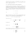
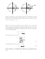
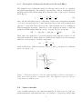
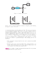
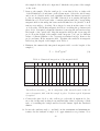
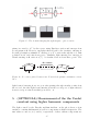
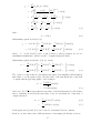
Q 3. Write down the normalized Jones column vector for horizontally, vertically, left and right circularly polarized light?
Suppose that the Jones vector for polarized incident beam Ẽi is represented by
Ẽt after transmission through an optical element then, the optical element can be
represented as a 2 × 2 transformation matrix J, called the Jones matrix, given by
Ẽt = J Ẽi
(22)
where
µ
J =
¶
j11 j12
.
j21 j22
Equation 22 can be written as,
¶µ ¶
µ ¶ µ
j11 j12
Ẽix
Ẽtx
=
.
j21 j22
Ẽty
Ẽiy
(23)
(24)
If the beam passes through a series of optical elements represented by the matrices
J1 , J2 , J3 , ..., Jn , then
Ẽt = Jn , ..., J3 , J2 , J1 Ẽi .
(25)
The matrices do not commute, so they must be applied in proper order.
Q 4. Show that the transformation matrix Jh for horizontal linear polarizer is
µ
Jh =
¶
1 0
.
0 0
(26)
(HINT: Write expression (25) for maximum and zero transmittance, solve the
simultaneous equations to get the coefficients of transformation matrix.)
3
3.1
Experimental Technique
Why PSD in Faraday rotation?
You have already performed an introductory experiment of using the lock-in amplifier, so without discussing the details of the technique and the instrumentation
any further, we will only focus on why are we using phase sensitive detection (PSD)
in this experiment. Consider a simple optical system used to measure the transmission of light through a medium. Let us suppose a small response obscured by
overwhelming noise is to be measured. The output signal in this case will be,
Vo = Vsig + Vnoise .
(27)
The noise and signal amplitudes for such a system as a function of frequency
are shown in Figure (7) [4]. The large peaks at 50 Hz and its multiples are due
10