1
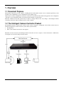
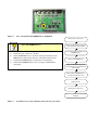
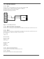
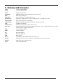
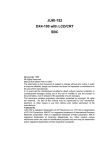
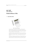
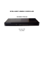
INTELLIGENT CAMERA CONTROLLER
Installation Manual
Revision 2.02
June 2004
Table of Contents
1.
OVERVIEW ......................................................................................................................................................................... 3
1.1
1.2
1.3
2.
INTELLIGENT CAMERA CONTROLLER INSTALLATION .................................................................................... 5
2.1
2.2
2.3
3.
DOCUMENT PURPOSE ...................................................................................................................................................... 3
THE INTELLIGENT CAMERA CONTROLLER PRODUCT ...................................................................................................... 3
ASSOCIATED DOCUMENTS .............................................................................................................................................. 4
FRONT PANEL INDICATORS .............................................................................................................................................. 5
ELECTRONIC CIRCUIT ..................................................................................................................................................... 5
EMBEDDED FIRMWARE ................................................................................................................................................... 5
CONNECTING DEVICES.................................................................................................................................................. 7
3.1
PORT ELECTRICAL PROTOCOLS & PIN ASSIGNMENTS ..................................................................................................... 7
3.2
PC OR LAPTOP ................................................................................................................................................................ 7
3.2.1
Cable and Connection ............................................................................................................................................ 7
3.2.2
Testing the Connection Between the ICC and a PC ............................................................................................... 8
3.3
CAMERAS ........................................................................................................................................................................ 8
3.3.1
Pelco SpectraDome ................................................................................................................................................ 9
3.3.2
Hitron Fastrax II .................................................................................................................................................. 10
3.3.3
Testing the Connection Between the ICC Controller and a Camera.................................................................... 11
3.4
FUEL DISPENSERS ......................................................................................................................................................... 12
3.4.1
Protocol................................................................................................................................................................ 12
3.4.2
Cable and Connection .......................................................................................................................................... 12
3.4.3
Testing the Connection Between the ICC and a Dispenser .................................................................................. 14
3.5
DVR TEXT IN ............................................................................................................................................................... 14
3.5.1
Protocol................................................................................................................................................................ 14
3.5.2
Cable and Connection .......................................................................................................................................... 15
3.5.3
Testing the Connection Between the ICC and a Text Inserter.............................................................................. 16
3.6
POINT OF SALE .............................................................................................................................................................. 16
3.6.1
Protocol................................................................................................................................................................ 16
3.6.2
Cable and Connection .......................................................................................................................................... 16
4.
TYPICAL CONFIGURATION ICC & DVR .................................................................................................................. 17
5.
GLOSSARY AND ACRONYMS...................................................................................................................................... 18
Filename= ICC Installation Manual 2.02
ICC Installation Manual v2.02
2
31/05/2004
1. Overview
1.1 Document Purpose
This manual is intended to provide a guide to installing the ICC. This manual assumes a level of technical proficiency of the
installer in data communication, video communication and computer usage.
Only the most common configurations and device connections are described in this manual. The application and configuration
of the ICC is open and flexible and may be customised by the installer to specific needs.
Both this document and the ICC product may be subject to change without notice. Any change to the Intelligent Camera
Controller product may require an updated revision of this document.
1.2 The Intelligent Camera Controller Product
The Intelligent Camera Controller (ICC) camera control system is designed to intelligently control CCTV cameras based on
information supplied by external electronic systems. These systems include:
•
Fuel dispensers
•
Point of sale terminals and electronic cash registers.
Particular event data received by the Intelligent Camera Controller can also be output to a Video Text Inserter or DVR device
for integration onto the video images from the camera.
ICC Installation Manual v2.02
3
31/05/2004
1.3 Associated Documents
The configuration of the Intelligent Camera Controller system is done via the Intelligent Camera Controller Manager, a
Windows software application that runs on a PC connected to the Intelligent Camera Controller. This Intelligent Camera
Controller Installation Manual is to be used alongside the User Manual.
The Intelligent Camera Controller supports connections to several external devices; this document provides the necessary
configuration information to communicate with these external devices.
These include:
•
Video Text Inserters & Digital Video Recorders
•
Cameras
•
Fuel dispensers & dispenser controllers
• POS terminals
For more detailed information refer to the manuals and documentation provided by the suppliers of these devices.
ICC Installation Manual v2.02
4
31/05/2004
2. Intelligent Camera Controller Installation
The ICC consists of hardware and embedded firmware used to control external devices connected to the ICC hardware.
Figure 1.
Intelligent Camera Controller.
2.1 Front panel indicators
The ICC has a series of LED indicator of the front panel to allow immediate visual indication of the ICC’s activity.
The Power/Run LED’s should normal be flashing once a second indicating the ICC has power and is running normally.
Each port has a pair of LED’s associated with data being transmitted (TX) or received (RX) labelled 0 to 7. Activity on these
LED’s is dependent on the type of device connected to that port.
2.2 Electronic Circuit
The ICC processor board has the following specification:
•
80C51U2 microprocessor.
•
32k bytes Battery backed Non-volatile RAM.
•
64k bytes EPROM.
•
8 Serial ports.
•
Watchdog circuitry.
•
8 TTL parallel inputs and outputs.
•
3x optically isolated current loop inputs.
•
Indicator LED'
s.
2.3 Embedded Firmware
The embedded firmware (software) in the ICC is supplied in a Flash PROM. When an ICC product is purchased the correct
version of software has been preinstalled.
However in the event where the embedded firmware is upgraded the EPROM device will require replacing and/or
reprogramming.
Embedded software versions are distributed in INTEL HEX file format, which must be programmed into an EPROM using an
EPROM programmer.
The diagrams below show the internal printed circuit board with the EPROM device highlighted. In the situation where the
EPROM device is to be exchanged then the device that is highlighted will be replaced.
ICC Installation Manual v2.02
5
31/05/2004
Figure 2.
ICC - internal PCB with EPROM device highlighted
Switch power to the ICC off.
Why doesn’t the Power/Run LED flash after I have
replaced the EPROM device?
If the Power/Run LED is not flashing then there is a problem with the ICC.
1) Check the power connection to the ICC.
2) Check the EPROM device is oriented correctly (the dot/notch on the
EPROM device matches the white dot on the printed circuit board).
3) Check that the EPROM device contains the correct firmware.
4) Check that the EPROM device is the correct type (AT29C010A or
equivalent).
Remove the lid of the ICC enclosure
exposing the printed circuit board.
Locate and note the orientation of the
EPROM device.
Remove the EPROM device.
Replace EPROM with new version
ensuring that the correct firmware has
been loaded.
Ensure that the EPROM device is
correctly oriented in the socket
Replace the lid.
Switch power to the ICC on.
Check to see that the Power/Run LED
is flashing.
Figure 3.
To install a new version of firmware follow the above procedure.
3. Connecting Devices
This section details how to connect the ICC to external devices. It also specifies how to test each connection and where
appropriate how to configure a device to work with the ICC.
3.1 Port Electrical Protocols & Pin Assignments
The 8 serial ports on the ICC support various electrical protocols described below.
Port Number
0
RS232
Yes
1
Yes
2
Yes
3
Yes
Yes
Pump Loop 1
4
Yes
Yes
Pump Loop 2
5
Yes
Yes
POS/Till 1
6
Yes
Yes
POS/Till 2
7
Yes
Yes
Camera(s)
Pin Number
1
3.2
RS485
SNIFF
TYPICAL CONNECTION
PC – ICC Manager
Spare
Text Out to VCR or DVR
All Ports
RS485 Ports 1-6-7
SNIFF Ports 3-4-5
6
Tx +
PEC (Task)
7
Tx -
PEC (Standard)
8
Rx +
Gilbarco
9
Rx -
Common
2
RS232 Receive Data
3
4
RS232 Transmit Data
5
Ground
PC or Laptop
This section describes how to connect the ICC to a PC or laptop. A PC is needed to run the ICC Manager software to configure
the ICC.
A configuration download is used to send setup parameters from a PC or Laptop to the ICC, this enables the ICC to run in a
stand-alone mode. Once the ICC has been configured with the user parameters the ICC no longer requires a physical
connection to a PC. The PC can also be used to receive diagnostics and information from the ICC.
The connection from the PC to the ICC is by RS232 serial cable to the port labelled ‘0’.
3.2.1 Cable and Connection
This cable is supplied with the ICC.
If a longer cable is needed a 0.2mm 4 core screened data cable should be used.
The connection cable pin-out is show below in Figure 4.
ICC Installation Manual v2.02
7
31/05/2004
6
7
8
9
1
1
Rx
Tx
2
3
Rx
Tx
4
2
3
4
Gnd
5
ICC
Figure 4.
5
6
7
8
9
PC
ICC to PC Connection
3.2.2 Testing the Connection Between the ICC and a PC
1)
2)
3)
Connect the ICC port 0 to one of the available Com ports on the PC.
Run the ICC Manager.
ICC “Online” status and version number is displayed when connected.
The ICC Manager shows “ICC Offline”.
What does this mean?
If the About Window displays this text then there is problem with the
communications from the PC to the ICC.
1) Check that the ICC is powered on and the ‘Run/Power’ LED on the front
panel is flashing.
2) Check that ICC Manager is configured to use the correct PC COM Port.
3) Check that the ICC to PC cable is plugged into the correct Com port.
4) Check that the cable wiring is correct – refer Figure 4.
3.3 Cameras
This section describes how to connect the ICC to a camera. The ICC supports the ability to control many types of approved
cameras.
The ICC Manager provides the ability to move the camera manually using control buttons in the “presets” tab. This is used to
position the camera to desired locations so that presets can be configured and stored. The manual controls also allow the
camera to be moved independently of any presets stored in the ICC. Camera presets are stored in the camera itself.
Most Dome & PTZ cameras use a 2-wire RS485 connection to communicate to and control the camera. The Camera should
therefore use either port 6 or 7. Up to 3 cameras can be connected to each port of the ICC.
Warning: The ICC Manager is unable to control the camera to set-up camera presets until the camera device driver
settings have been sent to the ICC. Using ICC Manager, after selecting the Camera, Port and Protocol type then
select Send Data to ICC.
ICC Installation Manual v2.02
8
31/05/2004
3.3.1 Pelco SpectraDome
3.3.1.1 Cable and Connection
The ICC uses D9 type male connectors to connect to cameras.
Typically Cat5 UTP cable is used.
1
2
3
4
5
6
7
8
9
Tx+
TxRx+
Rx-
Rx+
RxTx+
Tx-
ICC
Figure 5.
Camera
ICC to Pelco Camera Connection
3.3.1.2 Spectra II settings
The following switches set the communications speed and addressing for camera 1.
Switch 1
1
2
3
4
5
6
7
8
Position
ON
OFF
OFF
OFF
OFF
OFF
OFF
OFF
Switch 2
1
2
3
4
5
6
7
8
Position
ON
OFF
OFF
OFF
OFF
ON
OFF
OFF
3.3.1.3 Spectra III settings
The following switches set the communications speed and addressing for camera 1, 4800 Baud.
Switch 1
1
2
3
4
5
6
7
8
Position
ON
OFF
OFF
OFF
OFF
OFF
OFF
OFF
Switch 3
1
2
3
4
5
6
7
8
Position
OFF
OFF
OFF
OFF
OFF
ON
OFF
OFF
Switch 2 must be on when there is one camera fitted or on for the last camera in the circuit if more than one fitted.
Full set-up of the Spectra III is available using the ICC Manager “Presets” Camera Control TAB by selecting preset 95 and Set
Preset. Refer to the camera manual for a full description of configurable functions.
Optionally the Spectra III “Freeze Frame” may be turned on, this freezes the last frame when moving to the next preset with no
blurred image while moving. Select preset 95, Set Preset, use the up & down functions and Iris Open to navigate. Go through
the camera menus Camera-Motion-Freeze Frame and change to ON.
ICC Installation Manual v2.02
9
31/05/2004
3.3.2 Hitron Fastrax II
3.3.2.1 Cable and Connection
The ICC uses D9 type male connectors to connect to cameras.
Typically Cat5 UTP cable is used.
A RS485 connection is used Pin 8 & 9 do not need to be connected.
1
2
3
4
5
6
7
8
9
Tx+
TxRx+
Rx-
Rx+
RxTx+
Tx-
ICC
Figure 6.
Camera
ICC to Fastrax II Camera Connection
3.3.2.2 Hitron Fastrax II settings
The following switches set the communications speed and addressing for camera 1.
Switch 4
Position
1
Switch 2
1
2
3
4
5
6
7
8
Position
ON
ON
ON
OFF
OFF
OFF
OFF
OFF
ICC Installation Manual v2.02
10
31/05/2004
3.3.3 Testing the Connection Between the ICC Controller and a Camera
1)
2)
Enter the Camera Control window of the ICC Manager and using the arrow/direction buttons determine if the camera
is responding to the correct direction movement.
Adjust the Camera Speed setting and determine if this affects the speed at which the camera moves corresponding to
the arrow/direction buttons.
Why doesn’t the camera respond to the arrow/direction
buttons?
If the camera is not responding to the arrow/direction buttons then there is
likely to be a communications error.
1) Check the camera has been setup using the ICC Setup menu on the ICC
Manager.
2) Check that the Camera device is setup correctly and the configuration has
been sent to the ICC
3) Check that the ICC is powered on and the ‘Run/Power’ LED on the front
panel is flashing.
4) Check that the ‘Camera’ Tx LED on the front panel flashes when
arrow/direction buttons are pressed.
5) Check the ICC to Camera cable is plugged into the correct port.
6) Check that the cable wiring is correct – refer section 3.3.
7) Check that the configuration switches are correct on the camera.
ICC Installation Manual v2.02
11
31/05/2004
3.4 Fuel Dispensers
This section describes how to connect the ICC to dispenser communication circuits. Connections to the dispenser
communication circuits enable the ICC to listen to the dispenser data being transmitted from dispensers to the dispenser
controller. Typically the ICC connects to the dispenser controller as if it is another dispenser. The ICC can connect to a
maximum of 32 dispensers across 3 circuits.
3.4.1 Protocol
The ICC supports connections to dispenser communication loops using the electrical protocol supported by the specific
dispenser type. Typically a small site will have one dispenser loop or circuit with up to 16 dispensers on that circuit. A large
site may have up to three circuits.
The most common electrical protocols used are:
•
20 or 40mACurrent Loop (ICC Ports 3, 4 & 5)
•
RS485 (ICC Ports 1, 6 & 7)
Warning: Connections to the dispenser communications must normally be done live, Beware not to short or open
the circuit and cause any disruption to the service station operation and ability to sell fuel.
3.4.2 Cable and Connection
The ICC uses D9 type female connectors to connect to dispenser communication loops.
Typically either Cat5 UTP or 0.2mm screened data cable is used.
The receive LED for the port connected will flash when correctly connected.
3.4.2.1 Gilbarco Australia 45mA
Gilbarco dispensers use a current loop circuit; therefore electrically the ICC connects in series with the existing dispensers.
The dispenser communications cables terminate to the Gilbarco “Blue Box”.
Connect the ICC circuit to the blue box as if it were a dispenser along with a 68Ω shunt resistor. An “ICC” label should be
fitted under the switch, which should not be turned off.
Figure 7.
Blue Box
Figure 8.
Blue Box Open
ICC Installation Manual v2.02
12
31/05/2004
Figure 9.
1
2
3
4
5
Shunt Resistor
6
7
8
68ohm
9
ICC
Figure 10.
Bluebox
Connectors
ICC Gilbarco connection
3.4.2.2 Tokheim
Tokheim dispensers must use a RS485 Port.
3.4.2.3 Dresser Wayne
Dresser Wayne dispensers use a current loop similar to Gilbarco.
ICC Installation Manual v2.02
13
31/05/2004
3.4.3 Testing the Connection Between the ICC and a Dispenser
In order to test the ICC the dispenser loops and camera preset information has to be setup using the ICC Manager.
1)
Wait for a nozzle to be lifted on one of the dispensers, and then check the Text Inserter to verify that the nozzle lift
event has been registered and corresponds to the correct dispenser.
Why doesn’t the ICC respond to dispenser events?
If the ICC is not responding to dispenser events then there is likely to be error
with the dispenser loop, camera or the text inserter communications.
1) Check the corresponding Rx for the connected port is flashing.
2) Check that the ICC is powered on and the ‘Run/Power’ LED on the front
panel is flashing.
3) Check the dispenser loops and types have been setup correctly using the
ICC Manager.
4) Check that cables are connected to the correct ports (refer sections
above).
5) Check that the dispenser communications cable wiring is correct.
3.5 DVR Text In
This section describes how to connect the ICC to a Text Inserter. Connections to the text inserter enable the ICC to send data to
a Text Inserter which then overlays the text onto a video image. Therefore the ICC is able to associate dispenser & POS
information with a particular image.
The Text Inserter is connected to the ICC on port 2 using an RS232 connection.
Most DVR’s support video motion detection (VMD), it is recommended VMD is turned off for controllable cameras and on for
fixed cameras. Refer to the DVR manual for advanced configuration and function settings.
3.5.1 Protocol
The ICC uses a DB9 type male connector to connect to a Text Inserter. The ICC uses a RS232 connection to send text
messages to the text inserter or DVR for display with an image.
All data is captured and transmitted from the ICC in real-time.
3.5.1.1 Dispenser Transactions/Events.
Pump xx
(this indicates an idle roam event)
Pump xx Nozzle lifted
Pump xx Dispensing
Pump xx Nozzle replaced
Pump xx Hose xx Finished
$xxx.xx xxx.xx
3.5.1.2 Point of Sale (POS) Transactions/Events
The ICC does not interpret any POS data; the ICC consolidates the data from multiple sources and formats it for recording with
the image and being searchable.
ICC Installation Manual v2.02
14
31/05/2004
3.5.2 Cable and Connection
3.5.2.1 Kalatel
The ICC connects to the Text In RS232 port 2 using a Cat 5 UTP cable RJ45 to D9M.
The DVR port must be configured in the DVR setup menu to 19200,8,N,1.
Pressing the camera button twice enables text OSD.
The default set-up menu password is 3477.
6
7
8
9
1
2
3
Rx
Tx
4
5
Gnd
1
4
RJ45
5
1
2
3
4
5
6
7
8
Kalatel
ICC
Figure 11.
ICC to Kalatel Connection
3.5.2.2 PDR 16 Rack Windows XP Embedded
The ICC connects to the Text-in port on this DVR. This model DVR uses the same cable as described in section 3.2.1
3.5.2.3 SDR 40
The ICC connects to the Text-in port on this DVR. This model DVR uses the same cable as described in section 3.2.1
The following must be configured for the DVR to accept text from ICC.
Port => TextIn
On/Off => On
Keyword1 => POS
Keyword2 => Pump
Delimiter => ^J^J
Line Count => 1
Baud Rate => 9600
Data Bit => 8
Stop Bit => 1
Parity => None
3.5.2.4 Vision System Adpro Fastrace
This model DVR uses the same cable as described in section 3.2.1
3.5.2.5 Cashcam
This connection is described in the Cashcam Installation Manual.
ICC Installation Manual v2.02
15
31/05/2004
3.5.3 Testing the Connection Between the ICC and a Text Inserter
In order to test the ICC and the Text Inserter as a minimum the dispenser loops have to be setup using the ICC Manager and a
preset assign to the Idle Event. (A camera is not required for this test).
Why doesn’t the Text Inserter display any text messages
from the ICC?
If no text messages are displayed on the Text Inserter then there is likely to be
an error with events being generated or the text inserter communications.
1) Check the Text Out Tx LED is flashing when an event occurs to ensure
that information is being passed to the Text Inserter.
2) Check that the ICC is powered on and the ‘Run/Power’ LED on the front
panel is flashing.
3) Check that cables are connected to the correct Com ports (refer sections
above).
4) Check the text inserter or DVR is configured correctly.
3.6 Point of Sale
3.6.1 Protocol
The communications between the ICC and the POS uses the serial RS232 protocol.
3.6.2 Cable and Connection
3.6.2.1 Generic Customer Display
Where the POS does not have a specific video text output it may be connected by tapping into the data sent to the customer
display. Figure 12 show a connector cable assembly to tap into this RS232 data.
The ICC default setting for the customer display input is 9600,8,N,1.
1
2
3
4
5
6
7
8
9
1
2
3
4
5
6
7
8
9
POS
1
2
3
4
5
6
7
8
9
1
2
3
4
5
6
7
8
9
Customer
Display
1
2
3
4
5
6
7
8
9
ICC
Figure 12.
ICC Customer Display Connection
ICC Installation Manual v2.02
16
31/05/2004
4. Typical Configuration ICC & DVR
Figure 13 shows a typical fuel station configuration with one Dome Camera, one POS and one Dispenser loop.
POS
Camera
Control
Pump
Transaction
Data
POS
Transaction
Data
Port 7
Port 5
Port 3
Port 1
Intelligent Camera Controller
Port 6
Port 4
Port 2
PC (ICC Manager)
DVR
Figure 13.
Port 0
ICC DVR System
ICC Installation Manual v2.02
17
31/05/2004
5. Glossary and Acronyms
ATM:
CCTV:
DVR:
Dwell Time:
ECR:
Embedded:
Event priority:
ICC Controller:
ICC Manager:
GUI:
Initial Priority:
Inter-visit:
LPR:
OSD:
PC:
PCB:
POS:
Preset:
Priority:
TLVCR:
VCR:
Automatic Teller Machine.
Closed Circuit Television.
Digital Video Recorder.
The length of time a camera will remain at a preset location.
Electronic Cash Register.
Software that runs on a dedicated processor.
The priority or importance of an event, a number from 1 to 5 (1 highest, 5 lowest).
The box that any devices are attached to.
The PC based GUI program that communicates with ICC Controller.
Graphical User Interface.
The first priority that the event has when it occurs.
The time that must expire before the camera will return to look at a position. In effect it is a period
when the camera will ignore that position.
License Plate Recognition.
On Screen Display.
Personal Computer.
Printed Circuit Board.
Point Of Sale.
A predefined position that the camera can be moved to.
The importance of an event or a reference to the time that a camera views a preset.
Time Lapse Video Cassette Recorder.
Video Cassette Recorder.
ICC Installation Manual v2.02
18
31/05/2004