1
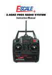
Telecommunications
Telecommunications
Telecommunications Workstation
Antenna Lab
Transmission Lines
Microwave Prinicples
Microstrip Technology
Fibre Optics
Wireless Communications
LAN Trainer
Network & Data Security
AM & FM Radio
Espial Courseware
Telecommunications is one of the world’s fastest
growing industries and world-wide personal
communication of voice, picture and data is now
commonplace.
The Feedback range of Telecommunications
training equipment has been designed to provide
a modern, efficient approach to training the
engineers and technicians working in this field.
Feedback’s philosophy is to equip students
with the fundamental ideas and principles that
underpin modern telecommunications practice by
using versatile trainers that quickly and clearly
demonstrate the required characteristics.
Paramount to all Feedback equipment is the principle
that students of engineering and technology
should work with hardware and be allowed to take
a hands-on approach. All of Feedback’s teaching
hardware is supported by extensive teaching and
theoretical courseware. This can either be in the
form of paper manuals or software.
Within the Telecommunications range, Feedback
offers hardware that can be used in conjunction
with conventional test and measurement equipment,
using paper manuals. Alternatively, laboratory work
can be carried out using equipment connected to
a PC enabling it to take advantage of Feedback’s
Espial courseware, which offers on-screen instruction
and embedded, real-time, virtual instrumentation.
Both these teaching philosophies are valid ways
of demonstrating technical characteristics, but the
underlying principle that both share is giving the
student the opportunity to work with real hardware
and avoid simulation.
Features
• Ideally suited for University and Technical College courses
• Covers analogue and digital telecommunications
• All products provided with in-depth teaching manuals
or software
• Compact, bench-top systems
• Teaching material relevant to industrial practice
Telecommunications
- 32 -
mmunications Workstation 53-004
nician
aching
nts
lation
e
nd
ESPIAL
The Telecommunications Workstation range of products consist of a
series of open-board trainers that work in conjunction with Discovery software.
S oft wa re
The 53-004 comprises three workboards: Amplifiers and Oscillators 53-210,
Tuned Circuits and Filters 53-220 and Modulation and Coding 53-230 and
the 92-200 USB Real-time Access Terminal (RAT).
The close integration of the hardware workboard with computer-based
instruction and instrumentation software provides the student with a rich
learning environment and the tutor with a cost-effective solution in this
field of telecommunications teaching.
d, theory
ons
bedded
ding a
ents of
operties
yzer
red
on or
th
Integrated instructions
and Instrumentation
Integrated instructions and instrumentation
Further in-depth information
always available
Further in-depth information always available
Each practical experiment is configured by patching together circuit blocks on
the boards. The patching sequence is shown sequentially through the software.
The workboard connects to a personal computer via the USB Real-time
Espial
Software is Feedback’s Espial is written in such a way that its
The interactivity of
Access Terminal (92-200 RAT), which is a fast Analogue-to-Digital converter,
continuously evolving software package. appearance and the instrumentation
Espial means that it
sampling signals on the workboard at rates from 10 to 100MHz, as required.
The basic and most important made available depends on the
provides real-time, PC
The Terminal also provides all the necessary power supplies for the workboard.
philosophy of Espial is its interactivity practical being executed. So, if the
based instrumentation
with teaching hardware. Espial can practical requires the display of a
and in the case of
be applied to products within our constellation or a phase meter, as
Telecommunications this
complete range of teaching products in QAM experiments, one is made
includes:
and is used extensively within the available whereas at lower levels
Telecommunications range.
of study it would not be provided.
• Dual channel
Espial software can be installed either
Oscilloscope
The learning material is provided in a stand-alone configuration or
• Spectrum Analyzer
within the software and this includes networked and centrally served.
• Voltmeter
the underlying theory, which is written
• Frequency Counter
in such a way that it does not use
• Phasor and
mathematics at too high a level.
Constellation Displays
An important part of the teaching
• Bit Error Rate (BER)
programme is to highlight the learning
Meter
objectives of the various experiments
• Antenna Polar
and convey the background involved
Diagram Plotter
to the student: This information is also
included in the software. Consequently,
the student is suitably prepared to start
the practical work using the hardware.
ers and Oscillators Workboard 53-210
ge
r
ier
buffering
r
This workboard allows the construction of various Amplifiers, Oscillators and
Signal Sources. The workboard shows the principles of R-C, L-C and crystal
oscillators, feedback, loop gain, amplitude stabilisation, oscillation, distortion
and frequency stability. Using the PC instrumentation, Nyquist and Bode
diagrams can be easily shown.
Telecommunications
- 33 -
57-200
AntennaLab
Features
• Feedback Espial
teaching software
• Unique integration of
hardware and software
• Models and tests
real antennas
• Hardware modelling
‘between 1200 MHz
and 1800 MHz
• PC based measurement
and results
• Rapid, graphic
display of antenna
characteristics
• Bench-top operation
• Low, safe power output
• USB interface
The AntennaLab is a unique system
designed to be used in two distinct
ways: for teaching and demonstrating
common antenna configurations at all
levels of study, and as a design tool
by those engaged in research and
development.
The equipment comprises two towers,
one being a low power transmitter,
controlled by a frequency synthesizer.
The second contains a frequency
synthesiser controlled receiver. The
antenna to be investigated is mounted
on top of the transmitter tower.
The transmitter tower can be rotated
through 360 degrees and displays
the following characteristics:
• Signal level
• Frequency response
• Polar diagrams
• Return loss plots
• E & H planes in three dimensions
• Bandwidth
Telecommunications
- 34 -
Subject Areas
•
•
•
•
•
•
•
•
•
•
•
•
•
•
•
The Dipole in free space
Effects of the surroundings
Dual sources
Gain, directivity and aperture
Ground reflections
The monopole
Phased monopoles
Resonance, impedance and
standing waves
Return loss and VSWR measurements
Parasitic elements
Multi-element parasitic arrays
Stacked and bayed arrays
The log periodic antenna
The horn antenna
The dish antenna
TLD511
Transmission Line Demonstrator
TLD511 Transmission Line Demonstrator
TLD511 Transmission Line Demonstrator
This system demonstrates the characteristics
of transmission lines in a graphic manner.
The system uses a simulated line that
effectively displays the high frequency
characteristics of a transmission line at
low frequencies so that they can be easily
observed. The line characteristics can be
easily adjusted by the operator. The line is
completely symmetrical so that either end
may be regarded as an input or an output.
The unit features large, bright LEDs, a builtin step function generator and is supplied
with a manual.
Subject Areas
Features
•
•
•
•
•
•
•
•
•
•
•
•
•
•
•
•
•
Propagation of a wave front
Propagation of a sinewave
Effect of wavelength
Attenuation and dispersion
Terminations
Reflection, standing waves and
characteristic impedance
Partial reflection, standing waves and
superposition of incident and reflected waves
Resonance and the effect of attenuation
1 to 1 impedance transformations
Lines with dissimilar lossless terminations
Resonance and capacitive detuning
Reactive line impedance either side of resonance
Large bright LED display
Built-in step function process
Variable simulated line length
Manual hold facility
Comprehensive manual
Variable Phase Generator
VPG608
Recommended accessory:
•
•
•
•
•
Frequency range 0.01 Hz to 1 kHz
Phase shift from -180° to +180°
Outputs variable up to 10 V pk - pk
Attenuation of x 1 x 0.1 and x 0.01
Square & triangular auxiliary
outputs
• VCF and SYNC facility
ASD512 - Antenna System Demonstrator
ASD512 Antenna Demonstrator
This is a fully operational antenna system
that has been designed to provide an
ideal classroom demonstrator.
The system uses a kit of parts to allow
many types of antenna to be constructed,
making the system versatile as a
demonstrator of both antenna principles
and practice.
Two hand-held detectors are provided
that show relative magnitudes of voltage
and current fields around the antenna,
and the field strength of the antenna. The
system works at a frequency of 167.2
MHz, giving a half-wave element of
approximately 90 cm.
Features
Subject Areas
•
•
•
•
•
•
•
•
•
•
•
•
Basic theory of radiation
Radiating and non-radiating systems
Feeders
Radiation resistance
Drive point impedance and ground resistance
Physical and electrical length
Directional antennas and radiation patterns
Parasitic arrays & antenna gain
Antenna with folded elements
Slot radiators
3-dimensional polar diagrams
Loop antenna
• Fully operational antennas
• Displays of antenna
characteristics
• Convenient size for
classroom
• Versatile and easy to
assemble
• Complex concepts made
easy
• Reconciles theory and
practice
Telecommunications
- 35 -
AM2961/FM2962
Radio Systems Trainer
AM2961 Radio Systems Trainer
FM2962 FM Stereo Radio Systems Trainer
Features AM2961
• Covers the principles of AM
radio signal generation and
reception
• Single and Double sideband
with suppressed carrier
• Receiver operating at 500
- 1600 kHz (MW) & 3 - 4
MHz (SW)
• One fixed generator
frequency in each band
• Switched faults on both
boards
Features FM2962
• Covers the principles of FM
radio signal generation and
reception
• Stereo transmission and
reception
• Extensive use of monitoring
points for signal tracing
• Switched faults on both
boards
AM Radio Systems Trainer AM2961
The AM Radio Systems Trainer comprises
two open-boards: AM2961A, AM/DSB/
SSB generator AM2961B, AM/DSB/SSB
receiver. The AM circuits operate within
the AM broadcast band and the DSB/
SSB circuits operate within the 80 m ‘ham
band’. The generator output is only a few
milliwatts, so the range of transmission is
extremely limited.
The receiver has an integral antenna, but
may also be used, with the addition of
an external antenna, to receive normal
broadcast and amateur signals. The
principles and techniques of AM with
full carrier, double-sideband and singlesideband suppressed carrier transmission
and reception can be easily investigated.
Subject Areas - AM2961
•
•
•
•
•
•
•
Modulation and demodulation
Mixing techniques
Filtering
RF and audio AGC
RF, IF and AF amplification
LC, crystal and VCO oscillators
Single and double sideband
Telecommunications
- 36 -
FM Stereo Radio Systems Trainer
FM2962 - The FM Stereo Radio Systems
Trainer comprises two open-boards:
FM2962A, stereo generator & FM2962B,
stereo receiver. The FM receiver circuits
operate over a range of 88-108 MHz
and the generator provides a fixed output
frequency of 100 MHz with a 19 kHz pilot
tone. The generator output is only a few
miliwatts, so the range of transmission is
extremely limited.
The receiver operates on an IF frequency
of 10.7 MHz in stereo or mono mode
and may also be used with an external
antenna to receive normal broadcast and
amateur signals. Switched faults can be
introduced on both generator and receiver
units. Fault options include Multiplex, Pilot
tone and Mute errors; power for tuner,
audio and demodulator, forces tuning volts
to zero and high-gain AFC loops locking
to a signal.
Subject Areas - FM2962
• Familiarisation with FM multiplex stereo
transmission and reception
• Frequency modulation
• Stereo multiplex encoding, pre-emphasis,
pilot tones and sub-carriers
• FM reception, filtering, limiting and AFC
• FM demodulation
• Stereo multiplex decoding, de-emphasis
and audio amplification
53-004
Telecoms Workstation
53-004 Telecommunications
Workstation.
The system comprises: Amplifiers and
Oscillators 53-210, Tuned Circuits and
Filters 53-220 and Modulation and
Coding 53-230 and PC interface.
Teaching content and instrumentation is
provided using Espial software.
53-210 Amplifiers & Oscillators Workboard
53-210 Amplifiers and Oscillators
Workboard. This workboard allows
the construction of various Amplifiers,
Oscillators and Signal Sources. The
workboard shows the principles of R-C,
L-C and crystal oscillators, feedback,
loop gain, amplitude stabilisation,
oscillation, distortion and frequency
stability. Using the PC instrumentation,
Nyquist and Bode diagrams can be
easily shown.
53-220 Tuned Circuit and
Filters Workboard. With these
circuits, students can examine the
principles of passive filters, R-C and L-C
tuned circuits, Q loading, low-pass crystal
filters, active filters, tuned amplifiers and
automatic gain control (AGC).
53-220 Tuned Circuits & Filters Workboard
53-230 Modulation and Coding
Workboard. Is a fully-featured,
complete, laboratory course covering
the principles of operation and the
practical implementation of modern
modulation systems required for both
analogue and digital communication
systems.
Subject Areas- 53-210
• Voltage, Current input and
Controlled gain amplifier
• Oscillation criteria
• Wien bridge oscillator
• Tuned amplifier
• LC & Crystal oscillator
• Oscillator stability & buffering
• Multivibrator
• Tuned power amplifiers
Subject Areas - 53-220
• Crystal filters
• Tuned & coupled tuned circuits
• Ceramic bandpass & LC high
pass filters
• Audio op-amp & LC low pass filters
• Butterworth, Chebyshev &
High-order filters
Subject Areas- 53-230
• Signals in the time and
frequency domains
• Sampling and Time Division
Multiplexing (TDM)
• Amplitude Modulation (AM)
& AM with Suppressed Carrier
• SSB generation with an
IQ modulator
• Amplitude Shift Keying (ASK)
• Frequency Modulation (FM)
& FM with an IQ modulator
• Frequency Shift Keying (FSK)
• Phase Modulation (PM)
• Phase Shift Keying (PSK)
• Multi-state Phase Shift Keying
• Quadrature Amplitude
Modulation (QAM)
• Uncoded binary data formats
• Bi-phase data format
• Alternate mark inversion
53-230 Modulation & Coding Workboard
Telecommunications
- 37 -
56-200
M i crowa v e Tr a in e r
56-200 Microwave Trainer
Features - 56-200
• Stand-alone, low cost
system
• No ancillary equipment
required
• Simple, robust stands for
antennas
• Modulated 10.425 GHz
solid-state DRO source
• Components identified
with inscribed reference
number
Microwave Trainer 56-200 - This
instrument allows the user to investigate
the principles of microwave transmission
systems, such as those used in radar and
communications. It uses standard type
WG16 (WR90) wave-guide components
to illustrate the essential elements. It is
completely self-contained and allows
students to carry-out realistic practical
work.
The equipment has a modulated dielectric
resonance oscil ator (DRO), X-band source,
a selection of waveguide components, a
console containing a power supply, a
demodulation circuit and a meter that
monitors the detector output.
Subject Areas - 56-200
• Introduction to microwave waveguide
bench and measurement of source
frequency and guide wavelength.
• Voltage Standing Wave Ratio (VSWR)
• Diode detector law
• Impedance and impedance matching
• Measurement of radiation diagram
of a horn antenna
• Use of directional couplers in power
transmission and reflection measurement
• Series, shunt and hybrid tee
waveguide junctions
• Waveguide-to-coaxial transformers
Features - 56-901
• Impedance, dispersion
and loss calculations
• Optimisation including
eight optimisers
• Yield analysis
• Smith chart
• Planar lines analysis
and synthesis
• Integrates measured
data with simulations
• MIDE linear frequencydomain circuit simulator
56-901 MIDE Microwave Design Software
MIDE Microwave Design Software 56-901 - is a powerful engineering
program for the simulation of complex linear microwave and circuits. It is used to
determine transmission, reflections, stability and gain of circuits.
Telecommunications
- 38 -
MST532-1
M i cro s t r ip Tr a in e r
The
MST532-1
microstrip
trainer uses high precision
components to allow students to
investigate microstrip technology
principles. The Complete Microstrip
System, MST532-1, needs no
additional test equipment, as it is
supplied with a digital multimeter and
a dual d.c. power supply.
A user manual is supplied that gives
students detailed background material,
theory and structured assignments,
whilst
avoiding
unnecessary
mathematical analysis. The precision
components (18 passive and 3 active)
are packaged in bright nickel-plated
enclosures and are interconnected
using industry standard SMA couplings.
Subject Areas
• Power source and detector action
• Action of a 3-port circulator
• Insertion loss measurement on
a low-pass filter
• Measurement of return loss, reflection
coefficient and VSWR of a filter, microstrip
and commercial matched loads
• Matched investigations: reflection
coefficient of unknown resistive load
and its matching by 1/4 g transformer
and shunt stub
• Properties of a power divider
and rat-race coupler
• Effective dielectric constant/ line loss
measurement with a ring resonator
• d.c. biasing and MMIC amplifier
investigations
• PIN diode modulator investigations
• Microwave radio link and antenna
investigations
Features
• Latest Microwave
technology
• 2.4 to 3.4 GHz VCO
• 2 to 4 GHz PIN diode
modulator
• No ancillary test
equipment required
• Safe, low power output
• Components identified
with inscribed reference
number
• Supplied in protective case
See ordering guide or product
datasheet for ordering options.
Telecommunications
- 39 -
EFO SERIES
Fibre Optic Trainers
Features
• Teaches fibre optic
measuring techniques
• Demonstrates
properties of light
(visible and infra-red)
• Analogue and Digital
data transmission
• Self-contained training
package
EFO1101 Fibre Optics Trainer
- investigates various aspects of
fibre optic technology and its use in
transmitting analogue and digital data,
with reference to telecommunications.
The trainer comprises an optical
transmitter with an infra-red LED, a red
LED and variable output controls. It
has an optical receiver, which includes
a loudspeaker for analogue output,
high and low impedance analogue
outputs, variable analogue gain,
buzzer, digital output and TTL, CMOS
and RS232 voltage level digital
outputs. Two lengths of fibre optic
cable, various electrical connectors
and accessories complete the kit.
EFO1102 Fibre Optics Power
Meter is an accurate, versatile and
low-cost unit for measuring optical
power levels at terminated optical
cables. An easy-to-read pointer scale
gives readings in both dBm and
microwatts. The meter ranges between
1mW (0 dBm) down to a sensitivity of
better than 1nW (-60 dBm). The meter
Telecommunications
- 40 -
is calibrated at a wavelength of 820
nm and permits accurate measurements
between 800 nm & 850 nm. Meter
connector options include SMA &
STRATOS.
EFO1105 Fibre Optics Monitor - is
a versatile, fully portable product used
to design fibre optics and general
optics measurement applications. It
uses SMA and STRATOS connections.
Subject Areas
• Shows the properties of light and
infra-red radiation
• Transmission of high quality analogue
and digital data over optical fibres and free
space using visible and infra-red light
• Converting various light sources, such as
torch-light, and infra-red light and to audio
signals
• Construction of an alarm system based on the
presence of a light signal
• Clarifying the important differences between
analogue and digital techniques
• Measurement of the optical absorption or
reflection properties of various materials
• Testing analogue or digital optical receivers
and transmitters
OFS IV SYSTEM
Optical Fibre System
OFS IV - Optical Fibre System - The OFS
IV is designed to provide comprehensive
training to students and all levels of
scientific and technical personnel on fibre
optic devices and digital communication
systems. The laboratory spans fibre optics
and related topics, including:
• Fibre optic device characteristics
• Principles of fibre optics and digital
communications
• Fibre optic equipment
• Digital and analog fibre optic links.
The OFS IV System can be used for
demonstration, training and experimentation,
and can form the basis for student and
research projects and prototypes.
OFS IV - Optional Modules and Standalones
includes the -SMC– Single Mode Fibre
Characteristics Training System which enables
comprehensive training on Single-mode fibre
characteristics such as Normalized Frequency
(V number), Modes, cut off wavelength, Mode
field diameter and Numerical aperture of a
single mode fibre/Modes observation in two
different single mode fibres having different
cut off wavelengths/Precision XYZ positioner
for coupling the free space 650 nm Laser light
into Single-mode fibre/Specially designed
mechanical setup for Mode Field Diameter
and NA measurement.
Subject Areas
• Multimode plastic & glass fibre
characteristics
• Measurement of numerical aperture,
attenuation & bending losses, EMI
and pulse broadening effect
• Attenuation & bending loss
• Clad mode stripping study
• Laser diode module
• P-I & V-I characteristics
• Line of sight link (650 nm)
• Avalanche photodiode module
• Zero bias, reverse bias, leakage
characteristics, multiplying effect of APD
• LED module
• PIN photodiode module
• Optical Time Domain Reflectometry
(OTDR)
• Digital communication concepts
• Study of 64 Kbps transmission concepts
• Time division multiplexing
• Marker in TDM and false marker
generation
• Manchester coding
• PCM voice coding
• Fibre optic link design and analysis
– analog and digital FO digital link
• Multimode digital fibre link – sensitivity
and power budget
• Bit rate measurement and study of
a.c. coupled digital link
Features
• OFT – Optical Fibre and Digital
Communications Trainer
demonstrates integrated
voice/data communication link,
TDM and digital communication
principles.
• Demonstration & Measurement
• Individual LED, LASER, PD and
APD Modules for device
characteristics study. The
characteristics modules cover
forward, reverse & zero bias,
leakage characteristics
• Specially designed componentinsertion PCBs for link construction
– for repeated use by students
• Light Source with variable
optical power output,
continuous wave, external
modulation, internal word
and PRBS generation
• Power Meter calibrated at 650,
850 and 1300 & 1550 nm
• Optional Connectorisation and
Splicing Kits provide students
with hands-on experience in
connectorisation and splicing
of glass fibre
Telecommunications
- 41 -
OFT SYSTEM
Optical Fibre Trainer
Features
• Eleven usable 64 Kbps
channels
• User definable frame marker
(two alternating 8-bit
markers - can be set to
CCITT compatible)
• Two on-board digitized
voice channels, one 8-bit
data channel and several
user-expansion channels
• Demonstrates fully
operational integrated
voice/data fibre-optic
communication link
• RS-232C communications
module optional demonstrates computer
communications over fibre
• Time Division Multiplexing
of voice, data & user-defined
data streams
• Modular design enables
configuration with userdesigned modules
• Wide scope for experimentation
through use of external
circuitry interfaced to kit
• Ready-to-use kit comes
complete with accessories
OFT - Optical Fibre Trainer - is a
powerful, versatile and cost- effective
system teaching the principles of
digital data transmission through
to fibre-optics. The OFT Trainer
facilitates demonstration, training &
experimentation in basic and advanced
concepts including principles of
fibre-optic communications, basics of
digital baseband communications,
advanced experimentation and
development in fibre optic & digital
communications.
Subject Areas
•
•
•
•
•
•
•
Fibre optic analogue links
Digital link Losses in optical fibre
Effect of EMI interference
Numerical aperture measurement
Time Division Multiplexing
Framing in Time Division Multiplexing
Manchester Coding/Decoding
– timing recovery
• Voice coding - A-law
• Pulse broadening in Fibre Optic
Communications
Telecommunications
- 42 -
Description - Principles of fibre-optic
communications - 850 nm and 650 nm
fibre links Demonstrates established
digital communication techniques
such as Time Division Multiplexing,
Transmitter & Receiver operation,
PCM voice coding at (64 Kbps),
Manchester Coding and Decoding for
timing recovery. Channels switchable
at transmitter & receiver using
time-switching principles. Easy interface
to external circuitry - all required inputs
and outputs provided and extensively
documented. Power available to
external circuitry as well.
ETS/ EDFA
Tr a i n i n g S y s t e m
The Benchmark ETS – EDFA
Training System – addresses the
need for a training setup that shows
the building blocks of a typical EDFA
as well as the characteristics of such
blocks. All the blocks are given with
proper input and output connections
such that they can be configured in
different modes of operation, such as
co-directional and counter-directional
operations. This modular approach
also facilitates study of individual block
characteristics wherever possible.
The Erbium Doped Fibre Amplifier
(EDFA) is an optical amplifier that
amplifies optical signals sufficiently to
cover several tens of kilometers without
any need for conventional repeaters.
Moreover, as it works in the same
optical domain, it avoids the need for
several stages of signal conversion
with their associated problems.
Operating principles of EDFA
• Working of EDFA in co-directional,
counter-directional pumping
• Gain
• Power Conversion Efficiency
• Quantum Conversion Efficiency
• ASE-ASE noise, signal-ASE beat
EDFA Building Blocks
• Wavelength Selective couplers
– 980 nm/1550 nm
• Tap coupler for 980 nm – 99:1
• Optical isolators – 1550 nm
• Optical circulators
• Fibre Bragg Grating (FBG)
• Optical attenuator – 1550 nm
• Measurement of absorption coefficient
• Mode field dia mismatch in EDF
• I-P Curve
• Knee Current
• Spectrum [Optical Spectrum Analyser
(OSA) also required]
• Large and small I/P signal vs
Gain Pump laser power vs Gain
• EDF length Vs Gain
• Pump saturation, signal saturation
• 1550 nm, 34 Mbps data rate
• Setting up a digital link (using the OFT)
Subject Areas - ETSEDFA
• Understanding the
operating principles
of EDFA
• Understanding the EDFA
Building blocks
• Characteristics of EDFA
• Characteristics study of
Pump Laser 980 nm
• Characteristics study of
Signal DFB Laser 1550 nm*
• Factors contributing to
EDFA Gain – Pump Laser
power, length of Erbium
Doped Fibre*
• Setting up a Fibre
Optic link with EDFA
• Fibre ring laser
(OSA required)*
Module 001 required
* Module 001 - includes
FOSM-D600 ID Driver,
FOTX-610 LD Modulator &
FORX-500 Optical Receiver
Telecommunications
- 43 -
WiCOMM - T
Digital Communications
Features
• Typical implementation
of modern communication
systems
• Interface with MATLAB
- Gives the ability to
generate required signal
and pass it through the
transmitter and receiver
providing a real life
wireless digital
communication system
• Comprehensive manual –
describes wide range of
experiments
• Loop back options at
Base- band and at IF
Digital modulations are often
expressed in terms of I (in-phase) and Q
(quadrature) signals. All modern digital
communication systems and gadgets
have three main blocks namely:
• Data processing block
• ADC and DAC conversion block
• RF block
All the blocks process the I and Q
signals simultaneously, leading to the
use of complex algebra and analysis
in their design and implementation. This
standardized and uniform approach in
building digital communication systems
or gadgets results in lower cost of
development and manufacturing. The
focus is also turned towards adding more
features and bringing in more techniques
within the available RF spectrum.
WiCOMM-T – the ultimate Wireless
Digital
Communication
Training
Platform is the actual implementation
of modern digital communication
systems with direct interface to
MATLAB through the Hi-Speed USB
port of a PC.
Telecommunications
- 44 -
The WiCOMM-T provides maximum
flexibility in learning complete digital
communication system concepts,
which includes digital modulation
techniques, Baseband Equalization,
Filtering concepts, and the basics of
CDMA, GSM etc. MATLAB codes
of all suggested experiment topics
are available to users as reference. A
MATLAB interface to the Platform also
allows users to try out other topics on
their own.
Subject Areas
•
•
•
•
•
•
•
•
•
•
•
•
•
•
•
•
•
•
•
Baseband Digital Comms Link
Raised Cosine spectrum pulses
Timing acquisition algorithm
Matched filtering – performance in noise
Quadrature Modulation Schemes QPSK
(Phase & frequency offset)
Constellation plots
Carrier recovery algorithm/
Clock Tracking & slip control
Adaptive Equalization Techniques,
linear & decision feedback equaliser
MSE convergence
Decision aided channel tracking
GMSK modulation & demodulation
Viterbi equaliser for GSM
Basics of DS-CDMA & OFDM
Orthogonal & non-orthogonal spreading codes
Multipath channel estimation for RAKE receiver
SER performance of RAKE combiner
Timing & Frequency synchronisation
Channel estimation using FFT processing
& modified LS
Mean Square Error performance
LAN-T SYSTEM
Local Area Network Trainer
LAN-T Local Area Network Trainer
- is a versatile laboratory system that
supplements courses on Computer
Networks and LANs. The Trainer
exposes users to networking concepts
at the physical, MAC, network and
transport layers through a carefully
designed series of experiments.
The experiments reinforce the theory
covered in lectures, while hands-on
programming exercises train users to
fit into networking positions in industry.
The Trainer can also be used for
project work involving many layers of
the network hierarchy.
Wide functionality at low cost with
minimal investment in a single trainer
and 2-3 PCs, users can obtain handson experience with a wide variety
of different network topologies and
protocols, including all the popular ones
such as CSMA/CD (Ethernet) and
token passing (Arcnet, Token Ring). The
trainer consists of a Network Emulator
Unit (NEU) with PC plug-in Network
Interface Units (NIU) and Win95 based
Experiment Software. The software
contains a series of experiments in the
form of stand-alone applications, ‘C’
source code for the experiments, and a
‘C’ library to access the NIU. The source
code provides better understanding of
the experiments, while the library allows
users to program new experiments,
modify existing experiments, and try out
various network layers and protocols.
Features
• Comprehensive set of experiments to observe and measure the behaviour of several LAN protocols:
• MAC Layer: ALOHA, CSMA, CSMA/CD, CSMA/CA, Token Bus, Token Ring, Star - Data Link
Layers: Stop-and-Wait, Sliding Window – Go-Back-N and Sliding Window – Selective- Repeat
• User configurable data rates – 8, 16, 32, 64,128, 256, 512 Kbps, 1Mbps
• User configurable delays between nodes – emulates the propagation delay in real networks
• Generation of bit errors and frame errors between nodes – up to 10 - 6
• Variable network size – up to six nodes with each NEU
• Emulation of two nodes by each PC. Halves the number of PCs required
• Allows experimentation using the software provided; source code included for better
understanding. Allows programming all experiments from scratch using the library,
for more in-depth exposure
• Menu driven user interface to experiments
• Comprehensive manual – for both lab instruction & self-study
Telecommunications
- 45 -
i-SECURITSYSTEM
Network Data System
Traffic Alteration
Traffic Monitoring
(Active Attack)
(Passive attack)
Possible Threat
Environment
TRANSMITTER
ENCRYPTION
ALGORITHM
COMPROMISED
CHANNEL
ENCRYPTION
KEY
Features
• Single Trainer solution
for practicing several
different Network
Security & Cryptography
topics
• Comprehensive set of
exercises for different
security threats and
attacks
• Central Control Unit
(CCU) to control and
emulate real life network
under study
• Variable network size –
up to 7 nodes in each
network (Trusted and
Black) can be controlled
DECRYPTION
ALGORITHM
RECEIVER
DECRYPTION
KEY
i-SECURIT - Network & Data
Security Training Systems
innovative design allows real life
training; The Benchmark i-SECURIT
is a complete system with two
interconnected real life networks –
the “Trusted Network” and the “Black
Network”. These networks are isolated
from the real world i.e. any corporate
or campus LAN and the Internet.
The i-SECURIT Central Control Unit
(CCU) runs the network services,
adminis- tration and control methods.
The Black Network users attempt to
compromise the services by different
attacks, such as Intrusions, Password
Cracking, and Denial of Service. The
trusted network users simultaneously
work on, and are trained to deploy,
suitable counter measures to keep
network services running properly.
You can connect up to 15 PCs, with
one slot reserved for the network
administrator, and can start working
with as little as two to three PCs.
Telecommunications
- 46 -
Subject Areas
• Network Security Fundamentals
– an Introduction
• Networking basics
• Ethics and Legality
• Network/System threats
• Denial of Service (DoS)
• Distributed Denial of Service (DDoS)
• Sniffing – Packet/Mail sniffing
• Spoofing – IP, MAC
• Web Vulnerabilities
• Web based password capturing
• Honeypots
• Malware
• Trojans & Backdoors
• Virus & AV methods
• Network Identification
• Enumeration
• OS detection
• Cryptography - Symmetric encryption
scheme, Stream Cipher – RC4/Symmetric
encryption scheme/Block Cipher – S-DES,
3-DES/Asymmetric encryption scheme/
Block Cipher – RSA/Hashing scheme –
MD5/Block Cipher modes – ECB, CBC,
CFB, OFB
• Web services using crypto techniques PKI/Authentication schemes/Steganography
NETSYS-TSYSTEM
Network Systems Lab
NetSys-T - Network Systems Lab
Traditionally, teaching in computer
networks or LAN/WAN subject is
oriented towards signal transmission
methods or network architecture and
protocols study in both Electronics
& Communication and Computer
science engineering streams.
The Benchmark NetSys-T – Network
Systems Lab – helps to realise
end-to-end network service in a lab
environment diffusing boundaries
between voice and data, wired and
wireless, LAN and WAN, etc.
Network architecture and protocol
studies focus on switching techniques,
queuing models and computer
networks.
Subject Areas
• Shared and switched band-width utilisation
in LANs using Hub and switches
• LAN realization using Layer 2 (L2) switches
and demonstrate key aspects of Ethernet
protocol
• VLAN realization using Layer 3 (L3) and L2
switches and demonstration of inter VLAN
routing
• Demonstration and performance
measurement of routing protocols (RIP, OSPF)
• Network access control in a LAN/WAN
network using L3 switch & router
• Network security realization using firewall
and intrusion detection systems (IDS)
• Radio survey of WLAN design
• WLAN realization and throughput
measurement
Between two end PCs in a WAN
or between a user and a server on
the internet, there lies a vast array of
equipment such as switches, routers,
firewalls & IDSs. These all use various
technologies such as Ethernet, WLAN,
E1/T1, DSL, SDH, FDDI, ATM and
ensure the required data is exchanged
seamlessly.
Telecommunications
- 47 -