1
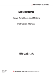
Motion Controller
User's Manual
A173UHCPU, A172SHCPUN,
A171SHCPUN
Art.-no.: 134383
2000 09 01
Version B
INDUSTRIAL AUTOMATION
INTORODUCTION
Thank you for purchasing the Mitsubishi Motion Controller/A173UHCPU/A172SHCPUN/A171SHCPUN.
This instruction manual describes the handing and precautions of this unit. Incorrect handing will lead to
unforeseen events, so we ask that you please read this manual thoroughly and use the unit correctly.
Please make sure that this manual is delivered to the final user of the unit and that it is stored for future
reference.
Precautions for Safety
Please read this instruction manual and enclosed documents before starting installation, operation, maintenance or inspections to ensure correct usage. Thoroughly understand the machine,
safety information and precautions before starting operation.
The safety precautions are ranked as "Warning" and "Caution" in this instruction manual.
WARNING
When a dangerous situation may occur if handling is mistaken
leading to fatal or major injuries.
CAUTION
When a dangerous situation may occur if handling is mistaken
leading to medium or minor injuries, or physical damage.
Note that some items described as cautions may lead to major results depending on the
situation. In any case, important information that must be observed is described.
−I−
For Sate Operations
1. Prevention of electric shocks
WARNING
Never open the front case or terminal covers while the power is ON or the unit is running, as
this may lead to electric shocks.
Never run the unit with the front case or terminal cover removed. The high voltage terminal
and charged sections will be exposed and may lead to electric shocks.
Never open the front case or terminal cover at times other than wiring work or periodic
inspections even if the power is OFF. The insides of the control unit and servo amplifier are
charged and may lead to electric shocks.
When performing wiring work or inspections, turn the power OFF, wait at least ten minutes,
and then check the voltage with a tester, etc. Failing to do so may lead to electric shocks.
Always ground the control unit, servo amplifier and servomotor with Class 3 grounding. Do
not ground commonly with other devices.
The wiring work and inspections must be done by a qualified technician.
Wire the units after installing the control unit, servo amplifier and servomotor. Failing to do
so may lead to electric shocks or damage.
Never operate the switches with wet hands, as this may lead to electric shocks.
Do not damage, apply excessive stress, place heavy things on or sandwich the cables, as
this may lead to electric shocks.
Do not touch the control unit, servo amplifier or servomotor terminal blocks while the power
is ON, as this may lead to electric shocks.
Do not touch the internal power supply, internal grounding or signal wires of the control unit
and servo amplifier, as this may lead to electric shocks.
2. For fire prevention
CAUTION
Install the control unit, servo amplifier, servomotor and regenerative resistor on inflammable
material. Direct installation on flammable material or near flammable material may lead to
fires.
If a fault occurs in the control unit or servo amplifier, shut the power OFF at the servo
amplifier’s power source. If a large current continues to flow, fires may occur.
When using a regenerative resistor, shut the power OFF with an error signal. The regenerative resistor may abnormally overheat due to a fault in the regenerative transistor, etc., and
may lead to fires.
Always take heat measures such as flame proofing for the inside of the control panel where
the servo amplifier or regenerative resistor is installed and for the wires used. Failing to do
so may lead to fires.
− II −
3. For injury prevention
CAUTION
Do not apply a voltage other than that specified in the instruction manual on any terminal.
Doing so may lead to destruction or damage.
Do not mistake the terminal connections, as this may lead to destruction or damage.
Do not mistake the polarity (+/-), as this may lead to destruction or damage.
The servo amplifier's heat radiating fins, regenerative resistor and servo amplifier, etc., will
be hot while the power is ON and for a short time after the power is turned OFF. Do not
touch these parts as doing so may lead to burns.
Always turn the power OFF before touching the servomotor shaft or coupled machines, as
these parts may lead to injuries.
Do not go near the machine during test operations or during operations such as teaching.
Doing so may lead to injuries.
4. Various precautions
Strictly observe the following precautions.
Mistaken handling of the unit may lead to faults, injuries or electric shocks.
(1) System structure
CAUTION
Always install a leakage breaker on the control unit and servo amplifier power source.
If installation of a magnetic contactor for power shut off during an error, etc., is specified in
the instruction manual for the servo amplifier, etc., always install the magnetic contactor.
Install an external emergency stop circuit so that the operation can be stopped immediately
and the power shut off.
Use the control unit, servo amplifier, servomotor and regenerative resistor with the combinations listed in the instruction manual. Other combinations may lead to fires or faults.
If safety standards (ex., robot safety rules, etc.,) apply to the system using the control unit,
servo amplifier and servomotor, make sure that the safety standards are satisfied.
If the operation during a control unit or servo amplifier error and the safety direction
operation of the control unit differ, construct a countermeasure circuit externally of the
control unit and servo amplifier.
In systems where coasting of the servomotor will be a problem during emergency stop,
servo OFF or when the power is shut OFF, use dynamic brakes.
Make sure that the system considers the coasting amount even when using dynamic
brakes.
In systems where perpendicular shaft dropping may be a problem during emergency stop,
servo OFF or when the power is shut OFF, use both dynamic brakes and magnetic brakes.
The dynamic brakes must be used only during emergency stop and errors where servo OFF
occurs. These brakes must not be used for normal braking.
The brakes (magnetic brakes) assembled into the servomotor are for holding applications,
and must not be used for normal braking.
Construct the system so that there is a mechanical allowance allowing stopping even if the
stroke end limit switch is passed through at the max. speed.
Use wires and cables that have a wire diameter, heat resistance and bending resistance
compatible with the system.
− III −
CAUTION
Use wires and cables within the length of the range described in the instruction manual.
The ratings and characteristics of the system parts (other than control unit, servo amplifier,
servomotor) must be compatible with the control unit, servo amplifier and servomotor.
Install a cover on the shaft so that the rotary parts of the servomotor are not touched during
operation.
There may be some cases where holding by the magnetic brakes is not possible due to the
life or mechanical structure (when the ball screw and servomotor are connected with a
timing belt, etc.). Install a stopping device to ensure safety on the machine side.
(2) Parameter settings and programming
CAUTION
Set the parameter values to those that are compatible with the control unit, servo amplifier,
servomotor and regenerative resistor model and the system application. The protective
functions may not function if the settings are incorrect.
The regenerative resistor model and capacity parameters must be set to values that
conform to the operation mode, servo amplifier and servo power unit. The protective
functions may not function if the settings are incorrect.
Set the mechanical brake output and dynamic brake output validity parameters to values
that are compatible with the system application. The protective functions may not function if
the settings are incorrect.
Set the stroke limit input validity parameter to a value that is compatible with the system
application. The protective functions may not function if the setting is incorrect.
Set the servomotor encoder type (increment, absolute position type, etc.) parameter to a
value that is compatible with the system application. The protective functions may not
function if the setting is incorrect.
Set the servomotor capacity and type (standard, low-inertia, flat, etc.) parameter to values
that are compatible with the system application. The protective functions may not function if
the settings are incorrect.
Set the servo amplifier capacity and type parameters to values that are compatible with the
system application. The protective functions may not function if the settings are incorrect.
Use the program commands for the program with the conditions specified in the instruction
manual.
Set the sequence function program capacity setting, device capacity, latch validity range, I/O
assignment setting, and validity of continuous operation during error detection to values that
are compatible with the system application. The protective functions may not function if the
settings are incorrect.
Some devices used in the program have fixed applications, so use these with the conditions
specified in the instruction manual.
The input devices and data registers assigned to the link will hold the data previous to when
communication is terminated by an error, etc. Thus, an error correspondence interlock
program specified in the instruction manual must be used.
Use the interlock program specified in the special function unit's instruction manual for the
program corresponding to the special function unit.
− IV −
(3) Transportation and installation
CAUTION
Transport the product with the correct method according to the weight.
Use the servomotor suspension bolts only for the transportation of the servomotor. Do not
transport the servomotor with machine installed on it.
Do not stack products past the limit.
When transporting the control unit or servo amplifier, never hold the connected wires or
cables.
When transporting the servomotor, never hold the cables, shaft or detector.
When transporting the control unit or servo amplifier, never hold the front case as it may fall
off.
When transporting, installing or removing the control unit or servo amplifier, never hold the
edges.
Install the unit according to the instruction manual in a place where the weight can be withstood.
Do not get on or place heavy objects on the product.
Always observe the installation direction.
Keep the designated clearance between the control unit or servo amplifier and control panel
inner surface or the control unit and servo amplifier, control unit or servo amplifier and other
devices.
Do not install or operate control units, servo amplifiers or servomotors that are damaged or
that have missing parts.
Do not block the intake/outtake ports of the servomotor with cooling fan.
Do not allow conductive matter such as screw or cutting chips or combustible matter such
as oil enter the control unit, servo amplifier or servomotor.
The control unit, servo amplifier and servomotor are precision machines, so do not drop or
apply strong impacts on them.
Securely fix the control unit and servo amplifier to the machine according to the instruction
manual. If the fixing is insufficient, these may come off during operation.
Always install the servomotor with reduction gears in the designated direction. Failing to do
so may lead to oil leaks.
Store and use the unit in the following environmental conditions.
Environment
Ambient
temperature
Ambient humidity
Storage
temperature
Atmosphere
Altitude
Vibration
Conditions
Control unit/servo amplifier
Servomotor
0°C to +55°C
0°C to +40°C
(With no freezing)
(With no freezing)
According to each instruction
80%RH or less
(With no dew condensation)
manual.
According to each instruction
−20°C to +65°C
manual.
Indoors (where not subject to direct sunlight).
No corrosive gases, flammable gases, oil mist or dust must exist
1000m (3278.69ft.) or less above sea level
According to each instruction manual
−V−
CAUTION
When coupling with the synchronization encoder or servomotor shaft end, do not apply
impact such as by hitting with a hammer. Doing so may lead to detector damage.
Do not apply a load larger than the tolerable load onto the servomotor shaft. Doing so may
lead to shaft breakage.
When not using the unit for a long time, disconnect the power line from the control unit or
servo amplifier.
Place the control unit and servo amplifier in static electricity preventing vinyl bags and store.
When storing for a long time, please consult our sales representative.
(4) Wiring
CAUTION
Correctly and securely wire the wires. Reconfirm the connections for mistakes and the
terminal screws for tightness after wiring. Failing to do so may lead to run away of the
servomotor.
After wiring, install the protective covers such as the terminal covers to the original positions.
Do not install a phase advancing capacitor, surge absorber or radio noise filter (option FRBIF) on the output side of the servo amplifier.
Correctly connect the output side (terminals U, V, W). Incorrect connections will lead the
servomotor to operate abnormally.
Do not connect a commercial power supply to the servomotor, as this may lead to trouble.
Do not mistake the direction of the surge absorbing diode
installed on the DC relay for the control signal output of
brake signals, etc. Incorrect installation may lead to signals
not being output when trouble occurs or the protective
functions not functioning.
Do not connect or disconnect the connection cables
between each unit, the encoder cable or sequence expansion cable while the power is ON.
Servo amplifier
VIN
(24VDC)
Control output
signal
RA
Securely tighten the cable connector fixing screws and fixing mechanisms. Insufficient fixing
may lead to the cables combing off during operation.
Do not bundle the power line or cables.
(5) Trial operation and adjustment
CAUTION
Confirm and adjust the program and each parameter before operation. Unpredictable
movements may occur depending on the machine.
Extreme adjustments and changes may lead to unstable operation, so never make them.
When using the absolute position system function, on starting up, and when the controller or
absolute value motor has been replaced, always perform a home position return.
− VI −
(6) Usage methods
CAUTION
Immediately turn OFF the power if smoke, abnormal sounds or odors are emitted from the
control unit, servo amplifier or servomotor.
Always execute a test operation before starting actual operations after the program or
parameters have been changed or after maintenance and inspection.
The units must be disassembled and repaired by a qualified technician.
Do not make any modifications to the unit.
Keep the effect or magnetic obstacles to a minimum by installing a noise filter or by using
wire shields, etc. Magnetic obstacles may affect the electronic devices used near the control
unit or servo amplifier.
When using the CE Mark-compliant equipment, refer to the "EMC Installation Guidelines"
(data number IB(NA)-67339) for the motion controllers and refer to the corresponding EMC
guideline information for the servo amplifiers, inverters and other equipment.
Use the units with the following conditions.
Conditions
Item
A1S61PN
A1S62PN
CPU module's builtin power supply
100 to 240VAC+10%
(85 to 264VAC)-15%
50/60Hz 5%
Input power
Input frequency
Tolerable momentary
power failure
Within 20ms
(7) Remedies for errors
CAUTION
If an error occurs in the self diagnosis of the control unit or servo amplifier, confirm the
check details according to the instruction manual, and restore the operation.
If a dangerous state is predicted in case of a power failure or product failure, use a
servomotor with magnetic brakes or install a brake mechanism externally.
Use a double circuit construction so that the
magnetic brake operation circuit can be
Shut off with the
Shut off with servo ON signal OFF,
operated by emergency stop signals set
emergency stop
alarm, magnetic brake signal.
signal(EMG).
externally.
Servo motor
If an error occurs, remove the cause, secure
RA1
EMG
the safety and then resume operation.
Magnetic
The unit may suddenly resume operation
24VDC
brakes
after a power failure is restored, so do not go
near the machine. (Design the machine so
that personal safety can be ensured even if
the machine restarts suddenly.)
− VII −
(8) Maintenance, inspection and part replacement
CAUTION
Perform the daily and periodic inspections according to the instruction manual.
Perform maintenance and inspection after backing up the program and parameters for the
control unit and servo amplifier.
Do not place fingers or hands in the clearance when opening or closing any opening.
Periodically replace consumable parts such as batteries according to the instruction manual.
Do not touch the lead sections such as ICs or the connector contacts.
Do not place the control unit or servo amplifier on metal that may cause a power leakage or
wood, plastic or vinyl that may cause static electricity buildup.
Do not perform a megger test (insulation resistance measurement) during inspection.
When replacing the control unit or servo amplifier, always set the new unit settings correctly.
When the controller or absolute value motor has been replaced, carry out a home position
return operation using one of the following methods, otherwise position displacement could
occur.
1) After writing the servo data to the PC using peripheral device software, switch on the
power again, then perform a home position return operation.
2) Using the backup function of the peripheral device software, load the data backed up
before replacement.
After maintenance and inspections are completed, confirm that the position detection of the
absolute position detector function is correct.
Do not short circuit, charge, overheat, incinerate or disassemble the batteries.
The electrolytic capacitor will generate gas during a fault, so do not place your face near the
control unit or servo amplifier.
The electrolytic capacitor and fan will deteriorate. Periodically change these to prevent
secondary damage from faults. Replacements can be made by our sales representative.
(9) Disposal
CAUTION
Dispose of this unit as general industrial waste.
Do not disassemble the control unit, servo amplifier or servomotor parts.
Dispose of the battery according to local laws and regulations.
(10) General cautions
CAUTION
All drawings provided in the instruction manual show the state with the covers and safety
partitions removed to explain detailed sections. When operating the product, always return
the covers and partitions to the designated positions, and operate according to the
instruction manual.
− VIII −
Revisions
*The manual number is given on the bottom left of the back cover.
Print Date
*Manual Number
Apr.1998
Sep.2000
IB(NA)-67395-B
IB(NA)-67395-C
Revision
First edition
Addition
Addition of information on the A173UHCPU
Correction
For Sate Operations (4. Various precautions (3), (6), (8)), CONTENTS, 1.1,
1.2.1, 1.2.2, 1.3, 1.4, 1.5.1, 1.5.2 (1), 1.5.3, 1.5.4, 1.5.5, 1.5.6, 2.1, 2.3, 2.3.1,
2.3.2 (2), 4.3, 4.4, 5.4.1, 5.4.1(3), 5.4.1 (4), 5.4.1 (5), APPENDICES
Delete
1.5.7 (2), 5.3.1 (2)
This manual confers no industrial property rights or any rights of any other kind, nor does it confer any patent
licenses. Mitsubishi Electric Corporation cannot be held responsible for any problems involving industrial
property rights which may occur as a result of using the contents noted in this manual.
© 2000 Mitsubishi Electric Corporation
CONTENTS
1. SPECIFICATIONS OF MOTION SYSTEM COMPONENTS..................................................... 1- 1 to 1-57
1.1 Overview of the Motion System ......................................................................................................... 1- 1
1.2 Overall Configuration of Motion System ............................................................................................ 1- 3
1.2.1 A172SHCPUN/A171SHCPUN System Overall Configuration .................................................... 1- 3
1.2.2 A173UHCPU System Overall Configuration ............................................................................... 1- 5
1.3 Equipment in System ......................................................................................................................... 1- 7
1.4 General Specifications ...................................................................................................................... 1-10
1.5 Specifications and Settings of Components ..................................................................................... 1-11
1.5.1 A173UHCPU/A172SHCPUN/A171SHCPUN............................................................................. 1-11
1.5.2 Extension Base Power Supply Module ...................................................................................... 1-25
1.5.3 Base Units and Extension Cables .............................................................................................. 1-28
1.5.4 Manual Pulse Generator/Synchronous Encoder Interface Module............................................ 1-38
1.5.5 Teaching Unit ............................................................................................................................. 1-49
1.5.6 SSCNET Cables and Termination Resistor and Their Connection Method .............................. 1-53
1.5.7 Battery ........................................................................................................................................ 1-57
2. DESIGN...................................................................................................................................... 2- 1 to 2-22
2.1 System Designing Procedure ............................................................................................................ 2- 1
2.2 System Design ................................................................................................................................... 2- 4
2.3 External Circuit Design....................................................................................................................... 2- 5
2.3.1 Power Supply Circuit Design...................................................................................................... 2-10
2.3.2 Safety Circuit Design.................................................................................................................. 2-12
2.3.3 Instructions for External Circuit Wiring Design........................................................................... 2-16
2.4 Layout Design within Enclosure........................................................................................................ 2-17
2.4.1 Location Environment................................................................................................................. 2-17
2.4.2 Installing the Base Units............................................................................................................. 2-18
2.4.3 Installation .................................................................................................................................. 2-19
2.4.4 Calculating Heat Generated by A173UHCPU/A172SHCPUN/A171SHCPUN .......................... 2-20
2.5 Design Checklist ............................................................................................................................... 2-22
3. MOUNTING AND WIRING......................................................................................................... 3- 1 to 3-12
3.1 Mounting and Wiring Methods ........................................................................................................... 3- 1
3.2 Mounting the Base Unit...................................................................................................................... 3- 1
3.2.1 Mounting without DIN Rail........................................................................................................... 3- 2
3.2.2 Mounting with DIN Rail................................................................................................................ 3- 2
3.3 Mounting and Removing Modules ..................................................................................................... 3- 4
3.4 Mounting the Serial Absolute Synchronous Encoder ........................................................................ 3- 7
3.5 Wiring ................................................................................................................................................. 3- 9
3.5.1 How to Run the Power Supply and I/O Wires ............................................................................. 3- 9
3.5.2 Example of Routing the Power Supply and I/O Wires ............................................................... 3-11
3.6 Mounting/Wiring Checklist ................................................................................................................ 3-12
4. TRIAL RUN AND ADJUSTMENT ............................................................................................... 4- 1 to 4- 8
4.1 Checklist before Trial Operation ........................................................................................................ 4- 1
4.2 Trial Run and Adjustment Procedure................................................................................................. 4- 3
−I−
4.3 Operating System Installation Procedure .......................................................................................... 4- 7
4.4 Trial Run and Adjustment Checklist................................................................................................... 4- 8
5. INSPECTION AND MAINTENANCE ......................................................................................... 5- 1 to 5-23
5.1 Maintenance Works ........................................................................................................................... 5- 1
5.2 Daily Inspections ................................................................................................................................ 5- 3
5.3 Scheduled Inspections ....................................................................................................................... 5- 4
5.3.1 Replacing the Battery .................................................................................................................. 5- 5
5.4 Troubleshooting ................................................................................................................................. 5- 7
5.4.1 Troubleshooting for CPU Module and I/O Modules .................................................................... 5- 9
APPENDICES ......................................................................................................................APP- 1 to APP-26
Appendix 1 Cables ............................................................................................................................. APP- 1
Appendix 1.1 SSCNET Cables........................................................................................................ APP- 1
Appendix 1.2 Encoder Cables......................................................................................................... APP- 5
Appendix 1.3 A31TU-E Teaching Unit Cable................................................................................. APP-12
Appendix 2 Outside Dimensions ....................................................................................................... APP-14
Appendix 2.1 CPU Modules .......................................................................................................... APP-14
Appendix 2.2 Pulse Generator/Synchronous Encoder Interface Module (A172SENC)................ APP-16
Appendix 2.3 Main Base Unit ........................................................................................................ APP-17
Appendix 2.4 Extension Base Units .............................................................................................. APP-19
Appendix 2.5 Teaching Unit .......................................................................................................... APP-21
Appendix 2.6 Connector................................................................................................................ APP-23
Appendix 2.7 Manual Pulse Generator Specifications .................................................................. APP-25
Appendix 2.8 Serial Absolute Synchronous Encoder Specifications ............................................ APP-26
− II −
1. SPECIFICATIONS OF MOTION SYSTEM COMPONENTS
1. SPECIFICATIONS OF MOTION SYSTEM COMPONENTS
This chapter provides the system configuration of the motion system and the
specifications, functions, setting methods, external equipment connection
methods, part names and other information of the related modules for those who
are involved in the design, installation, wiring, trial run, adjustment and
maintenance of the motion system.
1.1 Overview of the Motion System
A173UHCPU/A172SHCPUN/A171SHCPUN are CPUs which incorporate the
positioning control CPU (hereinafter referred to as PCPU) and the sequence
control CPU (hereinafter referred to as SCPU) and perform the following functions:
• PCPU..........Carries out the positioning control, home position return, servo
amplifier control status monitoring using a servo program or
motion program.
• SCPU..........Carries out the sequence control, start-up of servo program or
motion program, enabling and disabling manual pulse generator
operation, and jog operation.
Positioning data setting and programming of A173UHCPU/A172SHCPUN/
A171SHCPUN is performed using the following peripheral devices and positioning
software package.
(1) Peripheral device
• IBM PC/AT compatible running DOS/V5.0 or higher(hereinafter abbreviated
as "IBM PC")
(2) Positioning software package
• For IBM PC .........SW SRX-GSV
PE, SW
RN-GSV
PE
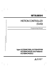
The following diagram outlines the peripheral devices and programs using a
positioning software package, data creation, and A173UHCPU/A172SHCPUN/
A171SHCPUN processing.
[Peripheral device]
IBM PC
+
SW SRX-GSV
SW RN-GSV
+
SW SRX-SV
SW RN-SV
[Program, data]
[A173UHCPU/A172SHCPUN/A171SHCPUN]
Sequence program
Sequence control
Servo program or motion
program execution
PE,
PE
,
SCPU
Positioning
device
Servo program or
motion program
Positioning
parameter
PCPU
JOG operation
For communication
between SCPU and PCPU
Positioning control
Home position return
Servo monitoring
1−1
1. SPECIFICATIONS OF MOTION SYSTEM COMPONENTS
• The sequence program written into the SCPU, the servo program or motion
program written into the PCPU, and the positioning parameters are created
after starting up corresponding positioning software package by the
peripheral device.
• The peripheral device started up by the positioning software package can
monitor the positioning control conditions of A173UHCPU/A172SHCPUN/
A171SHCPUN, execute the servo program or motion program, and perform a
test such as JOG operation.
REMARKS
For information about a peripheral device and programming information for
producing a sequence program and a special function unit, refer to each
manual pertaining to the individual unit.
For information about creating motion programs, refer to the programming
manual of the operating system used. For information about the operation of
each peripheral software package, refer to each individual operating manuals.
In this manual, the following abbreviations are used.
Description
Abbreviation
A173UHCPU/A172SHCPUN/
A173UHCPU/A172SHCPUN/ A171SHCPUN Module
A171SHCPUN or CPU module
MR-H-BN,MR-J2S-B,MR-J2-B servo amplifier
MR-H-BN/MR-J2S-B/MR-J2-B
A172SENC manual pulse generator/synchronous encoder interface unit/module
A172SENC
Fast serial communication between motion controller and servo amplifier
SSCNET*1
*1 SSCNET: Servo System Controller NETwork
1−2
1. SPECIFICATIONS OF MOTION SYSTEM COMPONENTS
1.2 Overall Configuration of Motion System
1.2.1 A172SHCPUN/A171SHCPUN System Overall Configuration
*1
Motion CPU
A6BAT
A172 A1S
SENC Y42
A1S input module or
special function module
Emergency stop input
Extension cable
(A1SC B for
A1S6 B
and A168B)
(A1S NB
for A6 B)
Main base unit(A178B-S1/A17
100/200VAC
IBM PC
(DOS)
B)
P
Manual pulse generator 1
(MR-HDP01)
E
Serial absolute synchronous encoder cable
(MR-HSCBL M)
Serial absolute synchronous encoder 1
(MR-HENC)
RS422
GOT
Power supply
module
Manual pulse generator/
synchronous encoder
interface module
Battery
Sequence module slot
Limit switch
output module
Motion slot
Sequence extension base
Up to one extension base unit for A1S6 B
Up to one extension base unit for A168B
(GOT compatible)
Up to one extension base unit for A6 B
A171SHCPUN A172SHCPUN
External input signals
Teaching unit
A31TU-E/A30TU-E
RS422
Communication cable
(A270CDCBL M/
A270BDCBL M)
IBM PC (DOS,Windows)
FLS upper stroke limit
RLS lower stroke limit
STOP signal
DOG/CHANGE near-zero point dog/
changeover between speed and position
4
8
TRA tracking
1
1
Electromagnetic brake command output
SSCNET2
SSCNET cable
d1
SSC I/F card/board
(A30CD-PCF/A30BD-PCF)
d2
d3
dn
*2
Termination
resistance
SSCNET1
*1:No. of motion slots
A17 B
A178B-S1
1
2
M
M
M
M
E
E
E
E
*2:n:No. of control axes (max.)
A171SHCPUN 4
A172SHCPUN 8
MR-H-BN/MR-J2S-B/MR-J2-B model
Servo amplifier
SSCNET:Servo System Controller NETwork
POINTS
(1) When using the sequence extension base and bus connection type GOT, select the A168B as the
sequence extension base. When not using the sequence extension base, you can connect the bus
connection type GOT directly to the extension connector of the main base unit.
(2) When using a teaching unit A31TU-E with a dead-man switch, a dedicated connecting cable
A31TUCBL03M is required between the CPU unit and A31TU-E connector. If the A31TU-E is
connected directly to the RS422 connector of the CPU without using a dedicated cable, the
A31TU-E will not operate at all. After disconnecting the A31TU-E, attach a short-circuit connector
A31SHORTCON for A31TUCBL.
(3) In a motion module, a sequence A1S I/O modules can also be installed.
(4) Though the external input signals of A172SENC are reserved for eight axes, for A171SHCPUN,
set those for the first half four axes (PX0 to PX0F).
1−3
1. SPECIFICATIONS OF MOTION SYSTEM COMPONENTS
CAUTION
Configure safety circuits external to the controller or servo amplifier if their abnormal operation
could cause axis motion in a direction other than the safe operating direction for the system.
Ensure that the characteristics of other components used in a system match those of the
controllers, servo amplifiers, and servo motors.
Set the parameters to values appropriate for the controllers, servo amplifiers, servo motors,
regenerative resistor types, and system application. The protective functions may not work if the
parameters are set incorrectly.
1−4
1. SPECIFICATIONS OF MOTION SYSTEM COMPONENTS
1.2.2 A173UHCPU System Overall Configuration
*1
Sequence module slot
Main base unit
(A178B-S3/
A178B-S2/
A178B-S1/
A17 B)
Manual pulse
generator/
synchronous encoder
interface module
Battery
A173UHCPU A172 A172 A172 A172
SENC SENC SENC SENC
A6BAT
Emergency stop input
A1S input module or
special function module
P
100/200VAC
Manual pulse generator 3
(MR-HDP01)
P
IBM PC
(DOS)
Extension cable
(A1SC B for
A1S6 B
and A168B)
(A1S NB
for A6 B)
P
E
E
E
Teaching unit
A31TU-E/A30TU-E
Sequence extension base
Up to one extension base unit for A1S6 B
Up to one extension base unit for A168B
(GOT compatible)
Up to one extension base unit for A6 B
Serial absolute synchronous
encoder cable
(MR-HSCBL M)
Serial absolute synchronous encoder
(MR-HENC)
E
RS422
GOT
Power supply
module
Motion slot
4
External input signals
FLS upper stroke limit
RLS lower stroke limit
STOP signal
DOG/CHANGE near-zero point dog/
speed-position change
RS422
Communication cable
(A270CDCBL M/
A270BDCBL M)
TRA tracking
IBM PC (DOS,Windows)
*3
8
8
8
8
1
1
1
1
Electromagnetic brake command output
*2
*2
SSCNET4
SSCNET4
SSCNET cable
SSCNET3
SSC I/F card/board
(A30CD-PCF/A30BD-PCF)
SSCNET2
d1
d9
d8
d17
d16
d25
d24
d32
SSCNET1
*1:No. of motion slots
A17 B
A178B-S1
A178B-S2
A178B-S3
1
2
4
8
M
E
M
M
E
E
M
M
E
E
M
M
M
E
E
E
MR-H-BN/MR-J2S-B/MR-J2-B model
Servo amplifier, max. 32 axes
SSCNET:Servo System Controller NETwork
POINTS
(1) When using the sequence extension base and bus connection type GOT, select the A168B as the
sequence extension base. When not using the sequence extension base, you can connect the bus
connection type GOT directly to the extension connector of the main base unit.
(2) When using a teaching unit A31TU-E with a dead-man switch, a dedicated connecting cable
A31TUCBL03M is required between the CPU unit and A31TU-E connector. If the A31TU-E is
connected directly to the RS422 connector of the CPU without using a dedicated cable, the
A31TU-E will not operate at all. After disconnecting the A31TU-E, attach a short-circuit connector
A31SHORTCON for A31TUCBL.
(3) In a motion module, a sequence A1S I/O modules can also be installed.
*2 The A173UHCPU can use four channels of the SSCNET. When using the SSCNET card/board
(A30CD-PCF/A30BD-PCF), connect it to the SSCNET4 and the servo amplifiers to the SSCNET1
to 3.
In this case, up to 24 axes of servo amplifiers can be connected.
*3 TRA tracking enable can use any one point.
1−5
1. SPECIFICATIONS OF MOTION SYSTEM COMPONENTS
CAUTION
Configure safety circuits external to the controller or servo amplifier if their abnormal operation
could cause axis motion in a direction other than the safe operating direction for the system.
Ensure that the characteristics of other components used in a system match those of the
controllers, servo amplifiers, and servo motors.
Set the parameters to values appropriate for the controllers, servo amplifiers, servo motors,
regenerative resistor types, and system application. The protective functions may not work if the
parameters are set incorrectly.
1−6
1. SPECIFICATIONS OF MOTION SYSTEM COMPONENTS
1.3 Equipment in System
(1) Table of motion modules
Part Name
CPU module
Model Name
Description
A173UHCPU(-S1)
A172SHCPUN
A171SHCPUN
A172B
A175B
Max. 32 axes control
Max. 8 axes control
Max. 4 axes control
One motion module slot and one sequence module slot
One motion module slot and four sequence module slots
One motion module slot and seven sequence module
slots
Two motion module slots and six sequence module slots
Four motion module slots and four sequence module slots
Eight motion module slots and zero sequence module
slots
Extension power and five slots for system up to one
extension stage
Extension power and eight slots for system up to one
extension stage
Extension power and eight slots for system up to one
extension stage
A178B
Main base unit
A178B-S1
A178B-S2
A178B-S3
A1S65B
Sequence
extension base
unit
A1S68B
A168B
A1SC01B
Length 330 mm (13 in)
Length 700 mm (27 in)
Length 1200 mm (47 in)
Length 3000 mm (118 in)
Length 6000 mm (236 in)
Length 450 mm (17 in) AnN extension base cables
Length 700 mm (27 in) AnN extension base cables
Length 3000 mm (118 in) AnN extension base cables
Length 5000 mm (197 in) AnN extension base cables
Manual pulse
generator
/synchronous
encoder
interface
module
32 points I/O signals
(FLS, RLS, STOP, DOG/CHANGE×8)
Tracking input 1 point
Electromagnetic brake control output 1 point
Manual pulse generator interface 1 point
Synchronous encoder interface 1 point
A172SENC
A1SY42
Transistor output 64 points, 12/24 VDC, 0.1A
4.5 VDC to 13.2 VDC 25 PLS/rev, 100 PLS/rev at
magnification of 4
MR-HDP01
0.93
0.06
0.22
A31TUCBL03M
A31SHORTCON
Short-circuit connector for A31TUCBL
A30BD-PCF
A30CD-PCF
ISA bus loading type, 2 channels/board
PCMCIA TYPE II, 1 channel/card
3 m (9.84 ft.), 5 m (16.4 ft.), 10 m (32.8 ft.) for
A30BD-PCF
3 m (9.84 ft.), 5 m (16.4 ft.), 10 m (32.8 ft.) for
A30CD-PCF
Battery
A6BAT
M
A30TU-E
A31TU-E
A31TU-RE
A270BDCBL
M
A270CDCBL
M
1−7
B
0.42
Synchronous encoder and A172SENC connector cables:
2 m (6.56 ft.), 5 m (16.4 ft.), 10 m (32.8 ft.), 20 m (65.6
ft.), 30 m (98.4 ft.)
(Same cables as encoder cables for HA-LH K, HCSF/RF/UF(2000r/min)series motors.)
For CPU module memory back-up
(Sequence program/servo program)
For SV13, cable length 5 m (16.4 ft)
For SV13 with deadman switch, cable length 5 m (16.4
ft)
For SV51 with deadman switch, cable length 5 m (16.4
ft)
(Need A31TUCBL03M and A31SHORTCON.)
CPU module to A31TU-E connector cable of 3 m (9.84 ft.)
MR-HSCBL
SSC I/F board
SSC I/F card
SSC I/F board
cable
SSC I/F card
cable
For A6
0.15
Serial absolute
synchronous
encoder cable
Teaching unit
Extension connector
as accessory
For extension to the
right side
Resolution: 16384 PLS/rev,
Permitted rotational speed: 4300r/min
MR-HENC
Remarks
Sequence extension
connector as
accessory
Flat cable of 55 mm (2.17 in) in length
A1SC03B
A1SC07B
A1SC12B
Extension cable A1SC30B
A1SC60B
A1SC05NB
A1SC07NB
A1SC30NB
A1SC50NB
Limit output unit
Manual pulse
generator
Serial absolute
synchronous
encoder
Current
Consumption
5 VDC (A)
1.90
1.63
1.63
0.22
0.22
For control panel
When A31TU-E is
not connected
1. SPECIFICATIONS OF MOTION SYSTEM COMPONENTS
(2) Table of servo amplifier modules
Part Name
MR-H-BN
series
MR-J2S-B
series
MR-J2-B
series
Model Name
MR-H BN
Servo amplifier
MR-H KBN
Battery
MR-BAT
Termination
MR-TM
connector
MR-PB
MR-H KB
Regenerative
Standard accessory
resistor
MR-PB -4
FR-BU
FR-RC
Description
50 W to 22 kW
30 kW to 55 kW
Backup for absolute position detection
Fitted to the last amplifier of SSCNET
External regenerative resistor 10 W to 500 W
Regenerative power 600 W
External regenerative resistor 1300, 3900 W
Brake unit 15/30/55K
Power return converter 15/30/55K
For connection of CPU module and MR-H-BN, for connection of MR-H-BN and
SSCNET cable MR-HBUS M
MR-H-BN
0.5 m(1.64 ft), 1 m (3.28ft), 5 m (16.4 ft)
For connection of HA-LH K, HC-SF/RF/UF (2000r/min) series motor and MR-HMR-HSCBL M
Encoder cable
BN
*2
MR-EN1CBL M-H
2 m (16.4 ft), 5 m (16.4 ft), 10 m (32.8 ft), 20 m (65.6 ft), 30 m (98.4 ft)
MR-JSCNS
Encoder
For HA-LH K, HC-SF/RF/UF (2000r/min) series motors
connector set
MR-EN1CNS
Amplifier side connector and encoder side connector set
*1
50 W to 7 kW, three-phase 200 to 230 VAC or single-phase 230 VAC
MR-J2S- B
Servo amplifier
50 W to 400 W, single-phase 100 to 120 VAC
MR-J2S- B1
Servo amplifier MR-J2Battery
Termination
connector
B
MR-BAT
Backup for absolute position detection
MR-A-TM
Fitted to the last amplifier of SSCNET
MR-J2HBUS
SSCNET cable
MR-J2HBUS
Equipment
common to
MR-J2S-B
and
MR-J2-B
Encoder
*2
series
MR-JHSCBL
MR-JHSCBL
cable
MR-ENCBL
MR-JCCBL
MR-JCCBL
Encoder
connector set
50 W to 3.5 kW
MR-J2CNS
MR-ENCNS
MR-J2CNM
For connection of CPU module and MR-J2S-B/MR-J2-B, for connection of MR-HM-A BN and MR-J2S-B/MR-J2-B
0.5 m(1.64 ft), 1 m (3.28ft), 5 m (16.4 ft)
For connection of MR-J2S-B/MR-J2-B and MR-J2S-B/MR-J2-B
M
0.5 m(1.64 ft), 1 m (3.28ft), 5 m (16.4 ft)
For connection of HC-SFS/RFS/UFS (2000r/min) series motor and
Standard
M-L cable
MR-J2S-B, and for connection of HC-SF/RF/UF (2000r/min) series
M-H Long flexing motor and MR-J2-B
2 m (6.56 ft), 5 m (16.4 ft), 10 m (32.8 ft), 20 m (65.6 ft),
M-H life cable
30 m (98.4 ft)
For connection of HC-MFS/KFS/UFS (3000r/min) series motor and
Standard
M-L
MR-J2S-B, and for connection of HC-MF/UF (3000r/min), HA-FF
cable
series motor and MR-J2-B
Long flexing
2 m (6.56 ft), 5 m (16.4 ft), 10 m (32.8 ft), 20 m (65.6 ft),
M-H
life cable
30 m (98.4 ft)
For HC-SF/RF/UF (2000r/min), HC-SFS/RFS/UFS (2000r/min) series motors
Amplifier side connector and encoder side connector set
For HC-MF/UF (3000r/min), HA-FF, HC-MFS/KFS/UFS (3000r/min) series motors
Amplifier side connector and encoder side connector set
*1: 5kW and 7kW are scheduled for release.
*2: Long distance cable or cable without connector (cable only) is also available.
Avoid using a short cable as it will cause a position shift or the like.
1−8
1. SPECIFICATIONS OF MOTION SYSTEM COMPONENTS
(3) Table of software package
(a) Motion function
Peripheral Software Package
Use
DOS
assembly
IBM PC/AT
NT/
(SV13)
98
For motion
conveyor
For
A172SH/
A171SH
For
For
For
A173UH
A172SH
A171SH
Japanese SW2SRX-GSV13P
From 0AC on 00T or later
SW2SRX-
SW0SRX-
SW0SRX-
English
From 00J on
00F or later
SV13B
SV13D
SV13G
From 00F on
00E or later
Without
Without
SW2SRX-
SW2SRX-
SW0SRX-
restriction
restriction
SV13B
SV13D
SV13G
Model Name
SW2SRX-GSV13PE
Japanese SW3RNC-GSV
English
SW3RNC-GSVE
Japanese SW3RNC-GSV
SFCcompatible
Applicable version
Peripheral
Devices
For conveyor
IBM PC/AT
Main OS Software Package Model Name
For
A173UH
From 00F on
Yes
Without
restriction
NT/
SW3RN-
SW3RN-
98
SV13B
SV13D
English
assembly
SW3RNC-GSVE
Teaching
function
Without
Without
restriction
restriction
(SV13)
Japanese
DOS
For automatic
machinery
English
IBM PC/AT
SW2SRX-GSV22P
From 00B on
00B or later
SW2SRX-GSV22PE
From 00J on
00F or later
Without
Without
SW2SRX-
SW0SRX-
SW0SRX-
restriction
restriction
SV22A
SV22C
SV22F
From 00F on
00E or later
Without
Without
restriction
restriction
SW0IX-CAMPE
(SV22)
NT/
98
For motion
automatic
machinery
SW3RNC-GSVE
Japanese SW3RNC-GSV
SFCcompatible
Japanese SW3RNC-GSV
English
IBM PC/AT
From 0AC on 00T or later
SW0SRX-CAMP
From 00F on
Without
restriction
NT/
98
English
SW3RNC-GSVE
No
Without
Without
restriction
restriction
From 00T on
00J or later
SW3RN-
SW3RN-
SV22A
SV22C
SW2SRX-
SW0SRX-
SW0SRX-
SV43A
SV43C
SV43F
SW0SRX-
SW0SRX-
SV51D
SV51G
(SV22)
For machine
tool peripheral IBM PC/AT DOS Japanese SW2SRX-GSV43P
(SV43)
For dedicated
robot (SV51)
IBM PC/AT DOS Japanese SW2SRX-GSV51P
00E or later
1−9
No
Yes
1. SPECIFICATIONS OF MOTION SYSTEM COMPONENTS
1.4 General Specifications
Table 1.1 Generation Specifications
Item
Specification
Operating ambient
0 to 55°C
temperature
Storage ambient
-20 to 75°C
temperature
Operating ambient
10% to 90%RH, no condensation
humidity
Storage ambient
10% to 90%RH, no condensation
humidity
Frequency
Vibration resistance
Conforms to JIS C
0911*2
Acceleration
Noise resistance
Number of Sweeps
0.075mm
10 to 55Hz
(0.003 in)
9.8m/s2
55 to 150Hz
Shock resistance
Amplitude
10
(1 octave/minute)*1
Conforms to JIS C 0912 (98m/s2 (10g), 3 directions, 3 times)*2
(1) Noise voltage: 1500Vpp, noise amplitude: 1µs, noise frequency: 25 to 60 Hz, with a noise simulator
(2) Noise voltage : IEC801-4, 2 kV
Withstand voltage
2830VAC rms/3 cycles across all inputs/LG and all outputs/FG (altitude 2000m (6557.38ft.))
Insulation resistance
5M
Ground
Class 3 grounding. Connect to enclosure when grounding is impossible.
or more by 500VDC insulation resistance tester across all inputs/LG and all outputs/FG
Operating environment
No corrosive gas, low dust
Cooling method
Natural cooling.
REMARKS
*1 An “octave” refers to an increase or decrease in frequency by a factor of
two. For example, the following are all octaves: 10 Hz to 20 Hz, 20 Hz to
40 Hz, 40 Hz to 20 Hz, and 20 Hz to 10 Hz.
Refer to “CHAPTER 2 DESIGN” for the installation environment and
mounting instructions.
*2 JIS: Japan Industrial Standards
WARNING
Class 3 grounding should be used. The motion controller should not share a common ground with
any other equipment. The ground terminal is located on the motion controller module terminal
block. (See Section 1.5.2.)
CAUTION
The motion controller must be stored and operated under the conditions listed in the table of
specifications above.
Disconnect the power cables from the motion controller if it is to remain unused for a long period
of time.
Insert a controller or servo amplifier into the static-proof vinyl bag for storage.
Consult the system service or service station before storing equipment for a long period of time.
1 − 10
1. SPECIFICATIONS OF MOTION SYSTEM COMPONENTS
1.5 Specifications and Settings of Components
1.5.1 A173UHCPU/A172SHCPUN/A171SHCPUN
(1) Basic specifications of A173UHCPU, A172SHCPUN and A171SHCPUN
Item
A173UHCPU(-S1)
A172SHCPUN
A171SHCPUN
32-axes
3.5 ms/1 to 20 axes
7.1 ms/21 to 32 axes
8-axes
4-axes
3.5 ms/1 to 12 axes
7.1 ms/13 to 24 axes
14.2 ms/25 to 32 axes
3.5 ms/1 to 8 axes
3.5 ms/1 to 4 axes
Equivalent to
reinforced I/O
memory of
A2SHCPU
Equivalent to
A2SHCPU
No. of control axes
SV13
Motion
Computing
frequency
SV22
Sequencer CPU
Processing speed
( s) (Sequence
instruction)
Equivalent to A3UCPU
Direct
method
Refresh
method
0.25 to 1.9 s/step
0.15 s/step
No. of I/O points
No. of real I/O points *1
PC
Standard
Memory capacity (built-in RAM)
-S1
Program capacity
(Main sequence)
No. of file register (R)
No. of extension file register
block *2
8192 points
2048 points
192k bytes (Equivalent to
A3NMCA-24)
768k bytes (Equivalent to
A3AMCA-96)
Max. 30k steps
System
configuration
No. of SSCNET I/F
Teaching unit (OS A30TU-E
with teaching
A31TU-E
function)
Sequence program, parameter
Servo program
Mechanism program (SV22)
Parameter
Outside dimensions
192k bytes
(Equivalent to
A3NMCA-24)
64k bytes
(Equivalent to
A3NMCA-8)
Max. 30k steps
Max. 14k steps
Max. 2 blocks
Max. one
A172SENC 4
(Corresponding to external signal input
32-axes)
4CH.
A172SENC 1
(Corresponding to external signal input
8-axes)
2CH.
SSCNET1..... For connection of servo
amplifier
SSCNET2..... For personal computer link
dedicated
(With dead-man switch)
After starting A173UHCPU and reading After starting A172SH/A171SH and
a file, those created by A273UHCPU
reading a file, those created by
(32-axes) can be used as it is.
A171SCPU can be used as it is.
By making sure of system setting screen
after being started up by A172SH/A171SH
and reading a file, changeover below is
carried out:
A172SH/A171SHCPUN
A171SCPU
A171SENC
A172SENC
now the system is ready for operation.
Compatibility
System setting
2048 points
1024 points
512 points
Max. 8192 registers
Max. 10 blocks
Max. 10 blocks
Max. 46 blocks
Standard
-S1
No. of sequencer extension
base units
Pulser synchronous encoder
interface unit
0.25 s/step
Must be set anew.
130
113.3
Weight (kg (lb))
93.6 (5.12 4.46
3.69) unit = mm (inch)
0.85 (1.87)
*1 The real I/O points can be used within the range of one extension base.
*2 No. of extension file register blocks varies depending on the setting of program capacity, No. of file
registers, and No. of comments.
1 − 11
1. SPECIFICATIONS OF MOTION SYSTEM COMPONENTS
(2) Functions and performance specifications of PCPU
The performance specifications and functions of the PCPU depend on the
motion function OS model installed in the CPU module.
Refer to the programming manual of the motion functions installed in the CPU
module.
1 − 12
1. SPECIFICATIONS OF MOTION SYSTEM COMPONENTS
(3) SCPU performance specifications and functions
(a) SCPU performance specifications
As the SCPU performance specifications differ according to the operating
system used, refer to the appropriate OS Programming Manual for details.
Table 1.2 Table of SCPU Performance Specifications
Item
Control method
I/O control method
Programming language
Number of instructions
Processing speed ( s)
(sequence instructions)
No. of I/O points
Sequence instructions
Basic instructions
Special instructions
Motion dedicated instructions
Direct method
Refresh method
No. of real I/O points *5
Watchdog timer (WDT)
Memory capacity (internal RAM)
Program capacity
Main sequence program
Sub-sequence program
Micro computer program
No. of internal relays (M) *1
No. of latch relays (L)
No. of step relays (S)
No. of link relays (B)
Points
Timers (T)
Specifications
A173UHCPU(-S1)
A172SHCPUN
A171SHCPUN
Stored programs repeated operation
Refresh method
Refresh method/direct method (selectable)
Sequence control dedicated language
(Relay symbol language, logic symbol language, MELSAP-II (SFC))
22
26
252
131
204
106
4
4
0.25 to 1.9 s/step
0.15 s/step
0.25 s/step
8192 points (X/Y0 to 1FF)
2048 points (X/Y0 to X/Y7FF)
1024 points (X/Y0 to
2048 points (X/Y0 to 7FF)
512 points (X/Y0 to X/Y1FF)
X/Y3FF)
200 ms fixed
10 to 2000 ms
192k bytes
Standard
(Equivalent to
A3NMCA-24)
192k bytes
64k bytes
768k bytes
-S1
(Equivalent to
A3AMCA-96)
Max. 30 k steps
Max. 14k steps
Max. 30k steps
None
None
None
Max. 58k bytes
Max. 26k bytes
7144 points (M0 to M999,
1000 points (M0 to M999)
M2048 to M8191)
1048 points (L1000 to L2047)
0 point (none at initial status)
8192 points (B0 to B1FFF)
1024 points (B0 to B3FF)
256 points
*3
Time setting
Device
100 ms timer
0.1 to 3276.7s
T0 to T199
10 ms timer
0.01 to 327.67s
T200 to T255
100ms retentive timer
0.1 to 3276.7s
No initial value
Set with parameters
Points
256 points
*4
Device
Counters (C)
Normal counter
Setting range
1 to 32767
Interrupt program counter
1 to 32767
Device
C0 to C255
C224 to C255
(No initial value)
Specifications
Set with parameters
No. of data registers (D) *1
No. of link registers (W)
No. of annunciators (F)
No. of file registers (R)
No. of accumulators (A)
8192 points (D0 to D8191)
1024 points (D0 to D1024)
8192 points (W0 to W1FFF)
1024 points (W0 to W3FF)
2048 points (F0 to F2047)
256 points (F0 to F255)
Max. 8192 points (R0 to R8191) (set with parameters)
2 points (A0, A1)
14 points
No. of index registers (V, Z)
2 points (V, Z)
(V, V1 to V6, Z, Z1 to Z6)
No. of pointers (P)
No. of interrupt pointers (I)
No. of special-function relays(M)
No. of special-function registers (D)
256 points (P0 to P255)
32 points (I0 to I31)
256 points (M9000 to M9255)
256 points (D9000 to D9255)
1 − 13
1. SPECIFICATIONS OF MOTION SYSTEM COMPONENTS
Table 4.1 Table of SCPU Performance Specifications (Continued)
Item
No. of extension file register block
No. of comments
No. of extension comments *2
Self-diagnosis function
Operating mode on error
Output mode selection when switching from STOP to RUN
Clock function
A173UHCPU (-S1)
A172SHCPUN
A171SHCPUN
Max. 10 blocks
Standard (set by memory
*6
*6
capacity)
Max. 3 blocks
Max. 10 blocks
(set by memory capacity)
(set by memory capacity)
Max. 46 blocks
-S1
(set by memory
capacity)
Max. 4032 points (64k bytes), 1 point = 16 bytes (set in 64-point unit)
Max. 3968 points (63k bytes), 1 point = 16 bytes (set in 64-point unit)
Watchdog error monitoring, memory/CPU/input output/battery, etc. error detection
Select stop/continue
Select re-output operation status before STOP (default) or output after operation
execution.
Year, month, day, hour, minute, day of the week (leap year automatic distinction)
*1 Range of positioning dedicated devices differs depending on the OS. Refer to the Programming Manual of each OS.
When shared between M, L and S, the total number of devices points is 8192 for the A173UHCPU or 2048 for the A172SHCPUN/A171SHCPUN.
*2 Extension comments are not stored into the internal memory of the CPU.
*3 For the A173UHCPU, set the times of the extension timers (T256 to T2047) using the word devices (D, W, R).
*4 For the A173UHCPU, set the count values of the extension counters (C256 to C1023) using the word devices (D, W, R).
*5 The real I/O points can be used within the range of one extension base.
*6 SW0GHP-UTLP-FN1 is necessary for using A6GPP and A6PHP.
1 − 14
1. SPECIFICATIONS OF MOTION SYSTEM COMPONENTS
(b) SCPU functions
Refer to the A2SHCPU user's manual for details of the SCPU functions of
A171SHCPUN/A172SHCPUN and A3UCPU user’s manual for details of
the SCPU functions of A173UHCPU.
Table 1.3 Table of SCPU Functions
Function
Description
! Sets a constant time for one scan of a sequence program which is independent of the sequence
Constant scan
program scan.
! Set the constant scan time between 10 ms and 2000 ms.
Latch (hold on
power interruption)
Remote
RUN/STOP
! The contents of devices set as latch devices are retained when a reset or a power interruption
over 20 ms occurs if the power is turned off.
! Devices L, B, T, C, D, W can be set as latch devices.
! Conducts remote RUN/STOP sequence control from external inputs or peripheral devices when
the RUN/STOP switch is set to RUN.
! Stops the operation and holds the output (Y) ON/OFF status.
PAUSE
! The PAUSE status can be set by two method:
! With the remote PAUSE contacts
! From a peripheral device
! The contents of all devices are written to the CPU module status latch area when the status
Status latch
latch conditions are met.
! The contents of the devices stored in the status latch area can be monitored from a peripheral
device.
! The operating status of the designated device is sampled at the set interval, and the results are
Sampling trace
stored in the CPU module sampling trace area.
! Data stored in the sampling trace area can be monitored from a peripheral device.
Off-line switch
Error indicator
order or priority
! Separates the devices (Y, M, L, S, F, B) used by the OUT instruction from the sequence
program operations.
! Sets order in which the indicators light and go out when an error occurs.
! Executes the CPU module internal clock operations.
Clock
! Clock data is: year, month, day, hour, minute, second, day of week.
! The clock data can be read to D9025 to D9028.
1 − 15
1. SPECIFICATIONS OF MOTION SYSTEM COMPONENTS
(4) Names of A173UHCPU/A172SHCPUN/A171SHCPUN Parts
A173UHCPU/A172SHCPUN
3)
2)
1)
13)
15)
16)
N
12)
N
4)
100 240VAC
105VA
100 240VAC
105VA
10)
14)
NC
NC
6)
17)
7)
8)
9)
[A173UHCPU]
18), 19)
FRONT
SSCNET
4
1
3
2
11)
19)
18)
19)
18)
1:SSCNET1 2:SSCNET2
3:SSCNET3 4:SSCNET4
A171SHCPUN
2)
3)
1)
13)
15)
16)
N
100 240VAC
105VA
4)
3
24VDC 0.6A
100 240VAC
105VA
3
24VDC 0.6A
10)
14)
+24V
5)
12)
N
24G
6)
17)
7)
8)
9)
18), 19)
No.
11)
Name
1)
RUN/STOP key switch
2)
POWER indicator
Application
! RUN/STOP: Starts or stops operation of a sequence program.
! RESET: Resets the hardware.
Applies a reset after an operation error occurs and initializes the operations.
! LATCH CLEAR (L. CLR): Clears the latch area data set with the parameters
(to OFF or 0).
(LATCH CLEAR also clears data outside the latch area.)
! Display indicator for 5 VDC power supply.
1 − 16
1. SPECIFICATIONS OF MOTION SYSTEM COMPONENTS
No.
Name
3)
RUN indicator
4)
ERROR indicator
5)
24 VDC, 24 GDC
terminals
6)
FG terminal
7)
LG terminal
Power supply input
8)
terminals
9) Terminal screws
10) Terminal cover
11) RS-422 connector
12) Covers
13) Module fixing screws
14) Battery
15) DIP switch 1
16) DIP switch 402
Applications
! Lit: Sequence program operating with RUN/STOP key switch set to RUN.
The indicator remains lit if an operation error occurs in the sequence
program (Refer to section 5.4.1 (10)).
! Not lit: The RUN indicator is not lit in the following cases:
! No 100/200 VAC power supplied to the CPU module.
! RUN/STOP key switch is set to STOP.
! A remote STOP is applied.
! A remote PAUSE is applied.
! Flashing: The RUN indicator flashes in the following cases:
! Self-diagnosis function detected an error which stops sequence
program
operation.
! A latch clear operation is conducted.
! Lit: Self-diagnosis function detected an error.
However, the indicator does not light if it is set not to light for the error
detected in the order of priority settings.
! Not lit: Normal, or error detected by CHK instruction.
! Flashing: Sequence program annunciator (F) is on.
! Internally supplies output modules which require 24 VDC (supplied through external
wiring). (A171SHCPUN only)
! A grounding terminal connected with the shielding pattern on the printed circuit
board.
! Ground for power supply filter, with 1/2 the electrical potential of the input voltage.
! Connect the 100 VAC or 200 VAC power supply to the power supply input
terminals.
! M3.5 7
! A cover to protect the terminal block.
! Connector to read, write, monitor, or test main programs with a peripheral device.
! Covered by a cover when not connected to a peripheral device.
! Open the protective cover for the printed circuit board, RS-422 connector, or
battery to carry out the following operations:
! Set DIP switches.
! Connect the battery connectors.
! Replace the battery.
! Screws to fix the module to the base unit.
! Back-up battery for programs, devices in the latch range, and file registers.
(See Section 1.5.7 for the battery mounting procedure.)
! Installation switch
This switch is used to change the installed CPU module operating system with a
peripheral device.
(See Section 1.5.1 (5) for details about the switch settings.)
ON : Turn ON to install an operating system.
OFF : Turn OFF to enable CPU operation when OS installation is complete.
! This switch selects the I/O control method and enables or disables memory
protection.
(See Section 1.5.1 (5) for details about the switch settings.)
! A connector for connecting the battery unit
17) Battery connector
Motion network connector
SSCNET1 to 2
(A172SHCPUN/
! Connectors to HR-H-BN/MR-J2S-B/MR-J2-B.
18)
A171SHCPUN)
SSCNET1 to 4
(A173UHCPU)
1 − 17
1. SPECIFICATIONS OF MOTION SYSTEM COMPONENTS
No.
Name
Personal computer link
SSC connector
SSCNET2
19) (A172SHCPUN/
A171SHCPUN)
SSCNET4
(A173UHCPU)
Applications
! A connector for linking a personal computer and personal computer link SSC.
When using the A172SHCPUN/A171SHCPUN, connect the servo amplifier or
personal computer to SSCNET2, or when using the A173UHCPU, connect it to
SSCNET4.
1 − 18
1. SPECIFICATIONS OF MOTION SYSTEM COMPONENTS
(5) Switch settings
SW1
ON
OFF
1
Operation mode setting
2
ON : Installation
OFF: Ordinary operation
Not used
SW402
For A172SHCPUN/A171SHCPUN
Not used
I/O control method setting
2
4
OFF
3
ON
1
ON : Direct method for inputs and outputs
OFF: Refresh method for inputs and outputs
1 2
SCPU built-in RAM memory protect range setting
Less than a range from 64k to 256k bytes
Less than a range from 0k to 64k bytes
ON : Memory protect ON
OFF: Memory protect OFF
* SW402-2 is invalid for A171SHCPUN.
* Memory allocation varies depending on the PC memory capacity
setting.
SW402
OFF
For A173UHCPU
SCPU built-in RAM memory protect range setting
1 2 3 4
2
3
4
ON
1
A17 SHCPUN
More than 144k bytes
Less than a range from 64k to 144k bytes
Less than a range from 32k to 64k bytes
Less than a range from 0k to 32k bytes
ON : Memory protect ON
OFF: Memory protect OFF
* Memory allocation varies depending on the PC memory capacity
setting.
1 − 19
1. SPECIFICATIONS OF MOTION SYSTEM COMPONENTS
CAUTION
Switch SW1-2 is for use by the manufacturer only.
Leave this switch set OFF.
Operation cannot be guaranteed if this switch is set to ON.
POINTS
(1) Turn off the power supply before setting the install switch.
(2) After using this switch, check the switch status before turning on the power supply.
(3) The switch settings shipped from the factory are as shown above. The switch settings are
indicated by a mark ( ).
(4) Whenever the switch settings are changed, be sure to reset the key of the CPU once or turn on the
power again.
(5) Turn off the power before setting the I/O control changeover switch.
(6) After using this switch, check the switch status before turning on the power supply.
(7) A BIN value corresponding to the selected I/O control method is input in special-function register
D9014 and can be monitored from a peripheral device. (A172SHCPUN/A171SHCPUN)
! Direct method for inputs and outputs......... 0
! Refresh method for inputs and outputs ..... 3
(8) When executing the sampling trace and/or the status latch, do not protect the memory. If the
memory is protected, the result of execution cannot be stored in the memory.
1 − 20
1. SPECIFICATIONS OF MOTION SYSTEM COMPONENTS
(6) Functions and performance specificotions of
A173UHCPU/A172SHCPUN/A171SHCPUN internal power supply.
Table 1.4 Internal Power Supply Specifications
Item
Specifications
Model name
A173UHCPU/A172SHCPUN
100 to 240 VAC
Input power supply
(85 to 264 VAC)
Input frequency
50/60 Hz
Max. apparent input power
Overcurrent protection *1
Overvoltage protection *2
5%
105VA
Rush current
Rated output current
A171SHCPUN
+10%
-15%
20A 8ms max.
5VDC
24VDC
5A
3A
10%
5VDC
0.6A
5.5 A min.
3.3 A min.
24VDC
0.66 A min.
5VDC
5.5 to 6.5 V
24VDC
Efficiency
65% min.
Power indicator
LED indicator (Lit at 5VDC output)
Terminal screw size
M3.5
Applicable power cable size
7
0.75 to 2mm
Applicable solderless terminal
RAV 1.25-3.5
Applicable tightening torque
2
RAV 2-3.5
59 to 88 N⋅cm
Permissible instantaneous power interruption
20ms max.
time
POINTS
*1: Overcurrent protection
When current in excess of the specifications flows through the 5 VDC or
24 VDC circuits, the overcurrent protection device breaks the circuit and
stops the system.
A drop in voltage will extinguish or dim the CPU module indicator
“POWER” display.
After overcurrent protection operates, start up the system after
eliminating the cause, such as insufficient current capacity or short
circuit.
The system initial start commences when the current returns to the
normal level.
*2: Overvoltage protection
When an overvoltage of 5.5 V to 6.5 V is applied to a 5 VDC circuit, the
overvoltage protection device breaks the circuit and stops the system.
The CPU module indicator goes out.
To restart the system, switch the input power supply off, and then turn it
back on. The system initial start commences.
If the system does not start up and the indicator “POWER” display
remains off, the CPU module must be changed.
1 − 21
1. SPECIFICATIONS OF MOTION SYSTEM COMPONENTS
(7) Information control processing making use of personal computer
By connecting a personal computer to the SSCNET, you can add to the motion
system the digital oscilloscope functions used for monitoring the equipment
status and for checking the operation, tuning and timing of the equipment and
the user-developed software functions (e.g. machining/assembling recipe
function and data supervising collection function).
Refer to the manual of the corresponding software package.
CPU module
Panel computer, etc.
SSCNET cable
SSCNET connector*
Communication cable
(A270CDCBL M/A270BDCBL M)
SSC I/F card/board
(A30CD-PCF/A30BD-PCF)
* : Connect to SSCNET2 for the A171SHCPUN/A172SHCPUN or to
SSCNET4 for the A173UHCPU.
(8) MELSECNET(II)/10 system
The motion system can use the MELSECNET(II)/10 system. The usable
MELSECNET system depends on the CPU module. (See the following table.)
Load the module given in the following table into the PC slot to configure a data link
system.
MELSECNET
System
A172SHCPUN/A171SHCPUN
A173UHCPU
Module
Usable(MELSECNET mode or
MELSECNET (II) MELSECNET II mixed mode
Usable
only)
A1SJ71AP21/R21
MELSECNET/10 Usable (local station only)
A1SJ71LP21/BR11
Usable
In the MELSECNET(II) data link system, the motion CPU module can be used
as the master or local station in each layer. When it is used as the master
station in layer 3 (local station in layer 2), up to two data link modules
(A1SJAP21/R21) may be used.
In the MELSECNET/10 network system, the motion CPU module can be used
as the control or normal station. Up to four network modules
(A1SJ71LP21/BR11) may be loaded to achieve separate network
configurations.
Refer to the following manuals when using the MELSECNET(II) data link system
and MELSECNET/10 network system.
• MELSECNET(II), MELSECNET/B data link system reference manual
• MELSECNET/10 data link system reference manual (Inter-PC network
manual)
1 − 22
1. SPECIFICATIONS OF MOTION SYSTEM COMPONENTS
(a) MELSECNET(II)
Master
station
Fiber-optic or coaxial cable
(64 stations max.)
Remote I/O
station
2nd class
Local station
Local station
Master station
Fiber-optic or coaxial cable
Remote I/O
station
3rd class
Local station
Local station
POINTS
As the instruction for other station access in the MELSECNET(II) data link
system, note that the system is not compatible with other station access via
the motion controller, e.g. access to the motion controller from the peripheral
device connected to the sequencer CPU, access to the sequencer CPU from
the peripheral device connected to the motion controller, and access to the
motion controller from the personal computer on the network.
(b) MELSECNET/10
1) Optical loop network
Master
station
Fiber-optic cable
(64 stations max.)
Network
No.
Normal station
Normal station
Normal station
2) Coaxial bus network
(32 stations max.)
Master
station
Normal station
Normal station
Network No.
Coaxial cable
1 − 23
Normal station
1. SPECIFICATIONS OF MOTION SYSTEM COMPONENTS
(9) Connection of peripheral device
This section explains how to connect the peripheral device used to install the motion
functions (motion OS) to the CPU module, create motion programs, create
sequence programs, and perform JOG operation and teaching.
As the peripheral device, use the IBM PC available on the market or the teaching
unit (A30TU-E, A31TU-E). It may be connected by making connection either from
the RS422 connector at the CPU module front or via the SSCNET. Connection via
the SSCNET enables faster communication than connection via RS422 and further
allows use of the digital oscilloscope functions and monitoring and operating
software programs.
The positioning software package used on the peripheral device (personal
computer) depends on the motion functions used. For details, refer to the
programming manual of the motion functions used.
CPU module
RS422 connector
RS422
cable
RS422-RS232C converter
RS232C
cable
*2
SSCNET connector
Invalid Valid
Emergency
Stop
MITSUBISHI
A30TU
*1
Data
Program
Monitor
Test
↓
↑
←
→
Instruction
7 :
Write
4 D
Item
8 #
Address
1 A
2 B
Function
Clear
9 SP
Delete Indirect
5 E
6 F
Register
Interval
9 C
Stop
Speed
ratio
Teaching unit
(A30TU-E/A31TU-E)
Step −
Step +
Insert
!
Numeri c
input
0 −
Shift
Error
Reset
CAN
Axis No.
JOG −
JOG +
Return
GO
Personal computer (IBM PC(DOS))
SSCNET cable
Communication cable
(A270CDCBL M/A270BDCBL M)
SSC I/F card/board
(A30CD-PCF/A30BD-PCF)
*1: The A31TU-E must be connected with the external circuit. For details, refer
to Section 1.5.5 (2).
*2: Use SSCNET2 for A171SHCPUN/A172SHCPUN or SSCNET4 for
A173UHCPU.
1 − 24
1. SPECIFICATIONS OF MOTION SYSTEM COMPONENTS
1.5.2 Extension Base Power Supply Module
(1) Power supply module specifications
Table 1.5 Power Supply Module Specifications
Specifications
Item
A1S61PN
Mounting position in base
A1S62PN
Power supply module mounting slot
+10%
200 to 240 VAC -15%
(85 to 264 VAC)
Input power supply
Input frequency
50/60 Hz
Max. apparent input power
5%
105VA
Rush current
20A 8ms max.
5VDC
Rated output current
5A
24VDC
Overcurrent protection *1
2
Overvoltage protection *
3A
10%
5VDC
0.6A
5.5 A min.
3.3 A min.
24VDC
0.66 A min.
5VDC
5.5 to 6.5 V
24VDC
Efficiency
65% min.
Withstand voltage
2,830VAC rms/3 cycles across all inputs/LG and all outputs/FG (altitude 2,000m
(6557.38 ft))
Insulation resistance
5M or more by 500VDC insulation resistance tester across all inputs/LG and all
outputs/FG
Noise immunity
(1) By noise simulator of 1,500Vp-p noise voltage, 1 s noise width and 25 to
60Hz noise frequency
(2) Noise voltage IEC801-4, 2kV
Power indicator
LED indicator
Terminal screw size
M3.5
7
0.75 to 2mm2
Applicable power cable size
Applicable solderless terminal
RAV 1.25-3.5
Applicable tightening torque
RAV 2-3.5
59 to 88 N⋅cm
External dimensions mm (inch)
130
Weight kg (lb)
54.5
93.6 (5.12 2.15
3.69)
0.6 (1.32)
Permissible instantaneous power interruption time
20ms max.
POINT
*1: Overcurrent protection
When current in excess of the specifications flows through the 5 VDC or
24 VDC circuits, the overcurrent protection device breaks the circuit and
stops the system.
A drop in voltage will extinguish or dim the power supply module
indicator “POWER” display.
After overcurrent protection operates, start up the system after
eliminating the cause, such as insufficient current capacity or short
circuit.
The system initial start commences when the current returns to the
normal level.
*2: Overvoltage protection
When an overvoltage of 5.5 V to 6.5 V is applied to a 5 VDC circuit, the
overvoltage protection device breaks the circuit and stops the system.
The power supply module indicator goes out.
To restart the system, switch the input power supply off, and then turn it
back on. The system initial start commences.
If the system does not start up and the indicator “POWER” display
remains off, the power supply module must be changed.
1 − 25
1. SPECIFICATIONS OF MOTION SYSTEM COMPONENTS
(2) Names of parts
(a) A1S61PN power supply module names of parts
7)
N
1)
6)
2)
(FG)
(LG)
3)
4)
100-240 VAC
5)
No.
Name
Application
1)
POWER indicator
Display indicator for 5 VDC power supply.
2)
FG terminal
A grounding terminal connected with the shielding pattern on the printed circuit board.
3)
LG terminal
Ground for power supply filter, with 1/2 the electrical potential of the input voltage.
4)
Power supply input
terminals
Connect the 100 VAC or 200 VAC power supply to the power supply input terminals.
5)
Terminal screws
M 3.5 7
6)
Terminal cover
A cover to protect the terminal block.
7)
Module fixing screws
Screws to fix the module to the base unit.
1 − 26
1. SPECIFICATIONS OF MOTION SYSTEM COMPONENTS
(b) A1S62PN power supply module names of parts
8)
2 N
1)
7)
DC24V 0.6A
24V
2)
24G
3)
(FG)
4)
(LG)
5)
100-240 VAC
6)
No.
1)
2)
Name
Application
POWER indicator
Display indicator for 5 VDC power supply.
24VDC, 24GDC
Supplies output modules which require 24 VDC internally (supplied through external
terminals
wiring).
3)
FG terminal
A grounding terminal connected with the shielding pattern on the printed circuit board.
4)
LG terminal
Ground for power supply filter, with 1/2 the electrical potential of the input voltage.
5)
Power supply input
terminals
Connect the 100 VAC or 200 VAC power supply to the power supply input terminals.
6)
Terminal screws
M 3.5 7
7)
Terminal cover
A cover to protect the terminal block.
8)
Module fixing screws
Screws to fix the module to the base unit.
1 − 27
1. SPECIFICATIONS OF MOTION SYSTEM COMPONENTS
1.5.3 Base Units and Extension Cables
(1) Performance specifications
(a) Base unit specifications
1) Main base unit specifications
Table 1.6 Table of Main Base Unit Specifications
Model Name
A172B
Item
A175B
A178B
A178B A178B A178B
-S1
-S2
-S3
No. of motion slots
1
1
1
2
4
8
No. of sequencer slots
1
4
7
6
4
0
Extension connections
OK
Mounting hole size
6 dia. slot (for M5 screw)
220 130 28 325 130 28
(8.67 5.12
(12.8 5.12
1.1)
1.1)
External dimensions mm(inch)
Weight kg (lb)
0.51 (1.12)
Accessories
430 130 28
(10.93 5.12 1.1)
0.75 (1.66)
0.97 (2.14)
Mounting screws M5
25 4 pcs
POINT
Configure a system by choosing the motion modules and MELSEC-A series I/O modules so that the sum
of 5VDC consumed currents of the motion modules, MELSEC-A series I/O modules, synchronous
encoders and manual pulse generators connected to the main base unit is within 5 (A) for the
A172SHCPUN or 3 (A) for the A171SHCPUN.
2) Extension base unit specifications
Table 1.7 Table of Extension Base Unit Specifications
Model Name
A1S65B
Item
Max. I/O modules mountable
A1S68B
5 modules
A168B
8 modules
Power supply module
Must be mounted
Connectivity of second/ subsequent stage of extension base unit
Second/subsequent
stage unconnectable
Mounting hole size
Only GOT
connectable
6 dia. slot (for M5 screw)
External dimensions mm(inch)
315 130 28
(12.4 5.12 1.1)
420 130 28
(16.55 5.12 1.1)
420 130 28
(16.55 5.12 1.1)
0.71 (1.56)
0.95 (2.09)
0.95 (2.09)
Weight kg (lb)
Accessories
Mounting screws M5
25 4 pcs
(b) Specifications of extension cable
The specifications for extension cables which can be used with the motion
system are shown in Table 1.8.
Table 1.8 Table of Extension Cable Specifications
Model Name
Item
Cable length m (inch)
A1SC01B
A1SC03B
A1SC12B
A1SC30B
0.055 (2.17)
0.33 (12.99)
1.2 (47.24)
3.0 (118.11)
0.22
0.021
0.055
0.121
Resistance of 5 VDC supply line
( at 55 C )
Application
Weight kg (lb)
Connecting main base unit to extension base unit
0.025 (0.06)
1 − 28
0.10 (0.22)
0.20 (0.44)
0.4 (0.48)
1. SPECIFICATIONS OF MOTION SYSTEM COMPONENTS
(2) Names and settings of parts
(a) Main base unit (A172B, A175B, A178B)
5)
7)
4)
1)
Sequencer slot
3)*1 Motion slot
6)
No.
1)
Name
Extension cable
connector
2)
Application
Connects to the signal communications connector on the extension base unit with the
extension cable.
A cover for protecting the extension cable connector. When connecting to an extension
base unit, cut out the area surrounded by the groove under the word “OUT” on the base
cover with side cutters, or some other tool.
Connectors to mount the CPU module, I/O modules, and special-function modules.
Install the supplied connector cover or blank cover (A1SG60) to prevent dust
penetrating empty connector spaces.
P I/0 : Motion slot
For A172SENC, A1SY42 or MELSEC-A1S series I/O module A1SI61
S I/0 : Sequencer slot
For MELSEC-A1S series module
Screws to fix the unit to the base.
Screw size M4 12.
2)
Base cover
3)
Module connector
4)
Unit fixing screw
5)
Base mounting hole
Slots for mounting the base unit onto the control board panel (for M5 screws)
6)
DIN rail hooks
Hooks to attach to the DIN rail.
A172B......................... 1
A175B, A178B ............ 2
7)
Emergency stop
terminal
Terminal block to apply servomotor emergency stop.
CAUTION
*1 : Install the supplied blind cap or blank cover (A1SG60) to prevent dust penetrating the empty
connector spaces. Failure to do so can cause malfunctioning.
1 − 29
1. SPECIFICATIONS OF MOTION SYSTEM COMPONENTS
(b) Main base unit (A178B-S1/S2/S3)
4)
5) 7)
2)
OUT
A178B-S2
1)
6)
No.
1)
Motion slot
3)*1
Name
Extension cable
connector
Sequencer slot
Application
Connects to the signal communications connector on the extension base unit with the
extension cable.
A cover for protecting the extension cable connector. When connecting to an extension
base unit, cut out the area surrounded by the groove under the word “OUT” on the base
cover with side cutters, or some other tool.
Connectors to mount the CPU module, I/O modules, and special-function modules.
Install the supplied connector cover or blank cover (A1SG60) to prevent dust
penetrating empty connector spaces.
P I/0 : Motion slot
For A172SENC, A1SY42 or MELSEC-A1S series I/O module A1SI61
S I/0 : Sequencer slot
For MELSEC-A1S series module
Screws to fix the unit to the base.
Screw size M4 12.
2)
Base cover
3)
Module connector
4)
Unit fixing screw
5)
Base mounting hole
Slots for mounting the base unit onto the control board panel (for M5 screws)
6)
DIN rail hooks
Hooks to attach to the DIN rail.
A178B-S1/S2/S3......... 2
7)
Emergency stop
terminal
Terminal block to apply servomotor emergency stop.
CAUTION
*1 : Install the supplied blind cap or blank cover (A1SG60) to prevent dust penetrating the empty
connector spaces. Failure to do so can cause malfunctioning.
1 − 30
1. SPECIFICATIONS OF MOTION SYSTEM COMPONENTS
(c) Extension base unit (A1S65B, A1S68B)
5)
2)
4)
A1S68B
1)
No.
1)
2)
3)*1
6)
Name
Extension cable
Application
connector
Connects to the signal communications connector on the main base unit with the
extension cable. Remove the connector cover before connecting the extension cable.
Base cover
A cover for protecting the extension cable connector.
Connectors to mount the power supply module, I/O modules, and special-function
modules.
Install the supplied connector cover or blank cover (A1SG60) to prevent dust
penetrating empty connector spaces.
Screws to fix the unit to the base.
Screw size M4 12.
3)
Module connector
4)
Unit fixing screw
5)
Base mounting hole
Slots for mounting the base unit onto the control board panel (for M5 screws)
6)
DIN rail hooks
Hooks to attach to the DIN rail.
A1S65B, A1S68B ...... 2
CAUTION
*1 : Install the supplied blind cap or blank cover (A1SG60) to prevent dust penetrating the empty
connector spaces. Failure to do so can cause malfunctioning.
1 − 31
1. SPECIFICATIONS OF MOTION SYSTEM COMPONENTS
(d) Extension base unit (A168B)
5)
IN
2)
4)
2)
OUT
OUT
A168B
1)
No.
1)
3)*1
6)
Name
Extension cable
connector
1)
Application
Connects to the signal communications connector on the main base unit or bus
coupling type GOT with the extension cable.
Take off the supplied connector cover before connecting the extension cable.
A cover for protecting the extension cable connector.
When connecting to bus coupling type GOT, cut out the area surrounded by the groove
under the word “OUT” on the base cover with side cutters, or other appropriate tool.
Connectors to mount the Power module, I/O module, and special-function modules.
Install the supplied connector cover or blank cover (A1SG60) to prevent dust
penetrating empty connector spaces.
Screws to fix the unit to the base.
Screw size M4 12.
2)
Base cover
3)
Module connector
4)
Unit fixing screw
5)
Base mounting hole
Slots for mounting the base unit onto the control board panel (for M5 screws).
6)
DIN rail hooks
Hooks to attach to the DIN rail.
A168B........................ 2
CAUTION
*1 : Install the supplied blind cap or blank cover (A1SG60) to prevent dust penetrating the empty
connector spaces. Failure to do so may cause malfunctioning.
1 − 32
1. SPECIFICATIONS OF MOTION SYSTEM COMPONENTS
(3) Selection of base units and extension cables
(a) Selection of main base unit
Choose the main base unit according to the number of pulse
generator/synchronous encoder interface modules (A172SENC) and limit output
modules (A1SY42) fitted to the main base (number of motion slots) and the
number of sequencer I/O slots (number of sequence slots).
Selection of Main Base
No. of Motion Slots
(No. of A172SENCs and A1SY42s)
1
1
1
2
4
8
Main Base Model
A172B
A175B
A178B
A178B-S1
A178B-S2
A178B-S3
No. of Sequence Slots
1
4
7
6
4
0
(b) Selection of sequence extension base unit and extension cable
Choose the sequence extension base according to the number of MELSEC-A
series I/O modules fitted to the sequence extension base unit.
Selection of sequence Extension Base Unit
Extension Base Unit
Model
A1S65B
A1S68B
A168B
MELSEC-A Series I/O Modules
For extension power supply + 5 slots, applicable to system with up
to one extension base.
For extension power supply + 8 slots, applicable to system with up
to one extension base.
For extension power supply + 8 slots, applicable to system where
up to one extension base and GOT are bus-connected.
Choose the extension cable according to the distance between the main base
unit and sequence extension base unit and the type of the sequence extension
base unit. Note that the overall distance should be within 3m (9.84ft.).
Selection of Extension Cable
Extension Cable
Model
A1SC01B
A1SC03B
A1SC07B
A1SC12B
A1SC30B
A1SC60B
A1SC05NB
A1SC07NB
A1SC30NB
A1SC50NB
Length mm (inch)
55 mm (2.17 inch), flat cable for horizontal
extension
330 mm (13 inch)
700 mm (27.58 inch)
1200 mm (47.28 inch)
3000 mm (118.2 inch)
6000 mm (236.4 inch)
450 mm (17.73 inch)
700 mm (27.58 inch)
3000 mm (118.2 inch)
5000 mm (196.9 inch)
Type of Sequence
Extension Base Unit
For A1S6 B/A168B
For A6 B
POINT
Choose the motion modules and MELSEC-A series I/O modules so that the
sum of 5VDC consumed currents of the CPU module, motion modules,
MELSEC-A series I/O modules, synchronous encoders and manual pulse
generators connected to the main base unit is within 5 (A) for the
A173UHCPU/A172SHCPUN or 3 (A) for the A171SHCPUN.
1 − 33
1. SPECIFICATIONS OF MOTION SYSTEM COMPONENTS
(4) Motion slots
When using the A172SENC and limit output module (A1SY42), load them into
P I/O (motion slots) of the main base.
Motion slot
OUT
(5) Main base unit emergency stop circuit
(a) By opening the main base unit emergency stop (EMG) circuit, it is possible
to effect an emergency stop all axes of the separate servo amplifiers (MRH-BN/MR-J2S-B/MR-J2-B) simultaneously.
After an emergency stop, eliminate the cause of the emergency stop and
reset the emergency stop by closing the emergency stop circuit (turning
EMG circuit ON). (In the event of an emergency stop, the servo error
detection signal does not come ON.)
An example of emergency stop wiring connections is shown below.
Main base unit
Emergency stop
24VDC
EMG
EMG.COM
(b) Do not use the emergency stop terminals of the separate servo amplifiers.
If an independent emergency stop circuit is also required at a separate
servo amplifier, provide an external circuit that shuts off the power supply to
the separate servo amplifier.
1 − 34
1. SPECIFICATIONS OF MOTION SYSTEM COMPONENTS
(6) Connection and I/O assignment of base units
This section explains the way to connect the base units and the concept of
sequence I/O assignment.
Use the extension cables for connection of the main base unit and extension
base unit and connection of the extension base units.
When connecting the graphic operation terminal (GOT) by the bus, load it to
the last extension base.
When automatic I/O assignment is executed (when the CPU module is started
without I/O assignment being made on the positioning software package), the
I/O numbers are automatically assigned, starting from 000, according to the
number of occupying points of the I/O modules loaded to the sequencer slots,
and each empty slot is assigned 16 points as occupied. Also, one base unit
occupies eight sequencer slots, independently of the physical number of
sequencer slots. Therefore, for example, when an extension base unit is
connected to the A175B main base unit (one motion slot and four sequencer
slots), the A175B main base unit has only four sequencer slots physically but
automatic assignment is made as if four 16-point slots are occupied between
the main and extension base units. To avoid the occupation of empty slots by
automatic assignment, setting the corresponding slots as empty (S0) in the I/O
assignment of the positioning software package allows the number of occupied
points to be set to 0 in the I/O assignment.
Power supply
module
8 9 10 11 12 13 14 15
80 90 A0 B0 C0 D0 E0 F0
to to to to to to to to
4
5
6
7
Vacant, 16 points 60 to 6F
Vacant, 16 points 70 to 7F
0F
3
Vacant, 16 points 50 to 5F
to
CPU
2
Vacant, 16 points 40 to 4F
0
00
1
Vacant, 16 points 30 to 3F
Motion slot
Sequencer slot No.
Vacant, 16 points 20 to 2F
Main base unit
(A172B)
Vacant, 16 points 10 to 1F
• Example of using the A172B main base (when a 16-point module is loaded to
each slot)
The I/O numbers indicated are
those set by automatic I/O
assignment. When empty slots
1 to 7 are set to 0 points (S0)
in the I/O assignment, the I/O
numbers of slot 8 of the extension
base are 10 to 1F.
8F 9F AF BF CF DF EF FF
A1S68B extension base unit
POINT
1) Max. number of actual I/O points
A173UHCPU:2048 points, A172SHCPUN:1024 points, A171SHCPUN:512
points. The real I/O points can be used within the range of one extension
base.
2) When using the bus connection type GOT, use the A168B.
3) Use the extension cable within 3m (9.84ft.) length.
1 − 35
1. SPECIFICATIONS OF MOTION SYSTEM COMPONENTS
• Example of using the A175B main base (when a 16-point module is loaded to
each slot)
0F 1F 2F 3F
Power supply
module
Sequencer slot No.
1st extention stage
7
Vacant, 16 points 70 to 7F
to to to to
CPU
6
Vacant, 16 points 60 to 6F
0 1 2 3
00 10 20 30
5
Vacant, 16 points 50 to 5F
4
Motion slot
Sequencer slot No.
Vacant, 16 points 40 to 4F
Main base unit
(A175B)
The I/O numbers indicated are
those set by automatic I/O
assignment. When empty slots
4 to 7 are set to 0 points (S0) in
the I/O assignment, the I/O
numbers of slot 8 of the extension
base are 40 to 4F.
8 9 10 11 12 13 14 15
80 90 A0 B0 C0 D0 E0 F0
to to to to to to to to
8F 9F AF BF CF DF EF FF
A168B extension base unit
GOT
2nd extention stage,
slot 0
100
(special unit)
11F
0 1 2 3
00 10 20 30
CPU
to to to to
Power supply
module
0F 1F 2F 3F
8 9 10 11 12 13 14 15
80 90 A0 B0 C0 D0 E0 F0
to to to to to to to to
8F 9F AF BF CF DF EF FF
A1S68B extension base unit
1 − 36
5
6
7
Vacant, 16 points 70 to 7F
Sequencer slot No.
4
Vacant, 16 points 60 to 6F
Motion slot
Vacant, 16 points 50 to 5F
Main base unit
(A178B-S2)
Vacant, 16 points 40 to 4F
• Example of using the A178B-S2 main base (when a 16-point module is
loaded to each slot)
The I/O numbers indicated are
those set by automatic I/O
assignment. When empty slots
4 to 7 are set to 0 points (S0)
in the I/O assignment, the I/O
numbers of slot 8 of the
extension base are are 40 to 4F.
1. SPECIFICATIONS OF MOTION SYSTEM COMPONENTS
• Example of using the A178B-S3 main base (when a 16-point module is
loaded to each slot)
0 1
2
3
4
5
6
7
Vacant, 16 points 10 to 1F
Vacant, 16 points 20 to 2F
Vacant, 16 points 30 to 3F
Vacant, 16 points 40 to 4F
Vacant, 16 points 50 to 5F
Vacant, 16 points 60 to 6F
Vacant, 16 points 70 to 7F
CPU
Power supply
module
Sequencer slot No.
Motion slot
Vacant, 16 points 00 to 0F
Main base unit
(A178B-S3)
8 9 10 11 12 13 14 15
80 90 A0 B0 C0 D0 E0 F0
to to to to to to to to
8F 9F AF BF CF DF EF FF
A1S68B extension base unit
1 − 37
The I/O numbers indicated are those
set by automatic I/O assignment.
When empty slots 0 to 7 are set to 0
points (S0) in the I/O assignment, the
I/O numbers of slot 8 of the extension
base are are 00 to 0F.
1. SPECIFICATIONS OF MOTION SYSTEM COMPONENTS
1.5.4 Manual Pulse Generator/Synchronous Encoder Interface Module
A172SENC receive external signals required for positioning control (motion control
signals and tracking inputs), manual pulse generator inputs, and synchronous
encoder inputs.
(1) Specifications
Table 1.9 A172SENC Specifications
Item
Model Name
No. of inputs
Motion control
signal input,
tracking input
Rated input voltage
Rated input current
Operating voltage
range
ON voltage/current
OFF voltage/current
Response time
Brake output
Tracking input
response time
No. of outputs
Rated load voltage
Operating load
voltage range
Maximum load
current
Response time
Manual pulse
generator input or
incremental
synchronous
encoder
No. of modules
H voltage
L voltage
Maximum input
frequency
Applicable type
No. of modules
Applicable types
Position detection
method
Resolution
Power consumption (5 VDC)
Product weight (kg) (lb)
Serial absolute
synchronous
encoder input
Specification
A172SENC
Motion control signals: 32 points
(8 points each for upper stroke limit, lower stroke limit, STOP input, nearzero point DOG/speed-position changeover signal)
Tracking enable signal : 1 point
Total : 33 points
12/24VDC
12VDC 2mA/24VDC 4mA
10.2 to 26.4VDC
7.0 VDC min./1.0 mA min.
1.8 VDC max./0.18 mA max.
OFF
ON 2 ms max.
ON
OFF 3 ms max.
OFF
ON 0.5 ms max.
ON
OFF 0.5 ms max.
1 point
24 VDC
21.6 to 30 VDC (peak voltage 30 VDC)
0.1 A (max. rush current: 0.4A, 10 ms max.)
OFF
ON 2 ms max.
ON
OFF 2 ms max.
1
3.0 to 5.25 V
0 to 1.0 V
100 kpps max.
Voltage-output type (5 VDC), Recommended product: MR-HDP01
Differential-output type: 26LS31 or equivalent
Selectable by connector wiring
1
MR-HENC
Absolute
16384 PLS/rev
0.42
0.22 (0.49)
1 − 38
1. SPECIFICATIONS OF MOTION SYSTEM COMPONENTS
(2) Description of Parts
(a) A172SENC
1)
3)
2)
4)
No.
Name
Application
Display the input status from external equipment and errors detected by self-diagnosis.
LED
PX0 to
PX1F
TRA
Description
Indicators to display the motion control signal input status of each
axis.
Input start signal from synchronous encoder.
1)
LED indicators
2)
CTRL connector
Connector for motion control signal input and tracking signal input of each axis.
3)
PULSER connector
Manual pulse generator/incremental synchronous encoder input connector.
4)
SY.ENC connector
Serial absolute synchronous encoder input connector.
1 − 39
1. SPECIFICATIONS OF MOTION SYSTEM COMPONENTS
(3) Selection of A172SENC module and connection with external equipment
(a) Number of A172SENC modules
Determine the number of A172SENC modules according to the number of
control axes which use such external signals as upper and lower stroke limit and
near-zero point dog signals and the number of manual pulse
generators/synchronous encoders used.
You can use up to four modules for the A173UHCPU or only one module for the
A172SHCPUN or A171SHCPUN.
A172SENC Specifications
Signal/Connected External
Equipment
Usable Number per A172SENC
Upper stroke limit input
Lower stroke limit input
Stop signal input
Near-zero point dog/speed-position
change signal input
Tracking enable input: 1 point
Electromagnetic brake command
output: 1 point
Servo external signal
Manual pulse
generator/incremental
synchronous encoder
(Voltage/differential output type)
Serial absolute synchronous
encoder
8 points
(for 8 axes)
1 unit
1 unit
Load the A172SENC to P I/O (motion slot) of the main base.
Motion slot
OUT
1 − 40
1. SPECIFICATIONS OF MOTION SYSTEM COMPONENTS
(b) Connection of manual pulse generators/synchronous encoders
Manual pulse generators are available in voltage output type and differential
output type, and synchronous encoders are available in voltage
output/differential output type and serial absolute output type (Model: MRHENC). Since these types differ in connectors and connection methods, design
according to the connection system described below. (The synchronous
encoders are used only in the SV22 virtual mode.)
In addition, the usable numbers of manual pulse generators and synchronous
encoders differ between the CPU modules.
CPU Module
Manual Pulse Generator
Synchronous Encoder
A173UHCPU
3
4
A172SHCPUN/A171SHCPUN
1
1
1) Connection of voltage output type and differential output type manual
pulse generators and incremental synchronous encoders
Use the PULSER connector at the A172SENC module front to connect any
of the voltage output type and differential output type manual pulse
generators and incremental synchronous encoders.
The pin layout and connection of the PULSER connector are described
below.
PULSER connector
*2
*3
PIN No.
Signal Name
PIN No.
Signal Name
1
2
3
4
5
6
7
8
9
10
SG
Vacant
HZ1
HA1
SG
P5
HA2P
HB2P
HZ2P
Vacant
11
12
13
14
15
16
17
18
19
20
SG
Vacant
Vacant
HB1
SG
P5
HA2N
HB2N
HZ2N
HPSEL
*1
Applicable connector
model names
10120-3000VE
connector
*2 10320-52F0-008 (Standard
connector cover accessories)
(Manufactured by
Sumitomo 3M)
*3
*Also available as MR-CON1.
*1
Inputs from manual pulse generator switched by HPSEL. Unconnected selects voltage-output type, HPSEL=SG
selects differential-output type.
*2, *3 Connect the manual pulse generator connector cable wires according to the output type of the manual pulse
generator, as described below.
*2 Voltage -output type
Connect the A-phase signal to Pin 4 (HA1) and the B-phase signal to Pin 14 (HB1).
*3 Differential-output type
Connect the A-phase signal to Pin 7 (HA2P) and the A-phase inverse signal to Pin 17 (HA2N), the Bphase signal to Pin 8 (HB2P) and the B-phase inverse signal to Pin 18 (HB2N).
1 − 41
1. SPECIFICATIONS OF MOTION SYSTEM COMPONENTS
• Interface between PULSER connector and voltage-output
manual pulse generator/incremental synchronous encoder
Input or
Output
Signal Name
Pin No.
PULSER
Connector
Voltage-Output
Type
Wiring Example
Internal Circuit
1K
Manual
pulse
generator,
phase A
Manual
pulse
generator,
phase B
A+
A−
B+
A
4
14
Manual pulse
generator/
synchronous
encoder
1K
B
B−
Specification
• Rated input
voltage 5.5 VDC
max.
• HIGH level
3 VDC to 5.25
VDC/2 mA
• LOW level
1 VDC max./ 5 mA
min.
Description
To connect manual
pulse generator
phases A,B
• Pulse width
10 s min.
5 s min. 5 s min.
(Duty ratio:50%)
• Rise, fall time
....... 1 s max.
• Phase difference
Phase A
Input
P5
SG
6 16
1 5 11 15
5V
0V
1 − 42
Phase B
2.5 s min.
(1) Positioning
address
increases if
Phase A leads
Phase B.
(2) Positioning
address
decreases if
Phase B leads
Phase A.
1. SPECIFICATIONS OF MOTION SYSTEM COMPONENTS
• Interface between PULSER connector and differential-output
manual pulse generator/incremental synchronous encoder
Input or
Output
Pin No.
PULSER
Connector
Voltage-Output
Type
Signal Name
Manual
pulse
generator,
phase A
A+
7
A−
17
Manual
pulse
generator,
phase B
B+
8
B−
18
Wiring Example
Internal Circuit
Specification
• Rated input
voltage 5.5 VDC
max.
A
A
Manual pulse
generator/
synchronous
encoder
Description
To connect manual
pulse generator
phases A,B
• Pulse width
• HIGH level
3 VDC to 5.25
VDC/2 mA max.
B
10 s min.
5 s min. 5 s min.
• LOW level
1 VDC max./ 5 mA
max.
B
(Duty ratio:50%)
• Rise, fall time
....... 1 s max.
• Phase difference
Phase A
Input
P5
5V
6 16
Phase B
0V
SG
2.5 s min.
(1) Positioning
address
increases if
Phase A leads
Phase B.
(2) Positioning
address
decreases if
Phase B leads
Phase A.
1 5 11 15
• Connection examples
Connection of voltage-output manual pulse generator
A172SENC
Connection of differential-output manual pulse generator
A172SENC
Signal name
Manual pulse
generator side
Signal name
Manual pulse
generator side
HA1
A
HA2P
A
HA2
B
HA2N
A
SG
0V
HB2P
B
5V
HB2N
B
SG
SG
0V
P5
P5
SG
*2
*1
*2
*1
5V
SG
HPSEL
CAUTION
*1: The 5 VDC power supply from the A172SENC must not be connected if a separate power
supply is used as the manual pulse generator power supply.
If a separate power supply is used as the manual pulse generator power supply, use a 5 V
stabilized power supply. Any other power supply may cause a failure.
*2: Total connector cable length not to exceed 30 m (98.4 ft.)
1 − 43
1. SPECIFICATIONS OF MOTION SYSTEM COMPONENTS
2) Connection of serial absolute synchronous encoder (MR-HENC)
Use the SY.ENC connector at the A172SENC module front to connect the
serial absolute synchronous encoder (MR-HENC).
Use the MR-HSCBL M encoder cable between the serial absolute
synchronous encoder (MR-HENC) and SY.ENC connector.
The pin layout and connection of the SY.ENC connector are described
below.
SY.ENC connector
PIN No.
Signal Name
PIN No.
Signal Name
10
9
8
7
6
5
4
3
2
1
Vacant
Vacant
P5
P5
Vacant
Vacant
MR
MRR
SG
SG
20
19
18
17
16
15
14
13
12
10
SD
Vacant
Vacant
SG
P5
SG
BAT
MDR
MD
Vacant
Applicable connector model
names PCR-S20FS
connector PCR-LS20LA1
connector cover
(Manufactured by HONDA
TSUSHIN KOGYO
CO.,LTD
3) Interface with external equipment
The interface between the SY.ENC connector and external equipment is
described below.
(a) Wiring precautions
1) Tighten the screws after connecting the connector.
CPU
CPU
A172S
ENC
: A173UHCPU/A172SHCPUN/A171SHCPUN
A172SENC : Manual pulse generator/
synchronous encoder
interface module
SY.SNC
connector
Serial absolute synchronous encoder cable
(MR-HSCBL M)
Serial absolute synchronous encoder
(MR-HENC)
1 − 44
1. SPECIFICATIONS OF MOTION SYSTEM COMPONENTS
CAUTION
Connect the SY.ENC connector to external equipment using a shielded cable. To reduce
electromagnetic interference, do not position the cable close to, or bundle it with, power or main
circuit cables. A clearance of at least 200 mm (0.66 inch) to other cables is required.
Connect the shield wire of the shielded cable to the FG terminal of the external equipment.
When increasing the cable length, use the cable within 30m (98.36 ft). Note that the cable should
be run in the shortest possible distance to avoid induced noise.
Always wire the cables when power is off. Not doing so can damage the output circuit if any of
the output signal cables makes contact with the power supply or the output signal cables make
contact with each other.
Use extreme care when wiring the cables. Wrong wiring can damage the internal circuitry.
• Details of encoder cable connections
MR
MRR
P5
SG
4
3
7
1
P5
SG
8
2
C
D
S
R
MR
MRR
P5
SG
4
3
7
1
C
D
S
R
BAT 14
SG 15
F
G
P5
SG
P5
SG
BAT
SG
8
2
16
17
14
15
F
G
SD
N
SD
20
N
20
PCR-S20FS
connector
(SY.ENC end)
MS3106B20-29S
connector
(synchronous
encoder end)
PCR-S20FS
connector
(SY.ENC end)
*1
MR-HSCBL2M , MR-HSCBL5M
(2m (6.56ft.))
(10m (32.79ft))
MS3106B20-29S
connector
(synchronous
encoder end)
*1
MR-HSCBL10M to MR-HSCBL30M
(10m to 30m (98.36ft.) )
Model name for encoder connector set (MR-JSCNS)*2
*1 : Encoder cables are the same as HA-UH K,HC-SF/RF/UF (2000r/min) series motor cables.
*2: The encoder connector set may also be used as the detector connector set for HA-UH K,HCSF/RF/UF (2000r/min) series motor.
1 − 45
1. SPECIFICATIONS OF MOTION SYSTEM COMPONENTS
• Interface between SY.ENC connector and external equipment
Pin No.
Input or
Output
Signal Name
SY.ENC
Connector
MR
4
MRR
3
P5
*3
7, 8, 16
SG
*3
1, 2, 15, 17
Wiring Example
Internal Circuit
Specification
Description
• Transmission
method: serial
communications
Serial
synchronous
encoder
• Position detection
method: absolute
Input
BAT
14
SD
20
*3:
Connect when using MR-HSCBL10M to MR-HSCBL30M.
(c) Connection of servo external signals
There are the following servo external signals.
The A172SENC is assigned a set of input numbers per axis, with the exception
of the tracking enable signal and electromagnetic brake command output. Make
the system settings of the positioning software package to determine the I/O
numbers corresponding to the axis No.s.
Servo External
Signal
Upper stroke limit
input (FLS)
Lower stroke limit
input (RLS)
Stop signal input
(STOP)
Near-zero point
dog/speed-position
change input
(DOG/CHANGE)
Tracking enable
signal input
Electromagnetic
brake command
output
Application
Number of Points on
One A172SENC
For detection of upper and lower stroke
limits
For stopping under speed or positioning
control
For detection of near-zero point dog at
near-zero point dog or count type home
position return or for switching from speed
to position under speed-position change
control.
8 points each
(1 point/1 axis each)
Synchronous encoder input start signal
For command output to electromagnetic
brake
1 − 46
1 point each
1. SPECIFICATIONS OF MOTION SYSTEM COMPONENTS
Use the CTRL connector at the A172SENC module front to connect the servo
external signals.
The pin layout and connection of the CTRL connector are described below.
The following pin layout is the front view as seen from the CTRL connector front
of the A172SENC.
POINT
Signal No.s 1 to 8 can be assigned to the specified axes. To make
assignment, make the system settings of the positioning software package.
CTRL connector
External input
signal name
Signal No.
PIN No.
Signal Name
PIN No.
Signal Name
A1
A2
A3
A4
BRK.COM
BRK
Vacant
Vacant
B1
B2
B3
B4
COM
COM
Vacant
TRA
External input
signal name
Signal No.
8
DOG/CHANGE
STOP
RLS
FLS
A5
A6
A7
A8
PX1F
PX1E
PX1D
PX1C
B5
B6
B7
B8
PXF
PXE
PXD
PXC
DOG/CHANGE
STOP
RLS
FLS
4
7
DOG/CHANGE
STOP
RLS
FLS
A9
A10
A11
A12
PX1B
PX1A
PX19
PX18
B9
B10
B11
B12
PXB
PXA
PX9
PX8
DOG/CHANGE
STOP
RLS
FLS
3
DOG/CHANGE
STOP
A13
A14
PX17
PX16
B13
B14
PX7
PX6
RLS
FLS
A15
A16
PX15
PX14
B15
B16
PX5
PX4
DOG/CHANGE
STOP
RLS
DOG/CHANGE
STOP
RLS
FLS
A17
A18
A19
A20
PX13
PX12
PX11
PX10
B17
B18
B19
B20
PX3
PX2
PX1
PX0
6
5
FLS
DOG/CHANGE
STOP
RLS
FLS
Applicable connector model name .......FCN-361J040-AU connector (manufactured by Fujitsu)
FCN-360C040-B connector cover
2
1
(Standard
accessories)
DOG/CHANGE, STOP, RLS, FLS functions of each axis (1 to 8)
DOG/CHANGE............Near-zero point dog/speed-position change signal
STOP ..........................Stop signal
RLS .............................Lower stroke limit
FLS..............................Upper stroke limit
1 − 47
For signal details, refer to the
programming manual.
1. SPECIFICATIONS OF MOTION SYSTEM COMPONENTS
• Interface between CTRL connector and servo external signal
Input or
Output
Pin Number
Signal Name
Wiring Example
CTRL Connector
PX0, PX4, PX8, PXC
PX10, PX14, PX18, PX1C
B20
A20
B16
A16
B12
A12
B8
A8
Upper stroke
limit input
PX1, PX5, PX9, PXD
PX11, PX15, PX19, PX1D
B19
A19
B15
A15
B11
A11
B7
A7
Lower stroke
limit input
PX2, PX6, PXA, PXE
PX12, PX16, PX1A, PX1E
B18
A18
B14
A14
B10
A10
B6
A6
Stop signal
input
B5
A5
Near point DOG/
speed-position
changeover
command
PX3, PX7, PXB, PXF
PX13, PX17, PX1B, PX1F
B17
A17
B13
A13
B9
A9
6.8k
6.8k
Input
TRA signal
TRA
Internal Circuit
6.8k
Specification
• Supply voltage
FLS
12 to 24 VDC
(10.2 to 26.4 VDC,
stabilized power
supply)
RLS
• HIGH level
7.0 VDC
min./1.0mA min.
STOP
• LOW level
1.8 VDC max./0.2
mA max.
Tracking enable
signal input.
• Generates
interrupts to
A173UHCPU/
A172SHCPUN/
A171SHCPUN.
• Starts counter
operation.
6.8k
+
B1 B2
BRK
A2
Brake
BRK, COM
A1
24VDC
Output
Common terminals
for motion control
signals, external
signal and TRA.
5VDC to
24VDC
Power
+
-
DOG/CHANGE
6.8k
B4
-
Description
Rated load voltage
24 VDC (21.6 to 30
VDC), 0.1 mA max.
Brake signal output
CAUTION
Always use a shielded cable for connection of the SY.ENC connector and external equipment,
and avoid running it close to or bundling it with the power and main circuit cables to minimize the
influence of electromagnetic interference. (Separate them more than 200mm (0.66 inch) away.)
Connect the shield wire of the connection cable to the FG terminal of the external equipment.
Make parameter setting correctly. Incorrect setting may disable the protective functions such as
stroke limit protection or may not provide the brake output, damaging the module.
Always wire the cables when power is off. Not doing so can damage the output circuit if any of
the output signal cables makes contact with the power supply or the output signal cables make
contact with each other.
Use extreme care when wiring the cables. Wrong wiring can damage the internal circuitry.
1 − 48
1. SPECIFICATIONS OF MOTION SYSTEM COMPONENTS
1.5.5 Teaching Unit
(1) Names of parts
(a) A30TU-E
3)
Invalid Valid
Emergency
Stop
MITSUBISHI
2)
A30TU-E
A30TU-E SV13
Ve
*Data
*Monitor
*PROG
*Test
Press the mode key.
1)
DATA
TEST
6)
STOP
ITEM
:
7
8
CLEAR
#
9
SP
WRITE
4
D
5
E
6
F
STEP-
STORE
1
A
2
B
3
4)
C
STEP+
MDI
SHIFT
AXIS
NO.
No.
-
.
0
ERROR
RESET
CAN
JOG -
JOG +
Name
RETURN
GO
Application
4-line
16-character LCD display
1)
Display
With back-lighted auto light off
2)
Emergency stop key
Shuts off servo power to stop all operations.
3)
Valid/Invalid switch
Changes over the operations of the teaching box between valid and invalid.
4)
Operation keys
With contrast adjusting knob
Operation key switches of the teaching box
Buzzer sounds when key input or any alarm occurs.
5)
Internal buzzer
6)
Contrast adjusting knob For contrast adjustment of display
It is also possible to set the buzzer so that it does not sound for key input.
1 − 49
1. SPECIFICATIONS OF MOTION SYSTEM COMPONENTS
(b) A31TU-E
Valid
Invalid
Schematic
drawing of
front panel
3)
Schematic drawing
of rear panel
2)
Emergency Stop
MITSUBISHI
A31TU-E
A31TU-E SV13
Ve
*Data
*Monitor
*PROG
*Test
Press the mode key.
1)
DATA
TEST
6)
STOP
ITEM
:
7
8
#
CLEAR
9
SP
WRITE
4
D
5
E
6
F
STEP-
STORE
1
A
2
B
3
4)
C
7)
STEP+
MDI
SHIFT
AXIS
NO.
No.
-
.
0
ERROR
RESET
CAN
JOG -
JOG +
RETURN
GO
Name
Application
1)
Display
4-line 16-character LCD display
With back-lighted auto light off
With contrast adjusting knob
2)
Emergency stop key
Shuts off servo power to stop all operations.
3)
Valid/Invalid switch
Changes over the operations of the teaching box between valid and invalid.
4)
Operation keys
Operation key switches of the teaching box
5)
Internal buzzer
Buzzer sounds when key input or any alarm occurs.
It is also possible to set the buzzer so that it does not sound for key input.
6)
Contrast adjusting knob For contrast adjustment of display
7)
Deadman switch
Turns on the switch to enable servo operation: turns off the switch to shut off the servo
power.
POINT
A dead-man switch is used for jogging operated from the teaching box. To operate the switch, press and
hold it down. Releasing the deadman switch turns off servo power, bringing the servo motor to an
immediate stop.
1 − 50
1. SPECIFICATIONS OF MOTION SYSTEM COMPONENTS
(2) Selection of teaching unit and connection with CPU module
(a) Selection of teaching unit
There are the A30TU-E and A31TU-E teaching units. Refer to the following
table for selection.
Selection of Teaching Unit
Comparison
Dead-man switch *1
A30TU-E
Without
With (signal on semiconductor
level)
Emergency stop
A31TU-E
With
With (signal on relay level)
Directly unconnectable
Via A31TUCBL03M
Directly connectable
External circuit required
(In direct connection, CPU
module does not operate.)
*1: Releasing the deadman switch turns off servo power.
Connection with CPU
(b) Connection of A31TU-E unit (teaching unit with deadman switch) and CPU
module
To connect the A31TU-E teaching unit with deadman switch and the CPU
module, use the A31TUCBL03M for connection within the panel and plug its
A31TU-E side connector into the operator panel surface for A31TU-E
connection. When using the A31TU-E unit, use it by plugging it into the
connector on the operator panel surface. When not using the A31TU-E, fit the
A31SHORTCON into the connector on the operator panel surface.
The A31TUCBL03M's signal wires connected to the external circuit, e.g. EMG
and EMGL, are used for external safety circuit connection for the emergency
stop switch and deadman switch of the A31TU-E. Refer to Section 2.3(2) for
details of the external circuit.
Control panel
CPU module
A31SHORTCON
(Fitted when A31TU-E is not used)
A31TUCBL03M
A31TU-E
External circuit
DED2
DED1
EMG2
EMG1
EMG
EMGL
*2
A31TUCBL03M connector
*2: The CPU module does not operate if the A31TU-E and CPU module are connected directly.
POINT
When using the A31TU-E, be sure to use the A31TUCBL03M.
When the A31TU-E is not connected, be sure to connect the
A31SHORTCON. Failing to do this could result in the system entering an
emergency stop state.
An external circuit is essential to form a safety circuit. (For details of external
circuit configuration, refer to the section 2.3.)
1 − 51
1. SPECIFICATIONS OF MOTION SYSTEM COMPONENTS
(c) Connection of A30TU-E and CPU module
(3) Applicable teaching unit version
Teaching unit version applicable to CPU module is as follows:
Model Name
Applicable Version
A30TU-E
D or later
A31TU-E
B or later
Teaching unit version is marked on the rated name plate at the rear panel of
the unit.
(4) A30TU-E rated name plate
Unit version
A30TU-E
D
DATE
MITSUBISHI ELECTRIC CORPORATION
(5) A31TU-E rated name plate
MITSUBISHI
TEACHING UNIT
MODEL
A31TU-E
DATE B
MITSUBISHI ELECTRIC CORPORATION
MADE IN JAPAN
BC370D070H02
Unit version
1 − 52
1. SPECIFICATIONS OF MOTION SYSTEM COMPONENTS
1.5.6 SSCNET Cables and Termination Resistor and Their Connection Method
Motion controller
CPU module
3)
1)
2)
IN OUT
Servo amplifier
MR-H-BN
MR-J2S-B
MR-J2-B
No.
1)
2)
1)
2)
2)
3)
SSCNET cable overall length
1)+2) 30m(98.36ft.)
Product
IN OUT
Servo amplifier
MR-H-BN
MR-J2S-B
MR-J2-B
Model
Description
For connection of CPU and servo
MR-HBUS M
amplifier (MR-H-BN)
Cable length within
(0.5m (1.64ft.), 1m (3.25ft.), For connection of servo amplifier (MR-H5m (16.39ft.))
BN) and servo amplifier (MR-H-BN)
For connection of CPU and servo
MR-J2HBUS M-A
amplifier (MR-J2-B)
SSCNET
Cable length within
For connection of servo amplifier (MR-Hcable
(0.5m (1.64ft.), 1m (3.28ft.),
BN) and servo amplifier (MR-J2S-B/MR5m (16.39ft.))
J2-B)
MR-J2HBUS M
For connection of servo amplifier (MRCable length within
J2S-B/MR-J2-B) and servo amplifier (MR(0.5m (1.64ft.), 1m (3.28ft.),
J2S-B/MR-J2-B)
5m (16.39ft.))
Fitted to the SSCNET's last servo
MR-TM
amplifier (MR-H-BN).
Termination
resistor
Fitted to the SSCNET's last servo
MR-A-TM
amplifier (MR-J2S-B/MR-J2-B).
(1) Performance specifications
(a) MR-HBUS M
Item
Model
Cable length (m (ft.))
MR-HBUS05M
MR-HBUS1M
MR-HBUS5M
0.5 (1.64)
1 (3.28)
5 (16.39)
MR-J2HBUS05M
(-A)
MR-J2HBUS1M
(-A)
MR-J2HBUS5M
(-A)
0.5 (1.64)
1 (3.28)
5 (16.39)
(b) MR-J2HBUS M (-A)
Item
Model
Cable length (m (ft.))
1 − 53
1. SPECIFICATIONS OF MOTION SYSTEM COMPONENTS
(2) Connection of CPU module and servo amplifiers
This section explains how to connect the CPU module.
Use the SSCNET to connect the CPU module and servo amplifiers. When
using the A172SHCPUN/A171SHCPUN, only one line of SSCNET is available
for servo amplifier connection (use SSCNET1). The A173UHCPU can use up
to four lines for servo amplifier connection. One line of SSCNET allows
connection of up to eight servo amplifies.
As the SSCNET cables and termination connector used depend on the servo
amplifiers, refer to the following connection example.
The SSCNET cables and termination connector used in the connection
example are any of the models shown in the following table.
Name
Model Name
MR-HBUS
SSCNET cable
Depiction in Connection Example
M
MR-J2HBUS
M
MR-J2HBUS
M-A
MR-TM
Termination
connector
MR-A-TM
(a) MR-H-BN configuration
CPU module
MR-H-BN
MR-H-BN
MR-H-BN
Termination
connector
Battery
MR-BAT,
A6BAT
Battery
MR-BAT,
A6BAT
Battery
MR-BAT,
A6BAT
MR-J2S-B
/MR-J2-B
MR-J2S-B
/MR-J2-B
(b) MR-J2S-B/MR-J2-B configuration
CPU module
MR-J2S-B
/MR-J2-B
Termination
connector
Battery
MR-BAT,
A6BAT
1 − 54
Battery
MR-BAT,
A6BAT
Battery
MR-BAT,
A6BAT
1. SPECIFICATIONS OF MOTION SYSTEM COMPONENTS
(c) MR-J2S-B/MR-J2-B+MR-H-BN configuration
CPU module
MR-J2S-B
/MR-J2-B
MR-J2S-B
/MR-J2-B
MR-H-BN
Termination
connector
CPU module
Battery
MR-BAT,
A6BAT
Battery
MR-BAT,
A6BAT
Battery
MR-BAT,
A6BAT
MR-H-BN
MR-J2S-B
/MR-J2-B
MR-H-BN
Termination
connector
CPU module
Battery
MR-BAT,
A6BAT
Battery
MR-BAT,
A6BAT
Battery
MR-BAT,
A6BAT
MR-J2S-B
/MR-J2-B
MR-H-BN
MR-J2S-B
/MR-J2-B
Termination
connector
Battery
MR-BAT,
A6BAT
1 − 55
Battery
MR-BAT,
A6BAT
Battery
MR-BAT,
A6BAT
1. SPECIFICATIONS OF MOTION SYSTEM COMPONENTS
(3) Servo amplifier axis numbers and axis No. (dno.) setting
The axis No.s are used to set the axis numbers of the SSCNET-connected
servo amplifiers in the program. Axis No.s 1 to 32 can be set for the
A173UHCPU, 1 to 8 for the A172SHCPUN, and 1 to 4 for the A171SHCPUN.
To set the axis No.s, assign the axis No.s to the axis numbers set with the axis
selection switches (rotary switch) of the servo amplifiers (Positions 0 to 7 of the
rotary switch correspond to d1 to d8 on the system settings screen. (On the
A171SHCPUN, positions 0 to 3 of the rotary switch correspond to d1 to d4.)) to
each SSCNET line in the system settings of the positioning software package.
You cannot set the same axis number and axis No. (dno.) more than once.
Correspondences between dno.s and servo amplifier rotary switches
dno. *1
1
2
3
4
5
6
7
8
dno. *1
1
2
3
4
5
6
7
8
SSCNET
Line
1
1
1
1
1
1
1
1
Servo Amplifier's
Rotary Switch
“0”
“1”
“2”
“3”
“4”
“5”
“6”
“7”
dno. *1
SSCNET
Line
3
3
3
3
3
3
3
3
Servo Amplifier's
Rotary Switch
“0”
“1”
“2”
“3”
“4”
“5”
“6”
“7”
dno. *1
1
2
3
4
5
6
7
8
1
2
3
4
5
6
7
8
SSCNET
Line
2
2
2
2
2
2
2
2
Servo Amplifier's
Rotary Switch
“0”
“1”
“2”
“3”
“4”
“5”
“6”
“7”
SSCNET
Line
4
4
4
4
4
4
4
4
Servo Amplifier's
Rotary Switch
“0”
“1”
“2”
“3”
“4”
“5”
“6”
“7”
*1: dno. is the servo amplifier axis numbers displayed in the system settings of the
positioning software package. Set the axis No. relative to the dno. in system
settings.
1 − 56
1. SPECIFICATIONS OF MOTION SYSTEM COMPONENTS
1.5.7 Battery
This section describes the battery specifications and handling precautions.
(1) Battery in CPU module
(a) Specifications
The specifications of the battery for memory back-up are shown in the table
below.
Table 1.10 Battery Specifications
Model Name
A6BAT
Item
Nominal voltage
3.6 VDC
Battery warranty period
5 years
The range is as follows. for details, see Section 5.3.
Total power interruption
Min. 5400 hrs.
(1) IC-RAM back-up and memory back-up functions
Applications
(2) Back up for the absolute data of a synchronous
encoder
External dimensions mm (inch)
16(0.63) 30(1.18)
(b) Mounting the battery
To reduce battery deterioration during distribution and storage, the leads
are not connected during shipment.
Connect the battery lead connector to the battery connector on the CPU
module printed circuit board when using the CPU module as follows:
• Using sequence programs in the CPU module internal user program area;
• Using the power failure holding functions.
CPU module
A6BAT
Battery connector
CAUTION
Do not short a battery.
Do not disassemble a battery.
Do not burn a battery.
Do not overheat a battery.
Do not solder the battery terminals.
1 − 57
2. DESIGN
2. DESIGN
This chapter provides those who will design and manage the motion system with the
procedures and instructions necessary to design the motion system.
For the system and parameter settings and programming method of the motion system,
refer to the operating and programming manuals.
This chapter does not describe the selection of the amplifiers, motors and MELSEC-A
series (I/O modules).
Refer to the corresponding manuals.
2.1 System Designing Procedure
Design the system which uses the motion controller in the following procedure.
Motion system design
Refer to Section 2.2.
Design of independent motion system
Select the CPU module according to the number of control axes and the number of
control I/O points.
Choose the motion functions to be installed according to the machinery and equipment
to be controlled (selection of the motion OS determines the peripheral positioning
packages).
Choose the number of A172SENCs and design connections according to the axis-by-
Refer to Section 1.5.4(3).
axis control system and depending on whether servo external signals are required or
not.
When there is mechanical home position and dog type home position return is made:
Near-zero point dog required
For speed control: Speed-position control change signal required
When overrun prevention is necessary: Stroke limits required
When axis-by-axis stop is necessary: STOP signal required
Select A172SENC and design connections depending on whether manual pulse
Refer to Section 1.5.4(3).
generators and synchronous encoders are required or not.
Choose I/O modules according to the specifications of the external equipment to be
controlled.
Refer to a MELSEC-A series
manual.
Choose A1SY42 when using the limit output which outputs ON/OFF according to the
present value of the specified axis.
Choose the main base, extension bases, extension power supplies and extension
Refer to Section 1.5.3(3).
cables and make I/O assignment according to the necessary number of A172SENCs
and A1SY42s and the number of I/O modules.
Select the servo amplifier and servo motor according to the motor capacity and speed
calculated from the machine mechanism to be controlled axis-by-axis.
Set servo amplifier connection by SSCNET and axis numbers and axis No.s.
Connection of peripheral equipment
Refer to an applicable
servo amplifier manual .
Refer to Appendix 2.
Refer to Section 1.5.6(2).
Refer to Section 1.5.5(4).
Select the teaching unit when using the handy unit to perform JOG operation, teaching
or the like. Choose A31TU when the deadman switch is needed or choose A30TU
when not needed.
2−1
Refer to Section 1.5.1(9).
2. DESIGN
Design of system to which GOT and personal computer information control have been added
Choose the GOT when using the graphic panel to perform equipment status monitoring
and equipment operation.
Select the personal computer and related software packages when you want to execute Refer to Section 1.5.1(7).
the digital oscilloscope functions designed for tuning and timing checking and
user-developed software functions (e.g. machining/assembling recipe function and data
supervising collection function) in addition to equipment status monitoring and
equipment operation.
Design of system connected to MELSECNET
Select MELSECNET modules and carry out MELSECNET system design such as link
allocation when connecting the motion controller to MELSECNET(II) or
MELSECNET/10 for communications with the PC CPU, etc. over the network.
External circuit design
Refer to Section 1.5.1(8).
Refer to Section 2.3.
Power supply circuit design
Design the power supply circuit which supplies power to such system components as
the motion controller, I/O equipment and servo amplifiers, taking into consideration the
protective coordination and noise suppression techniques.
Refer to Section 2.3.1.
Safety circuit design
Refer to Section 2.3.2.
Design the operation-ready circuit which stops the system at occurrence of any alarm
such as a motion controller or servo amplifier alarm or an emergency stop, the circuit
which avoids a malfunction while power is instable at power-on, and the electromagnetic
brake circuit for servo motors.
Enclosure inside layout design
Carry out layout design from such aspects as installation environment, e.g.
temperatures and vibrations in consideration of heat generated from modules, and
handling of the modules mounted.
2−2
Refer to Section 2.4.
2. DESIGN
CAUTION
Provide appropriate circuits external to the servo system CPU to prevent cases where danger
may result from abnormal operation of the overall system in the event of a power supply fault or
servo system CPU failure.
Mount each controller, servo amplifier, servomotor, and regenerative resistor on a nonflammable material. Fire may result if they are mounted on or near a flammable material.
Take measures to cut off the servo amplifier power supply if the controller or servo amplifier fails.
Large currents continuing to flow can cause fires.
If a regenerative resistor is used, ensure that an alarm signal cuts off the power supply,
otherwise damage to the regenerative transistor, overheating of the regenerative resistor, or
even fire may result.
To prevent fires, take flameproofing measures inside the control box where the servo amplifier
and regenerative resistor are located and use non-flammable wiring.
Do not apply a voltage to terminals which exceeds the voltage prescribed in this manual or the
instruction manuals for other products used. Incorrect voltage can cause destruction of, or
damage to, the equipment.
Correct the terminals correctly. Incorrect connection can cause destruction of, or damage to, the
equipment.
Ensure polarity is correct. Incorrect polarity can cause destruction of, or damage to, the
equipment.
The servo amplifier cooling fins, regenerative resistor, and servomotors become hot during
operation and can remain hot for some time after the power is turned off. Do not touch these
parts or burn injuries may result.
To avoid injury, turn off the power before touching servomotor shafts or machinery connected to
them.
To avoid injury, do not approach machinery during trial or teaching operation.
Connect a leak breaker to the controller and servo amplifier power supply.
Provide an electromagnetic contactor for servo amplifiers and other equipment for which the
instruction manual prescribes an electromagnetic contactor to cut off the power in the event of an
error.
Provide an external emergency stop circuit to instantaneously stop operation and cut off power.
Use controllers, servo amplifiers, servomotors, and regenerative resistors in combinations
prescribed in this manual and the instruction manuals for other products used. Incorrect
combinations can cause damage to the system or fire.
If used in systems for which safety standards apply (such as robot systems), all controllers, servo
amplifiers, and servomotors must meet the prescribed safety standards.
Configure safety circuits external to the controller or servo amplifiers if their abnormal operation
could cause axis motion in a direction other than the safe operating direction for the system.
Use dynamic braking on servomotors if free running after an emergency stop, servo OFF, or a
power cut is a problem.
Consider the overrun distances of the system, even if dynamic braking is used.
Use both dynamic braking and electromagnetic braking on servomotors if vertical falling of axes
after an emergency stop, servo OFF, or a power cut is a problem.
Use the dynamic brake module to stop servomotors when an emergency error or other error
occurs to turn off the servomotors. Do not use it to stop the servomotors during normal operation.
The electromagnetic brake incorporated in a servomotor is intended for holding only. Do not use
it during normal operation.
Design systems with sufficient mechanical allowance for a safe stop if an axis passes the strokeend limit switch at maximum speed.
Select cables for the system with appropriate diameter, heat resistance, and bending resistance.
Use wires and cables with lengths in the range prescribed in this manual and the instruction
manuals for other products used.
Ensure that the characteristics of other components used in a system match those of the
controllers, servo amplifiers, and servomotors.
Attach covers to prevent servomotor rotating parts being touched during operation.
The electromagnetic brake may not be able to hold an axis due to age or machine construction
(if a servomotor is linked via a timing belt to a ball screw, for example). As a safety measure,
provide a stopping device on the machine.
2−3
2. DESIGN
2.2 System Design
To exercise motion control and external I/O equipment control, the motion system
consists of the CPU module, main base unit and various modules such as the
power supply module, pulse generator/synchronous encoder modules and I/O
modules. Each module must be selected, set, and connected according to the
system specifications. Further, the motion system can connect to the graphic
operation system (GOT), exercise information control using a personal computer,
and connect to a control network which uses the MELSECNET so that the system
may be configured up to meet various applications.
Based on the following system configuration, this section explains the ways to
select the modules needed in designing the motion system and to set and connect
the modules, and the designing precautions.
Control network
Monitoring/Operation
Information control
(Such as digital oscilloscope,
monitoring and recipe functions)
Refer to Section 1.5.1(7).
OUT
MELSECNET system
Refer to Section
1.5.1(8).
Personal computer
Independent motion system
Motor control
I/O bus control
RS422 (CPU front)
Computer link
MELSECNET(II)/10
I/O control
Synchronous encoder
CPU module
Pulse generator/synchronous encoder interface
module (refer to Section 1.5.4(3))
Limit output module
Base, extension cable (refer to Section 1.5.3(3))
Servo external signal
MELSEC-A
I/O module
RS422
(CPU front)
Peripheral
device
Refer to Section 1.5.4(3).
Manual pulse generator
Motion controller
SSCNET
Servo amplifier
Refer to
Section 1.5.6(2).
SSCNET
Teaching
JOG operation
Stroke limit
Stop signal
Near-zero point DOG/Speed
-position changeover
command
SSCNET
Refer to Section 1.5.4(3).
Program development
Personal computer
Teaching unit
Refer to Section 1.5.5(2).
2−4
Refer to Section
1.5.1(9).
2. DESIGN
2.3 External Circuit Design
As to the ways to design the external circuits of the motion system, this section
explains the method and instructions for designing the power supply and safety
circuits, etc.
(1) Sample system circuit design for motion control
3-phase
200/220VAC
R
S
A172SENC
A173UHCPU/
A172SHCPUN/
A171SHCPUN
NFB
T
200VAC
PX0
*1
PX1F
TRA
COM
200VAC
FG
LG
BRAKE
OUT
BRAKE
COM
EMG
EMG. COM.
PX0
Motion control
input for 8 axes
PX1F
TRA
COM
Ra2
24VDC
power
supply
+24V
24G
Operation Ready
Ra1
EMG
OFF
ON
MC
MC
EMG
CPU module
Yn
Ra1
Servo normal output
(ON when servo is
normal, OFF on
occurrence of alarm)
*2
2−5
SK
2. DESIGN
POINTS
(1) *1 : A 100 VAC power supply can also be used as the power supply to the CPU module.
(2) *2 : Sequence program
M9036
Servo alarm/
M9074 Error detection
Yn
(3) *3 : It is also possible to use a full wave rectified power supply as the power supply for the
electromagnetic brake.
(4) For details on connecting SSCNET cables and termination resistors refer to Sections 1.5.6 (2).
Circuit example when using MR-H-BN
U
R MR-H-BN
S
U
T
W
V
V
W
SM
Ra3
*3
Ground Electro-
R1
24 VDC
S1
magnetic
brake
COM
MBR
Ra3
EM1
EM2
Circuit example when using MR-J2S-B/MR-J2-B
U
L1 MR-J2S-B
L2 /MR-J2-B
U
L3
W
V
V
W
SM
Ra4
*3
Ground Electro-
L11
MC
L12
magnetic
brake
COM
MBR
Ra4
EM1
SG
24 VDC
2−6
2. DESIGN
(2) Example of system circuit configuration compatible with A31TU-E type teaching
unit
3-phase
200/220VAC
R
S
A172SENC
A173UHCPU/
A172SHCPUN/
A171SHCPUN
NFB
T
200VAC
PX0
Ym
Ym+1
*1
PX1F
TRA
COM
200VAC
EMG
Ym+n
EMG. COM.
CPU EMG
BRAKE
OUT
CPU EMGL
BRAKE
COM
FG
COM
LG
A31TUCBL
TU EMG1
PX0
Motion control
input for 8 axes
24 VDC
power supply
TU EMG2
DED1
PX1F
TRA
COM
DED2
+DC24V
24G
A31TU internal circuit
TU EMG
TU EMG1
TU EMG2
(To
Cable)
(To
Cable)
EMG
Operation
Ready
ON
OFF
Ra1
Deadman switch
DED1
Ym
Ra1
SK
Ym:
PCPU Ready Completion
servo normal output
(Servo normal: ON, Alarm: OFF)*2
DED2
Ra2
CPU EMG
(To cable)
(To
(To
Cable) Cable)
Ra2
SK
CPU EMGL
(To cable)
Ra1
Ra2
MC
SK
2−7
2. DESIGN
POINT
Outside of control board
Valid
(1) *1 : 100 VAC power supply can also be used as
the power supply to the CPU module.
(2) *2 : Sequence program
Invalid
Schematic
drawing of
front panel
Servo alarm/
M9074 Error detection
Emergency Stop
MITSUBISHI
M9036
A31TU-E
A31TU-E SV13
Ve
*Data
*Monitor
*PROG
*Test
Press the mode key.
DATA
Ym
TEST
STOP
A31SHORTCON
short-circuit
connector
(when A31TU-E is not
connected)
ITEM
:
7
8
#
CLEAR
9
SP
WRITE
4
D
5
E
6
F
STEP-
STORE
1
A
2
B
3
C
STEP+
MDI
SHIFT
-
.
0
ERROR
RESET
CAN
JOG -
JOG +
AXIS
NO.
(3) *3 : It is also possible to use a full wave rectified
power supply as the power supply for the
electromagnetic brake.
(4) For details on connection of SSCNET cable and
termination resistors, refer to Section 1.5.6 (2).
RETURN
GO
OR
There is a deadman switch
on the rear side.
R MR-H-BN
S
U
T
W
E
U
V
V
W
COM
MER
SM
Ra11
Electromagnetic
brake *3
R1
S1
Servo motor
Ra11
EM1
EM2
U
L1 MR-J2S-B U
/MR-J2-B V
L2
L3
MC
V
W
W
E
L11
L21
Ground
COM
MER
Ra12
EM1
SG
MC
2−8
Servo motor
SM
Ra12
Electromagnetic
brake *3
2. DESIGN
(c) Sample system circuit designs
Using AC
Using AC and DC
Power supply
Power supply
Transformer
Transformer
Fuse
CPU
Transformer
Fuse
Fuse
M9006
Ym
CPU
DC power supply
established signal input
M9039
DC power
supply
(-) (+)
M9006
Ym
Yn
M9039
XM
Yn
START/STOP circuit
(Starting possible when the
PC RUN output RA1 is ON.)
M9084
Program
Start switch
Stop switch RA1
Set TM to time
to establish
DC input signal
Fuse
XM
TM
TM
M9084
MC
TM
MC
MC1 NO M10
Input module
RA1
M10
XM
MC
MC
Output module
Ym
L
Program
Start switch
Stop switch RA1
Alarm output
(lamp or buzzer)
RA2
Input module
RA2
XM
RA1 switched ON by M9039
Yn
A voltage relay
is recommended
RA1
MC
Output module
Alarm output
(lamp or buzzer)
Output module
Ym
MC
MC2
MC1
Turns output equipment
power off when STOP
occurs
(on emergency stop, on
stop at upper limit)
L
RA1
Output module
MC
MC1
MC2
(Interlock circuits for mutually
exclusive operations such as
forward/reverse and parts
which can cause damage to
or destruction of machine.)
MC2
MC1
MC1
MC2
Procedure to start up the power supply.
AC
(1)
(2)
(3)
(4)
Set the CPU to RUN.
Turn on the power supply.
Turn on the start switch.
Output equipment driven by program when the
electromagnetic contactor (MC) turns on.
RA1 switched
ON by M9039
Yn
MC
Turns output
equipment
power off when
STOP occurs
(on emergency
stop, on stop at
upper limit)
AC and DC
(1) Set the CPU to RUN.
(2) Turn on the power supply.
(3) Turn ON RA2 when DC power supply is
established.
(4) Turn on timer (TM) when the DC power supply is
100% established. (Set TM set value to the time
from RA2 turning ON until the DC power supply
is 100% established. The set time should be
approximately 0.5 s.)
(5) Turn on the start switch.
(6) Output equipment driven by program when the
electromagnetic contactor (MC) turns on.
(When a voltage relay is used as RA2, the timer
(TM) in the program is not needed.)
2−9
2. DESIGN
2.3.1 Power Supply Circuit Design
This section describes the protective coordination and noise suppression techniques of
the power supply circuit.
(1) Separation and protective coordination (leakage current protection, overcurrent
protection) of power supply lines
When wiring, separate the lines of CPU module power supplies from those of the
I/O equipment and servo amplifier as shown below.
Main
power
supply
CPU module
power supply
NFB
CP
CPU module
100/200VAC
I/O
power supply
I/O equipment
CP
Main
power
supply
CPU module
power supply
NFB
CP
CPU module
100/200VAC
I/O
power supply
I/O equipment
CP
Servo amplifier
power
Servo amplifier
supply
200VAC
NFB
2 − 10
2. DESIGN
(2) Power supply noise and lightening surge suppression techniques
If there is a possibility that a malfunction may occur due to a sneak noise from the
main power supply or servo amplifier or due to a lightening surge, use a line noise
filter and lightening surge absorber in the power supply lines of the motion controller
and I/O equipment. Also use an insulating transformer for suppression of common
noises of the power supplies (noises produced between power supplies and earth).
• Example of using the line noise filter
Motion
controller I/O
equipment
Line noise
filter
AC
E1
E2
• Example of a circuit using the lightening surge absorber
Motion
controller I/O
equipment
AC
E2
Lightening surge absorber
E1
• Example of using the insulating transformer
TR
Motion
controller I/O
equipment
AC
(3) Circuit designed for voltage fluctuation
If the voltage fluctuation of the main power supply is greater than the specified
value, use the constant-voltage transformer.
AC
Constantvoltage
transformer
CPU module
CAUTION
Separate the grounding (E1) of the line noise filter and lightening surge absorber from the
grounding (E2) of the motion controller.
Choose the lightening surge absorber which will not cause the maximum permissible circuit
voltage of the power supply module to be exceeded when the power supply voltage rises to the
maximum.
When using the power transformer which will drop the voltage from 200VAC to 100VAC or the
insulating transformer, its capacity should be not lower than the value in the following table.
Power Supply Module Model
Transformer Capacity
A1S61PN
A1S62PN
CPU module
110VA
110VA
110VA
2 − 11
2. DESIGN
(4) Grounding
The motion system may malfunction as it is affected by various noises such as
electric path noises from the power supply lines, radiated and induced noises
from other equipment, servo amplifiers and their cables, and electromagnetic
noises from conductors. To avoid such troubles, connect the earthing ground of
each equipment and the shield grounds of the shielded cables to the earth.
Also use ferrite cores to prevent the sneak noises of the SSCNET from
entering.
For grounding, use the exclusive ground terminal wire of each equipment or a
single-point earth method to avoid grounding by common wiring, where
possible, since noises may sneak from other equipment due to common
impedances.
Panel computer
100/200VAC
Line noise filter
Motion controller
Ferrite cores
SSCNET
Servo amplifier
SM
2.3.2 Safety Circuit Design
(1) Concept of safety circuits
When the motion controller is powered on-off, proper outputs may not be
provided temporarily due to the delays and rise times of the motion controller
power supply and external I/O control power supplies (especially DC).
For example, if the motion controller is powered on after external process
power is switched on in the DC output module, the DC output module may
provide a false output instantaneously at power-on of the motion controller.
Therefore, the circuit must be made up to enable the motion controller to be
powered on first. Also, abnormal operations may be performed when the
external power supply becomes faulty or the motion controller fails.
To prevent these abnormal operations from leading to the abnormal operation
of the whole system and also from the fail-safe viewpoint, configure up a circuit
outside the motion controller for the areas which may lead to machine damage
and accidents due to abnormal operations (e.g. emergency stop, protective
and interlock circuits).
2 − 12
2. DESIGN
(2) Main base emergency stop circuit
(a) By opening the EMG circuit of the main base unit, all axes of the external
servo amplifiers (MR-H-BN/MR-J2S-B/MR-J2-B) can be brought to an
emergency stop at once. After an emergency stop, remove the emergency
stop factor and cancel the emergency stop (switch on the EMG circuit) to
switch on the servo amplifiers immediately. (An emergency stop does not
turn on the servo error detection signal.)
An emergency stop wiring example is shown below.
Main base unit
Emergency stop
24VDC
EMG
EMG.COM
(b) Do not use the emergency stop terminals on the external servo amplifier
side.
When the external servo amplifier side requires its own emergency stop circuit,
use an external circuit to power off the external servo amplifiers.
(3) External electromagnetic brake circuit
When configuring an electromagnetic circuit externally, create a sequence program
to turn off the electromagnetic brake output when the servo error detection or servo
OFF command turns off.
Also, write the sequence program to turn on the electromagnetic brake output
200ms after normal detection (servo error detection : OFF and servo OFF
command : ON) on the servo side.
Configure the external circuit to open the electromagnetic brake terminal of the
servo motor when the electromagnetic brake output turns ON.
2 − 13
2. DESIGN
• For A172SHCPUN/A171SHCPUN
M1608+20n
M0
M1815+20n
Turns on M0 when servo error detection
(M1608+20n) turns on or servo OFF
command (M1815+20n) turns off.
K20*1
M1608+20n M1815+20n
T200
M0
T200
Yn
M1608+20n
M1815+20n
M0
T200
Yn
Servo error : Turns on T200 200ms
Servo ready : after servo error turns off
and servo ready turns on.
Turns on Yn when M0 turns off and
T200 turns on.
: Servo error detection
: Servo OFF command
: Servo error or servo ready OFF detection flag
: Servo side normal period (200ms) measuring timer
: Electromagnetic brake operation instruction
• For A173UHCPU
M2408+20n
M0
M3215+20n
Turns on M0 when servo error detection
(M2408+20n) turns on or servo OFF
command (M3215+20n) turns off.
K20*1
M2408+20n M3215+20n
T200
M0
T200
Yn
M2408+20n
M3215+20n
M0
T200
Yn
:
:
:
:
:
Servo error : Turns on T200 200ms
Servo ready : after servo error turns off
and servo ready turns on.
Turns on Yn when M0 turns off and
T200 turns on.
Servo error detection
Servo OFF command
Servo error or servo ready OFF detection flag
Servo side normal period (200ms) measuring timer
Electromagnetic brake operation instruction
POINT
*1 : T200 is a 10ms timer and has an error produced by the scan time of a sequence program, and that
error is -2/+1 scan.
Actually open the electromagnetic brake and adjust the setting to avoid a servo side error.
CAUTION
For details of the electromagnetic brake circuit and amplifier periphery, refer to the manual of the
servo amplifier used.
For vertical lift applications, make up a system which makes a stop using the mechanical locking
mechanism which will operate at power-off, emergency stop and alarm occurrence, in addition to
the electromagnetic brake, to prevent a drop.
When you want to make a sudden stop at an emergency stop, use the dynamic brake. If it is
used with the electromagnetic brake, the coasting distance will not be so short as expected.
When considering double safety, calculate the coasting distance when the dynamic brake fails,
and examine whether safety is ensured or not. Refer to Appendix 2 and 3 for the brake
characteristics.
2 − 14
2. DESIGN
(4) Failsafe measures for Motion controller failure
Failure of the CPU module or memory is detected by the self-diagnosis
function, but some abnormalities in the I/O control components cannot be
detected by the CPU.
Some failures can result in situations such as all points turning on or off, where
normal operation and safety of the controlled object cannot be assured.
The manufacturer makes every effort to ensure perfect quality control.
However, external failsafe circuits should be provided to prevent accidents or
damage to machines in the event that a failure does occur in the CPU module.
An example of a failsafe circuit is shown in the diagram below.
On-delay timer
T1
Y00
Internal program
1s
Off-delay timer
M9032
Y00
T2
Y00
Y01
External load
L
Y0F
L
1s
MC
24V
0.5s 0.5s
0V
24VDC
CPU module
Output
module *1
T1
T2
MC
CAUTION
*1 : Use a non-contact output module for Y00, as it turns ON/OFF at 0.5 s intervals. A transistor
is shown in the example above. Using a contact module for Y00 can cause failures.
2 − 15
2. DESIGN
2.3.3 Instructions for External Circuit Wiring Design
(1) Wiring
(a) Use the wires of the following diameters for wiring.
Application
Recommended Wire Diameter
2
100VAC, 200VAC, 24VDC wires
Thickest possible wires of 2.0mm max.
I/O equipment
0.75mm (0.75 to 1.5mm usable)
Ground wire
2.0mm or more
2
2
2
(b) Twist the 100VAC, 200VAC and 24VDC wires as closely as possible and
run them to connect modules in the shortest distance.
(c) Instructions for using the 24VDC output of the A1S62PN power supply
module
Do not connect the 24VDC outputs of two or more power supply modules in
parallel to supply power to one I/O module. Parallel connection will damage the
power supply modules.
If one power supply module cannot provide enough 24VDC output capacity, use
an external 24VDC power supply to supply extra power.
CPU module
I/O
module
24VDC
CPU module
24VDC
Power supply module
I/O
module
24VDC
External power supply
CAUTION
Do not connect the 24VDC outputs of two or more power supply modules in parallel to supply
power to one I/O module. Doing so can cause burst, damage or the like.
Do not bundle the 100VAC, 200VAC and 24VDC wires with or run them close to the main circuit
(high-voltage, large-current) wires and I/O signal wires.
Separate them more than 100mm (3.94inch) where possible.
2 − 16
2. DESIGN
2.4 Layout Design within Enclosure
2.4.1 Location Environment
Avoid locating the motion controller system in environments subject to:
(1) Ambient temperature outside the range 0°C to 55°C
(2) Ambient humidity outside the range 10% to 90% RH
(3) Condensation resulting from sudden temperature changes
(4) Corrosive or inflammable gas
(5) Large amounts of conducting dust or iron filings, oil mist, salt, organic solvents
(6) Direct sunlight
(7) Strong electrical or magnetic fields
(8) Direct vibrations or shocks on the unit.
CAUTION
The storage conditions are listed in the table below.
Environment
Conditions
0 C to 55 C
Ambient temperature
Ambient humidity
10% to 90% RH
No condensation resulting from sudden temperature changes
No corrosive or inflammable gas
Atmosphere
Low levels of conducting dust or iron filings, oil mist, salt, organic solvents
Not subject to direct sunlight
No strong electrical or magnetic fields
No direct vibrations or shocks on the equipment.
2 − 17
2. DESIGN
2.4.2 Installing the Base Units
This section describes the precautions related to mounting a motion controller in
an enclosure.
(1) To improve ventilation and permit easy mounting of the unit, leave a space of
at least 30 mm (1.18 inch) between the top of the unit and any other object.
(2) Provide a wiring duct, if required.
Consider the following points if the dimensions from the top or bottom of the
motion controller are less than those shown in Fig. 2.1.
(a) If the duct is above the motion controller, limit the duct height to 50 mm
(1.97 inch) max. to improve ventilation.
Leave sufficient clearance above the motion controller to allow the
mounting screws on top of the unit to be tightened or removed. It is
impossible to replace the unit if the screws cannot be removed.
(b) If the duct is below the motion controller, leave sufficient clearance to
eliminate effects on the CPU module 100/200 VAC input cables, the I/O
module input wires, and 12/24 VDC wires.
CAUTION
Due to ventilation problems, do not install the base units vertically or horizontally.
Install the base units on a flat surface. Unevenness or warping of the surface can apply undue
force to printed circuit boards and lead to malfunctions.
Avoid installing the base units close to a vibration source, such as a large electromagnetic
contactor or no-fuse breaker. Mount them on a separate panel or at a safe distance.
To limit the effects of reflected noise and heat, leave at least 100 mm (3.94 in) clearance to
instruments mounted in front of the motion controller (on the rear of the door).
Similarly, leave at least 50 mm (1.97 in) clearance between instruments and the left and right
sides of the base units.
2 − 18
2. DESIGN
2.4.3 Installation
The mounting positions of the main base unit and extension base unit are shown
below.
Top of enclosure, wiring duct, or other components
Main base unit
Extension base unit
30mm
(1.18inch)
min.
Connector for SSCNET
*1
40mm (1.57inch)
Fig.2.1 Parallel Installation
*1: If a DIN rail is used, consider the mounting position of the DIN rail.
70mm
(2.76inch)
min.
Top of enclosure,wiring duct, or other components
Main base unit
30mm
(1.18inch) min.
70mm
(2.76inch) min.
Extension base unit
*2:Extension Cable Lengths
A1SC03B cable
280mm(11.02inch)max.
A1SC12B cable
1100mm(43.3inch)max.
A1SC30B cable
2900mm(114.17inch)max.
30mm
(1.18
inch)
min. *2
Duct height 50mm
(1.97inch) max.
70mm
(2.76inch) min.
Fig.2.2 Series Installation
Enclosure, etc.
CPU module
Door
Contactor,
relay, etc.
100mm
(3.94 inch)
min.
Fig.2.3 Clearance to Instruments
in Front of CPU module
Fig.2.4 Vertical Installation
(Not Permitted)
2 − 19
Fig.2.5 Horizontal Installation
(Not Permitted)
2. DESIGN
2.4.4 Calculating Heat Generated by A173UHCPU/A172SHCPUN/A171SHCPUN
If a motion controller is installed in an enclosure, the temperature inside the
enclosure must be restricted to the operation ambient temperature of 55 C .
The average power consumption (heat generation) of the equipment and
instruments in the enclosure must be known to design the heat dissipation of the
enclosure.
This section describes how to calculate the motion controller system power losses
and average power consumption. Calculate the temperature rise in the enclosure
from the power consumption.
Calculating Average Power Consumption
The major motion controller parts consuming power are shown in the block
diagram below.
I5V
AC
power
supply
5VDC line
CPU
(power
supply)
module
I24V
24VDC line
Exaternal
24 VDC
power supply
Output module
Input module
Special-function
module
Relay transistor
Input current
(IIN) E
Power supply
Output current
(IOUT) Vdrop
AC
DC
Output
power
supply
(IOUT)
LOAD
AC
E
Input
power
supply
(IIN)
DC
AC
DC
(1) Power consumption of power supply module
The power conversion efficiency of a power supply module is approximately
70%, with the remaining 30% consumed in heat generation.
Therefore, the heat generation is 3/7 of the output power, calculated by the
following equation:
3
Wpw = {(I5V 5) + (I24V 24)}(W)
7
I5V :I5V is the current consumption of the 5 VDC logic circuits of each module
I24V :I24V is the 24 VDC average current consumption of the power supply for
output module internal consumption
(current consumption of simultaneously ON points)
(2) Total power consumption of 5 VDC logic circuits of all modules
The CPU power supply 5 VDC output circuit power is the total power
consumption of each module.
W 5V = I5V 5(W)
(3) Output module average power consumption (power consumption of
simultaneously ON points)
The CPU power supply 24 VDC output circuit average power is the total power
consumption of each module.
W 24V = I24V 24(W)
2 − 20
2. DESIGN
(4) Average power consumption from voltage drop in output circuits of the output
modules (power consumption of simultaneously ON points)
W OUT = IOUT Vdrop No. output points Simultaneously ON ratio (W)
IOUT : IOUT is the output current(actual operation current) (A)
Vdrop: Vdrop is the voltage drop of each output module (V)
(5) Average power consumption from voltage drop in input circuits of the input
modules (power consumption of simultaneously ON points)
W IN = IIN E No. input points Simultaneously ON ratio (W)
IIN : IIN is the input current (effective value for AC) (A)
E
: E is the input voltage (actual operation voltage) (V)
(6) Power consumption of special-function module power supply circuits
W S = I5V 5 + I24V 24 I100v 100(W)
The total power consumption of each block described above is the power
consumption of the entire PC system.
W = W PW + W 5V + W 24V + W OUT + W IN + W S (W)
Use the overall calculated power consumption (W) to calculate the heat
generation and temperature rise inside the enclosure.
The following equation approximately calculates the temperature rise in the
enclosure:
W
T = ( C)
UA
W : W is the overall power consumption of the motion controller (calculated
above)
2
A : internal surface area of the enclosure (m )
U : if a fan is used to make enclosure temperature uniform ............6
if air is not circulated inside the enclosure ..................................4
CAUTION
If the enclosure temperature rises above the prescribed range, a heat exchanger should be
attached to the enclosure to lower the temperature.
Ventilation of the enclosure with a fan can result in dust problems with the motion controller
because of the dust which is introduced with the ambient air.
2 − 21
2. DESIGN
2.5 Design Checklist
At the worksite, copy the following table for use as a check sheet.
Item
Sub Item
Design Confirmation
Check
Number of axes
CPU module selection
axes
Number of I/O points
points
Selected CPU module
Manual pulse generator
pcs.
Synchronous encoder
pcs.
Number of upper limit points
points
Number of lower limit points
Pulse
generator/synchronous Number of STOP input points
encoder interface
Near-zero point input
module selection
Speed-position change input
Module/unit
selection
points
points
points
Tracking enable signal
points
Brake unit output
points
A172SENC
Limit output module
selection
points
modules
Number of limit output points
A1SY42
points
modules
Use of teaching unit
Teaching unit selection Use of deadman switch
Yes / No
Yes / No
Selected teaching unit
Main base unit
selection
Number of motion modules
modules
Number of I/O modules loaded to main base
modules
Selected main base unit
Sequence extension
base unit and
extension cable
selection
Number of I/O modules loaded to extension
base
Distance between main base and extension
base
modules
mm
Selected extension base unit
Selected extension cable
Extension base power
supply module
selection
Total of currents consumed by modules loaded
to extension base
Current consumption of 24VDC supplied by
extension power supply
A
A
Selected extension power supply module
Avoidance of malfunction at power-on
External circuit
design
Fail-safe circuit design
Avoidance of hazard at motion controller failure
Safety circuit for use of teaching unit with deadman switch
Safety circuit of motor equipped with electromagnetic brake
Layout design
Module layout design
Conformance with general specifications such as ambient
temperature, humidity, dust, dirt, etc.
Layout in consideration of clearances between enclosure's
inside walls, other structures and modules and heats generated
by modules inside enclosure
2 − 22
3. MOUNTING AND WIRING
3. MOUNTING AND WIRING
This chapter provides the mounting and wiring procedures and hardware handling
information for those who will mount each equipment to a control box or the like, design
wiring and install the hardware.
This chapter does not give the ways to install and wire the amplifiers, motors and others
and the way to wire the external relay circuit. Refer to the corresponding manuals.
3.1 Mounting and Wiring Methods
Item
Sub Item
Mounting/Wiring Outline
Refer To
Mounting of base unit to enclosure
Base unit mounting
Mounting without DIN rail
Section 3.2
Mounting with DIN rail
Unit/module Mounting of modules
mounting
to base unit
special function, motion and other
Section 3.3
modules to the base unit.
Mounting of serial synchronous
Synchronous
encoder mounting
Wiring
Mount the CPU, power supply, I/O,
Running of power
supply and I/O wires
encoder to machine side rotary
Section 3.4
shaft
Running of power supply and I/O
wires of power supply and I/O
Section 3.5
modules
3.2 Mounting the Base Unit
This section provides the way to mount the main or extension base unit to an
enclosure or the like.
Place the base unit according to the precautions for base unit layout design in
Section 2.4.2.
CAUTION
The terminal block and pin connectors of this base unit are made of resin. Do not drop them or
give them hard impact.
Do not remove the printed circuit boards of the base unit. Doing so can cause a failure.
Wire the cables carefully to ensure that no foreign matter such as wire-offcuts enter the base
unit. Remove them if any.
Tighten the base unit mounting screws within the tightening torque range.
While power is on, do not install or remove the base unit.
While power is on, do not mount or dismount the modules to or from the base unit.
Install the base unit in a weight-bearing place according to this manual.
Do not stand or rest heavy objects on the product.
Always check that the mounting orientation is correct.
3−1
3. MOUNTING AND WIRING
3.2.1 Mounting without DIN Rail
Drill mounting screw holes in accordance with the outline dimensional drawings in
Appendix 1.3 Main Base Unit and Appendix 1.4 Extension Base Unit.
Screw
Tightening Torque Range N
Base mounting screw (M5 screw)
cm
273 to 361
(Control box, when screws are made of iron)
3.2.2 Mounting with DIN Rail
The main base unit and extension base unit are fitted with DIN rail mounting hooks
as standard.
This section describes the method for mounting the DIN rail.
(1) Applicable DIN rail models (JIS-C2B12)
TH35-7.5Fe
TH35-7.5AI
TH35-15Fe
(2) Spacing of DIN rail mounting screws
If a TH35-7.5Fe or TH35-7.5AI DIN rail is used, insert screws at a pitch of 200
mm (7.87 inch) max. to reinforce the rail mounting.
DIN rail
DIN rail mounting screw
35mm
(1.38 inch)
P
P
P
P=200mm (7.87 inch) max.
3−2
3. MOUNTING AND WIRING
(3) Mounting units to, and removing them from, the DIN rail
(a) Mounting to DIN rail
The procedure to mount a base unit on the DIN rail is described below.
1) Engage the top of the base unit DIN rail groove with the top of the DIN
rail.
2) Push the base unit toward the DIN rail to fasten it.
Modules
DIN rail groove
DIN rail
Base Unit
Fixed on the DIN rail.
(b) Removing from DIN rail
The procedure to remove a base unit from the DIN rail is described below.
1) Use a flat screwdriver to push down the hook under the base unit.
2) Pull the unit forward while pushing the hook down to remove the unit
from the DIN rail.
Modules
Base unit
Hook
3−3
Screwdriver
Direction to
remove the unit
3. MOUNTING AND WIRING
3.3 Mounting and Removing Modules
This section describes how to mount CPU modules, I/O modules, and specialfunction modules in a base unit, and how to remove them.
(1) Mounting modules
Follow the procedure below to mount a module in the base unit.
Base unit
Module
Module
connector
Insert the two lugs on the rear panel of
the module into the module fixing
holes in the base unit.
Push the module in the direction of the
arrow to mount it in the base unit.
Ensure that the module is fully inserted
in the base unit and fasten the module
in position with the fastening screws.
Module lugs
Module fixing holes
End
Module fixing screw
Base unit
Module
CAUTION
The lugs must be inserted in the module fixing holes when the module fixing screws are inserted.
Forcibly fixing a module in place without inserting the lugs in the holes will bend the module
connector pins and cause other damage.
Turn off the power supply before mounting or removing a module.
3−4
3. MOUNTING AND WIRING
(2) Removing modules
Follow the procedure below to remove a module from the base unit.
Base unit
Remove the fixing screws and pivot
the module around the bottom lugs
toward you.
Lifting the module up, detach the lugs
from the module fixing holes.
Module
connector
Module
End
Module fixing
holes
(3) Fixing modules
When fixing the modules to the base unit, tighten the screws within the following
range.
Screw
Tightening Torque Range N
Module mounting screw (M4 screw)
3−5
78 to 117
cm
3. MOUNTING AND WIRING
CAUTION
When removing a module, remove the module fixing screws before attempting to remove the
lugs from module fixing holes. Forcing out a module may damage the lugs.
Turn off the power supply before mounting or removing a module.
The terminal block and pin connectors of this base unit are made of resin. Do not drop them or
give them hard impact.
Do not remove the printed circuit boards of each module. Doing so can cause a failure.
Wire the cables carefully to ensure that no foreign matter such as wire-offcuts enter from the
module top. Remove them if any.
Tighten the module mounting and emergency stop input terminal screws within the tightening
torque ranges.
When fitting the module to the base, press the module against the base to ensure that the latch
is locked into the base. When removing the module, push the latch until the latch comes out of
the base completely, and pull the module toward you.
3−6
3. MOUNTING AND WIRING
3.4 Mounting the Serial Absolute Synchronous Encoder
Precautions when using a MR-HENC serial absolute synchronous encoder.
(1) If the serial absolute synchronous encoder is linked to a chain, timing belt, or
gears, the machine rotating shaft should be supported by a separate bearing
and connected to MR-HENC through a coupling. Ensure that excessive force
(greater than the permitted shaft load) is not applied to the encoder.
Gear
Table 3.1 Permitted Shaft Loads
Bearing
MR-HENC
Coupling
Permitted shaft
Radial Direction
Thrust Direction
98N max.
49N max.
load
Fig. 3.1 Example of Encoder Linked to a Gear
(2) Large errors in eccentricity and angle of deviation during mounting can apply
an excessive force to the MR-HENC shaft, which can cause deterioration in
performance drastically reduce encoder life.
Minimize loads applied to the shaft such that they lie within the permitted shaft
load range. The permitted shaft loads are shown in Fig. 3.2 for the
recommended coupling type.
Table 3.2 Permitted Values for Coupling Mounting Errors
0.2mm
(0.008 inch)
max.
Eccentricity
Angle of deviation
1.5° max.
Axial displacement
0.5mm
(0.02 inch)
max.
3−7
3. MOUNTING AND WIRING
CAUTION
The MR-HENC contains a glass disk and precision mechanism. Take care when handling it. The
encoder performance may deteriorate if it is dropped or subjected to shocks or vibration
exceeding the prescribed limits.
Do not connect the encoder directly to the rotating machine shaft. Always connect the encoder
through a flexible coupling.
Coupling
MR-HENC
Rotating machine shaft
Fig. 3.2 Connecting the Encoder to a Machine Shaft
Never hit the end of the MR-HENC coupling shaft with a hammer when connecting the coupling to
it.
The large loads applied to MR-HENC will damage it.
The MR-HENC uses optical parts. Install it in an atmosphere where there are extremely few
water drops and little oil and dust.
In any place where the MR-HENC is exposed to water and/or oil, provide protection from oil and
water, e.g. install a cover. In addition, run the cable downward to prevent oil and/or water from
running on the cable into the MR-HENC. When it is inevitable to mount the MR-HENC vertically
or obliquely, trap the cable.
Use the MR-HENC within the specified temperature range (0 C to 55 C ).
3−8
3. MOUNTING AND WIRING
3.5 Wiring
3.5.1 How to Run the Power Supply and I/O Wires
(1) Precautions when using the A1S62PN power supply module 24 VDC output
Do not connect 24 VDC outputs from multiple power supply modules in parallel
to supply a single I/O module. The power supply modules will be damaged if
the outputs are connected in parallel. If the 24 VDC output capacity of a single
power supply module is insufficient, supply power from an external 24 VDC
power supply.
CPU module
I/O
module
24VDC
CPU module
24VDC
Power supply module
I/O
module
24VDC
External power supply
(2) Twist 100 VAC, 200 VAC, and 24 VDC wires together as tightly as possible.
Connect units together over the minimum distance.
(3) To minimize the voltage drop, use the thickest 100 VAC, 200 VAC, and 24
2
VDC wires possible (2 mm max.).
(4) Wiring the I/O equipment
2
2
(a) Wires between 0.75 mm and 1.5 mm can be connected to the terminal
2
block, but 0.75 mm wires are recommended.
(b) If wires pass through a conduit, the conduit must be grounded.
CAUTION
Do not connect 24 VDC outputs from multiple power supply modules in parallel to supply a single
I/O module. This can damage or destroy the power supply modules.
Do not position the 100 VAC, 200 VAC or 24 VDC cables close to, or bundle them with, powercircuit (high-voltage, high-current) cables or I/O signal cables. A clearance of at least 100 mm
(3.94 in) to other cables is required.
3−9
3. MOUNTING AND WIRING
(c) Keep 24 VDC I/O wires separatlf wires from 100 VAC and 200 VAC wires.
(5) Grounding
Connect the ground wiring as described in steps (a) to (c) below.
(a) Use a separate ground, if possible. Ground resistance 100 or less. (class
3 grounding)
(b) If a separate ground is not possible, connect to ground as shown in (2)
below.
CPU module
Other
equipment
CPU module
Other
equipment
Class 3 grounding
Class 3 grounding
(1) Separate ground connections
.......................... optimum
(2) Common ground connection
.......................... acceptable
Other
equipment
CPU module
(3) Common ground connection
...................... not permitted
2
(c) Grounding cables to be 2 mm min.
Grounding point to be as close as possible to the
A173UHCPU/A172SHCPUN/A171SHCPUN and the distance to the
grounding point as short as possible.
(6) Module terminal block wiring screws
Tighten the wiring screws of the module terminal block within the following range.
Screw
Tightening Torque Range N
Terminal block and terminal screws
(M3.5 screws)
cm
59 to 88
CAUTION
Connect input and output wires along different routes.
Leave at least 200 mm (7.87 in) clearance between I/O wires and high-voltage, high-current
main-circuit cables.
If the I/O wires cannot be kept separate from the main-circuit or power cables, use shielded
cable for all of them and ground the shield at the CPU module end. However, if appropriate,
ground the other end of the shield
CPU module
Shield cable
Input
Output
RA
Shield
DC
Keep 24 VDC I/O wires separate from 100 VAC and 200 VAC wires.
The leakage current over long-distance wiring connections exceeding 200 m (656.17 ft.) can lead
to problems.
See Section 5.4.2 (9) for appropriate countermeasures.
Ground resistance to be 100 max (class 3 grounding). Do not share a common ground with
other equipment.
3 − 10
3. MOUNTING AND WIRING
3.5.2 Example of Routing the Power Supply and I/O Wires
This section shows examples of wiring the main base unit and extension base unit
power-supply and ground wires.
(A17 B, A178B(-S1/S2/S3)) main base unit
100/110VAC
CPU module
AC
Fuse
Select transformer
according to
Section 3.5.1(c)
+24V
-24G
(Only A171SHCPUN)
FG
AC
DC
LG
24VDC
24VDC
Connect to 24VDC terminals
of I/O modules requiring 24VDC
internally.
INPUT
100 200VAC
(A1S65B, A1S68B, A168B) extension base unit
A1S61PN
Extension cable
I/O
NC
NC
FG
100/110VAC
LG
INPUT
100
200VAC
Ground wire
Ground wire
POINTS
2
(1) Use wires as thick as possible (2 mm max.) for the 100 VAC, 200 VAC, 24 VDC wires. Twist the
wires when connected to the terminals. Use solderless terminals with insulating tubes to prevent
shorting if the screw in the solderless terminal is loose.
(2) Grounding is required if the FG and LG terminals are connected or resistance to noise is reduced.
A shock may be felt when touching the LG terminal as it has a potential of 1/2 input voltage.
3 − 11
3. MOUNTING AND WIRING
3.6 Mounting/Wiring Checklist
At the worksite, copy the following table for use as a check sheet.
Item
Sub Item
Mounting/Wiring Confirmation
Check for loose or distorted mounting.
Base unit mounting
Check that the mounting screw tightening torque is as specified.
Check the unit for damage.
Check that the mounted module models are correct.
Check that the A172SENC and A1SY42 are mounted to the
motion slots.
Mounting of modules to
Check for loose or distorted mounting.
base unit
Unit/module
mounting
Check that the mounting screw tightening torque is as specified.
Check the modules for damage.
Synchronous encoder
mounting
Check that the amplitude, eccentricity and axial displacement
relative to the machine side rotary shaft are within the
permissible values.
Check that a flexible coupling is used for coupling with the
machine side rotary shaft.
Check the module for damage.
Check that excessive impact was not given during mounting.
Check that the 100VAC, 200VAC and 24VDC wires are twisted
as closely as possible and run in the shortest distance.
Check that the 100VAC, 200VAC and 24VDC wires are not
bundled with and run close to the power and I/O wires.
Wiring
Running of power
supply and I/O wires
Check that each wiring is of the specified wire size.
Check for loose terminal block screws.
Check that the terminal block screw tightening torque is as
specified.
Check that LG and FG are class 3-grounded.
3 − 12
Check
4. TRIAL RUN AND ADJUSTMENT
4. TRIAL RUN AND ADJUSTMENT
This chapter describes the checking items and procedures necessary for trial run
and adjustment for those who will perform trial run and adjustment of the motion
system.
4.1 Checklist before Trial Operation
Table 4.1 Checklist before Trial Operation
Model Name
CPU module
Check Item
Reference
(1) Is memory protection switch ON?
(2) Is the memory cassette battery (A6BAT) lead connector fully inserted into the
PCB pin connector.
(3) Is the battery voltage normal? (Nominal value: 3.6 V)
1.5.1 (5)
(4) Are the supply voltage and power supply module rated voltage correct?
(5) Are FG and LG wired correctly?
(7) Are cable sizes correct?
(1) Is the module mounted in the correct position (option slot)?
1.5.4 (3) (a)
(2) Is the interface with external equipment correct?
1.5.4 (3) (b)
1.5.4 (3) (c)
(2) Is the mounting order correct?
(3) Are the modules correctly mounted?
1.5.3 (3)
3.3
(1) Is the correct power module model mounted?
Extension base power (2) Are FG and LG wired correctly?
supply module
(3) Are terminal screws correctly tightened?
I/O module
3.5.1 (6)
3.5.1
(1) Are the mounted module models correct?
Main base unit
1.5.2
3.5.2
(6) Are terminal screws correctly tightened?
A172SENC manual
pulse generator/
synchronous encoder
interface module
1.5.7
(4) Are cable sizes correct?
(1) Do cables connected to each terminal of the terminal block match the signal
names?
(2) Are terminal screws correctly tightened?
1.5.2 (2)
3.5.2
3.5.1 (6)
3.5.1
(3) Are cable sizes correct?
(4) Is the external power supply correctly connected? (24 VDC, 5 VDC)
Special-function
module
(1) Are the setting switches correctly set?
(2) Do cables connected to each terminal of the terminal block match the signal
names?
(3) Are terminal screws correctly tightened?
A1SCPU User's Manual
(4) Are cable sizes correct?
(5) Is the external power supply correctly connected? (24 VDC, 5 VDC)
A1SG62 dummy
module
(1) Is the point-setting switch correctly set?
(1) Is the extension base unit model correct (A1S65B or A1S68B or A168B)?
Extension base unit
(2) Are the mounted module models correct?
(3) Check that the total I/O module and special-function module I/O points does
not exceed the number of CPU module I/O points.
(4) Are the modules correctly mounted?
(1) Is the extension cable connector correctly inserted in base unit connector?
Extension cable
(2) Is the extension cable connector position correct?
(3) Does the total length of the extension cables exceed 3 m (118.11 inch)?
4−1
1.5.3
1.5.3 (3)
1.5.1
3.3
1.5.3
4. TRIAL RUN AND ADJUSTMENT
CAUTION
Check and adjust the programs and parameters before starting trial operation. Errors in the
programs or parameters may cause the machine to make unpredicted movements.
Never make very large adjustments as this can make operation unstable.
WARNING
Do not open the front casing or terminal cover during operation or when power is connected.
This can cause electric shocks.
Do not operate with the front case or terminal cover open. This can cause electric shocks from
exposed high-Voltage terminals or charged parts.
Do not operate switches when your hands are wet. This can cause electric shocks.
Do not scratch, apply undue strain to, place heavy weights on, or trap, cables. This can cause
electric shocks.
Do not touch controller, servo-amplifier, or servomotor terminal blocks while power is turned on.
This can cause electric shocks.
Do not touch the controller or servo amplifier internal power supply, internal ground, or signal
wires. This can cause electric shocks.
CAUTION
The machine may make unpredicted movements after a servo amplifier or servomotor is turned
on. Top prevent accidents, check the operation of each individual motor.
Start up servos according to the servo start-up procedure described below.
The servo amplifier cooling fins, regenerative resistor, and servomotors become hot during
operation and can remain hot for some time after power is turned off. Do not touch these parts or
burn injuries may result.
To avoid injury, turn off the power before touching servomotor shafts or machinery connected to
them.
To avoid injury, do not approach machinery during trial or teaching operation.
4−2
4. TRIAL RUN AND ADJUSTMENT
4.2 Trial Run and Adjustment Procedure
POINTS
(1) Make note of motor model names before the motor is installed on a
machine. The motor name plate may not be visible after the motor is
installed.
(2) The machine may make unpredictable movements after a servo amplifier
or servomotor is first turned on. To prevent accidents, check the
operation of each individual motor.
Servo start-up procedure
Trun CPU module Power Off
Make sure that the CPU module power
supply is off.
The mode indicated in the brackets ([ ]) at top left
of each step is the mode for checking or setting
by the peripheral device.
Check wiring and module installation
(1) Make sure that all modules are correctly
mounted in the correct position.
(2) Check that connectors are correctly
inserted.
(3) Make sure all terminal screws are tight.
(4) Check servo amplifier and other ground
wires.
(5) Check motor wiring (U, V, W).
(6) Check the regenerative resistor option
wiring.
(7) Check the emergency stop circuit.
· See Section 1.5.3(6) for information which
modules can be mounted in the main base
unit and the mounting positions.
· See Section 3.3 for information on mounting
modules.
Check system settings
Set the operation axis number.
See Section 1.5.6(3).
(Note) An error may occur if the power is turned
on before system settings are made.
If this happens, make the system
settings, then reset the CPU.
Turn on power
Ensure that the CPU module RUN/STOP key
is set to STOP.
Turn on the CPU module power.
WARNING
Ground controllers, servo amplifiers, and
servomotors to 100W ground resistance,
or less (class 3 grounding). Do not share a
common ground with other equipment.
CAUTION
If a regenerative resistor is used, ensure
that an alarm signal cuts off the power
supply, otherwise damage to the regenerative transistor, overheating of the regenerative resistor, or even fire may result.
To prevent fires, take flameproofing measures inside the control box where the servo
amplifier and regenerative resistor are
located and use non-flammable wiring.
1)
4−3
4. TRIAL RUN AND ADJUSTMENT
1)
CAUTION
Do not connect a phase-advancer
capacitor, surge absorber, or radio noise
filter (FR-BIF option) to the servo amplifier
output.
Ensure output teminals U, V, W, are
correctly connected. Abnomal servomotor
operation may result if the teminals are
incorrctly connected.
[Install Mode]
Install operating system
Install the positioning OS into the
CPU module from the peripheral device.
See Section 4.3.
CAUTION
Set parameter values to match the
controllers, servo amplifiers, servomotors,
and regenerative resistor models used.
Protective functions may not operate
correctly if the parameters are set
incorrectly.
[Data Setting Mode]
Set positioning parameters
(1) Set the following positioning parameters
from the peripheral device:
(a) Fixed parameters
(b) Servo parameters
(c) Home position return data
(d) Limit switches
(e) Control data
WARNING
Even if the power is tumed off, do not open
the front casing or terminal covers, except
to connect wiring or conduct scheduled
inspections. Charged components in the
controller or servo amplifier can cause
electric shocks.
[Monitor Mode]
Check external inputs to A172SENC
(1) Check the wiring for the following
external inputs by monitoring at a
peripheral device or by using the LED
indicators.
(Input signals' PX0 to PXF)
(a) FLS (upper limit switch input)
(b) RLS (lower limit switch input)
(c) STOP (stop command)
(d) DOG/CHANCE (near-zero point dog,
speed/position switching commad)
To avoid electric shocks, turn off the
power, wait at least ten minutes, then
check the voltage with a tester before
starting wiring or inspections.
Install controllers, servo amplifiers, and
servomotors before connecting wiring.
Otherwise, electric shocks or injury can
result.
CAUTION
Connect a leak breaker to the controller
and servo amplifier power supply.
[Programming Mode]
Write motion programs
Create motion programs from the peripheral
device.
Provide an extemal emergency stop circuit
to instantaneously stop operation and cut
off power.
[Programming Mode]
Follow the conditions prescribed in this
manual and the product instrction manuals
when programming using the program
commands.
Create sequence programs
Create sequence programs from the
peripheral device to run the motion
programs.
When programming, follow the conditions
prescribed in this manual regarding
devices which a fixed application.
[Sequence Mode]
Write sequence programs
Write the created sequence programs to
CPU module with the peripheral device.
2)
4−4
4. TRIAL RUN AND ADJUSTMENT
2)
CAUTION
[Servo PC Mode]
Write positioning data
Write the created sequence programs and
motion programs to CPU module with the
peripheral device.
Turn servo power on
Ensure emergency stop is ON, and turn on
power to servo amplifiers and servomotors.
If used in systems for which safety
standards apply (such as robot systems),
all controllers, servo amplifiers, and
servomotors must meet the prescribed
safety standads.
Configure safety circuits extemal to the
controller or servo amplifiers if their
abnomal operation could cause axis
motion in a direction other than the safe
operating direction for the system.
[Test Mode - Servo
Start-Up (Initial Check)]
Check servo amplifiers
Check that mounted servo amplifiers
operate correctly.
Detected error description and servo amplifier
axis number displayed on initial check screen.
[Test Mode - Servo
Start-Up (Model Name Check)]
Servo Amplifier Communications Check
Reads and displays the servomotor and
servo amplifier model names from the servo
amplifier after they have been transferred to
the servo amplifier during initial
communications with it.
Compare the set servomotor and servo
amplifier model names with the displayed
model names.
[Test Mode - Servo Start-Up
(Motor Rotation Direction Check)]
Check Motor Rotation Directions
Check motor rotation directions are correct
for increased addresses and forward JOG
operation.
[Test Mode - Servo Start-Up
(Upper/Lower Limit Switch Check)]
Check upper/lower stroke limits
Check that upper and lower stroke limits
operate correctly.
[Test Mode - Servo Start-Up
(Motor Speed Check)]
Check Motor Speeds
Check motor does not exceed rated speed
at maximum commanded speed.
3)
4−5
Release brake on motor with brake.
If an error occurs, reset the emergency stop
in a status where an emergency stop can be
applied.
4. TRIAL RUN AND ADJUSTMENT
3)
CAUTION
[Test Mode JOG Operation
and Manual Pulse Generator]
Check machine movements
(1) Check the following machine movements
using JOG operation from a peripheral
device or manual pulse generator
operation.
(a) Machine moves normally
(no vibrations, hunting, etc.)
(b) Stroke limits operate correctly
(c) Emergency stop stops machine
movements.
[Test Mode Home Position
Return]
Check home position return
(1) Conduct home position return and check
the following:
(a) Direction of home position return
(b) Home position return data
(c) Near-zero point dog position
[Programming Mode]
Check motion program and sequence
programs
Set the CPU module RUN/STOP key is set
to RUN and check that all positioning control
by motion programs is correct.
[Monitor Mode]
Automatic operation check
Run sequence programs using external
inputs and check that all movements are
correct.
[Monitor Mode
Axis Monitor]
Peak torque check
Check that the torque during acceleration
and deceleration does not exceed the
maximum torque.
[Monitor Mode
Axis Monitor]
Effective torque check
Check that the continuous operation load
torque is equal to the rated torque.
End
4−6
Design system with sufficient mechanical
allowance for a safe stop if an axis passes
the stroke limit switch at maximum speed.
4. TRIAL RUN AND ADJUSTMENT
4.3 Operating System Installation Procedure
In the CPU module, the operating system (hereafter abbreviated to the OS) can be
changed using the peripheral device and software package.
This OS change is called installation.
Start installation
Refer to Section 1.5.1(4) for
the information on the install switch.
Open the cover at the front of the
CPU and turn ON the install switch.
The RUN/STOP key switch is ignored.
Refer to Section 2.4.2 and 2.4.3
for the module mounting procedure.
Turn ON the CPU power supply.
Refer to the operating manual for the
software package used at the peripheral
device.
Install according to software package
instructions.
Turn OFF the CPU power supply.
Turn OFF the install switch and open
the cover at the front of the CPU.
End
POINTS
After completion of installation, always turn OFF the installation switch.
4−7
4. TRIAL RUN AND ADJUSTMENT
4.4 Trial Run and Adjustment Checklist
At the worksite, copy the following table for use as a check sheet.
Work Step
Item
Trial Run and Adjustment Confirmation
Check
Check that each module is mounted properly.
Check that each connector is fitted properly.
Before
power-on
Unit/module mounting
and basic wiring
Check each terminal screw for looseness.
Check that earth wires of power supply module, servo
amplifiers, etc. are normal.
Check that motor wiring is proper.
Check that regenerative brake option wiring is proper.
Check that emergency stop circuit is proper.
Check that teaching unit's deadman switch wiring is proper.
Check that each power supply wire and each I/O wire is proper.
OS installation
Check that the motion OS installed is compatible.
Positioning parameters Check that each positioning parameter value is proper.
Check that upper and lower stroke limit inputs are normal.
A172SENC external
signals
Program/positioning
data
Power-on
CPU module in
STOP status
Check that STOP signal input is normal.
Check that near-zero point dog and speed-position change
signal inputs are normal.
Check that motion program, sequence program and positioning
data are stored in CPU module normally.
Check that communications with servo amplifiers can be made.
Check that rotation direction for JOG operation is normal.
Basic axis operations
(Check each axis)
Check that upper and lower limit switches operate normally.
Check that rotation at maximum command speed is not more
than motor rating.
Check that JOG operation moves machine normally.
Check that a stop is effected at stroke limit.
Check that an emergency stop is made.
Manual operation
CPU module in
RUN status
Automatic operation
Torque check
Check that home position return is made normally.
Check that each positioning control of motion program is
exercised normally.
Check each operation in manual operation mode of system with sequence
program running.
Check that machine operation is stopped immediately by
emergency stop.
Check operation of each actuator and operation confirmation
limit switch.
Check that emergency stop and equipment alarm signals are
given properly.
Make other checks in compliance with control specifications
specific to system and equipment.
Check each operation in automatic operation mode of system with
sequence program running.
Check a sequence of automatic operation motions.
Check that machine operation is stopped immediately by
emergency stop.
Check that module or equipment alarm causes an immediate
stop or cycle stop.
Check that restoring operation can be performed after an alarm
stop.
Make other checks in compliance with control specifications
specific to system and equipment.
Check the acceleration/deceleration torque is not more than
maximum torque.
Check that continuous load torque is rated torque.
4−8
5. INSPECTION AND MAINTENANCE
5. INSPECTION AND MAINTENANCE
This chapter describes the methods of troubleshooting and daily maintenance and
inspection for those who will carry out such works.
5.1 Maintenance Works
This section explains the periodic and daily inspections performed to operate the
motion system safely and normally and the actions to be taken for troubles that
may take place during motion system operation.
Table 5.1 Maintenance Works
Maintenance Work
Daily inspection
Periodic inspection
Troubleshooting
Description
Inspection performed daily.
Inspection performed once or twice every six
months or every year
Clearing up of system trouble cause and its
corrective action
Refer To
Section 5.2
Section 5.3
Section 5.4
WARNING
Do not open the front casing or terminal cover during operation or when power is connected.
This can cause electric shocks.
Do not operate with the front case or terminal cover open. This can cause electric shocks from
exposed high-voltage terminals or charged parts.
Even if the power is turned off, do not open the front casing or terminal covers, except to connect
wiring or conduct scheduled inspections. Charged components in the controller or servo amplifier
can cause electric shocks.
To avoid electric shocks, turn off the power, wait at least ten minutes, then check the voltage with
a tester before starting wiring or inspections.
Ground controllers, servo amplifiers, and servomotors to class 3 grounding resistance, or less.
Do not share a common ground with other equipment.
All wiring and inspections to be conducted by a trained technician.
Install controllers, servo amplifiers, and servomotors before connecting wiring. Otherwise,
electric shocks or injury can result.
Do not operate switches when your hands are wet. This can cause electric shocks.
Do not scratch, apply undue strain to, place heavy weights on, or trap cables. This can cause
electric shocks.
Do not touch controller, servo-amplifier, or servomotor terminal blocks while power is turned on.
This can cause electric shocks.
Do not touch the controller or servo amplifier internal power supply, internal ground, or signal
wires. This can cause electric shocks.
5−1
5. INSPECTION AND MAINTENANCE
CAUTION
Perform daily and periodic inspections in accordance with the directions in this manual and the
instruction manual for the product used.
Make backups of controller and servo amplifier programs and parameters before carrying out
maintenance and inspection.
Be careful not to trap your fingers in the gaps when opening and closing parts that can be
opened and closed.
Replace batteries and other consumable parts at the intervals indicated in this manual and the
instruction manuals for the products used.
Do not touch the IC leads or the contacts of connectors.
Do not place a controller or servo amplifier on a metallic surface where current leakage is
possible, or on surfaces that can become charged with static electricity, such as wood, plastics,
and vinyl.
Do not perform a megger test (insulation resistance measurement) during inspections.
When replacing a controller or servo amplifier, set the settings of the new unit correctly.
On completing maintenance and inspection, check that position detection by the absolute
position sensing function is correct.
Do not charge, heat, burn, or disassemble batteries.
Since electrolytic capacitors can generate gases when faulty, do not put your face close to the
controller or servo amplifier.
The electrolytic capacitor and fan deteriorate over time. Replace them regularly in order to avoid
secondary accidents in the event of their becoming faulty. These parts must be replaced at a
service center or service station.
If the self-diagnostic error of the controller or servo amplifier has occurred, confirm the check
item and recover in accordance with the instruction manual.
If a hazardous condition is supposed to take place at a power failure or product failure, use the
servo motor equipped with an electromagnetic brake or provide an external brake mechanism for
a holding purpose to prevent such a condition.
For the electromagnetic brake operation circuit, make up a double circuit structure so that the
brake is actuated by an emergency stop signal provided externally.
Shut off with servo ON signal OFF,
alarm, magnetic brake signal.
Servo motor
RA1
Magnetic
brakes
Shut off with the
emergency stop
signal(EMG).
EMG
24VDC
Restart operation after removing the cause of alarm occurrence and ensuring safety.
After restoration of power from an instantaneous power failure, stay away from the machine
since a restart may be made suddenly. (Design the machine so that personal safety may be
ensured if a restart is made.)
Before starting operation, check and adjust the programs and parameters. Not doing so can
cause some machines to operate unexpectedly.
Never make extreme adjustment changes as doing so will make operation instable.
Apply only the voltage specified in the instruction manual to each terminal. Not doing so can
cause burst, damage, etc.
Ensure that the wires are connected to the corresponding terminals. Not doing so can cause
burst, damage, etc.
Always make sure that polarity is correct (+, -). Not doing so can cause burst, damage, etc.
While power is on or soon after power-off, do not touch the servo amplifiers' heat sinks,
regenerative brake resistors, servo motors and the like as they may be hot. Doing so can cause
a burn.
Always switch power off before touching the servo motor shaft or the machine connected to it.
Not doing so can cause injury.
Stay away from the machine during trial run or teaching or similar operation. Doing so can cause
injury.
5−2
5. INSPECTION AND MAINTENANCE
5.2 Daily Inspections
The inspections listed in the table below should be conducted every day.
Table 5.2 Daily Inspections
No.
Item
Description
Evaluation Standard
Remedy
Must be firmly installed.
Tighten loose
screws.
1
Base unit installation
All screws tight and covers in
position.
2
I/O(and other) module mounting
Modules correctly mounted in
base unit.
Fully mounted and screws
tightened.
Tighten loose
screws.
Terminal screws tight
Spacing between solderless
terminals.
Extension cable
connectors
No loose screws
Correct spacing is maintained.
Connectors fully
tightened
Tighten loose screws
Adjust spacing.
Tighten connector
screws
POWER
indicator
Check that indicator lights
Indicator lights
(otherwise abnormal)
See Section
5.4.1 (2)
RUN indicator
Lights in RUN status
Indicator lights
(otherwise abnormal)
See Section
5.4.1 (3) (4)
ERROR
indicator
Lights when an error occurs.
Indicator not lit
(otherwise error)
See Section
5.4.1 (5) (6)
INPUT indicator
Check the indicator lighting
status.
Indicator lights when input is ON
and goes out when input is OFF
(otherwise abnormal).
See Section
5.4.1 (7)
OUTPUT
indicator
Check the indicator lighting
status.
Indicator lights when output is ON
and goes out when output is OFF
(otherwise abnormal).
See Section
5.4.1 (7)
3
4
Connections
Indicators
5−3
5. INSPECTION AND MAINTENANCE
5.3 Scheduled Inspections
The inspections listed in the table below should be conducted once or twice every
6 to 12 months. They should also be conducted after equipment is moved or
upgraded, and if the wiring is changed.
Table 5.3 Scheduled Inspections
No.
Item
Ambient
temperature
1
Ambient
environment
Ambient
humidity
Description
0 C to 55 C
Measure temperature and
humidity.
Measure corrosive gases.
Supply voltage
3
Installation
4
5
Connections
Battery
10% to 90% RH
No corrosive gases
Atmosphere
2
Evaluation Standard
Remedy
If system is in an
enclosure,
measure
temperature and
humidity inside the
enclosure.
Measure voltage across 100
VAC/200 VAC terminals.
85 VAC to 264 VAC
Change power
supply
Looseness
Move units and check
Firmly installed
Tighten screws.
Dirt, foreign
matter
Visual
No dirt or foreign matter
Clean
Loose terminal
screws
Turn with a screwdriver
No loose screws
Tighten loose
screws
Spacing
between
solderless
terminals
Visual
Correct spacing is maintained
Adjust spacing
Loose
connectors
Visual
Connectors fully tightened
Tighten connector
screws
(Preventative maintenance)
Replace battery if
life is exceeded,
even if no voltage
drop occurs.
Refer to Section
5.3.1.
In monitor mode, check from
peripheral device that M9006
and M9007 are OFF.
5−4
5. INSPECTION AND MAINTENANCE
5.3.1 Replacing the Battery
(1) Replacing the CPU module battery
M9006 or M9007 turns ON if the voltage drops from the A6BAT battery which backs
up programs and provides memory back-up functions. Program and memory
contents are not lost immediately when these special relays turn ON, but memory
contents may be lost if this special realy status is overlooked.
After M9006 or M9007 turns ON, replace the battery within the total powerinterruption time shown in Table 5.4 below.
This section gives replacement guidelines and describes the replacement method.
(a) Battery life
An alarm occurs and the error message "BATTERY ERROR" is displayed when
the battery life has almost expired.
Replace the battery when this alarm occurs. The battery life is approximately 1
year under normal operating conditions at an ambient temperature of 25 C .
The battery life is shown in Table 5.4.
Table 5.4 Battery Life
Battery Life
Battery Life (Total Power-Interruption Time) (Hr)
Guaranteed Time
Actual Time
After M9006,
(minimum)
(typical)
M9007 Turns ON
Not used
5400
13000
168
Used (1 module)
3800
9500
168
Synchronous
Encoder Used/Not Used
*The “actual time” is the average value. The “guaranteed time” is the minimum value.
Preventative Maintenance Guidelines
1) Replace battery every year, even if total power-interruption time is less than the value in
the table.
2) Replace the battery if the total power-interruption time exceeds the guaranteed time
shown in the table and M9006 is ON.
5−5
5. INSPECTION AND MAINTENANCE
(b) Replacing a battery
Follow the procedure below to replace a battery when its life expires. After the
battery is disconnected, a capacitor maintains memory back-up for a short time.
Complete the battery change operation within the time specified in Table 5.5 or
the memory contents may be lost.
Table 5.5 Capacitor Back-Up Time
Replacing battery
Capacitor Back-Up Time (Min.)
Guaranteed Time
(Minimum)
Actual Time
(Typical)
5
15
Turn off the CPU module power supply.
Open the CPU module front cover.
Pull battery out of holder.
Remove leads from lead clip.
Disconnect the lead connector.
CPU module
Insert new battery into the holder in
the correct direction. Connect the lead
connector. (Clamp leads with the lead
clip. )
(Red lead is positive, blue lead is
negative.)
Close CPU module front cover.
Battery
connector
Turn on CPU module power supply.
Check M9006
A6BAT
(lithium
battery)
OFF
ON
Battery defective
End
IMPORTANT
Some components mounted on the printed circuit board are sensitive to static electricity. Take the
following precautions before directly handling the printed circuit board:
(1) Ground your body or the work bench.
(2) Do not directly touch the conductive parts or electrical components in the product.
CAUTION
Dispose of batteries according to local government regulations.
5−6
5. INSPECTION AND MAINTENANCE
5.4 Troubleshooting
This section describes the errors which could occur when using the system and
what to do about them.
Refer to the appropriate software package operating manual for information on the
error messages displayed during peripheral device operation.
When an error occurs, the system status can be determined by checking the
equipment where the error occurred, from the error codes, or by monitoring with a
peripheral device. To quickly recover from an error, use the appropriate method to
determine the cause of the error.
Check the equipment where the error occurred
Check from the error code
Error occurs
Check by monitoring from a peripheral device
(1) Checking the equipment where the error occurred
Visually determine the cause of the error from the indicators on the front of the
module, from the operating status of the equipment, etc.
(a) Machine motion (stop status, operating status)
(b) Whether power is on or off
(c) Status of I/O equipment
(d) Wiring status (I/O wires, cables)
(e) Display states of various indicators (e.g. POWER LED, RUN LED, ERROR
LED, I/O LED)
(f) Setting states of various setting switches (e.g. extension base, power failure
compensation)
After checking (a) to (f), connect the peripheral device and check the CPU
module's operating status and program data.
(2) Checking the error codes
Determine the cause of the error by monitoring the error codes stored when the
error occurred.
The error code storage devices are listed below.
Refer to the appropriate operating system programming manual for
descriptions of the error codes.
(a) Error codes during sequence control
Refer to Section 5.4.1 (10) “Table of Error Codes” for descriptions of the
error codes.
Error code
D9008
(b) Error codes during motion control
For error storage devices in motion control, refer to the programming manual of
the corresponding OS.
5−7
5. INSPECTION AND MAINTENANCE
(3) Checking by monitoring from the peripheral device
Use the peripheral device monitor functions to determine the control status.
The following statuses can be determined.
Refer to the appropriate peripheral software package operating manual for
details about the operating procedures.
(a) Present value monitor
Displays servomotor present value addresses and error codes. It permits
the present control status to be checked.
(b) Scroll monitor
Monitor the servo program and motion program operating status, operating
axes, and instruction execution in real time. Permit the program operating
status to be checked.
(c) Error list monitor
Displays the error code history.
Allows error codes to be checked after multiple errors occur and permits
past error codes to be checked.
(d) Trace graph
Graphic display of position command value, position droop, speed
command values, servomotor speed, and motor current. The suitability of
the servomotor for the machine (factors such as overload status) can be
checked by monitoring the servomotor current value.
5−8
5. INSPECTION AND MAINTENANCE
5.4.1 Troubleshooting for CPU Module and I/O Modules
This section explains how to determine the cause of problems occurring in the
SCPU of CPU module or I/O modules, and gives descriptions and remedies the
errors indicated by each error code. This manual does not give troubleshooting
flowcharts that apply to the use of MR-H-BN, MR-J2S-B and MR-J2-B servo
amplifiers. Refer to the instruction manual(s) for the servo amplifier(s) you are
using:
MITSUBISHI AC Servo MR-H-BN Instruction Manual
MITSUBISHI AC Servo MR-J2S-B Instruction Manual
MITSUBISHI AC Servo MR-J2-B Instruction Manual
(1) Bagic troubleshooting flow charts
The flowcharts below are classified according to symptoms.
Problem occurs
Not lit Go to Section 5.4.1(2)
"Flowchart when POWER Indicator is Not Lit."
POWER indicator not lit
Lit
Not lit Go to Section 5.4.1(3)
"Flowchart when RUN Indicator is Not Lit."
RUN indicator not lit
Lit/Flash
Flash Go to Section 5.4.1(4)
"Flowchart when RUN Indicator is Flashing."
RUN indicator flashes
Lit
Lit
ERROR indicator lit
Go to Section 5.4.1(5)
"Flowchart when ERROR Indicator is Lit."
Flash/Not lit
Flash Go to Section 5.4.1(6)
"Flowchart when ERROR Indicator is Flashing."
ERROR indicator flashes
Not lit
I/O module malfunctions
Normal
Abnormal
Go to Section 5.4.1(7)/(9)
"Flowchart when Output Module Load Does Not Turn
On." and "Possible Problems with I/O Modules."
Go to Section 5.4.1(8)
"Flowchart when Program Cannot Be Written."
Cannot write program
5−9
5. INSPECTION AND MAINTENANCE
(2) Flowchart when POWER indicator is not lit
Follow the flowchart below if the POWER indicator does not light when the power is
turned on or goes out during operation.
POWER indicator not lit
NO
Is power supplied?
Supply power.
YES
NO
Is
supply voltage
in range 85 to
264 VAC?
NO
Does
POWER indicator
light?
YES
Supply voltage in the rated
range.
YES
NO
Is the CPU
(power supply)
module correctly fixed?
NO
Does
POWER indicator
light?
YES
Correctly fix the CPU
(power supply) module.
YES
NO
Overcurrent/
overvoltage protection
tripped?
Does
POWER indicator
light?
YES
(1) Check current capacity
and reduce overcurrent.
(2) Turn input power supply
off then back on.
YES
NO
NO
Contact your nearest
Mitsubishi representative with
details.
5 − 10
Does
POWER indicator
light?
YES
End
5. INSPECTION AND MAINTENANCE
(3) Flowchart when RUN indicator is not lit
Follow the flowchart below if the RUN indicator goes out during operation.
RUN indicator goes out
Is an
error displayed
when a peripheral device
is connected?
YES
Refer to error table.
NO
Reset with the CPU module
RUN/STOP key switch.
RUN indicator
lights
RUN indicator
does not light
Set the CPU module
RUN/STOP switch to STOP.
Write END to address 0 from
a peripheral device.
Set the RUN/STOP switch to
RUN. Operate in monitor
mode from peripheral device.
(1) Defective CPU module
part or contact.
(2) Excessive noise.
If (1)
If (2)
Contact your nearest
Mitsubishi representative with
details.
RUN indicator
does not light
RUN indicator
lights
Is sequence program
defective?
Check and correct program.
5 − 11
Connect surge suppressor
circuit (CR, etc.) to noise
source.
5. INSPECTION AND MAINTENANCE
(4) Flowchart when RUN indicator is flashing
Follow the flowchart below if the RUN indicator flashes when the power is turned on
or during operation.
RUN indicator flashing
Hardware defect
Contact your nearest
Mitsubishi representative with
details.
Check error from peripheral
device
(See Section 5.4.1(10).)
Reset with the CPU module
RUN/STOP switch.
Correct cause of error.
(See Section 5.4.1(10).)
Set the RUN/STOP key
switch to RUN.
Does
RUN indicator
light?
YES
End
5 − 12
NO
5. INSPECTION AND MAINTENANCE
(5) Flowchart when ERROR indicator is lit
Follow the flowchart below if the ERROR indicator lights during operation.
ERROR indicator lit
Connect a peripheral device
NO
NO
Is M9008 ON?
Cause of error of PCPU?
YES
YES
Refer to error code table for
corrective action.
Hardware error
Cause of error of SCPU?
Software error
Reset with the CPU module
RUN/STOP key switch.
YES
Is
corrective action
available?
NO
Set the RUN/STOP switch to
STOP.
Take corrective action.
Correct cause of error.
Set the RUN/STOP switch to
RUN.
YES
Contact your nearest
Mitsubishi representative with
details.
Does
ERROR indicator
light?
NO
End
5 − 13
5. INSPECTION AND MAINTENANCE
(6) Flowchart when ERROR indicator is flashing
Follow the flowchart below if the ERROR indicator flashes during operation.
ERROR indicator flashing
Does
special register D9124
contain 0?
NO (not 0)
Reset the coil of the
annunciator which is ON
using the RST F instruction.
End
5 − 14
YES (0)
Contact your nearest
Mitsubishi representative with
details.
5. INSPECTION AND MAINTENANCE
(7) Flowchart when output module load does not turn on
Follow the flowchart below if the output module loads do not turn on during
operation.
Output load does not turn on
Is the
indicator LED of the output
module ON?
NO
Check output mode in monitor
mode from peripheral device.
YES
Is the
indicator LED of the input
module ON?
Is voltage
applied from load power
supply?
NO
Check load power supply
wiring. Reset power supply.
What is
voltage across the output
module output COM
terminals?
0V
Check load wiring and load.
Reset.
Measure voltage between
module input and COM
terminals.
0V
YES
Check if input signal is OFF in
monitor mode from peripheral
device.
YES
NO
Supply
voltage
(Monitored
signal OFF)
Check external
wiring and external
equipment.
Supply voltage value is provided.
Defective output module.
Replace output module.
Check max. rush current
when loads simultaneously
turned on.
NG
Change relay numbers. Keep
current within max. current
for simultaneous loads on.
Contact your nearest
Mitsubishi representative with
details.
OK
End
POINT
If the input signal or load does not turn off, refer to Section 5.4.1 (9) "Possible
Problems with I/O Modules."
5 − 15
5. INSPECTION AND MAINTENANCE
(8) Flowchart when program cannot be written
The following flowchart assumes that a program or other data cannot be written to
the CPU when an attempt was made to write it.
Program cannot be written
Is the
RUN/STOP switch set to
STOP?
Set RUN/STOP switch to
STOP.
RUN
STOP
Can
program be
written?
YES
NO
Reset the CPU.
NO
Is
M.PRO switch set to
OFF?
ON
Can
program be
written?
YES
Set M.PRO switch to OFF.
OFF
NO
Contact your nearest
Mitsubishi representative with
details.
Can
program be
written?
YES
End
5 − 16
5. INSPECTION AND MAINTENANCE
(9) Possible Problems with I/O Modules
This section describes possible problems with input and output circuits, and what to
do about them.
(a) Troubleshooting input circuits
Table 5.7 describes problems and corrective actions for input circuits.
Table 5.7 Troubleshooting Input Circuits
Symptom
Cause
Corrective Action
• Current leakage through input switch.
(Driven using a contactless switch, etc.)
AC input
• Connect an appropriate resistor to lower the
voltage between the input module terminals
below the OFF voltage.
Example 1
AC input
C
Input signal does not
turn OFF
R
Input module
Leak current
C
Input module
R
Power supply
Power supply
CR constant : 0.1 to 0.47
W) recommended
• Driven using a limit switch with neon lamp.
Example 2
AC input
Input signal does not
turn OFF
Leak current
F + 47 to 120
(1/2
• See Problem 1, above.
• Alternatively, provide a separate, independent
display circuit.
Input module
Power supply
Example 3
• Leak current due to line capacity of wiring. Line
capacity (C) of twisted-wire pair is approx. 100
pF/m.
• See Problem 1, above.
• However, this problem does not arise when the
power supply is on the input equipment side.
AC input
AC input
Input signal does not
turn OFF
Leak current
Input module
Input module
Power supply
Power supply
• Driven using a limit switch with LED indicator.
DC input (sink)
• Connect an appropriate resistor to lower the
voltage between the input module terminal and
common terminal below the OFF voltage, as
shown below.
Example 4
Leak current
DC input (sink)
Input module
Input signal does not
turn OFF
Resistor
Input module
* The method of calculating the resistor to
connect is shown on the next page.
5 − 17
5. INSPECTION AND MAINTENANCE
Table 5.7 Troubleshooting Input Circuits (cont.)
Symptom
Cause
Corrective Action
Example 5
• Sneak path due to use of two power supplies.
Input signal does not
turn OFF
E1
• Use a single power supply.
• Connect a diode to prevent sneak paths, as
shown in the diagram.
Input module
E2
E1
E 1 >E2
E2
L
Input module
<Resistor Resistance Calculation for Example 4>
For the case with a limit switch with LED indicator connected to A1SX40,
causing 4 mA leak current.
A1SX40
4mA leak current
Input module
3.6K
24VDC
1) This circuit does not turn OFF because the A1SX40 OFF current of 1 mA is not
reached. Therefore, the connection of a resistor is required, as shown below.
4mA
IR=3mA
3.6K
A1SX40
IZ=1mA
Input impedance
3.3K
24VDC
2) Resistance calculation
To achieve the A1SX40 OFF current of 1 mA, a resistor should be connected
such that a current of 3 mA min. flows through the resistor.
A resistance value of R < 1.1 k
If a 1 k resistor is used, the resistor R power capacity (W) is given by:
2
2
W = (Current value) R = 0.003 (A) 1000 ( ) = 0.009 (W)
3) In practice, a 1 [k ] 0.5 [W] resistor, which has a power capacity 3 to 5
times the actual power consumption, is connected across the terminals where
the problem exists.
5 − 18
5. INSPECTION AND MAINTENANCE
(b) Troubleshooting output circuits
Table 5.8 describes problems and corrective actions for output circuits.
Table 5.8 Troubleshooting Output Circuits
Symptom
Cause
Corrective Action
• If load is internally half-wave rectified
(some solenoids are like this)
Example 1
A1SY22
Output module
Overvoltage applied to
load when output turns
OFF
D1
[1]
• Connect a resistor between several tens k
and several hundreds k across the load.
(This method causes no problems with output
terminals but can lead to deterioration or burnout of load internal diodes.)
Resistor
Load
[2]
• With polarity (1), C is charged. With polarity (2),
the C charge voltage plus the power supply
voltage is applied across D1. Max. voltage is
approx. 2.2V.
• Leak current due to internal surge suppresor.
Example 2
A1SY22
Output module
Load does not turn
OFF
(Triac output)
Load
Load
• Connect a resistor across the load.
(If long wiring exists between the output card
and the load, leak currents also arise due to
wiring capacity.)
Resistor
Leak current
Example 3
Load
Time period fluctuates
when load is a CR
timer
(Triac output)
A1SY22
Output module
• Drive a relay and use the relay contacts to drive
the CR timer.
(See note attached to Example 1, as some
timers are half-wave rectified internally.)
CR timer
Resistor
Leak current
CR timer
5 − 19
Calculate resistor
constant from load.
5. INSPECTION AND MAINTENANCE
(10) Table of Error Codes of SCPU
If an error occurs when RUN is executed or during CPU module operation, the selfdiagnosis function displays an error or stores an error code (including step number)
in the special registers. Table 5.9 shows the methods for reading the error codes
when an error occurs and describes how to check and correct the error. Take the
corrective action described to eliminate the cause of the error.
Table 5.9 Table of Error Codes
Error
"INSTRCT
CODE ERR."
"PARAMETER
ERROR"
"MISSING
END INS."
"CAN'T
EXECUTE (P)"
Contents (BIN)
of Special
Register D9008
10
CPU
Status
STOP
Error Description and Cause
Corrective Action
The CPU could not decode an
instruction code in the program.
(1) The memory contents have been
changed for some reason and
include instruction codes which
cannot be decoded.
(1) Read the error step with the
peripheral device and modify the
program at this step.
The contents of the CPU memory
parameters has been changed by
noise.
(1) Read the CPU memory
parameters with the peripheral
device, check and correct the
contents, and rewrite to
memory.
(1) Write an END instruction at the
end of the program.
11
STOP
12
STOP
(1) No END (FEND) instruction in
program.
STOP
(1) The jump destination designated (1) Read the error step with the
peripheral device and correct
by the CJ/SCJ/CALL/CALLP/JMP
the program (insert jump
instruction does not exist or is
destination, eliminate duplicate
duplicated.
jump destinations, etc.).
(2) RET instruction exists in program
but no CALL instruction.
(3) The jump destination of a
CJ/SCJ/CALL/CALLP/JMP
instruction is after the END
instruction.
(4) The number of FOR instructions
does not match the number of
NEXT instructions.
(5) A JMP instruction between a FOR
and NEXT instruction jumps out of
the FOR-NEXT loop.
A JMP instruction before the RET
instruction jumps out of the subroutine.
(6) A JMP instruction destination is a
step between a FOR and NEXT
instruction or into a sub-routine.
13
5 − 20
5. INSPECTION AND MAINTENANCE
Table 5.9 Table of Error Codes (cont.)
Error
"CHK FORMAT
ERR."
Contents (BIN)
of Special
Register D9008
14
CPU
Status
STOP
Error Description and Cause
Corrective Action
(1) A CHK instruction ladder block
contains an instruction (including
NOP) other than LDX, LDIX,
ANDX, ANIX.
(2) Multiple CHK instruction exist.
(3) More than 150 contacts exist in a
CHK instruction ladder block.
(4) The X device number in a CHK
instruction ladder block exceeds
X7FE.
(5) No ladder block exists before the
CHK instruction ladder block.
(1) Check the CHK instruction
ladder block for items (1) to (7)
in the column to the left. Correct
problems with the peripheral
device and start operation again.
(2) This error message is valid for
direct I/O control only.
CJ
(6) The [CHK] [D1] [D2] instruction
D1 device number does not match
the device number of the contacts
before the CJ instruction.
(7) No pointer P254 exists at the start
of the CHK instruction ladder
block.
P254
CHK D1 D2
"CAN'T
EXECUTE (I)"
15
STOP
(1) Check if an interrupt program
(1) An interrupt module is used, but
exists for the interrupt module,
the program contains no
then create an interrupt program
equivalent interrupt pointer I
or eliminate duplicate I numbers,
number, or duplicate interrupt
as appropriate.
pointers.
(2) Check if IRET instruction exists
(2) No IRET instruction exists in
in the interrupt program, and
interrupt program.
insert, if required.
(3) An IRET instruction exists outside
(3) Check if an IRET instruction
the interrupt program.
exists outside the interrupt
program, and remove, if
necessary.
"RAM ERROR"
20
STOP
A problem with the CPU hardware.
(1) A check determined normal
Contact your nearest Mitsubishi
reading and writing to the CPU
data memory area is not possible. representative with details.
"OPE. CIRCUIT
ERR."
21
STOP
(1) The CPU operation circuits which
handle sequence processing are
inoperative.
"WDT ERROR"
22
STOP
The scan time exceeded the
watchdog timer set time.
(1) Scan time too long because of
user program conditions.
(2) Scan time too long because of
instantaneous power interruption
during scan.
5 − 21
(1) Calculate and check the scan
time in the user program, reduce
the scan time with the CJ
instruction.
(2) Monitor the contents of special
register D9005 from a peripheral
device. A non-zero value
indicates an unstable power
supply voltage. If the value is not
0, check the power supply and
reduce the voltage fluctuations.
5. INSPECTION AND MAINTENANCE
Table 5.9 Table of Error Codes (cont.)
Contents (BIN)
of Special
Register D9008
Error
CPU
Status
Error Description and Cause
Corrective Action
"END NOT
EXECUTE"
24
STOP
(1) Reset the CPU and run again.
(1) During execution, the END code
If the same error is displayed
was read as a different instruction
again, a problem exists in the
code due to noise, or some other
CPU hardware.
cause.
Contact your nearest Mitsubishi
(2) The END instruction changed to
representative with details.
another instruction code for some
reason.
"WDT ERROR"
25
STOP
A sequence program run by a CJ
instruction is stuck in a loop and the
END instruction cannot be executed.
STOP
(RUN)
Problem with I/O module at power on. (1) The bit corresponding the
module causing the verification
(1) During operation, the I/O module
error is set to “1” in special
(induding the special function
register D9116. Monitor the
module) is loose or has come out
contents of this special register
of its slot, or the wrong module is
from the peripheral device.
mounted.
Check the module where the
error occurred and replace, if
necessary.
(2) If the module position is correct,
reset with the RUN/STOP key
switch.
"UNIT VERIFY
ERR."
"FUSE BREAK OFF"
"CONTROL-BUS
ERR."
"SP. UNIT DOWN"
31
32
40
41
(1) A fuse is blown in an output
module.
(2) The external power supply for the
output load is turned off or not
connected.
(1) Check the ERR indicator on
each output module and replace
the module with the indicator lit.
(2) The module with a blown fuse
can also be identified from a
peripheral device. The bit
corresponding the module with
the blown fuse is set to 1 in
special register D9100. Monitor
the contents of this special
register to identify the module.
(3) Ensure that the external power
supply for the output load is
turned on.
FROM and TO instructions could not
be executed.
(1) Control bus error with a specialfunction module.
(1) A hardware error exists in a
special-function module, CPU
module, or the main base unit.
Replace the module or unit and
check the defective module or
unit for defects.
Contact your nearest Mitsubishi
representative with details.
When a FROM or TO instruction was
executed, no reply was received that
the special-function module was
accessed.
(1) The accessed special-function
module is defective.
A hardware error exists in the
accessed special-function module.
Contact your nearest Mitsubishi
representative with details.
STOP
(RUN)
STOP
STOP
Check if a program contains an
infinite loop and modify, as required.
5 − 22
5. INSPECTION AND MAINTENANCE
Table 5.9 Table of Error Codes (cont.)
Error
Contents (BIN)
of Special
Register D9008
CPU
Status
Error Description and Cause
Corrective Action
An interrupt was generated but no
interrupt module is mounted.
"I/O INT. ERROR"
43
STOP
(1)
(2)
"SP. UNIT LAY.
ERR."
44
STOP
(3)
(4)
(1)
"SP. UNIT ERROR"
46
STOP
(RUN)
(1)
"LINK PARA.
ERROR"
47
RUN
(2)
(1)
"OPERATION
ERROR"
50
RUN
(STOP)
(2)
(3)
(1)
"BATTERY ERROR"
70
RUN
(2)
(1) A hardware error exists in one of
the modules. Replace the
module and check the defective
module for defects. Contact your
nearest Mitsubishi
representative with details.
(1) Reduce computer link modules
Three or more computer link
to two or less for
modules are loaded for one
A171SHCPUN/A172SHCPUN
A171SHCPUN/A172SHCPUN
or to six or less for
CPU module, or seven or more
A173UHCPU.
computer link modules are loaded
(2) Reduce A1SJ71AP21/R21 or
for one A173UHCPU CPU
A1SJ71T21B to one or less for
module.
A171SHCPUN/A172SHCPUN
Two or more A1SJ71AP21/R21s
or to two or less for
or A1SJ71T21Bs are loaded for
A173UHCPU.
A171SHCPUN/A172SHCPUN, or
three or more A1SJ71AP21/R21s (3) Mount 1 interrupt module.
(4) Change the I/O allocation set in
or A1SJ71T21Bs are loaded for
the peripheral device
A173UHCPU.
parameters to match the
Two or more interrupt modules
special-function modules
mounted.
mounted.
The I/O allocation set in the
peripheral device parameters
allocate a special-function module
where an I/O module is mounted,
or vice-versa.
(1) Read the error step with the
An attempt was made to access
peripheral device and check and
(by executing FROM and TO
modify the FROM and TO
instructions) a position where no
instructions at this step.
special-function module is
mounted.
(1) Write the parameters again and
The contents written to the link
check.
parameter area after parameter
(2) If the same error is displayed
setting at a peripheral device
again, a problem exists in the
differ from the link parameter
hardware.
contents read by the CPU.
Contact your nearest Mitsubishi
The total number of slave stations
representative with details.
is set to zero.
(1) Read the error step with the
BCD conversion result exceeds
peripheral device and check and
the prescribed limit (9999 or
modify the program at this step.
99999999).
(Check the device setting range,
Operation not possible because a
BCD conversion range, etc.)
setting was outside the prescribed
device range.
A program used a file register for
which the file register size is not
set.
(1) Replace the battery.
Battery voltage is below the
(2) Connect the battery lead
prescribed limit.
connector to use the internal
Battery lead connector is not
RAM or memory back-up
connected.
function.
(11) Reading error codes
The error code can be read from a peripheral device after an error occurs.
Refer to the peripheral device operating manual for details.
5 − 23
APPENDICES
APPENDICES
Appendix 1 Cables
Appendix 1.1 SSCNET Cables
Generally use the SSCNET cables of our options. If the length you need is not
found in our options, fabricate the cable on the customer side.
(1) Selection
The following table indicates the SSCNET cables used with the servo
amplifiers. Make selection according to your operating conditions.
Type
Description
MR-HBUS
SSCNET
cable
• For connection of CPU module and MR-H-BN
• For connection of MR-H-BN and MR-H-BN
M
MR-J2HBUS
M-A
• For connection of CPU module and MR-J2S-B/MR-J2-B
• For connection of MR-H-BN and MR-J2S-B/MR-J2-B
MR-J2HBUS
M
• For connection of MR-J2S-B/MR-J2-B and MR-J2S-B/MR-J2-B
Use the following or equivalent twisted pair cables as the SSCNET cables.
Type
Length [m]
MR-HBUS
M
MR-J2HBUS
M-A
MR-J2HBUS
M
Wire Model
0.5 to 5
A14B2343 6P
0.5 to 5
UL20276 AWG#28 10 pairs (cream)
Characteristics of One Core
Core Size
Number of Cores
[mm2]
Wire Model
Structure
[Number of
wires/mm]
Conductor
resistance
[ /km]
Insulating
sheath OD
d[mm] *1
Finish OD
[mm]*3
UL20276 AWG#28 10 pairs (cream)
0.08
20 (10 pairs)
7/0.127
222 max.
0.38
6.1
A14B2343 6P*2
0.2
12 (6 pairs)
40/0.08
105 max.
0.88
7.2
*1: d is as shown below.
d
Insulation sheath
Conductor
*2: Supplier: Toa Electric Industry
*3: Standard OD. Max. OD is about 10% greater.
CAUTION
When fabricating the bus cable, make correct connection. Wrong connection will cause
runaway/explosion.
APP − 1
APPENDICES
(2) MR-HBUS M
(a) Explanation of type
Type: MR-HBUS M
Symbol Cable Length [m]
05
0.5
1
1
5
5
(b) Connection diagram
When fabricating a cable, use the recommended wire given on Appendix
1.1 (1), and make the cable as shown in the following connection diagram.
The overall distance of the SSCNET cables on the same bus is 30m.
MR-HBUS M
PCR-S20FS(connector)
PCR-LS20LA1(case)
PCR-S20FS(connector)
PCR-LS20LA1(case)
LG
1
1
LG
11
11
RD
2
2
RD*
12
12
TD
4
4
TD*
14
14
LG
5
5
LG
15
15
EMG
6
6
EMG* 16
16
BT
9
9
SD
20
20
APP − 2
APPENDICES
(3) MR-J2HBUS M-A
(a) Explanation of type
Type: MR-J2HBUS M-A
Symbol Cable Length [m]
05
0.5
1
1
5
5
(b) Connection diagram
When fabricating a cable, use the recommended wire given on Appendix
1.1 (1), and make the cable as shown in the following connection diagram.
The overall distance of the SSCNET cables on the same bus is 30m.
MR-J2HBUS M-A
PCR-S20FS(connector)
PCR-LS20LA1(case)
10120-6000EL(connector)
10320-3210-000(shell kit)
LG
1
1
LG
11
11
RD
2
2
RD*
12
12
TD
4
4
TD*
14
14
LG
5
5
LG
15
15
EMG
6
7
EMG* 16
17
SD
Plate
20
APP − 3
APPENDICES
(4) MR-J2HBUS M
(a) Explanation of type
Type: MR-J2HBUS M
Symbol Cable Length [m]
05
0.5
1
1
5
5
(b) Connection diagram
When fabricating a cable, use the recommended wire given on Appendix
1.1 (1), and make the cable as shown in the following connection diagram.
The overall distance of the SSCNET cables on the same bus is 30m.
MR-J2HBUS M
10120-6000EL(connector)
10320-3210-000(shell kit)
10120-6000EL(connector)
10320-3210-000(shell kit)
LG
1
1
LG
11
11
RD
2
2
RD*
12
12
3
3
13
13
TD
4
4
TD*
14
14
LG
5
5
LG
15
15
6
6
16
16
7
7
EMG
EMG* 17
BAT
SD
17
8
8
18
18
9
9
19
19
10
10
20
20
Plate
Plate
APP − 4
APPENDICES
Appendix 1.2 Encoder Cables
Generally use the encoder cables of our options. If the length you need is not
found in our options, fabricate the cable on the customer side.
(1) Selection
The following table indicates the encoder cables used with the servo motors.
Make selection according to your operating conditions. Connector sets are also
available for your fabrication.
Encoder Cable
Type
MR-HSCBL
Connector Set
Protective
structure
M
Type
Servo Motor Type
Protective
structure
IP20
MR-JSCNS
IP20
MR-EN1CBL
M-H
IP65
MR-EN1CNS
IP65
MR-JHSCBL
M-L, H
IP20
MR-J2CNS
IP20
MR-ENCBL
M-H
IP65, IP67 MR-ENCNS
MR-H compatible
MR-J2 compatible
MR-J2-Super
compatible
HA-LH
K
HC-SF
HC-RF
HC-UF 2000r/min
IP65, IP67
HC-SF
HC-RF
HC-UF 2000r/min
HC-SFS
HC-RFS
HC-UFS 2000r/min
HC-MF
HC-MFS
HA-FF
HC-UF 3000r/min
HA-KFS
HC-UFS 3000r/min
HC-MF
MR-HCNM
MR-JCCBL
*1
M-L, H
IP20
IP20
HA-FF
HC-UF 3000r/min
MR-J2CNM
*1: For use of any of the above cables with the MR-H, the MR-HCN2 conversion connector is
required.
Use the following or equivalent twisted pair cables as the encoder cables.
Type
MR-HSCBL
MR-EN1CBL
M
M-H
MR-JCCBL
M-L
MR-JCCBL
M-H
MR-JHSCBL
MR-JHSCBL
MR-ENCBL
M-L
M-H
M-H
Length [m]
Cable Type
2/5
A14B2339 4P
10 to 30
A14B2343 6P
2/5
A14B2339 4P
10 to 30
A14B2343 6P
2 to 10
UL20276 AWG#28 7 pair (BLAC)
20/ 30
UL20276 AWG#22 6 pair (BLAC)
2/5
10 to 30
A14B2343 6P
A14B0238 7P
2/5
UL20276 AWG#28 4 pair (BLAC)
10 to 30
UL20276 AWG#22 6 pair (BLAC)
2/5
A14B2339 4P
10 to 30
A14B2343 6P
2/5
A14B2339 4P
10 to 30
A14B2343 6P
CAUTION
When fabricating the encoder cable, make correct connection. Wrong connection will cause
runaway/explosion.
APP − 5
APPENDICES
Characteristics of One Core
Wire Model
Core Size
Number of Cores
[mm2]
14 (7 pairs)
Structure
[Number of
wires/mm]
Conductor
resistance
[ /km]
Insulating
sheath OD
d[mm] *1
Finish OD
[mm]*3
7/0.127
222 max.
0.38
5.6
UL20276 AWG#28 7 pairs (BLAC)
0.08
UL20276 AWG#28 4 pairs (BLAC)
0.08
8 (4 pairs)
7/0.127
222 max.
0.38
4.7
UL20276 AWG#22 6 pairs (BLAC)
0.3
12 (6 pairs)
12/0.18
62 max.
1.2
8.2
A14B2343 6P*2
0.2
12 (6 pairs)
40/0.08
105 max.
0.88
7.2
A14B2339 6P*2
0.2
8 (4 pairs)
40/0.08
105 max.
0.88
6.5
A14B0238 7P*2
0.2
12 (6 pairs)
40/0.08
105 max.
0.88
8.0
*1: d is as shown below.
d
Insulation sheath
Conductor
*2: Supplier: Toa Electric Industry
*3: Standard OD. Max. OD is about 10% greater.
APP − 6
APPENDICES
(2) MR-HSCBL M (Long flexing life product)
(a) Explanation of type
Type: MR-HSCBL M
Symbol Cable Length [m]
2
2
5
5
10
10
20
20
30
30
(b) Connection diagram
When fabricating a cable, use the recommended wire and encoder cable
fabricating connector set given on Appendix 1.2 (1), and make the cable as
shown in the following connection diagram. This connection allows you to
fabricate an up to 30m length of cable including the encoder cable supplied
to the servo motor.
Servo amplifier connector
1
11
12
13
14
2
LG
LG
3
4
MRR
5
BAT
15
MR
16
LG
6
P5
17
18
P5
8
P5
19
P5
9
20
Pin Signal Pin Signal
Servo amplifier
7
Encoder connector
Servo motor
Encoder cable
(Optional or fabricated)
Encoder connector
Encoder
T
J
C
D
P
S
H
SD
B
N
K
10
A
M
L
CN2
R
G
E
F
MDR
L
C
MR
M
D
MRR
N
F
BAT
R
LG
G
LG
S
P5
T
MR-HSCBL10M to MR-HSCBL30M
Encoder side
MS3106B20-29S(plug)
MS-3057-12A(cable clump)
Servo amplifier side
PCR-S20FS(connector)
PCR-LS20LA1(case)
Encoder side
MS3106B20-29S(plug)
MS-3057-12A(cable clump)
MR
4
C
MR
4
C
MRR
3
D
MRR
3
D
P5
7
S
P5
7
S
LG
1
R
LG
1
R
P5
8
P5
8
LG
2
LG
2
P5
16
*1
SHD
P
E
I
MR-HSCBL2M
MR-HSCBL5M
Servo amplifier side
PCR-S20FS(connector)
PCR-LS20LA1(case)
MD
B
H
30m max.
K
A
LG
17
F
BAT
14
*1
BAT
14
LG
15
G
LG
15
G
SD
20
N
SD
20
N
(for 10m or less)
(for 10m to 30m)
*1: Always make connection for use in the absolute position detection system.
Wiring is not needed for use in the incremental system.
APP − 7
F
APPENDICES
(3) MR-EN1CBL M-H (Long flexing life product)
(a) Explanation of type
Type: MR-EN1CBL M-H
Symbol Cable Length [m]
2
2
5
5
10
10
20
20
30
30
(b) Connection diagram
When fabricating a cable, use the recommended wire and encoder cable
fabricating connector set given on Appendix 1.2 (1), and make the cable as
shown in the following connection diagram. This connection allows you to
fabricate an up to 30m length of cable including the encoder cable supplied
to the servo motor.
Servo amplifier connector
1
11
2
LG
LG
3
4
MRR
5
12
13
14
BAT
15
MR
16
LG
6
P5
17
18
P5
8
P5
19
P5
9
7
20
Pin Signal Pin Signal
Servo amplifier
Encoder connector
Servo motor
Encoder cable
(Optional or fabricated)
Encoder connector
Encoder
T
C
D
P
S
H
SD
B
N
K
J
10
A
M
L
CN2
R
E
F
G
MD
B
MDR
L
C
MR
M
D
MRR
N
SHD
P
E
F
BAT
R
LG
G
LG
S
P5
T
H
30m max.
K
A
I
MR-EN1CBL10M-H to MR-EN1CBL30M-H
MR-EN1CBL2M-H
MR-EN1CBL5M-H
Servo amplifier side
Servo amplifier side
Encoder side
Encoder side
PCR-S20FS(connector)
PCR-S20FS(connector)
MS3106A20-29S(D190)(plug)
MS3106A20-29S(D190)(plug)
PCR-LS20LA1(case)
CE3057-12A-3(D265)(cable clump) PCR-LS20LA1(case)
CE-3057-12A-3(D265)(cable clump)
CE02-20BS-S(back shell)
CE02-20BS-S(back shell)
P5
7
LG
1
P5
7
LG
1
P5
8
LG
2
R
P5
8
LG
MR
4
2
C
P5
MRR
3
16
D
LG
17
BAT
14
F
MR
4
C
LG
15
G
MRR
3
D
SD
20
N
BAT
14
LG
15
G
SD
20
N
S
S
R
*1
*1
F
AWG24 used
(for less than 10m)
*1: Always make connection for use in the absolute position detection system.
Wiring is not needed for use in the incremental system.
APP − 8
AWG24 used
(for 10m to 30m)
APPENDICES
(4) MR-JHSCBL M-L/MR-JHSCBL M-H
(a) Explanation of type
Type: MR-JHSCBL MSymbol Specifications
Symbol Cable Length [m]
2
2
5
5
10
10
20
20
30
30
L
Standard flexing life
H
Long flexing life
(b) Connection diagram
When fabricating a cable, use the recommended wire and encoder cable
fabricating connector set given on Appendix 1.2 (1), and make the cable as
shown in the following connection diagram. This connection allows you to
fabricate an up to 30m length of cable including the encoder cable supplied
to the servo motor.
Servo amplifier connector
1
11
12
13
14
2
LG
LG
3
4
MRR
5
BAT
15
MR
16
LG
6
P5
17
18
P5
8
P5
19
P5
9
20
7
Pin Signal Pin Signal
Servo amplifier
Encoder connector
Servo motor
Encoder cable
(Optional or fabricated)
Encoder connector
Encoder
B
C
N
K
T
J
R
G
10
E
F
P5
19
LG
11
P5
20
LG
12
R
MR
7
MRR
17
P5
18
MR
M
D
MRR
N
SHD
P
F
BAT
R
LG
G
LG
S
P5
T
Encoder side
MS3106B20-29S
(plug)
MS3057-12A
(cable clump)
MR-JHSCBL10M-H to MR-JHSCBL30M-H
Servo amplifier side
10120-3000VE
(connector)
10320-52F0-008
(shell kit)
P5
19
P5
19
LG
11
LG
11
P5
20
P5
20
LG
12
LG
12
C
P5
18
P5
18
D
LG
2
LG
2
S
L
C
I
MR-JHSCBL10M-L to MR-JHSCBL30M-L
Servo amplifier side
10120-3000VE
(connector)
10320-52F0-008
(shell kit)
MDR
H
30m max.
MR-JHSCBL2M-L, MR-JHSCBL5M-L,
MR-JHSCBL2M-H, MR-JHSCBL2M-H
Encoder side
Servo amplifier side
MS3106B20-29S
10120-3000VE
(plug)
(connector)
MS3057-12A
10320-52F0-008
(cable clump)
(shell kit)
MD
B
E
D
P
S
H
SD
A
M
L
CN2
K
A
S
Encoder side
MS3106B20-29S
(plug)
MS3057-12A
(cable clump)
S
LG
2
BAT
9
F
MR
7
C
MR
7
C
LG
1
G
MRR
17
D
MRR
17
D
SD
Plate
N
R
BAT
9
F
BAT
9
F
LG
1
G
LG
1
G
SD
Plate
N
SD
Plate
N
AWG24 used*1
(for less than 10m)
*1: AWG28 can be used for 5m or less.
R
AWG22 used
(for 10m to 30m)
APP − 9
AWG22 used
(for 10m to 30m)
APPENDICES
(5) MR-ENCBL M-H (Long flexing life product)
(a) Explanation of type
Type: MR-ENCBL M-H
Long flexing life
Symbol Cable Length [m]
2
2
5
5
10
10
20
20
30
30
(b) Connection diagram
When fabricating a cable, use the recommended wire and encoder cable
fabricating connector set given on Appendix 1.2 (1), and make the cable as
shown in the following connection diagram. This connection allows you to
fabricate an up to 30m length of cable including the encoder cable supplied
to the servo motor.
Servo amplifier connector
1
11
2
LG
LG
3
4
MRR
5
12
13
14
BAT
15
MR
16
LG
6
P5
17
18
P5
8
P5
19
P5
9
7
20
Pin Signal Pin Signal
Servo amplifier
Encoder connector
Servo motor
Encoder cable
(Optional or fabricated)
Encoder connector
Encoder
T
C
D
P
S
H
SD
B
N
K
J
10
A
M
L
CN2
R
G
E
F
MD
B
MDR
L
C
MR
M
D
MRR
N
SHD
P
E
F
BAT
R
LG
G
LG
S
P5
T
H
30m max.
K
A
I
MR-ENCBL2M-H
MR-ENCBL10M-H to MR-ENCBL30M-H
MR-ENCBL5M-H
Servo amplifier side
Encoder side
Servo amplifier side
Encoder side
10120-3000VE(connector)
MS3106A20-29S(D190)(plug)
10120-3000VE(connector)
MS3106A20-29S(D190)(plug)
10320-52F0-008(shell kit)
CE-3057-12A-3(D265)(cable clump)
CE3057-12A-3(D265)(cable clump) 10320-52F0-008(shell kit)
CE02-20BS-S(back shell)
CE02-20BS-S(back shell)
P5
19
LG
11
P5
19
LG
11
P5
20
LG
12
R
P5
20
LG
MR
7
12
C
P5
MRR
17
18
D
LG
P5
18
2
S
S
LG
2
BAT
9
F
MR
7
C
LG
1
G
MRR
17
D
SD
Plate
N
BAT
9
F
LG
1
G
SD
Plate
N
R
AWG24 used
(for less than 10m)
*1
*1: AWG28 can be used for 5m or less.
AWG22 used
(for 10m to 30m)
APP − 10
APPENDICES
(6) MR-JCCBL M-L/MR-JCCBL M-H
(a) Explanation of type
Type: MR-JCCBL MSymbol Specifications
Symbol Cable Length [m]
2
2
5
5
10
10
20
20
30
30
L
Standard flexing life
H
Long flexing life
(b) Connection diagram
When fabricating a cable, use the recommended wire and encoder cable
fabricating connector set given on Appendix 1.2 (1), and make the cable as
shown in the following connection diagram. This connection allows you to
fabricate an up to 30m length of cable including the encoder cable supplied
to the servo motor.
Servo amplifier connector
1
11
12
13
14
2
LG
LG
3
4
MRR
5
BAT
15
MR
16
LG
6
P5
17
18
P5
8
P5
19
P5
9
20
Servo amplifier
Encoder cable
(Optional or fabricated)
MR-HCNS2
Encoder cable supplied
to servo motor
Servo motor
Encoder connector
172161-9(AMP make)
Encoder
MR MRR BAT
Encoder connector
2
1
7
CN2
5
4
10
50m max.
MR-JCCBL2M-L, MR-JCCBL5M-L,
MR-JCCBL2M-H, MR-JCCBL2M-H
Encoder side
Servo amplifier side
1-172161-9
10120-3000VE
(plug)
(connector)
170359-1
10320-52F0-008
(connector pin)
(shell kit)
6
MD MDR
30cm
SD
3
7
8
9
P5
LG
SHD
MR-JCCBL10M-L to MR-JCCBL30M-L
Encoder side
1-172161-9
(plug)
170359-1
(connector pin)
Servo amplifier side
10120-3000VE
(connector)
10320-52F0-008
(shell kit)
MR-JCCBL10M-H to MR-JCCBL30M-H
Encoder side
1-172161-9
(plug)
170359-1
(connector pin)
Servo amplifier side
10120-3000VE
(connector)
10320-52F0-008
(shell kit)
P5
19
P5
19
P5
19
LG
11
LG
11
LG
11
P5
20
P5
20
P5
20
LG
12
LG
12
LG
12
P5
18
P5
18
P5
18
LG
2
LG
2
LG
2
MR
7
1
MR
7
1
MR
7
MRR
17
2
MRR
17
2
MRR
17
2
MD
6
4
MD
6
4
MD
6
4
MDR
16
5
MDR
16
5
MDR
16
5
BAT
9
3
BAT
9
3
BAT
9
3
LG
1
LG
1
LG
1
7
7
8
8
*1
SD
Plate
8
*1
9
7
SD
*1
9
Plate
*1: Always make connection for use in an absolute position detection system.
Wiring is not needed for use in an incremental system.
APP − 11
1
SD
Plate
9
APPENDICES
Appendix 1.3 A31TU-E Teaching Unit Cable
(1) A31TUCBL03M cable
(a) A31TUCBL03M cable appearance
EMG1
EMG2
EMG
DED1
EMGL
DED2
(Solderless terminal 0.5-3)
CPU module side
A31TU-E side
(b) A31TUCBL03M cable connection details
Pin No.
3
16
5
18
2
15
4
17
12
Signal name
BA
BAL
CA
CAL
BB
BBL
CB
CBL
+5V
BA
BAL
CA
CAL
BB
BBL
CB
CBL
+5V
Pin No.
3
16
5
18
2
15
4
17
12
+5V
13
+5V
13
SG
+5V
7
24
SG
+5V
7
24
+5V
25
+5V
25
SG
SG
AB
FG
8
20
21
1
SG
SG
AB
FG
8
20
21
1
EMG
EMGL
22
9
EMG1
EMG2
DED1
DED2
22
9
6
14
Signal name
Case
CPU module side
Connector
17JE-23250-02(D8A)
Manufactured by DDK
(Red)
(White)
(Red)
(White)
(Red)
(White)
A31TU-E side
Connector
DB-25SF-N
Manufactured by JAE
APP − 12
APPENDICES
A31SHORTCON
(2) A31SHORTCON short-circuit connector
(a) A31SHORTCON appearance
(b) A31SHORTCON internal wiring
Signal name
BA
BAL
CA
CAL
BB
BBL
CB
CBL
+5V
+5V
SG
+5V
+5V
SG
SG
AB
FG
EMG1
EMG2
DED1
DED2
Pin No.
3
16
5
18
2
15
4
17
12
13
7
24
25
8
20
21
1
22
9
6
14
Connector
17JE-23250-02(D8A)
Manufactured by JAE
APP − 13
APPENDICES
Appendix 2 Outside Dimensions
Appendix 2.1 CPU Modules
(1) A173UHCPU Module
OUTPUT
5VDC 5A
(5.12)
INPUT
100 - 240VAC
105VA
50 / 60Hz
! WARNING
(0.16)
Hazardous
voltage
(3.69)
(4.46)
(0.25)
(0.66)
Unit=mm (inch)
(2) A172SHCPUN Module
OUTPUT
5VDC 5A
(5.12)
INPUT
100 - 240VAC
105VA
50 / 60Hz
! WARNING
(0.16)
Hazardous
voltage
(3.69)
(0.25)
(4.46)
(0.66)
APP − 14
Unit=mm (inch)
APPENDICES
(3) A171SHCPUN Module
OUTPUT
5VDC 3A
24VDC 0.6A
(5.12)
INPUT
100 - 240VAC
105VA
50 / 60Hz
! WARNING
(0.16)
Hazardous
voltage
(3.69)
(0.25)
(4.46)
(0.66)
APP − 15
Unit=mm (inch)
APPENDICES
130 (5.12)
Appendix 2.2 Pulse Generator/Synchronous Encoder Interface Module (A172SENC)
71.6 (2.82)
6.5
93.6 (3.69)
34.5 (1.36)
22
(0.87)
23
(0.91)
(0.26)
APP − 16
Unit=mm (inch)
APPENDICES
Appendix 2.3 Main Base Unit
(1) A172B main base unit
mounting screws
(M5 25)
110(4.33)
130(5.12)
4
16.4
(0.65)
28
(1.1)
200(7.87)
220(8.66)
Unit = mm(inch)
(2) A175B main base unit
4
mounting screws
(M5 25)
130(5.12)
110(4.33)
OUT
305(12.02)
16.4
325(12.81)
(0.65)
28
(1.1)
Unit = mm(inch)
APP − 17
APPENDICES
4
mounting screws
(M5 25)
110(4.33)
130(5.12)
(3) A178B(-S1/S2/S3) main base unit
OUT
A178B
410(16.15)
430(16.94)
16.4
(0.65)
28
(1.1)
Unit = mm(inch)
APP − 18
APPENDICES
Appendix 2.4 Extension Base Units
(1) A1S65B extension base unit
mounting screws
(M5 25)
110(4.33)
130(5.12)
4
16.4
(0.65)
28
(1.1)
295(11.61)
315(12.4)
Unit = mm(inch)
(2) A1S68B extension base unit
mounting screws
(M5 25)
110(4.33)
130(5.12)
4
16.4
(0.65)
28
(1.1)
400(15.75)
420(16.54)
Unit = mm(inch)
APP − 19
APPENDICES
(3) A168B extension base unit
4
mounting screws
(M5
25)
OUT
OUT
110(4.33)
130(5.12)
IN
1
2
3
1
2
3
400(15.75)
420(16.54)
16.4
(0.65)
28
(1.1)
Unit = mm(inch)
APP − 20
APPENDICES
Appendix 2.5 Teaching Unit
(1) A30TU-E teaching unit
10
(0.39)
7)
(8.6
227
Invalid Valid
Emergency
Stop
MITSUBISHI
A 3 0 T U -E
TEST
STOP
225(8.87)
ITEM
:
7
8
#
CLEAR
9
SP
WRITE
4
D
5
E
F
6
STEP-
STORE
1
A
2
B
C
3
STEP+
MDI
SHIFT
AXIS
NO.
-
.
0
ERROR
RESET
CAN
JOG -
JOG +
RETURN
GO
27
(1.06)
1(0.04)
5
(0.2)
CONTRACT
DATA
95(3.74)
5000(197)
Unit = mm(inch)
APP − 21
APPENDICES
36.5(1.44)
(2) A31TU-E Teaching Unit
95(3.74)
236(9.30)
TEST
STOP
ITEM
:
7
8
#
C O N T R AC T
DATA
CLEAR
9
SP
WRITE
4
D
5
E
6
F
STEP-
STORE
1
A
2
B
3
C
STEP+
MDI
SHIFT
.
0
ERROR
RESET
CAN
JOG -
JOG +
RETURN
GO
5000(197)
AXIS
NO.
-
Unit = mm(inch)
APP − 22
APPENDICES
Appendix 2.6 Connector
(1) Honda Tsushin Kogyo make
PCR-LS20LA1
PCR-LS20LA1
13.0
(0.51)
10.4
(0.41)
23.0
(0.91)
20.6
(0.81)
14.2
(0.56)
1
12.2
1
(0.04) (0.48) (0.04)
38.5
(1.52)
HONDA
38.5
(1.52)
HONDA
27.4
(1.08)
32.0
(1.26)
27.4
(1.08)
32.0
(1.26)
1
12.2
1
(0.04) (0.48) (0.04)
1.9
(0.07)
Unit: mm (inch)
Type
Number of Pins
20
Connector
Case
PCR-S20FS (solder connection type)
PCR-S20F (insulation displacement type)
PCR-LS20LA1
PCR-LS20LA1W
Insulation displacement tool: FHAT-002A
• PCR-S20F and PCR-LS20LA1W are not options.
They should be prepared by the user.
12.0
(0.47)
14.0
(0.55)
Position
where e.g.
logo is
indicated
23.8
(0.93)
39.0
(1.52)
22.0
(0.86)
10.0
(0.39)
(2) Sumitomo 3M make
(a) Solder connection type
Type Connector : 10120-3000VE
Shell kit
: 10320-52F0-008
33.3
(1.3)
12.7
(0.5)
APP − 23
Unit: mm (inch)
APPENDICES
12.0
(0.47)
14.0
(0.55)
27.4
(1.08)
5.7
(0.22)
23.8
(0.93)
39.0
(1.52)
22.0
(0.86)
10.0
(0.39)
(b) Threaded type
Type Connector : 10120-3000VE
Shell kit
: 10320-52A0-008
• These are not options and should be prepared by the user.
33.3
(1.3)
12.7
(0.5)
Unit: mm (inch)
11.5
(0.45)
(c) Insulation displacement type
Type Connector : 10120-6000EL
Shell kit
: 10320-3210-000
20.9
(0.82)
Position where e.g.
logo is indicated
29.7
(1.17)
Unit: mm (inch)
33.0
(1.30)
42.0
(1.65)
6.7
(0.26)
APP − 24
APPENDICES
Appendix 2.7 Manual Pulse Generator Specifications
3.6(0.14)
3 studs (M4 10),
PCD72, equi-spaced
70(2.76)
50(1.97)
60(2.36) ±0.5
80(3.15) ±1
NP
Packing, t=2.0
+5 to
12V 0V
A
B
M3
16
20
(0.63) (0.79)
8.89
(0.35)
7.6
(0.3)
4.8(0 to 19)dia.,
equi-spaced
72(2
.83) ±
0.2
62
(2.
44
)
+2
0
3
27.0 ± 0.5
(1.06)
6
Unit = mm (inch)
The figure of processing a disc
Item
Model name
Pulse resolution
Specification
MR-HDP01
25 PLS/rev (100 PLS/rev after magnigication by 4 in
A172SENC
Output method
Open-collector output, output current = 20 mA max.
Supply voltage
4.5 to 13.2VDC
Current consumption
60 mA max.
Life
1,000,000 revolutions min (at 200 r/min).
Permitted axial loads
Operation temperature
Radial load: 19.6 N max.
Thrust load: 9.8 N max.
-10 to 60 C
Weight kg (lb)
0.4 (0.88)
Max. rotational speed
Instantaneous: 600 r/min max.; normal: 200 r/min
Pulse signal format
2 signals: A phase, B phase, 90°phase difference
APP − 25
APPENDICES
-0.006
91(3.58)
4- 5.4(0.21)
Effective dimension
21(0.83)
-0.012
5(0.2) -0.042
Shaft cross-section
+0.1
0
28(1.1)
3(0.12)
33(1.3)
3(0.12)
102(4.02)
135(5.31)
56(2.2)
-0.009
1.15(0.05)+0.14
6
2(0.08)
20(0.79)
1.15(0.05)+0.14
0
19.5
(0.77)
56(2.2)
50(1.97) -0.025
68(2.68)
B
2(0.08)
5(0.2)
68(2.68)
68(2.68)
0
B
15(0.59) -0.017
14.3(0.56) -0.11
0
14.3(0.56) -0.11
N.P
16(0.63)
Appendix 2.8 Serial Absolute Synchronous Encoder Specifications
Cross-section B-B
Keyway Dimensional Diagram
Unit = mm (inch)
Item
Specification
Model name
MR-HENC
Resolution
16384 PLS/rev
Serial communications (connected to A172SENC)
Direction of increasing addresses Counterclockwise (viewed from end of shaft)
IP52 (dust-proof, oil-proof)
Protective construction
4300 r/min
Permitted speed
Radial load: 98 N
Permitted axial loads
Thrust load: 49 N
0.02 mm (0.00079 inch) max., 15 mm (0.59 inch)
Runout at input shaft tip
from tip
Bellows coupling
Recommended coupling
40000 rad/s
Permitted angular acceleration
Transmission method
Operation temperature
-5 to 55 C
Weight kg (lb)
1.5 (3.3)
Communications method
MR-HSCBL M, where is replaced by the cable
length: 2m (6.56 ft.), 5 m (16.4 ft.), 10 m (32.8 ft.),
20 m (65.6 ft.), 30 m (98.4 ft.)
Differential driver/receiver conforming to RS422A
Transmission distance
30 m (98.4 ft.) max.
Connecting cables
APP − 26
MITSUBISHI ELECTRIC CORPORATION
HEAD OFFICE:MITSUBISHI DENKI BLDG MARUNOUCHI TOKYO 100 TELEX: J24532 CABLE MELCO TOKYO
NAGOYA WORKS : 1-14 , YADA-MINAMI 5 , HIGASHI-KU , NAGOYA , JAPAN
IB (NA) 67395-C (0009) MEE
Printed in Japan
Specifications subject to change without notice.