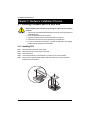
1
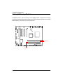
GA-5BXWL-RH
Xeon® 3000 Series Processor Motherboard
USER’S MANUAL
Intel® CoreTM2 Duo processor and Intel® CoreTM2 Quad processorMotherboard
Rev. 1001
*
The WEEE marking on the product indicates this product must not be disposed of with
user's other household waste and must be handed over to a designated collection point
for the recycling of waste electrical and electronic equipment!!
*
The WEEE marking applies only in European Union's member states.
English
GA-5BXWL-RH Motherboard
2
Introduction
Item Checklist
The GA-5BXWL-RH motherboard
IDE (ATA100 ) cable x 1 / Floppy cable x 1
Serial ATA cable x 4
I/O Shield Kit
CD for motherboard driver & utility
GA-5BXWL-RH Quick Reference Guide
SATA Power cable x 4
USB+1394 cable x 1
WARNING!
Computer motherboards and expansion cards contain very delicate Integrated Circuit (IC) chips. To
protect them against damage from static electricity, you should follow some precautions whenever you
work on your computer.
1.
2.
Unplug your computer when working on the inside.
Use a grounded wrist strap before handling computer components. If you do not have
one, touch both of your hands to a safely grounded object or to a metal object, such as
the power supply case.
3.
Hold components by the edges and try not touch the IC chips, leads or connectors, or
other components.
4.
Place components on a grounded antistatic pad or on the bag that came with the
components whenever the components are separated from the system.
5.
Ensure that the ATX power supply is switched off before you plug in or remove the ATX
power connector on the motherboard.
Installing the motherboard to the chassis…
If the motherboard has mounting holes, but they don’t line up with the holes on the base and there are
no slots to attach the spacers, do not become alarmed you can still attach the spacers to the mounting
holes. Just cut the bottom portion of the spacers (the spacer may be a little hard to cut off, so be careful
of your hands). In this way you can still attach the motherboard to the base without worrying about short
circuits. Sometimes you may need to use the plastic springs to isolate the screw from the motherboard
PCB surface, because the circuit wire may be near by the hole. Be careful, don’t let the screw contact
any printed circuit write or parts on the PCB that are near the fixing hole, otherwise it may damage the
board or cause board malfunctioning.
3
English
GA-5BXWL-RH Motherboard
Chapter 1 Introduction
1.1
Features Summary
Form Factor
y
12” x 9.6” ATX form factor, 6 layers PCB.
CPU
y
y
Supports single Intel® Xeon® processor
Intel® Dual Core/Quad Core in LGA 775 socket
Chipset
y
y
Supports 1066/1333MHz FSB
Intel® X38 MCH Chipset
Memory
y
y
Intel® 82801IR ICH9 RAID
4 x DDR2 DIMM sockets
y
y
Supports up to 8GB 667/800 memory
Dual Channel memory bus
y
y
Unbuffered DDR 667/800
ITE IT8718F-S Super I/O
y
y
Supports 4 PCI slots 32-Bit/33MHz
Supports 1 PCI-Express x16 slot
SATA RAID Controller
y
y
Supports 1 PCI-Express x4 slot
Built in Intel® 82801IR ICH9 RAID with Software RAID 0,1,10, 5
On-Board Graphic
y
y
Supports 5 SATA 3.0 Gb/s connectors
Build in Intel® X38 MCH Chipset
y
y
y
y
y
y
y
y
Relteak® ALC 262 Chipset
Support Jack-Sensing
Line Out / 2 front speaker
Line In / 2 rear speaker(by s/w switch)
Mic In / center& subwoofer(by s/w switch)
SPDIF Out /SPDIF In
CD_In
Surround Back speaker (by optional Surround-Kit)
y
y
Compliant with Vista Premium
TI TSB43AB23
y
2 x 1394a box headers
I/O Control
Expansion Slots
On-Board Sound
On-BoardIEEE 1934
4
Introduction
On-Board LAN
y
Broadcom® BCM5786 GbE controller
On-Board Peripherals
y
y
Supports WOL, PXE
1 x ATA 133 connector
y
y
1 x Floppy connector
2 x PS/2 connectors
y
y
1 x Parallel port supports Normal/EPP/ECP mode
1 x Serial port (COM)
y
y
2 x IEEE 1394 connectors
8 x USB 2.0 (4 x Rear, 4 x by cable)
y
y
4 x Audio ports (1 x Line-out/ 1 x Line-in/ 1 x MIC/ 1 by cable)
1 x LAN RJ45
y
y
5 x SATA 3.0Gb/s connectors
Enhanced features Voltage detection (+3.3V/+5V/+12V/Vbat/Vcore)
y
y
Temperature auto detection (CPU/VRM/chassis)
CPU shutdown when overheat
y
y
System Voltage Detect
AWARD BIOS on 8MB SPI ROM
y
y
y
PS/2 Mouse wake up from S1 under Windows Operating System
External Modem wake up
Supports S1, S4, S5 under Windows Operating System
y
y
Wake on LAN (WOL)
Wake on Ring (WOR)
y
y
AC Recovery
Supports Console Redirection
y
Supports 4-pin Fan controller
Hardware Monitor
BIOS
Additional Features
5
English
GA-5BXWL-RH Motherboard
1.2 GA-5BXWL-RH Motherboard Components
1.
CPU
24.
System fan cbale connector
2.
3.
Intel X38 MCH
Intel 82801IR ICH9 RAID
25.
26.
Channel 1DDR1 socket
Channel 2 DDR1 socket
4.
5.
ITE IT8718F-S
IEEE 1394 controller
27.
28.
Channel 2 DDR2 socket
Channel 2 DDR2 socket
6.
7.
Broadcom BCM5786
Realtek ALC262
29.
30.
PCI Express x4 slot
32bit/33MHz PCI slot #5
8.
9.
Case open intrusion connector
IDE Connector
31.
32.
32bit/33MHz PCI slot #4
32bit/33MHz PCI slot #3
10.
11.
Floppy Connector
SATA1 cable connector
33.
34.
32bit/33MHz PCI slot #2
PCI Express x16 slot
12.
13.
SATA2 cable connector
SATA3 cable connector
35.
36.
Keyboard Mouse port
COM port
14.
15.
SATA4 cable connector
SATA5 cable connector
37.
38.
Printer port
USB 2.0 port + IEEE1394
16.
17.
Internal Audio cable connector
Battery
39.
port
USB 2.0 port + Gigabit LAN
18.
19.
Internal USB cable connector
Front USB and IEEE 1394
40.
port
Audio port
20.
cable connectors
CPU fan cable connector
41.
42.
24-pin ATX power connector
4-pin ATX power connector
21.
Front fan cable connector
43.
Front panel connector
22.
23.
Rear fan cbale connector
Power supply fan cable connector
6
Introduction
37
8
7
5
16
29 30
31
32
40 39
22
33
36
38
35
6
34
42
18
1
2
19
4
20
25
3
26
27
13
11
15 14
12
17
28
21
41
10
43
23
24
7
9
English
GA-5BXWL-RH Motherboard
Chapter 2 Hardware Installation Process
2-1: Installing Processor and CPU Haet Sink
Before installing the processor and cooling fan, adhere to the following
cautions:
1. The processor will overheat without the heatsink and/or fan, resulting in permanent
irreparable damage.
2. Never force the processor into the socket.
3. Apply thermal grease on the processor before placing cooling fan.
4. Please make sure the CPU type is supported by the motherboard.
5. If you do not match the CPU socket Pin 1 and CPU cut edge well, it may damage
the CPU. Please change the insert orientation.
2-1-1: Installing CPU
Step 1 Raise the metal locking lever on the socket.
Step 2 Remove the plastic covering on the CPU socket.
Step 3 Lift the metal cover.
Step 4 Insert the CPU with the correct orientation. The CPU only fits in one orientation.
Step 5 Once the CPU is properly placed, please replace the metal cover and push the metal
lever back into locked position.
8
Hardware Installation Process
2-1-2: Installing Cooling Fan
Step 1 Attach the heat sink clip to the processor socket.
Step 2 Place the cooling fan on the heat sink.
Step 3 Secure the cooing fan with screws.
Step 4 Connect processor fan can cable to the processor fanconnector
9
English
GA-5BXWL-RH Motherboard
2-2: Install Memory Modules
GA-5BXWL-RH has 4 dual inline memory module (DIMM) sokcets. It supports Dual Channels
Technology. The BIOS will automatically detects memory type and size during system boot. For detail
DIMM installation, please refer to the following instructions.
Channel 1
Channel 2
10
Hardware Installation Process
Table 1. Supported DIMM Module Type
Size
256MB
512MB
1GB
Organization
8MB x 8 x 4 bks
16MB x 4 x 4bks
16MB x 8 x 4bks
32MB x 4 x 4bks
32MB x 8 x 4bks
64MB x 4 x 4bks
RAM Chips/DIMM
8
16
8
16
8
16
Installation Steps:
1. Unlock a DIMM socket by pressing the retaining clips outwards.Aling a DIMM on the socket such
that the notch on the DIMM exactly match the notch in the socket.
2. Firmly insert the DIMMinto the socket until the retaining clips snap back in place.
NOTE!! We recommened you to populate the same device size on each socket and the
same DIMM size.
4. Reverse the installation steps if you want to remove the DIMM module.
11
English
GA-5BXWL-RH Motherboard
2-3: Connect ribbon cables, cabinet wires, and power
supply
2-3-1 : I/O Back Panel Introduction
12
Hardware Installation Process
PS/2 Keyboard and PS/2 Mouse Connector
To install a PS/2 port keyboard and mouse, plug the mouse to the upper port (green) and the keyboard
to the lower port (purple).
Parallel Port
The parallel port allows connection of a printer, scanner and other peripheral devices.
COM Port
Modem can be connected to COM port.
IEEE1394 Port
Serial interface standard set by Institute of Electrical and Electronics Engineers, which has
features with high speed, high bandwidth and hot plug
USB Port
Before you connect your device(s) into USB connector(s), please make sure your device(s)
such as USB keyboard, mouse, scanner, zip, speaker...etc. have a standard USB interface.
Also make sure your OS supports USB controller. If your OS does not support USB controller,
please contact OS vendor for possible patch or driver updated. For more information please
contact your OS or device(s) vendors.
LAN Port
The provided Internet connection is Gigabit Ethernet, providing data transfer speeds of 10/100/
1000Mbps.
Line In
The default Line In jack. Devices like CD-ROM, walkman etc. can be connected to Line In jack.
Line Out (Front Speaker Out)
The default Line Out (Front Speaker Out) jack. Stereo speakers, earphone or front surround
speakers can be connected to Line Out (Front Speaker Out) jack.
MIC In
The default MIC In jack. Microphone must be connected to MIC In jack.
13
English
GA-5BXWL-RH Motherboard
2-4: Connectors Introduction & Jumper Setting
17
10
2
11
12
15
20
21
22
14
9
7
5
8
6
16
3
13
1
18
19
13. F_PANEL1
14. BAT1 (Battery)
1. ATX1
2. ATX_12V
3. IDE1 (IDE cable connector)
15. CPU_FAN
4. FDD (Floppy cable connector)
5. S_ATA1 (SATA cable connector)
16. FRONT_FAN
17. REAR_FAN
6. S_ATA2 (SATA cable connector)
7. S_ATA3 (SATA cable connector)
18. PSU_FAN
19. SYS_FAN
8. S_ATA4 (SATA cable connector)
9. S_ATA5 (SATA cable connector)
20. JP2
21 JP3
10. FAUDIO_ACZ
11. F_USB2 (Internal USB cable connector)
22.. JP1
12. F_USB1+1394 (Front 1394 cable connector)
14
4
Connector Introduction
1) ATX1 (Auxuliary Power Connector)
AC power cord should only be connected to your power supply unit after ATX power cable and
other related devices are firmly connected to the mainboard.
1
13
12
24
PIN No.
Definition
1
+3.3V
2
3
+3.3V
GND
4
5
+5V
GND
6
7
+5V
GND
8
9
POK
5VSB
10
11
+12V
+12V
12
13
+3.3V
+3.3V
14
15
-12V
GND
16
17
PSON
GND
18
19
GND
GND
20
21
-5V
+5V
22
23
+5V
+5V
24
GND
2 ) ATX2 (Auxuliary +12V Power Connector)
4
2
3 1
Pin No.
1
Definition
GND
2
3
GND
+12V
4
+12V
This connector (ATX +12V) is used only for
CPU Core Voltage.
15
English
GA-5BXWL-RH Motherboard
3 ) IDE (IDE Connector)
Please connect first harddisk to IDE1. The red stripe of the ribbon cable must be the same side with
the Pin1.
2
40
1
39
4 ) FDD (Floppy Connector)
Please connect the floppy drive ribbon cables to FDD. It supports 720K,1.2M,1.44M and
2.88Mbytes floppy disk types. The red stripe of the ribbon cable must be the same side with the
Pin1.
2
1
16
34
33
Connector Introduction
5/ 6/ 7/ 8/ 9 ) S_ATA 1~5 (Serial ATA cable connectors)
You can connect the Serial ATA device to this connector, it provides you high speed transfer rates
(3.0Gb/s).
1
Pin No.
1
2
3
4
5
6
7
7
Definition
GND
TXP
TXN
GND
RXN
RXP
GND
S_ATA3
S_ATA1
S_ATA4 S_ATA2
S_ATA5
10) FAUDIO_ACZ (Front AUDIO cable connector)
If you want to use Front Audio connector, you must remove 5-6, 9-10 Jumper. In order to utilize the
front audio header, your chassis must have front audio connector. Also please make sure the pin
assigment on the cable is the same as the pin assigment on the MB header. To find out if the chassis
you are buying support front audio connector, please contact your dealer.
1 2
9 10
17
Pin No.
Definition
1
MIC_L
2
GND
3
MIC_RI
4
DETECT
5
FrontAudio(R)
6
RearAudio(R)
7
Reserved
8
No Pin
9
FrontAudio (L)
10
RearAudio(L)
English
GA-5BXWL-RH Motherboard
11 ) F_USB2 (Internal USB cable connector)
Be careful with the polarity of the front USB connector. Check the pin assignment carefully while
you connect the front USB cable, incorrect connection between the cable and connector will make
the device unable to work or even damage it. For optional front USB cable, please contact your
local dealer.
1 2
11 12
Pin No.
1
Definition
No Pin
2
3
Power
Power
4
5
Power
-USB6
6
7
-USB7
+USB6
8
9
+USB7
GND
10
11
GND
No Pin
12
NC
12 ) F_USB1+1394 (Front USB and IEEE 1394 cable connectors)
1 2
19 20
18
Pin No.
1
2
3
4
5
6
7
8
9
10
11
12
13
14
15
16
17
18
19
20
Definition
Power
Power
-USB4
-USB5
+USB4
+USB5
GND
GND
NC
NC
Power
Power
TPA1+
TPA1GND
GND
TPB1+
TPB1No Pin
NC
Connector Introduction
13 ) F_Panel (2X10 Pins Front Panel connector)
Please connect the power LED, PC speaker, reset switch and power switch of your chassis
front panel to the F_PANEL connector according to the pin assignment above.
NOTE!! Please note that the onborad front panel connector must attach with
adapt cable to enable front panel function.
2
1
Pin No
Signal Name
Description
1
2
HDD+
No Pin
Pin removed
3
4
HDDNo Pin
Pin removed
5
6
RESETPW+
Reset button cathode(-)
Power button switch anode (+)
7
8
RESET+
PW-
Reset button anode (+)
Power button switch cathode(-)
9
10
No Pin
No Pin
Pin removed
11
12
No Pin
No Pin
Pin removed
13
14
No Pin
No Pin
Pin removed
15
16
MPD+
No Pin
Pin removed
17
18
MPDNo Pin
Pin removed
19
20
SLEEP LED
No Pin
Hard Disk LED anode (+)
Hard Disk LED cathode(-)
Pin removed
Pin removed
Pin removed
Message LED/Power LED anode (+)
Message LED/Powe LED cathode(-)
Sleep LED
Pin removed
19
20
19
English
GA-5BXWL-RH Motherboard
14 ) BAT1 (Battery)
CAUTION
Danger of explosion if battery is incorrectly
replaced.
Replace only with the same or equivalent
type recommended by the manufacturer.
Dispose of used batteries according to the
manufacturer’s instructions.
If you want to erase CMOS...
1.Turn OFF the computer and unplug the power cord.
2.Remove the battery, wait for 30 second.
3.Re-install the battery.
4.Plug the power cord and turn ON the computer.
15 ) CPU_FAN (CPU fan cable connector)
Please note, a proper installation of the CPU cooler is essential to prevent the CPU from running
under abnormal condition or damaged by overheating.The CPU fan connector supports Max. current
up to 1A .
1
20
Pin No.
1
2
3
4
Definition
GND
12V
Sense
Control
Connector Introduction
16/17 ) FRONT_FAN/REAR_FAN (Front Fan and Rear fan cable connectors)
This connector allows you to link with the cooling fan on the system case to lower the system
temperature. These connectors are for system use only.
REAR_FAN
Pin No.
1
2
3
4
1
Definition
GND
12V
Sense
Control
FRONT_FAN
18 ) PSU_FAN (Power supply fan cable connector)
This connector allows you to link with the cooling fan on the system case to lower the system
temperature.
1
21
Pin No.
1
2
3
Definition
GND
+12V
Sense
English
GA-5BXWL-RH Motherboard
19 ) SYS_FAN (System Fan Connector)
This connector allows you to link with the cooling fan on the system case to lower the system
temperature. These connectors are for system use only.
1
22
Pin No.
1
2
3
Definition
GND
+12V
Sense
Connector Introduction
20 ) JP2 (Skip password jumper)
1
1-2 Close: Normal operation (Default setting)
1
2-3 Close: Skip Supervisor Password in
21 ) JP3 (BIOS recovery jumper)
1
1
1-2 Close: Normal operation (Default setting)
2-3 Close: Enable BIOS Recovery mode
23
English
GA-5BXWL-RH Motherboard
22 ) JP1 (Clear CMOS jumper)
You may clear the CMOS data to restore its default values by this jumper.
Default value doesn’t include the “Shunter” to prevent from improper use this jumper. To
clear CMOS, temporarily short 1-2 pin.
1
1
1-2 Close: Normal operation (Default setting)
2-3 Close: Clear CMOS
24
Block Diagram
2-5: Block Diagram
INTEL LGA775
Xeon
CLOCK GENERATOR
CK505
VID0~5
VRD 11
Wolfdale/Concore/
Kentsfield/YorkfieldFSB
1333/1066/800
FSB
PCI-E Graphic Card
CHANNEL A
DDR2 667/800 Un-Buffered
ECC/ Non ECC DIMM x 2
PCIE x16
PCIE x16 Slot
MCH
BEARLAKE-X
Intel X38
DMI_PN_0~3
Control Bus
CHANNEL B
DDR2 667/800 Un-Buffered
ECC/ Non ECC DIMM x 2
DMI
PCI
IEEEE 1394a
TSB43AB23
1394
1394
USB
USB
SATA x 5
USB
Intel
82801IR ICH9 RAID
Front Panel
1394
PCI 32/33MHz Slot
PCI 32/33MHz Slot
PCIE x4
SPI
FWH
Rear Panel
RJ45
&
USBx2
PCI-E x 4 Slot
USB
TPM 1.2
LPC BUS
PCIE x1
PCI 32/33MHz Slot
Broadcom
BCM5786/GbE
USB
SPI BUS
PCI 32/33MHz Slot
PCIE x1
USB x 2
USB x 2
ITE 8718F
JMB-368
Audio
ALC262
IDE
IDE Connector
Audio
Phone
Jack
Front Audio Port
CD_IN
COM1
KB
&
MS
Floppy Connector
25
Printer Port
BIOS Setup
Chapter 5 BIOS Setup
BIOS Setup is an overview of the BIOS Setup Program. The program that allows users to modify the
basic system configuration. This type of information is stored in battery-backed CMOS RAM so that it
retains the Setup information when the power is turned off.
ENTERINGSETUP
Power ON the computer and press <F2> immediately will allow you to enter Setup.
CONTROLKEYS
<Ç>
Move to previous item
<È>
Move to next item
<Å>
Move to the item in the left hand
<Æ>
Move to the item in the right hand
<Esc>
Exit current page and return to Main Menu
<+/PgUp> Increase the numeric value or make changes
<-/PgDn>
Decrease the numeric value or make changes
<F1>
General help, only for Status Page Setup Menu and Option Page Setup Menu
<F2>
Reserved
<F3>
Reserved
<F4>
Reserved
<F5>
Restore the previous CMOS value from CMOS, only for Option Page Setup Menu
<F6>
Reserved
<F7>
Load the Optimized Defaults
<F8>
Reserved
<F9>
Reserved
<F10>
Save all the CMOS changes
27
GA-5BXWL-RH Motherboard
GETTINGHELP
Main Menu
The on-line description of the highlighted setup function is displayed at the bottom of the screen.
Status Page Setup Menu / Option Page Setup Menu
Press F1 to pop up a small help window that describes the appropriate keys to use and the possible
selections for the highlighted item. To exit the Help Window press <Esc>.
z
Info
Display BIOS veriosn, CPU Type and Speed, and total memory populated
z
Sytem
This setup page includes all the items in standard compatible BIOS.
z
Advanced
This setup page includes all the items of AWARD special enhanced features.
(ex: onboard device enable/disable, power management)
z
Security
Change, set, or disable password. It allows you to limit access to the system and Setup,
or just to Setup.
z
PC Health
This setup page displays the System auto detect Temperature, voltage, fan speed.
z
Exit
Save CMOS value settings to CMOS and exit setup or abandon all CMOS value changes
and exit setup.
28
GA-5BXWL-RH Motherboard
Info
Once you enter Award BIOS Setup Utility, the Main Menu (Figure 1) will appear on the screen. Use
arrow keys to select among the items and press <Enter> to accept or enter the sub-menu.
Phoenix - AwardBIOS CMOS Setup Utility
Info
Sysetm
Advanced
Seccurity
Product Name
GA-5BXWL-RH
Serial Number
F1
BIOS Version
F1
BIOS Date
01/30/2008
Processor Type
IntelCPU
Processor Speed
2.33GHz/1332MHz
L1 Cache
32KB
L2 Cache
6144KB
Total Memory
511MB
DIMM1
512MB/667MHz
DIMM2
Not Installed
DIMM3
Not Installed
DIMM4
Not Installed
Memory Channel
Single
Onboard LAN Mac Adress
00:00:00:00:00:00
UUID
0000000000000000
PC Health
Exit
Item Help
0000000000000000
Configuration ID
K L J I : Move
0000000000000000
Enter: Select +/-/PU/PD: Value
F5: Previous Values
F10: Save
F7: Setup Defaults
Figure 1: Info
29
ESC: Exit
F1: General Help
GA-5BXWL-RH Motherboard
System
Phoenix - AwardBIOS CMOS Setup Utility
Info
Sysetm
Advanced
Seccurity
PC Health
Date (mm:dd:yy)
2007/Feb/1 Thu
Time (hh:mm:ss)
15:1:47
IDE Channel 0 Master
[None]
IDE Channel 0 Slave
[None]
IDE Channel 1 Master
[None]
IDE Channel 1 Slave
[None]
IDE Channel 2 Master
[None]
Drive A
K L J I : Move
Exit
Item Help
[1.44M, 3.5 1/2 ]
Enter: Select +/-/PU/PD: Value
F5: Previous Values
F10: Save
ESC: Exit
F1: General Help
F7: Setup Defaults
Figure 2: System
& Date
The date format is <year> <month>, <day>.
Date
The date, Monday to Sunday.
Month
The month, Jan. Through Dec.
Day
The day, from 1 to 31 (or the maximum allowed in the month)
Year
The year, from 1999 through 2098
& Time
The times format is set in <hour>, <minute> and <second>. The time is calculated base on the 24hour military-time clock. For example, 1 p.m. is 13:00:00.
30
GA-5BXWL-RH Motherboard
& IDE Channel 0 Master, Slave / Channel 1 Master, Slave /Channel 2
Master / Channel 4 Master
The category identifies the types of hard disk from drive C to F that has been installed in the
computer. There are two types: auto type, and manual type. Manual type is user-definable; Auto
type that will automatically detect HDD type.
Note that the specifications of your drive must match with the drive table. The hard disk will not work
properly if you enter improper information for this category.
If you select User Type, related information will be asked to enter to the following items. Enter the
information directly from the keyboard and press <Enter>. Such information should be provided in the
documentation form your hard disk vendor or the system manufacturer.
& IDE HDDAuto Detection
Press [Enter] to auto-detect the HDD’s size, head, etc on this channel.
& Access Mode
This option allows user to set hard drive parameters.
Option: CHS, LBA, Large, Auto (Default Value)
Capacity
Displays the capacity of HDD
Cylinder
Number of cylinders
Heads
Number of heads
Precmp
Write precomp
Landind Zone
Landing zone
Sectors
Number of sectors
31
GA-5BXWL-RH Motherboard
& Drive A
The category identifies the types of floppy disk drive A that has been installed in the computer.
No floppy drive installed
None
360K, 5 in.
5.25 inch PC-type standard drive; 360K byte capacity.
1.2M, 51/4 in.
5.25 inch AT-type high-density drive; 1.2M byte capacity
1/4
(3.5 inch when 3 Mode is Enabled).
720K, 3 in.
3.5 inch double-sided drive; 720K byte capacity
1.44M, 3
in.
3.5 inch double-sided drive; 1.44M byte capacity.
2.88M, 3 1/2 in.
3.5 inch double-sided drive; 2.88M byte capacity.
1/2
1/2
32
GA-5BXWL-RH Motherboard
Advanced
Phoenix - AwardBIOS CMOS Setup Utility
Info
Sysetm
Advanced
Seccurity
PC Health
Advanced BIOS Feature
Exit
Item Help
Integrated Peripherals
Power Management Setup
K L J I : Move
Enter: Select +/-/PU/PD: Value
F5: Previous Values
F10: Save
F7: Setup Defaults
Figure 3: Advanced
33
ESC: Exit
F1: General Help
BIOS Setup
Advanced BIOS Feature
Phoenix - AwardBIOS CMOS Setup Utility
Advanced
Advanced BIOS Feature
Item Help
Hard Disk Boot Priority
Quick Power On Self Test
[Enabled]
Full Screen LOGO Show
[Enabled]
First Boot Device
[USB-FDD]
Second Boot Device
[Hard Disk]
Third Boot Device
[CD/DVD]
Boot Menu
[Enabled]
Boot Up Flppy Seek
[Enabled]
Boot Num-Lock
[On]
Init Display First
[PEG]
Limit CPUID Max to 3
[Disabled]
Execute Disable Bit
[Enabled]
CPU EIST Function
[Enabled]
Virtualizational Technology
[Disabled]
Core Multi-Processing
[Enabled]
K L J I : Move
Enter: Select +/-/PU/PD: Value
F5: Previous Values
F10: Save
ESC: Exit
F7: Setup Defaults
Figure 3-1: Advanced BIOS Features
34
F1: General Help
GA-5BXWL-RH Motherboard
&Hard DiskBoot Priority
Press [Enter] to set the hard disk boot priority.
&Quick Power On Self Test
This category speeds up Power On Self Test (POST) after you power on the computer. If it is set
to Enable, BIOS will shorten or skip some check items during POST.
Enabled
Enables quick POST.(Default setting)
Disabled
Normal POST.
&Full Screen LOGO Show
Enabled
Enables Full LOGO show when system boot.(Default setting)
Disabled
Disable Full LOGO show when system boot.
& First / Second/ Third Boot Device
Select the first/second/t\hird boot device
Floppy
Select your boot device priority by Floppy.
Hard Disk
Select your boot device priority by Hard Disk.
CD/DVD
Select your boot device priority by CD/DVD.
USB-FDD
Select your boot device priority by USB-FDD.
USB-CDROM
Select your boot device priority by USB-CDROM.
LAN
Select your boot device priority by LAN.
Disabled
Select your boot device priority by Disabled.
& Boot Menu
Select the specified boot device priority.
Enabled
Enable the specified boot device. (Default setting)
Disabled
Disable the specified boot device.
&Boot Up Floppy Seek
During POST, BIOS will determine the floppy disk drive installed is 40 or 80 tracks. 360K type is
40 tracks 720K, 1.2M and 1.44M are all 80 tracks.
35
BIOS Setup
Enabled
BIOS searches for floppy disk drive to determine it is 40 or 80 tracks. Note
that BIOS can not tell from 720K, 1.2M or 1.44M drive type as they are all
80 tracks. (Default setting)
Disabled
BIOS will not search for the type of floppy disk drive by track number. Note
that there will not be any warning message if the drive installed is 360K.
& Boot Up Num-Lock
On
Enable the Boot Up Num-Lock. (Default setting)
Off
Disable this function.
&Init Display First
This feature allows you to select the first initation of the monitor display from which card, when
you install an AGP VGA card and a PCI VGA card on board.
PEG
Set Init Display First to PCI Express Slot. (Default setting)
PCI Slot
Set Init Display First to PCI Slot.
&Limit CPU ID Max to 3
Enabled
Set Limit CPU ID Max value to be 3.
Disabled
Disables this function. (Default setting)
&Execute Diable Bit
Execute Disable Bit allows the processor to classify areas in memory by where application code
can execute and where it cannot. When a malicious worm attempts to insert code in the buffer, the
processor disables code execution, preventing damage and worm propagation.
Enabled
Enable Execute Disable Bit. (Default setting)
Disabled
Disable this function.
&CPU EIST Function
Enabled
EIST function Driver manages clock and VID to be serve the thermal,
performance and power requirement. (Default setting)
36
BIOS Setup
Disabled
Disables this function.
&Virtualization Technology
Intel(R) Virtualization Technology will allow a platform to run multiple operating systems and
applications in independent partitions. With virtualization, one computer system can function as
multiple “virtual” systems. With processor and I/O enhancements to Intel’s various platforms,
Intel Virtualization Technology can improve the performance and robustness of today’s softwareonly virtual machine solutions.
Enabled
Enable Intel Virtualization Technology.
Disabled
Disable this function. (Default setting)
&Core Multi-Processing
Determines whether the 2nd core is enabled.
Enabled
Enable 2nd core. (Default setting)
Disabled
Disables P2nd core.
37
GA-5BXWL-RH Motherboard
Integrated Peripherals
Phoenix - AwardBIOS CMOS Setup Utility
Advanced
Integrated Peripherals
Item Help
SATA Mode
[IDE]
LEGACY Mode Support
[Enabled]
PATA Controller
[Enlabled]
Audio Controller
[Enabled]
Onboard H/W 1394
[Enabled]
Onboard H/W LAN
[Enabled]
Onboard LAN Boot ROM
[Enabled]
Onboard Serial port 1
[3F8/IRQ4]
Onb oard Parallel port
[378/IRQ7]
Parallel Port Mode
[ECP]
ECP Mode Use DMA
[3]
USB Controller
[Enabled/All]
USB 2.0 Controller
[Enabled]
USB Keyboard Support
[Disabled]
USB Mouse Support
[Disabled]
USB Storage Support
[Enabled]
****** USB Mass Storage Device Boot Setting ******
K L J I : Move
Enter: Select +/-/PU/PD: Value
F5: Previous Values
F10: Save
F7: Setup Defaults
Figure 3-2: Integrated Peripherals
38
ESC: Exit
F1: General Help
BIOS Setup
&SATA Mode
IDE
Disable both RAID/AHCI function. (Defualt setting)
AHCI
Enable SATA as AHCI function.
RAID
Enable SATA as RAID function.
&LEGACY Mode Support
Enabled
Enable LEGACY Mode Support. (Default setting)
Disabled
Disable LEGACY Mode Support function.
&PATA Controller
Enabled
Enable onabord PATA controller. (Default setting)
Disabled
Disable onabord PATA controller.
&Audio Controller
Enabled
Enable onabord audio controller. (Default setting)
Disabled
Disable onabord audio controller.
&Onboard H/W 1394
Enabled
Enable onboard H/W 1394. (Default setting)
Disabled
Disableonboard H/W 1394.
&Onboard H/W LAN
Enabled
Enable onboard LAN controller. (Default setting)
Disabled
Disable onboard LAN controller.
&Onboard LAN Boot ROM
Enabled
Enable onboard LAN boot ROM. (Default setting)
Disabled
Disable onboard LAN boot ROM.
39
GA-5BXWL-RH Motherboard
&Onboard Serial Port 1
3F8/IRQ4
Enable onboard Serial port 1 and set IO address to 3F8. (Default setting)
2F8/IRQ3
Enable onboard Serial port 1 and set IO address to 2F8.
3E8/IRQ4
Enable onboard Serial port 1 and set IO address to 3E8.
2E8/IRQ3
Enable onboard Serial port 1 and set IO address to 2E8.
Disabled
Disable onboard Serial port 1.
&Onboard Parallel Port
378/IRQ7
Enable onboard LPT port and set address to 378/IRQ7. (Default setting)
278/IRQ5
Enable onboard LPT port and set address to 278/IRQ5.
3BC/IRQ7
Enable onboard LPT port and set address to 3BC/IRQ7.
Disabled
Disable onboard LPT port.
&Parallel Port Mode
SPP
Using Parallel port as Standard Parallel Port.
EPP
Using Parallel port as Enhanced Parallel Port.
ECP
Using Parallel port as Extended Capabilities Port. (Default setting)
ECP+EPP
Using Parallel port as ECP & EPP mode.
&ECP Mode Use DMA
This option is only available if the setting for the Parallel Port Mode option is ECP. This option
sets the DMA channel used by parallel port.
The options: 1,3. Default setting is 3.
&USB Controller
Enabled/All
Enable all USB controllers. (Default setting)
Rear Only
Enable rear USB controller only.
Disabled
Disable all USB controller.
40
BIOS Setup
&USB 2.0 Controller
This item provide the function for user to enable/disable EHCI controller only. THis BIOS
itself may / may not have high speed USB support built-in, the support will be
automatically turn on when high speed device were attached.
Enabled
Enable USB 2.0 Controller function. (Default setting)
Disabled
Disable USB 2.0 Controller function.
&USB Keyboard Support
Enabled
Enable USB Keyboard support. (Default setting)
Disabled
Disable USB Keyboard support.
&USB Mouse Support
Enabled
Enable USB Mouse Support. (Default setting)
Disabled
Disable USB Mouse Support.
&USB Storage Support
Enabled
Enable legacy support of USB mass storage. (Default setting)
Disabled
Disable egacy support of USB mass storage.
41
GA-5BXWL-RH Motherboard
Power Management Setup
Phoenix - AwardBIOS CMOS Setup Utility
Advanced
Power Management
Item Help
AC Back Function
[Disabled]
PME Event Wake Up
[Disabled]
Resume By Alarm
[Disabled]
x Date (of Month) Alarm
0
x Time (hh: mm: ss)
K L J I : Move
0:0:0
Enter: Select +/-/PU/PD: Value
F5: Previous Values
F10: Save
ESC: Exit
F1: General Help
F7: Setup Defaults
Figure 3-3: Power Management Setup
& AC Back Function
Soft-Off
When AC-power back to the system, the system will be in "Off" state.
Full-On
When AC-power back to the system, the system always in "On" state.
Memory
When AC-power back to the system, the system will return to the Last state
before AC-power off.
Disabled
Disable this function. (Default setting)
& PME Event Wake Up
Enabled
Enable PME Event Wake Up function.
Disabled
Dsiable PME Event Wake Up function.
42
BIOS Setup
& Resume by Alarm
You can set "Resume by Alarm" item to enabled and key in Data/time to power on system.
Disabled
Disable this function. (Default setting)
Enabled
Enable alarm function to POWER ON system.
If RTC Alarm Lead To Power On is Enabled.
Date ( of Month) Alarm :
Everyday, 1~31
Time ( hh: mm: ss) Alarm :
(0~23) : (0~59) : (0~59)
43
BIOS Setup
Security
Phoenix - AwardBIOS CMOS Setup Utility
Info
Sysetm
Advanced
Seccurity
PC Health
Set Supervisor Password
Exit
Item Help
x Set User Password
Password Check
[Setup]
Halt On
[All Errors]
Chassis Opening Warning
[Disabled]
x Hard Disk Security
x Security Chip Configuration
KLJI : Move
Enter: Select +/-/PU/PD: Value
F5: Previous Values
F10: Save
ESC: Exit
F1: General Help
F7: Setup Defaults
Figure 4: Security
When you select this function, the following message will appear at the center of the screen to
assist you in creating a password.
Type the password, up to eight characters, and press <Enter>. You will be asked to confirm the
entered password. Type the password again and press <Enter>. You may also press <Esc> to
abort the selection and not enter a password.
To disable password, just press <Enter> when you are prompted to enter password. A
message “PASSWORD DISABLED” will appear to confirm the password being disabled. Once the
password is disabled, the system will boot and you can enter Setup freely.
The BIOS Setup program allows you to specify two separate passwords:
SUPERVISOR PASSWORD and a USER PASSWORD. When disabled, anyone may access all
BIOS Setup program function. When enabled, the Supervisor password is required for entering the
BIOS Setup program and having full configuration fields, the User password is required to access
only basic items.
If you select “System” at “Password Check” in Advance BIOS Features Menu, you will be
prompted for the password every time the system is rebooted or any time you try to enter Setup
Menu.
If you select “Setup” at “Password Check” in Advance BIOS Features Menu, you will be
prompted only when you try to enter Setup.
44
GA-5BXWL-RH Motherboard
& Password Check
Select whether the password is required every time when the system boots or only when user
enter the setup.
& Halt On
The category determines whether the computer will stop if an error is detected during power up.
NO Errors
The system boot will not stop for any error that may be detected
and you will be prompted.
All Errors
Whenever the BIOS detects a non-fatal error the system will be
stopped. (Default setting)
All, But Keyboard
The system boot will not stop for a keyboard error; it will stop for
all other errors.
All, But Diskette
The system boot will not stop for a disk error; it will stop for all
other errors.
All, But Disk/Key
The system boot will not stop for a keyboard or disk error; it will
stop for all other errors.
& Chassis Opening Warning
Set this option to Enabled to active warning beep sound when the system chassis is opened.
Enabled
Enable chassis opening warning.
Disabled
Disable this function. (Default setting)
45
BIOS Setup
PC Health
Phoenix - AwardBIOS CMOS Setup Utility
Info
Sysetm
Advanced
Seccurity
PC Health
DMI Event Log
Exit
Item Help
Temperature
Voltage
FAN
KLJI : Move
Enter: Select +/-/PU/PD: Value
F5: Previous Values
F10: Save
ESC: Exit
F1: General Help
F7: Setup Defaults
Figure 5: PC Health
& DMI Event Log
Press [Enter] to view the event logging information.
& Temperature
Display the current CPU and PECI temperature, motherboard front and rear temperature.
& Voltage: VCORE/ +5V/ +3.3V/ +12V/ VBAT
Detect system's voltage status automatically.
& FAN (RPM)
Display the current CPU, Front, Rear, System and Power FAN speed.
46
BIOS Setup
Exit
Phoenix - AwardBIOS CMOS Setup Utility
Sysetm
Advanced
Seccurity
PC Health
Save & Exit Setup
Exit
Item Help
Save & Turn Off
Exit Without Saving
Load Setup Defaults
KLJI : Move
Enter: Select +/-/PU/PD: Value
F5: Previous Values
F10: Save
ESC: Exit
F1: General Help
F7: Setup Defaults
Figure 6: Exit
&Save & Exit Setup
Type “Y” will quit the Setup Utility and save the user setup value to RTC CMOS.
Type “N” will return to Setup Utility.
&Save & Turn Off
Type “Y” will quit the Setup Utility and save the user setup value to RTC CMOS and turn of
power automatically.
Type “N” will return to Setup Utility.
&Exit Without Saving
Type “Y” will abandon all data and quit without saving.
Type “N” will return to Setup Utility.
&Load Setup Defaults
Selecting this field loads the factory defaults for BIOS and Chipset Features which the
system automatically detects.
47