1
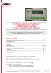
600-E Series Digital Baggage Scales Installation / Setup / Operation Manual Revision 2.1 February 18, 2003 2003 Triner Scale & Mfg. Co., Inc. Contents subject to change without notice. Triner Scale 8411 Hacks Cross Road Olive Branch, MS 38654 Tel (800) 238-0152 E-mail: [email protected] Web: www.trinerscale.com TABLE OF CONTENTS Page Chapter 1: Introduction To The 600E Digital Baggage Scale ........................................................ 1-1 Chapter 2: Installation ................................................................................................................... 2-1 2.1 Parts List...................................................................................................................... 2-1 2.2 Scale Base Installation (Standard Style)...................................................................... 2-1 2.3 Scale Base Installation (Full Well Style) ...................................................................... 2-3 2.4 Scale Base Installation (Low Profile Style) .................................................................. 2-4 2.5 Digital Display and Keypad Installation........................................................................ 2-5 2.6 Load Cell Connections................................................................................................. 2-9 2.7 Connecting Serial Printer, Remote Display or Computer............................................. 2-9 2.8 Connecting the Power Supply ..................................................................................... 2-9 Chapter 3: Configuration ............................................................................................................... 3-1 3.1 Configuration Overview ............................................................................................... 3-1 3.2 Setup (“F”) Menu ......................................................................................................... 3-1 3.3 Chapter 4: 4.1 Chapter 5: 3.2.1 Entering the Setup Menu ................................................................................ 3-1 3.2.2 Navigating in the Setup Menu......................................................................... 3-1 3.2.3 Notes on the Setup Menu ............................................................................... 3-2 3.2.4 Exiting the Setup Menu................................................................................... 3-2 User (“A”) Menu ........................................................................................................... 3-3 3.3.1 Entering the User Menu .................................................................................. 3-3 3.3.2 Navigating in the User Menu........................................................................... 3-3 3.3.3 Notes on the User Menu ................................................................................. 3-4 3.3.4 Exiting the User Menu..................................................................................... 3-4 Setup Menu Descriptions and Procedures .................................................................. 4-1 Setup Menu Descriptions............................................................................................. 4-1 User Menu Descriptions and Procedures .................................................................... 5-1 5.1 User Menu Descriptions .............................................................................................. 5-1 5.2 User Menu Procedures................................................................................................ 5-2 Chapter 6: 5.2.1 ID Number Entry (A8) ..................................................................................... 5-2 5.2.2 Line Feeds Entry (A9) ..................................................................................... 5-2 Calibration ................................................................................................................... 6-1 6.1 Calibration Overview.................................................................................................... 6-1 6.2 Zero Calibration (F16).................................................................................................. 6-1 6.3 Span Calibration (F17)................................................................................................. 6-1 i 6.4 View Calibration Values (F18) ..................................................................................... 6-2 6.5 Key-in Zero Calibration Value (F19) ............................................................................ 6-2 6.6 Key-in Span Calibration Value (F20) ........................................................................... 6-3 Chapter 7: 7.1 Operation..................................................................................................................... 7-1 Display......................................................................................................................... 7-1 7.1.1 7.2 Remote Keyboard........................................................................................................ 7-1 7.2.1 7.3 Light Emitting Diode (LED) Display................................................................. 7-1 Function Keys ................................................................................................. 7-2 General Scale Operation ............................................................................................. 7-2 7.3.1 Weighing an item ............................................................................................ 7-2 7.3.2 Accumulation Function.................................................................................... 7-2 Appendix A: Specifications............................................................................................................... A-1 Appendix B: Serial Port Information ................................................................................................. B-1 B.1 Serial Port Modes ........................................................................................................ B-1 B.1.1 Full Duplex Mode............................................................................................ B-1 B.1.1.1 Recognized Host Commands ......................................................... B-2 B.1.2 Print Ticket Mode............................................................................................ B-2 B.1.3 Simplex Mode ................................................................................................. B-3 Appendix C: Determining Proper Span Gain (F2) ............................................................................ C-1 C.1 Span Gain Overview.................................................................................................... C-1 C.2 Setting the initial value for span gain ........................................................................... C-1 C.3 Viewing the internal counts.......................................................................................... C-1 Appendix D: Displayed Error Codes................................................................................................. D-1 ii LIST OF FIGURES 1-1 1-2 1-3 2-1 2-2 2-3 2-4 2-5 2-6 2-7 2-8 Standard Style....................................................................................................................... Full Well Style........................................................................................................................ Low Profile Style.................................................................................................................... Bottom Of Scale (Shipping Screw) ........................................................................................ Corner Detail ......................................................................................................................... System Block Diagram .......................................................................................................... Bottom Of Scale (Shipping Screw) ........................................................................................ Corner Detail ......................................................................................................................... Corner Detail ......................................................................................................................... Display Cut Out Detail ........................................................................................................... Display Cable Detail .............................................................................................................. 1-1 1-2 1-3 2-1 2-2 2-2 2-3 2-3 2-4 2-5 2-6 2-9 2-10 2-11 2-12 2-13 2-14 3-1 3-2 3-3 5-1 6-1 7-1 7-2 B-1 B-2 B-3 B-4 B-5 Keypad Cut Out Detail........................................................................................................... Keypad Cable Detail.............................................................................................................. Color Codes for Shielded Load Cell Cable............................................................................ Pin Assignments for the Load Cell Port................................................................................. Pin Assignments for the Summing Card................................................................................ Pin Assignments for the DSUB9 serial port connector .......................................................... Setup Menu Key Assignments .............................................................................................. Setup Menu Chart ................................................................................................................. User Menu Chart ................................................................................................................... User Menu Key Assignments ................................................................................................ Setup Menu Key Assignments .............................................................................................. 600E LED Display Detail ....................................................................................................... Function Keys Layout............................................................................................................ Cable Diagram for Indicator to IBM PC ................................................................................. Consolidated Controls Demand Mode................................................................................... Print Ticket ............................................................................................................................ Cable Diagram for Indicator to Printer ................................................................................... Consolidated Controls Continuous Mode .............................................................................. 2-7 2-8 2-9 2-9 2-9 2-10 3-2 3-2 3-4 5-2 6-1 7-1 7-2 B-1 B-1 B-2 B-2 B-3 LIST OF TABLES 2-1 6-1 7-1 C-1 Parts List ............................................................................................................................... Calibration Value Table ......................................................................................................... 600E Annunciator Definitions ................................................................................................ Minimum Recommended Span Gain Table........................................................................... iii 2-1 6-2 7-2 C-2 CHAPTER 1: INTRODUCTION TO THE 600E DIGITAL BAGGAGE SCALE The 600E Series of Digital Baggage Scales are general-purpose scales used to weigh baggage and freight of all sizes. They have dual remote digital displays and keypad. The displays and keypad are designed to be flush panel mounted to provide a stream lined finish. This manual will cover three different styles, the Standard, Low Profile, and the Full Well versions. Fig. 1-1 Standard Style Page 1-1 Fig. 1-2 Full Well Style Page 1-2 Fig. 1-3 Low Profile Style Page 1-3 CHAPTER 2: INSTALLATION 2.1 PARTS LIST PART NUMBER SC105 SSCOV SSKICK CMOD-1 FOOT02 FOOT03 DMOD-1 KMOD-1 DCBL-1 KCBL-1 WGSCR-1 WGSCR-2 WDSCR-1 WDSCR-2 ABLT-1 RCBL-1 RCBL-2 LBKT WDSCR-2 AC004 DESCRIPTION SCALE BASE STAINLESS STEEL PLATFORM COVER STAINLESS STEEL KICKPLATE SCALE CONTROL MODULE 2” DIA. LEVELING FEET WITH LOCKNUTS 3” LEVELING FOOT, CUSHION RUBBER MOUNT DIGITAL DISPLAY MODULES KEYPAD MODULE 12’ DIGITAL DISPLAY CABLES 12’ KEYPAD CABLE WING SCREWS (LONG) WING SCREWS (SHORT) SCALE ANCHOR WOOD SCREWS (#12 x 4 PHL HD) SCALE ANCHOR WOOD SCREWS (#8 x 1 PHL HD) ¼ X 3” CONCRETE ANCHOR BOLT OPTIONAL DISPLAY RIBBON CABLE ADAPTER WITH GROUND STRAP OPTIONAL KEYPAD RIBBON CABLE ADAPTER WITH GROUND STRAP OPTIONAL “L” BRACKET OPTIONAL “L” BRACKET WOOD SCREWS (#8 X 1 PHL HD) 120-240 VAC INPUT, 12 VDC OUTPUT (800 Ma) AC ADAPTER 600-E QTY 1 1 N/A 1 4 N/A 2 1 2 1 6 6 8 N/A N/A 600-FW QTY 1 1 2 1 4 N/A 2 1 2 1 6 6 N/A N/A 8 600-ELP QTY 1 1 N/A 1 N/A 4 2 1 2 1 6 6 N/A 12 N/A 2 2 2 1 1 2 1 1 2 1 1 2 1 1 1 Table 2-1: Parts List 2.2 Scale Base Installation (600-E Standard Style) 1. Remove the stainless steel platform cover by lifting it straight up. Remove the carton of electronics and hardware wedged between the scale structures. Open the carton and verify that all components are present. 2. Tilt the scale base on one of its edges to access the bottom of the scale. Remove the ¼” shipping screw from the bottom of the scale (see fig. 2-1). If this screw is not removed the scale will not operate correctly!. Fig. 2-1: Bottom of Scale (Shipping Screw) Page 2-1 3. Remove the locknuts from the four (4) Leveling Feet. Thread the leveling feet all the way into the nuts welded in all four (4) corners of the scale lower frame (see fig. 2-2). Once the leveling feet are installed thread the locknuts back onto the top side of the leveling feet (hand tight). Fig. 2-2: Corner Detail 4. Before beginning installation into the counter it is recommended to perform an initial check of the scale system. Set the scale base on the floor, level the scale and plug all components into the control module. All the ports on the control module and cables are clearly marked (see fig. 2-3 for System Block Diagram). Place stainless steel platter back onto the scale. Turn the scale on with the on/off switch located on the remote keypad. TRINER MODEL 600-E BAGGAGE SCALE - SYSTEM BLOCK DIAGRAM LOAD CELL CABLE, 15 ft LONG CONTROL MODULE Power Supply LOAD CELL 120-240 VAC F F 12 VDC, 800 mA F M F M To optional serial cable. F M M KEYPAD CABLE, 12 ft LONG DISPLAY MODULE #1 M F M M F F KEYPAD MODULE DISPLAY CABLE (x 2), 12 ft LONG DISPLAY MODULE #2 NOTES: 1. Load Cell Cable terminated by 14-pin Centronics Male. 2. Keypad Cable terminated both ends by 9-pin DSUB Male. 3. Display Cables terminated at control box end by 9-pin DSUB Male and terminated at display module end by 9-pin DSUB Female. Fig. 2-3: System Block Diagram 5. Remove the stainless steel top and disconnect all cables from the control module. Place the scale base in the location provided (bag well). 6. Center the frame in the bag well opening. Adjust the leveling legs so that the scale base Page 2-2 is approximately ½” above the opening and so that the scale is in a level position. Tighten the locknuts on the leveling feet. 7. Use the Scale Anchor Holes at each corner (see fig. 2-2) to secure the scale base in place with the eight (8) wood screws provided. 8. The scale base must be grounded with the lead attached to the top frame. The center screw on an electrical outlet or a metal conduit is usually suitable. Leave some slack in the wire. Do not pull the wire tight because it can negatively affect weighing performance. 2.3 Scale Base Installation (600-E Full Well Style) 1. Remove the stainless steel platform cover by lifting it straight up. Remove the carton of electronics and hardware wedged between the scale structures. Open the carton and verify that all components are present (see table 2-1). 2. Tilt the scale base on one of its edges to access the bottom of the scale. Remove the ¼” shipping screw from the bottom of the scale (see fig. 2-4). If this screw is not removed the scale will not operate correctly. Fig. 2-4: Bottom of Scale (Shipping Screw) 3. Remove the locknuts from the four (4) Leveling Feet. Thread the leveling feet all the way into the nuts welded in all four (4) corners of the scale lower frame (see fig. 2-5). Once the leveling feet are installed thread the locknuts back onto the top side of the leveling feet (hand tight). Fig. 2-5: Corner Detail 4. Before beginning installation into the counter it is recommended to perform an initial check of the scale system. Set the scale base on the floor, level the scale and plug all components into the control module. All the ports on the control module and cables are clearly marked (see fig. 2-3 for System Block Diagram). Place stainless steel platter Page 2-3 back onto the scale. Turn the scale on with the on/off switch located on the remote keypad. 5. Remove the stainless steel top and disconnect all cables from the control module. Place the scale base in the location provided (between ticket counters). 6. Center the frame in the opening. Adjust the leveling legs so that the scale base is in a level position. Tighten the locknuts on the leveling feet. 7. Use the Scale Anchor Holes at each side of the lower frame (see fig. 2-5) to secure the scale base in place with the eight (8) anchor bolts provided. 8. Attach the kick plates to the front and rear side of the lower frame. The kick plates attach with Velcro so that they can be easily positioned and compensate for varying height and level conditions. 9. The scale base must be grounded with the lead attached to the top frame. The center screw on an electrical outlet or a metal conduit is usually suitable. Leave some slack in the wire. Do not pull the wire tight because it can negatively affect weighing performance. 2.4 Scale Base Installation (600-E Low Profile Style) 1. Remove the stainless steel platform cover by lifting it straight up. Remove the carton(s) of electronics and verify that all components are present (see table 2-1). 2. Locate the four (4) Leveling Feet. Thread the leveling feet all the way into the threaded load cell holes in all four (4) corners of the scale frame (see fig. 2-6). Fig. 2-6: Corner Detail 3. Before beginning installation into the counter it is recommended to perform an initial check of the scale system. Set the scale base on the floor, level the scale and plug all components into the control module. All the ports on the control module and cables are clearly marked (see fig. 2-3 for System Block Diagram). Place stainless steel platter back onto the scale. Turn the scale on with the on/off switch located on the remote keypad. 4. Remove the stainless steel top and disconnect all cables from the control module. Place Page 2-4 the scale base in the location provided (bag well). 5. Center the frame in the opening. Adjust the leveling legs so that the scale base is in a level position. Make sure there is equal pressure on all four leveling feet. 6. Use the Scale Anchor Holes at each corner (see fig. 2-2) to secure the scale base in place with the wood screws provided. 7. The scale base must be grounded with the lead attached to the top frame. The center screw on an electrical outlet or a metal conduit is usually suitable. Leave some slack in the wire. Do not pull the wire tight because it can negatively affect weighing performance. 2.5 Digital Display and Keypad Installation 1. Refer to Fig. 2-7 below to cut the holes and mount the dual digital display modules into the counter. Note: Counter cut-outs to be located and cut by the customer or contractor unless otherwise specified. Fig. 2-7: Display Cut Out Detail Page 2-5 Fig. 2-8: Display Cable Detail Page 2-6 Fig. 2-9: Keypad Cut Out Detail 2. Refer to Fig. 2-9 to cut the holes and mount the keypad module into the counter. Note 1: Counter cut-outs to be located and cut by the customer or contractor unless otherwise specified. Note 2: An optional “L” Bracket is included for installations where the flush panel mount is not convenient. The “L” bracket is used for under/side counter installations. Note 3: Locate the remote switch module so that it is convenient to the ticket agent and not accessible to the passenger. Page 2-7 Fig. 2-10: Keypad Cable Detail 3. Connect the display cables from the control module to each remote display (fig. 2-8). Note: Use option “A” unless there are space constraints. 4. Connect the keypad cable from the control module to the keypad module (fig. 2-10). Note: Use option “A” unless there are space constraints. 5. Connect one end of the AC adapter to the control module and the other end into a 120240 VAC grounded electrical outlet. 6. Once all connections are made, place the stainless cover back on top of the scale. 7. Turn the scale on by using the on/off switch located on the remote switch panel. 8. Test scale for accuracy and proper operation. Refer to Chapter 7 on page 7-1 for information on General Scale Operation. Page 2-8 2.6 LOADCELL CONNECTIONS Note: The scale system is pre-wired the figures below are for reference only. Color RED BLK GRN WHT Wire Name +Excitation - Excitation +Signal - Signal Figure 2-11: Color Codes for Shielded Load Cell Cable Pin Nos. 1/8 3/10 5/12 7/14 Pin Name +Excitation 7 5 3 1 14 12 10 8 - Excitation +Signal - Signal Figure 2-12: Pin assignments for the Load Cell Port Figure 2-13: Pin assignments On Summing Card –Low Profile Style Only 2.7 CONNECTING THE SERIAL PRINTER, REMOTE DISPLAY OR COMPUTER The 600E Digital Baggage Scale comes standard with one full duplex RS-232 serial port, designed for connection to either a PC or a serial printer. The same port may be also used as a simplex, RS-232 port designed for connection to a remote display. Figure 2-4 shows the serial port pinout. Refer to Appendix B for some suggested cable diagrams. (A 9-pin pin Male D-type connector is required). 1. Plug the serial printer, remote display or computer communication cable (not included) directly into the DSUB9 serial port connector. 5 Pin No. Pin Name 2 3 5 Receive Data Transmit Data Signal Ground 3 2 Signal Level RS-232 RS-232 RS-232 Page 2-9 Front View Figure 2-14: Pin assignments for the DSUB9 serial port connector 2.8 CONNECTING THE POWER SUPPLY 1. The scale ships standard with an external AC to DC adapter. Simply plug the AC adapter into the control module’s DC Power Jack first, and then plug into a standard wall outlet (120-240 VAC). Make sure that the AC voltage appearing at the wall outlet matches the input voltages marked on the AC adapter. Page 2-10 CHAPTER 3: CONFIGURATION 3.1 CONFIGURATION OVERVIEW Note: Your scale has been configured at the factory. Do not attempt to enter the Setup Menu unless you are a trained scale technician. The scale contains two main setup menus: The Setup (“F”) menu which configures the scale to your weigh platform and the User (“A”) menu which configures the serial communication port and enables some user options. The Setup and User menus consist of several menu selections, each with its own sub-menu of choices. To set up the scale, you must first enter the appropriate menu mode. Once there, four of the remote switch panel keys become directional navigators to move around in the menus, and one key is used to save or SET the selections. 3.2 SETUP (“F”) MENU 3.2.1 ENTERING THE SETUP MENU 1. Power off the scale by unplugging the power source. 2. On the side of the control box, move the Setup/Calibration Switch to the opposite position. 3. Power on the scale by plugging in the power source. The scale shows ” F 1” to indicate that you are in Setup Menu mode. 3.2.2 NAVIGATING IN THE SETUP MENU Use the directional keys shown in Figure 3-1 to move around in the Setup Menu Chart shown in Figure 3-2 on the following page. 1. To move to a new “F” heading, use the PRINT (left) or LB/KG (right) key to move right or left in the Setup Menu Chart. 2. To move to the selection level, press the ZERO (down) key once. The current saved selection is shown. 3. To view the available selections for the current “F” heading, use the PRINT (left) or LB/KG (right) key to move through the selection field. 4. To save a new selection, press the ACCU (Set) key .To exit without saving, press the ZERO (up) key to return to the current “F” heading. 5. Repeat Steps 1 through 4 until the Setup Menu is programmed. Page 3-1 LB PRINT ZERO KG ACCU SET I O Figure 3-1: Setup Menu Key Assignments F1 Grads F2 Span Gn. F3 Zero Band 0d 0.5d 1d F4 Zero Range 3d 5d F5 Mot. Band 1d 3d 5d 10d 100% 1.9% 25 50 75 100 150 200 F6 Dig. Filter F7 Ovld. Limit F8 Calib. Unit 0d 2% 1d 9d 1 2 4 8 lb kg 500 1000 1500 2000 2500 3000 4000 5000 6000 8000 10000 12000 20000 30000 40000 50000 F9 Dsp. Div. 1 2 F10 Dec. Pt. 5 F16 Zero Calib. F17 Span Calib. Press ZERO key to begin Press ZERO key to begin F18 Cal. View Press ZERO key to begin F19 Key-in Zero F20 Key-in Span Press ZERO key to begin Press ZERO key to begin 0 0.0 0.00 0.000 0.0000 00 Figure 3-2: Setup Menu Chart 3.2.3 NOTES ON THE SETUP MENU 1. There is an F21 sub-menu present that is used to set all parameters to factory defaults. 2. Detailed descriptions of the setup menu parameters can be found in Chapter 4 of this manual. 3. The User (“A”) menu sub-menus appear when scrolling left or right from the “F” menu. 3.2.4 EXITING THE SETUP MENU 1. Power off the scale by unplugging the power source. 2. On the back cover, move the Setup/Calibration Switch back to its original position. 3. Power on the scale by plugging in the power source. The display will go through a digit check, then settle into Normal Operating mode. All front panel keys will now return to their normal mode of operation. Page 3-2 3.3 USER (“A”) MENU 3.3.1 ENTERING THE USER MENU 1. Enter the Setup (“F”) menu by following the directions in Section 3.2.1. 2. Use the right or left directional keys shown in Figure 3-1 to move right or left in the Setup (“F”) menu until the scale shows ” A 1”. 3.3.2 NAVIGATING IN THE USER MENU Use the directional keys shown in Figure 3-1 to move around in the User Menu Chart shown in Figure 3-3 below. 1. To move to a new “A” heading, use the TARE (left) or PRINT (right) key to move right or left in the User Menu Chart. 2. To move to the selection level, press the ZERO (down) key once. The current saved selection is shown. 3. To view the available selections for the current “A” heading, use the TARE (left) or PRINT (right) key to move through the selection field. 4. To save a new selection, press the NET/GROSS (Set) key .To exit without saving, press the lb/kg (up) key to return to the current “A” heading. 5. Repeat Steps 2 through 5 until the User Menu is programmed. A1 Baud Rate A2 Data Bits, Parity 8n A3 Transmission Mode 7O 7E 7n C A4 Display Check A5 Enable lb/kg Key Press ZERO key to begin d 1200 2400 4800 9600 A6 Serial Port Mode 0 1 A10 Accumulator Mode 0 1 A7 ID No. Enable 0 1 A11 Bag Limit Mode 0 1 A8 ID No. Entry Press ZERO key to begin A12 Bag Limit Value Press ZERO key to begin Figure 3-3: User Menu Chart Page 3-3 A9 No. of Line Feeds Press ZERO key to begin 0 1 3.3.3 NOTES ON THE USER MENU 1. Detailed descriptions of the user menu parameters can be found in Chapter 5 of this manual. 3.3.4 EXITING THE USER MENU 1. Exit the User (“A”) menu by following the directions in Section 3.2.4. The display will go through a digit check, then settle into Normal Operating mode. All front panel keys will now return to their normal mode of operation. Page 3-4 CHAPTER 4: SETUP MENU DESCRIPTIONS AND PROCEDURES 4.1 SETUP MENU DESCRIPTIONS This section provides more detailed descriptions of the selections found in the Setup Menu Chart. Factory-set defaults are shown in bold with a checkmark (√). NAME/CODE DESCRIPTION CODE/VALUE F1 Graduations Specifies number of full-scale graduations. Value should be consistent with legal requirements and environmental limits on the useful system resolution. 500 F2 Span Gain Span Gain is related to A/D integration time. The larger the span gain, the higher the internal resolution, but the slower the update speed. Note that the scale must be re-calibrated whenever this parameter is altered. See Appendix C for more information. 25 50√ 75 100 150 200 F3 Zero Track Band Selects the range within which the scale will automatically zero. Note that the scale must be in standstill to automatically zero. Selections are in Display Divisions. 0d 0.5d√ 1d 3d 5d F4 Zero Range Selects the range within which the scale may be zeroed. Note that the indicator must be in standstill to zero the scale. 100%√ 1.9% F5 Motion Band Sets the level at which motion is detected by comparing the present display update with the previous one. If motion is not detected for two seconds or more, scale is in standstill and can process a Print or Zero command. Maximum value varies depending on local regulations. 1d 3d√ 5d 10d F6 Digital Filter Averages weight readings to produce higher stability. The higher the filter setting, the greater the stability but the slower the indicator’s response time. Choose 8 unless a very fast response is needed. 1 4 F7 Overload Limit Selects the desired formula which determines the point at which the indicator shows overload. All selections are based on the primary unit selected in F8. FS FS + 2%√ FS + 1d FS + 9d "FS" = Full scale in primary units. F8 Calib. Unit Selects the primary base unit to be used in the calibration process. Also the default unit for normal operation. "1" = primary unit is lb. "2" = primary unit is in kg. Page 4-1 800 1,500 2,500 4,000 6,000 10,000 20,000 40,000 1√ 2 600√ 1,000 2,000 3,000 5,000 8,000 12,000 30,000 50,000 2 8√ NAME/CODE DESCRIPTION CODE/VALUE F9 Display Divisions Determines the desired weight increments. Value should be consistent with legal requirements. 1 2 5√ F10 Decimal Pt. Determines location of the decimal point. 0 0.00 0.0000 F16 Zero Calibration Places indicator into the zero calibration routine. Scrolling down with the ZERO key one level begins the procedure. Press ZERO key to begin sequence F17 Span Calibration Places indicator into the span calibration routine. Scrolling down with the ZERO key one level begins the procedure. Press ZERO key to begin sequence F18 View Calibration Actuates the function that allows you to view both the zero and span calibration value. The values displayed in this function are valid only after Calibration (F16 & F17) has been successfully completed. Scrolling down with the ZERO key one level begins the procedure. Press ZERO key to begin sequence F19 Key-in Zero Allows you to key-in known zero calibration value in case of memory loss in the field. Scrolling down with the ZERO key one level begins the procedure. Press ZERO key to begin sequence F20 Key-in Span Allows you to key-in a known span calibration value in case of memory loss in the field. Scrolling down with the ZERO key one level begins the procedure. Press ZERO key to begin sequence F21 Factory Reset This sub-menu will reset all parameters in the “F” and “A” menu to the default settings. USE WITH CAUTION! Press the ZERO key twice to execute. Page 4-2 0.0√ 0.000 00 CHAPTER 5: USER MENU DESCRIPTIONS AND PROCEDURES 5.1 USER MENU DESCRIPTIONS This section provides more detailed descriptions of the selections found in the User Menu Chart. Factory-set defaults are shown in bold with a checkmark (√). NAME/CODE DESCRIPTION CODE/VALUE A1 Baud Rate Selects the baud rate for data transmission through the serial port. 1200 4800 A2 Data Bits and Parity Selects the number of data bits and parity of serial transmission. "8n" = 8 data bits with no parity bit and one stop bit "7O" = 7 data bits with odd parity bit and one stop bit "7E" = 7 data bits with even parity bit and one stop bit "7n" = 7 data bits with no parity bit and two stop bits 8n√ 7O 7E 7n A3 Mode of Serial Transmission Selects when data will be sent out of the serial port to a printer or computer: "C" = Continuous mode; send data continuously "d" = Demand mode; send data when a PRINT command is issued from the printer, computer, or indicator. C√ d A4 Display Check Actuates the function that illuminates all digit segments, decimal points, and LCD annunciators in a test sequence. Pressing the ZERO key to scroll down one level begins the test sequence. Press ZERO key to begin sequence A5 Disable the lb/kg Key Allows the lb/kg key to be disabled so that an operator cannot accidentally press the key and change the displayed units. "0" = Disable the lb/kg key "1" = Enable the lb/kg key 0 1√ A6 Serial Port Mode Selects the mode of the RS-232 serial port: Refer to Appendix B for more information. "0" = Full Duplex Mode "1" = Print Ticket Mode 0√ 1 A7 ID No. Enable Allows the ID number to be disabled in the Print Ticket mode. Valid only when A6 is set to “1”. "0" = Disable the ID No. "1" = Enable the ID No. 0√ 1 A8 ID No. Entry Actuates the function that allows entry of a new ID No. Valid only when A6 is set to “1”. Pressing the ZERO key to scroll down one level begins the sequence. 0 - 199999 (500) 0 - 999999 (500E) 123456√ A9 No. of Line Feeds Actuates the function that allows entry of the desired number of line feeds to be printed in Print Ticket Mode. Valid only when A6 is set to “1”. Pressing the ZERO key to scroll down one level begins the sequence. 0 - 99 0√ A10 Allows the accumulator function to be enabled or disabled. 0 Accumulator Mode Enable 0 = Disable Accumulator A11 Allows the bag limit function to be enabled or disabled. Bag Limit Mode Enable 0 = Disable Bag Limit Function A12 Actuates a function that allows entry of the Bag Limit Threshold in 1 = Enable Accumulator 1 = Enable Bag Limit Function Page 5-1 1√ 0√ 1 70√ 2400√ 9600 Bag Limit Threshold 5.2 pounds. To change the threshold use the “Print” or “Lb/Kg” key to move the flashing digit left or right. Use the “Zero” key to increment the digit. Use the “Accu” key to set the desired value. USER MENU PROCEDURES This section provides instructions for all of the User Menu procedures. 5.2.1 ID Number Entry (A8) 1. While in the User Menu mode, scroll to "A 8", then scroll down once using the ZERO key to enter the ID Number menu. 2. The display will momentarily show "ID NO", followed by a value with one flashing digit. This value will be the current ID number value. 3. Use the four directional keys (shown in Figure 5-1 below) to adjust the displayed value to the actual ID Number value. Increase the flashing digit by pressing the ZERO key. Pressing the PRINT key or the Lb/Kg key will change the position of the flashing digit. LB PRINT KG ZERO ACCU SET I O Figure 5-1: User Menu Key Assignments 4. 5.2.2 After setting the exact value, press the ACCU key to save the ID Number value. The display will show "SET" momentarily, then revert back up to A8. LF (Line Feeds) Number Entry (A9) 1. While in the User Menu mode, scroll to "A 9", then scroll down once using the ZERO key to enter the Line Feeds menu. 2. The display will momentarily show "LF", followed by the current line feeds value. 3. Use the four directional keys (shown in Figure 5-1 above) to adjust the displayed value to the actual line feeds value. Increase the flashing digit by pressing the ZERO key. Pressing the PRINT key or the Lb/Kg key will change the position of the flashing digit. 4. After setting the exact value, press the ACCU key to save the line feeds value. The display will show "SET" momentarily, then revert back up to A9. Page 5-2 CHAPTER 6: CALIBRATION 6.1 CALIBRATION OVERVIEW The scale is calibrated by following the procedures embedded in F16 (Zero) and F17 (Span) of the Setup Menu. Each procedure enters a value into the scale's non-volatile memory - F16 the zero value (deadweight) and F17 the span value (test weight). The minimum test weight that can be used is 1% of full-scale capacity. After the two calibration procedures are executed successfully, you should record both calibration values in Table 6-1 using the F18 View procedure. In the unlikely event that either value is lost while in the field, the setup menu makes provisions for re-entering these values via F19 and F20, thus eliminating the need for re-calibration with test weights. NOTE: This chapter assumes that the scale is in Setup (“F”) Menu mode. If the scale is not in Setup Menu mode, refer to Chapter 3 for instructions. 6.2 ZERO CALIBRATION (F16) 1. While in the Setup mode, scroll to "F 16", then scroll down once using the ZERO key to enter zero calibration menu. The display will momentarily show "C 0" followed by a value. This value is the internal A/D count and can prove useful when trying to troubleshoot setup problems. 2. After making sure that there are no test weights on the platform, press the ZERO key again to zero out the displayed value. 3. Press the ACCU key to save the zero point value. The display will show "EndC0" momentarily, then revert back up to F16. At this time, proceed to the F17 span calibration to complete scale calibration. 6.3 SPAN CALIBRATION (F17) 1. While in the Setup mode, scroll to "F 17", then scroll down once using the ZERO key to enter span calibration menu. 2. The display will momentarily show "C 1" for the span calibration, followed by a value with one flashing digit. This value will be zero with the Decimal Point parameter selected in F10. Place the test weight on the weighing platform. 3. Use the directional keys (shown in Figure 6-1 below) to adjust the displayed value to the actual test weight value. Increase the flashing digit by pressing the ZERO key. Pressing the PRINT key or the LB/KG key will change the position of the flashing digit. LB PRINT ZERO KG ACCU SET I O Figure 6-1: Setup Menu Key Assignments 4. After setting the exact value, press the ACCU key to save the value. Page 6-1 5. If the calibration was successful, the display will show "EndC1" momentarily, then revert back up to F17. At this time it is suggested that the calibration values be recorded for future use (see Section 6.4). 6. If the calibration was not successful, one of the error messages below will appear. Take the indicated action to correct the problem, then perform a new calibration. "Err0" - The calibration test weight or the adjusted keyed-in weight is larger than the full capacity of the scale. Change the calibration test weight or check the input data. "Err1" - The calibration test weight or the adjusted keyed-in weight is smaller than 1% of the full capacity of the scale. Change the calibration test weight or check the input data. "Err2" - The internal resolution of the scale is not high enough to accept the calibration value. Select a larger parameter for the Span Gain (F2). SEE APPENDIX C FOR MORE INFORMATION. 6.4 VIEW CALIBRATION VALUES (F18) Note: The values displayed in this procedure are valid only after a successful calibration has been performed using F16 and F17. 1. While in the Setup mode, scroll to "F 18", then scroll down once using the ZERO key to enter View calibration menu. 2. The display will momentarily show "CAL 0" followed by a value. This value is the zero calibration value and should be recorded in the table below. Press any key to continue. 3. The display will momentarily show "CAL 1" followed by another value. This value is the span calibration value and should also be recorded in the table below. Press any key to return to upper level (F18). SCALE ZERO CALIBRATION VALUE SPAN CALIBRATION VALUE S/N: Table 6-1: Calibration Value Table 6.5 KEY-IN ZERO CALIBRATION VALUE (F19) Note: This procedure is intended for emergency use only in the case of non-volatile memory loss. A valid zero calibration value, obtained from a successful F16 calibration procedure, must be used. 1. While in the Setup mode, scroll to "F 19", then scroll down once using the ZERO key. 2. The display will momentarily show "CAL 0", followed by a flashing zero. Use the directional keys (shown in Figure 6-1) to adjust the displayed value to the zero calibration value. 3. After setting the exact value, press the ACCU key to save the value. 4. The display will show "E CAL 0" momentarily, then revert back up to F19. 6.6 KEY-IN SPAN CALIBRATION VALUE (F20) Page 6-2 Note: This procedure is intended for emergency use only in the case of non-volatile memory loss. A valid span calibration value, obtained from a successful F17 calibration procedure, must be used. 1. While in the Setup mode, scroll to "F 20", then scroll down once using the ZERO key. 2. The display will momentarily show "CAL 1", followed by a flashing zero. Use the directional keys (shown in Figure 6-1) to adjust the displayed value to the span calibration value. 3. After setting the exact value, press the ACCU key to save the value. 4. If the entered value is greater than zero, the display will show "E CAL 1" momentarily, then revert back up to F20. If a value of zero is entered, the display will briefly show "Err 5", then revert back to the screen described above in Step # 2. Page 6-3 CHAPTER 7: OPERATION 7.1 DISPLAY The Model 600E indicator utilizes a 6-digit LED (Light Emitting Diode) to display weight and system information. 7.1.1 LIGHT EMITTING DIODE (LED) DISPLAY Figure 7-1 shows the display detail of the 600E LED display. lb ACCU kg PCS STABLE ZERO FIGURE 7-1: 600E LED Display Detail LED Annunciator MEANING ZERO Better known as the “Center of Zero” annunciator, this light is active whenever the displayed weight is within ± 0.25 divisions of true zero. ACCU Indicates that there is an accumulated weight in memory. lb, kg Indicates the unit of the displayed weight. STABLE This light is on whenever the scale is stable. TABLE 7-1: 600E Annunciator Definitions 7.2 REMOTE KEYBOARD The keyboard is composed of four function keys and an on/off switch. Refer to Figure 7-2 for the overall layout and key locations. PRINT lb kg ZERO ACCU OFF ON FIGURE 7-2: Function Keys Layout Page 7-1 7.2.1 FUNCTION KEYS lb/kg – This key toggles the indicator between lb and kg units if enabled in the User (“A”) Menu. See Chapter 5 for more information. Zero - This key sets the indicator to display zero and resets the bag accumulator provided the following conditions are met: 1. The displayed weight is within the zero reset range that is programmed in F4 of the Setup (“F”) Menu. 2. The scale is not in motion. 3. The scale is not in overload (see Appendix D for error codes). Print - This key is used to send weight information out to the serial port provided the following conditions are met: 1. The scale is not in motion. 2. The scale is not in overload (see Appendix D for error codes). ACCU – This key is used to accumulate the weight of multiple bags and display the total. 7.3 GENERAL SCALE OPERATION 7.3.1 WEIGHING AN ITEM 1. Select the desired weighing unit by pressing the lb/kg key until that unit is indicated on the display. 2. If necessary, press the ZERO key to obtain a weight reading of zero. 3. Place the object to be weighed on the scale’s platter and allow the weight indication to stabilize. If the item weight exceeds the scale’s weight capacity, it displays “”. 4. Read the weight shown on the display. 7.3.2 ACCUMULATION FUNCTION 1. Make sure scale is on zero. Press zero key if needed 2. Place 1st bag on the scale. The displays show the weight of the bag. 3. Press the ACCU button. 4. Remove 1st bag. Scale returns to Zero. 5. Place 2nd bag on scale. The weight of the 2nd bag will be displayed. 6. Press the ACCU button and the accumulated weight of both bags is displayed. (the ACCU LED should also light up when accumulated weight is being displayed.) Follow steps 4,5, and 6 for any additional bags. 7. When the last bag is weighed and the accumulated weight is recorded, empty the scale and press the “zero” key to clear accumulations. Page 7-2 APPENDIX A: SPECIFICATIONS ANALOG SPECIFICATIONS Full Scale Input Signal Minimum Sensitivity - Non H-44 Minimum Sensitivity - H-44 Input Impedance Internal Resolution Display Resolution Measurement Rate System Linearity Calibration Method Excitation Voltage 30mV, including dead load 0.4 µV / grad 1.0 µV / grad 30MΩ, typical Approximately 260,000 counts 50,000 display division max 10 Meas/sec, nominal Within 0.02% of FS Software Calibration, with long term storage in EEPROM +10VDC, 4 x 350Ω load cells DIGITAL SPECIFICATIONS Microcomputer Digital Filtering Intel 80C32 Program Memory: EEPROM: Software selectable 32K x 8, external to µC 64 x 16, external to µC SERIAL COMMUNICATIONS Serial Port Full Duplex, 1200, 2400, 4800, 9600 Baud 8 data bits, no parity, 1 stop bit 7 data bits, odd parity, 1 stop bit 7 data bits, even parity, 1 stop bit 7 data bits, no parity, 2 stop bits OPERATOR INTERFACE Display Additional Symbols Keyboard 0.56" (14 mm) 7-segment, Led, 6 Digit Stable, Tare, lb, kg, Zero, Accu 4-key flat membrane panel POWER AC Adapter DC Power Consumption - TI-500E 12 VDC @ 800mA 300mA + 30mA/350Ω Load Cell ENVIRONMENTAL Operating Temperature Storage Temperature –10° to +40° C -25° to +70° C Page A-1 APPENDIX B: SERIAL PORT INFORMATION B.1 SERIAL PORT MODES B.1.1 FULL DUPLEX MODE The Full Duplex Mode provides a Demand serial transmission mode and is selected by setting A3 to “d” and A6 to “0”. The Demand mode allows control from a host device, usually a PC, and can be activated by pressing the PRINT key on the keypad. Figure B-1 shows a suggested cable diagram for interface to a PC. Figure B-2 shows the serial data format for the Demand Mode. INDICATOR PC RXD 2 TXD 3 S. GND 5 2 3 5 4 6 8 DSUB9 RXD TXD S. GND DTR DSR CTS DSUB9 FIGURE B-1. Cable Diagram for Indicator to IBM PC <STX> <POL> xxxxx.xx Start Transmission Polarity: <SP> = Positive "–" = Negative Weight Data <SP> <LB/KG> Space <SP> <GR/NT> Space Units: lb = pound kg = kilogram pc = pieces cu = cusotm unit <CR> <LF> Carriage Return Gross/Net: GR = Gross NT = Net FIGURE B-2. Consolidated Controls Demand Mode Page B-1 Line Feed B.1.1.1 RECOGNIZED HOST COMMANDS “P” - This command is sent to the indicator to print the indicated display. The indicator will not respond if the scale is in motion, positive overload or negative overload. “Z” - This command is sent to the indicator to zero the scale. The indicator will not respond if the scale is in motion, positive overload or negative overload. The indicator will also not respond if it is not in gross mode or within the zero range specified in F4 of the Setup Menu. “T” - This command is sent to the indicator to tare the scale. The indicator will not respond if the scale is in motion, positive overload or negative overload. The indicator will also not respond if it displaying a negative gross value. “G” - This command is sent to the indicator to revert to gross mode. The indicator will not respond if the scale is in motion, positive overload or negative overload. The indicator will also not respond if it is not in net mode. “N” - This command is sent to the indicator to revert to net. The indicator will not respond if the scale is in motion, positive overload or negative overload. The indicator will also not respond if it is not in gross mode or a tare has yet to be established. “C” - This command is sent to the indicator to toggle among the configured units. B.1.2 PRINT TICKET MODE The Print Ticket Mode is designed specifically for a serial printer and is selected by setting A6 to “1”. Figure B-3 shows the fixed format of the print ticket. For printers with limited buffers, this mode supports DTR pin handshaking. The DTR pin from the serial printer is wired to the indicator’s RXD pin which then functions as a CTS pin. Figure B-4 shows a suggested cable diagram for interfacing to a serial printer. Refer to the printer’s user manual to confirm which pin is the DTR pin. NOTES: 1. The TARE and NET fields are not printed unless a tare has been established in the system. 2. The ID number field is not printed if it is disabled in A7 of the User Menu. INDICATOR ID. NO. 123456 GROSS 25.00 LB TARE 1.48 LB NET 23.52 LB CTS TXD 2 3 S. GND 5 DSUB9 FIGURE B-3. Print Ticket PRINTER 3 RXD 20 DTR 7 S. GND DSUB25 FIGURE B-4. Cable Diagram for Indicator to Printer Page B-2 B.1.3 SIMPLEX MODE The Simplex Mode provides a continuous serial transmission mode and is selected by setting A3 to “C” and A6 to “0”. The Continuous mode is used to interface to computers, scoreboards, and other remote devices requiring constant data updating. The transmission occurs at the end of each display update. Figure B-5 shows the serial data format for Continuous Mode. <STX> <POL> xxxxx.xx Start Transmission Polarity: <SP> = Positive "–" = Negative Weight Data <L/K> <G/N> Gross/Net: G = Gross N = Net Units: L = pound K = kilogram P = pieces C = custom units <STAT> <CR> <LF> Carriage Return Line Feed Status: <SP> = Valid M = Motion O = Over/under range FIGURE B-5. Consolidated Controls Continuous Mode Page B-3 APPENDIX C: DETERMINING PROPER SPAN GAIN (F2) C.1 SPAN GAIN OVERVIEW The Span Gain parameter found in F2 of the Setup Menu is directly related to the ADC (Analog to Digital Converter) integration time. This means that the lower the setting, the higher the number of measurements per second. A span gain setting of 25 produces about 25 to 30 measurements per second, while a span gain of 200 produces only about 3 or 4 measurements per second. There is really no wrong setting for span gain – except in two cases. Using a low setting for a high resolution, low output system could yield instability. Using a high setting in a high output system could yield non-linearity. C.2 SETTING THE INITIAL VALUE FOR SPAN GAIN 1. Determine the number of desired external graduations and choose the corresponding value listed in Table C-1 under the number closest to your full-scale input range in millivolts. 2. Enter the Setup Menu and save this number for the Span Gain parameter in F2. 3. Perform a system calibration. If the calibration proves unsuccessful, or you wish to view the internal counts, proceed to the next set of instructions. C.3 VIEWING THE INTERNAL COUNTS 1. Enter the zero calibration menu (F16) and follow steps 1 to 3, but do not save the zero point. 2. After pressing ZERO to zero the offset, place the test weight(s) on the platform. The displayed count is the internal count. If the count remains on zero, check your load cell connections. 3. At full scale, the displayed count should be a minimum of 2 times the desired external graduations. However, for maximum stability, a ratio of 6:1 or higher is recommended. 4. If the displayed count is large enough, remove the test weight(s), re-zero the indicator if necessary, and proceed with the calibration. If the displayed number is not large enough, increase the Span Gain to the next highest choice in the Setup Menu and re-calibrate. Page C-1 # of External Grads 500 1,000 1,500 2,000 2,500 3,000 4,000 5,000 6,000 8,000 10,000 12,000 15,000 20,000 30,000 40,000 Full Scale Input Range (mV/V) 0.2 25 50 75 100 150 150 200 – – – – – – – – – 0.4 25 25 50 50 75 75 100 150 150 200 – – – – – – 0.6 25 25 25 50 50 50 75 100 100 150 200 200 – – – – 0.8 25 25 25 25 50 50 50 75 75 100 150 150 200 – – – 1.0 25 25 25 25 25 50 50 50 75 75 100 150 150 200 – – 1.2 25 25 25 25 25 25 50 50 50 75 100 100 150 200 – – 1.4 25 25 25 25 25 25 50 50 50 75 75 100 100 150 200 – 1.6 25 25 25 25 25 25 25 50 50 50 75 75 100 150 200 – 1.8 25 25 25 25 25 25 25 50 50 50 75 75 100 150 200 – 2.0 25 25 25 25 25 25 25 25 50 50 50 75 75 100 150 200 2.2 25 25 25 25 25 25 25 25 25 50 50 50 75 100 150 – Table C-1: Minimum Recommended (6:1) Span Gain Table Page C-2 2.4 25 25 25 25 25 25 25 25 25 50 50 50 75 100 150 – 2.6 25 25 25 25 25 25 25 25 25 50 50 50 75 75 150 150 2.8 25 25 25 25 25 25 25 25 25 50 50 50 50 75 100 150 3.0 25 25 25 25 25 25 25 25 25 25 50 50 50 75 100 – APPENDIX D: DISPLAYED ERROR CODES CODE MODE MEANING / POSSIBLE SOLUTION Normal Operating Mode Gross Overload. A weight greater than the rated capacity has been applied to the scale. Remove the weight from the platter or try recalibrating the scale. Otherwise, check for a bad load cell connection or possible load cell damage due to overloading. Err 0 Span Calibration Mode (F17) Keyed-in weight value is larger than full scale capacity. Use a smaller test weight or check keyed-in value. Err 1 Span Calibration Mode (F17) Keyed-in weight value is less than 1% of full scale capacity. Use a larger test weight or check keyed-in value. Err 2 Span Calibration Mode (F17) There is not enough load cell signal to produce the internal counts necessary to properly calibrate the scale. First check all load connections. Use F16 mode to view internal counts. See Appendix C for more information. Err 3 All Modes Non-volatile memory read error. One or more setup parameters have been lost. Err 4 All Modes Non-volatile memory write error. Indicator needs service. Err 5 Key-in Span Calibration Mode (F20) You have attempted to enter a zero value for C1. Enter a known calibration value greater than zero. Err 7 Initialization No reading from the ADC. Make sure there is a load cell(s) connected to the indicator at start-up. Err 9 Normal Operating Mode Span calibration value has been lost. Re-calibrate the scale. Page D-1