1
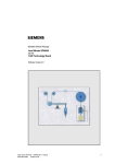
Configuring instructions and examples
4.13 Configuring example: Winder with closed-loop constant v
control
Applications
If there is no ”nip position” between an unwinder and a winder, which then
keeps the web velocity constant (e.g. for an ”inspection machine”), then
the winder must be operated in the pure closed-loop velocity controlled
mode.
For closed-loop velocity controlled winders, a web tachometer is
always required for the diameter computation.
Note
An example for a winder with closed-loop constant v control is shown in
Fig. 4-15.
<1>
The tension controller has no effect and its input is disabled with
H195=0.0. For H203 = 3.0, the closed-loop speed correction control is
selected as control type and the correction setpoint is now 0.0.
<2>
For the diameter computer, instead of the velocity setpoint, the web
velocity actual value from the web tachometer is used. The closed-loop
tension control must be enabled in order to enable the diameter
computer.
<3>
The diameter is calculated from the measured web velocity actual value
and the speed actual value of the shaft tachometer. The quotient of the
velocity setpoint and the actual diameter then provides the speed setpoint
for the winder.
<5>
The friction- and acceleration compensation are
supplementary torque setpoint after the speed controller.
<6>
A pulse encoder should always be used as web tachometer.
<7>
When the web breaks, the web tachometer signal goes to zero. In
accordance with the ramp-up/ramp-down time, parameterized using
H238, the diameter goes toward Dmin, and the winder speed increases.
entered
as
For H236=1, the diameter for winders only increases, i.e. when the web
breaks, the winder would continue to run at the same speed.
Axial winder SPW420- SIMADYN D -Manual
6DD1903-0AB0 Edition 05.01
91