1
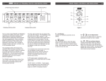
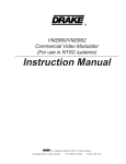
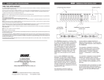
®
Distribution Amplifiers
1
DESCRIPTION
The R.L. DRAKE models DA100042, DA100032, DA8642, DA8632,
DA7543, and DA7533, are broadband distribution amplifiers designed for
indoor use in both residential and commercial buildings where RF signal
distribution in the frequency range of 49 to 1000 MHz is required. Each
model provides a very low distortion signal for a cable TV “drop”, the output
of an SMATV headend, or a small CATV headend. The amps are suitable
for both analog and digital - ATSC or QAM, amplification. The Gain and
Slope controls both have a range of 10 dB minimum and operate between
the preamp hybrid and the output hybrid to maintain a low noise figure over
a wide range of gain and slope settings. Double-sided, plated through hole,
glass epoxy, printed circuit boards, and SMT are used for low losses and
maximum reliability.
All models include a 20 dB gain integrated active return path amplifier,
and can provide a nominal unity gain passive return or no return path by
selection with internal jumpers.
Input and output test connectors are provided for convenient monitoring of
the signal path. The amplifier circuitry is designed for maximum stability,
low distortion, low noise figure, and is protected in a rugged aluminum
housing.
The unit operates from a nominal 26 VAC provided by the supplied
120 VAC, 60 Hz input AC Adapter.
Input equalizer and fixed attenuator options are available.
INSTALLATION
1) Unpack the distribution amplifier and AC adapter.
2) Mount the amplifier in the desired location, using the four mounting screw
holes on the sides of the amplifier. Vertical mounting on a wall with the
output end up is recommended for best ventilation and the coolest operation.
4) If the power transformer is to be wall mounted, install the included
bracket as shown. Then mount transformer to the wall.
WALL MOUNTING HOLES
OF MOUNTING BRACKET
OUT
SCREW HOLES FOR
WALL MOUNTING
(2 each side)
IN
TRANSFORMER
3) Route the power cable as needed to the power transformer. The cable
can be pushed between fins of the heat sink on the bottom of the amplifier.
Connect the power cable to the screw terminals on the power transformer.
SCREWS FOR FASTENING
MOUNTING BRACKET
TO TRANSFORMER CASE
5) Connect input and output cables to the amplifier.
6) Plug the power transformer line cord into a 120 VAC/60 Hz
power source.
7) Preset slope control fully clockwise.
8) While monitoring the output levels at the Output -30 dB test port, adjust
the Gain control for desired output at the high end of the band. Then
monitor the lowest channel and adjust slope control to equalize this channel
to the desired level (usually equal to but not higher than the high end of the
band). Since there can be a slight interaction between the gain settings, it
is advised to repeat this step a few times to ensure the desired levels are
attained.
NOTE: The -30 dB input and output test ports can be used to monitor input
and output levels. These are only accurate when the load is connected to
the amplifier output and power is on.
2
Internal Jumper Settings
RETURN PATH PROGRAMMING
There are three internal jumpers to be set. J1, J2, and J3. J1 and J3
program the signal path for the return path. If the return amplifier is desired
(20 dB gain), select the active return setting. This is the factory default. If a
unity gain return path is desired, select the passive return settings. If no
return path is desired, remove both J1 and J3. Jumper J2 is used to enable
DC power to the return amplifier. When selecting the active return, Jumper
J2 must be installed. If using the passive return or no return, remove
Jumper J2.
INTERNAL JUMPER SETTINGS 1) Unplug amp from the AC power source.
2) Remove top cover by loosening (but not removing) the 12 top cover
screws. Slide the top cover so the screws will slip through the larger screw
hole openings, then remove top cover.
A) JUMPER SETTINGS FOR ACTIVE RETURN PATH (Factory Setting)
POWER LED
JUMPER INSTALLED
RETURN PATH GAIN
ADJUSTMENT
B) JUMPER SETTINGS FOR PASSIVE RETURN PATH
POWER LED
JUMPER NOT INSTALLED
RETURN PATH GAIN
ADJUSTMENT
C) REMOVE ALL THREE JUMPERS FOR NO RETURN
Internal Jumper Settings, continued
A WORD CONCERNING INPUT LEVELS
It is important to keep the input level to the amplifier within an optimum range.
If the level is too high, higher nonlinear distortion will result and if the level
becomes too low, C/N might be less than desired. As a general rule, stay
within the guidelines below. This chart assumes a fully loaded analog channel
complement. Higher levels may be used if the channel loading is less. Also, if
the system is populated with around 70 analog channels and another 70 or 80
QAM channels that are at least 6 dB lower than the analogs, then the levels of
the analogs can be higher. Also, if the signals entering the distribution amp
are sloped, then the highest frequency channels can be set to higher output
levels that shown below for a 'flat' input.
INSTALLING FORWARD PATH INPUT ATTENUATOR
If input levels are enough to cause a high distortion level in the input
amplifier, a fixed input attenuator may be added. Remove top cover.
Choose an SXP type attenuator of the value required, and install at the
location indicated below. Remove the 0 dB wire jumper to allow insertion of
the attenuator. Carefully replace the top cover being sure that the spacer
mounted to the cover does not unseat the just installed attenuator. The
spacer should be directly over the attenuator when the cover is positioned
correctly. Tightens cover screws after positioning.
FORWARD PATH FIXED
INPUT ATTENUATION
LOCATION
A factory installed jumper is
installed here for no attenuation.
To install an input attenuator,
remove jumper and plug in a
"SXP" type attenuator rated for
the same or higher frequency as
the amplifier.
In general, install a fixed input attenuator if required to set the highest
frequency channels in the input to within the optimum range. Then set the
amplifier gain to achieve the desired output level, not to exceed the maximum
output level listed in the chart below. Then, if the low frequency channels are
above the optimum input level range, a fixed input equalizer can be installed
to drop the low frequency channels to within this range. Use the slope control
to make fine adjustments.
OPTIMUM INPUT
LEVEL FOR
LOWEST
NEL
MODEL
LOADING
DISTORTION
MAX INPUT
WITHOUT
INPUT
MAX OUTPUT
ADJUST GAIN
CONTROL
CHAN-
ATTENUATOR
3
IN
OUT
IN
OUT
GROUND
TO MAINTAIN
GROUND
DA7533
+10 to +15 dBmV
+18 dBmV
+44 dBmV
110 CH
DA7543
0 to +5 dBmV
+10 dBmV
+44 dBmV
110 CH
DA8632
+7 to +12 dBmV
+16 dBmV
+40 dBmV
129 CH
DA8642
-2 to +5 dBmV
+7 dBmV
+40 dBmV
129 CH
DA100032
+6 to +10 dBmV
+12 dBmV
+38 dBmV
150 CH
DA100042
-2 to + 5 dBmV
+ 7 dBmV
+38 dBmV
150 CH
If the input level is within the optimum input level window, distortion will be at
or below that which is specified. If a higher input level is supplied, add a fixed
input attenuator equal to the number of dB needed to reduce the level to be
within the optimum input range.
POWER LED
FORWARD PATH INPUT EQUALIZER LOCATION
A factory installed jumper is installed here for no
equalization. Install desired "QSA" type equalizer
here. If the equalizer is later removed, the jumper
must be reconnected between the IN and OUT
connections, keeping the length as short as possible.
INSTALLING AN INPUT EQUALIZER
Follow the same basic procedure as described above for the input attenuator
except that the equalizer is installed at the equalizer location shown above.
NOTE ABOUT COVER REMOVAL AND REPLACEMENT
This note only applies if the input attenuator has been installed. There is a
spacer mounted to the inside of the top cover that will be located directly
above the input attenuator. When removing or replacing the cover, be sure
that all of the cover screws are loosened several turns before moving the
cover. Be sure the attenuator is seated fully in its socket before reinstalling
the cover, and carefully place the cover in position with the spacer directly
over the attenuator, before retightening the screws.
4
Specifications and Warranty
SPECIFICATIONS COMMON TO ALL MODELS
Forward Gain Adjustment Range: 10 dB minimum.
Slope Control Adjustment (54 MHz): 10 dB minimum.
Input/Output Impedances: 75 Ohms.
Input and Output Monitor Ports: -30 dB.
Fixed Input Attenuator: Plug-in (SXP type) available.
Fixed Input Equalizer: Plug-in (QSA type) available.
Hum Modulation: -70 dB.
Frequency Coverage (return path): 5 to 36 MHz.
Active Return Path Gain: 20 dB minimum.
Return Path Input Attenuator: 0 to 10 dB adjustable.
RF Shielding: Leakage complies with FCC Part 76.
Power Requirement: 26 VAC from supplied transformer with
six foot amp-to-transformer cable.
ADDITIONAL SPECIFICATIONS FOR SPECIFIC MODELS
DA7533
Frequency Coverage (fwd path): 49 to 750 MHz.
Forward Gain: 33 dB.
Noise Figure: 7 dB maximum.
Return Loss, Input & Output: 14 dB.
Channel Loading: 110 CH.
Output Level (maximum per channel
for distortions listed below): +44 dBmV.
Input Level (maximum without using
fixed input attenuator): +18 dBmV.
Optimum Input Level Range: +10 dBmV to
+15 dBmV.
Nonlinear DistortionsComposite Triple Beat: - 58 dB.
Composite Second Order: - 58 dB.
Cross-modulation: - 62 dB.
Operating Temperature Range: - 20 deg. to + 60 deg. C.
Power Transformer: Supplied transformer has 120 VAC/
60 Hz ±10% input requirement at
35 W. Output is 26.3 VAC with screw
terminals for attaching power cable
from amplifier. Supplied 120 VAC
3-wire line cord is six feet long.
Size: 10.25" (26 cm) L x 7.25" (18.4 cm) W x
2.75" (7 cm) D.
Weight: 6 lbs. 12 oz. (3.1 Kg), including
AC adapter.
DA7543
49 to 750 MHz.
43 dB.
6.5 dB maximum.
14 dB.
110 CH.
DA8632
49 to 860 MHz.
32 dB.
7.5 dB maximum.
12 dB.
129 CH.
DA8642
49 to 860 MHz.
42 dB.
7 dB maximum.
12 dB.
129 CH
DA100032
DA100042
49 to 1000 MHz
32 dB
42 dB
8 dB maximum
7 dB max.
12 dB
12 dB
150 CH
150 CH
+44 dBmV.
+40 dBmV.
+40 dBmV
+38dBmV
+38 dBmV
+10 dBmV.
+16 dBmV.
+7 dBmV.
+12 dBmV
+7 dBmV
+0 dBmV to
+5 dBmV.
+7 dBmV to
+12 dBmV.
-2 dBmV to
+ 5 dBmV.
+6 dBmV to
+10 dBmV
-2 dBmV to
+5 dBmV
- 58 dB.
- 58 dB.
- 62 dB.
- 60 dB.
- 58 dB.
- 64 dB.
- 60 dB.
- 58 dB.
- 64 dB.
-62 dB
-60 dB
-66 dB
-62 dB
-60 dB
-66 dB
Output levels listed above are for all analog and flat channel loading. Output levels could be significantly higher when some channels are QAM , 6 dB below analog, and when slope is applied.
THREE YEAR LIMITED WARRANTY
R.L. DRAKE LLC warrants to the original purchaser this product shall be free from defects in material or workmanship for three (3) years from the
date of original purchase. During the warranty period R.L. DRAKE LLC or an authorized Drake service facility will provide, free of charge, both parts
and labor necessary to correct defects in material and workmanship. At its option, R.L. DRAKE LLC may replace a defective unit.
To obtain such warranty service, the original purchaser must:
(1) Retain invoice or original proof of purchase to establish the start of the warranty period.
(2) Notify R.L. DRAKE LLC or the nearest authorized service facility, as soon as possible after discovery of a possible defect, of:
(a) the model and serial number,
(b) the identity of the seller and the approximate date of purchase; and
(c) A detailed description of the problem, including details on the electrical connection to associated equipment and the list of such equipment.
(3) Deliver the product to R.L. DRAKE LLC or the nearest authorized service facility, or ship the same in its original container or equivalent, fully
insured and shipping charges prepaid.
Correct maintenance, repair, and use are necessary to obtain proper performance from this product. Therefore carefully read the
Instruction Manual. This warranty does not apply to any defect that R.L. DRAKE LLC determines is due to:
(a) Improper maintenance or repair, including the installation of parts or accessories that do not conform to the quality and specifications of the original
parts.
(b) Misuse, abuse, neglect or improper installation.
(c) Accidental or intentional damage.
- All implied warranties, if any, including warranties of merchantability and fitness for a particular purpose, terminate three (3) years from the date
of the original purchase.
- The foregoing constitutes R.L. DRAKE LLC’S entire obligation with respect to this product, and the original purchaser shall have no other remedy
and no claim for incidental or consequential damages, losses or expenses. Some states do not allow limitations on how long an implied warranty
lasts or do not allow the exclusions or limitation of incidental or consequential damages, so the above limitation and exclusion may not apply to you.
- This warranty gives you specific legal rights and you may also have other rights which vary from state to state. This warranty shall be construed
under the laws of Ohio.
CUSTOMER SERVICE AND PARTS TELEPHONE: (937) 746 6990
www.rldrake.com
TELEFAX: +1 (937) 806-1576
WORLD WIDE WEB SITE: http://
Programmable Reverse Path Step Attenuator
DRAKE MODELS DA100032, DA100042, DA7533, DA7543,
DA8632, and DA8642
These amplifiers are very versatile in regard to reverse (return)
path options.
If no return path is desired, remove jumpers J1, J2, and J3. These
may be stored inside the amplifier by plugging them into just a
single pin of the headers so that the one pin holds the jumper
mechanically but no electrical connection is made to other pins.
5
EXAMPLES
EXAMPLE 1
Assume that a particular installation requires a reverse path gain of
5 dB. Subtracting 5 from the nominal gain of 22 dB gives a result of
17 dB attenuation required to reduce the reverse path gain to 5 dB.
To reduce the reverse path gain by 17 dB, move the 16 dB
programmable attenuator jumper to the IN position. Then adjust the
REVERSE PATH GAIN adjustment counterclockwise to obtain the
additional 1 dB of attenuation.
If a passive return path is required with or without attenuation, set
jumpers J1 and J3 to the passive return path settings. Leave
jumper J2 disconnected. The REVERSE PATH GAIN adjustable
attenuator may be used to set up to approximately 12 dB of
attenuation in this path, if needed. At maximum gain setting, the
insertion loss of the passive return will be nominally 1 dB. The
programmable reverse attenuator jumpers have no effect when
using the passive return path.
When gain must be added to the reverse path, set jumpers J1, J2,
and J3 to the active return path settings. This revision of the Drake
DA series of distribution amplifiers now provides a programmable
reverse step attenuator that is programmable in steps of 2 dB
between 2 dB and 30 dB. This attenuator is located electrically
after the first stage of gain in the active reverse path amplifier. This
allows a low noise figure and excellent carrier to noise ratio to be
maintained even at low reverse gain settings. The use of this
attenuator will be equivalent to using fixed output attenuators in
other commonly used amplifiers. Fine adjustment of the reverse
path gain can be accomplished using the variable REVERSE
PATH GAIN adjustment.
(Jumper at the "16 dB" "IN" position)
EXAMPLE 2
Assume that an installation requires 15 dB of gain reduction in the
reverse path amplifier to achieve a gain of 7 dB. The step attenuator can be programmed for 12 dB (setting the 8 dB and 4 dB
jumpers both to ‘IN’) or to 14 dB (setting the 8 dB, 4 dB, and 2 dB
jumpers all to ‘IN’) and then adjusting the variable REVERSE
PATH GAIN control to reduce the gain the additional 1 or 3 dB. The
idea here is that one should set the step attenuator slightly less
than the attenuation needed so that there can always be some fine
adjustment of the variable gain control.
Set the gain using a combination of the programmable reverse
path step attenuator and the variable reverse path gain input
attenuator. Maximum reverse path gain is nominally 22 dB.
For reverse input signal levels around 15 dBmV or below, program
most of the needed attenuation using the programmable 2 dB step
attenuator and then fine tune the final dB or two using the variable
reverse path gain adjustment. If input levels are above 20 dBmV, it
is desirable to obtain as much of the needed attenuation as
possible, up to 10 dB, with the variable attenuator and then use the
step attenuator to obtain the rest.
PROGRAMMABLE REVERSE STEP ATTENUATOR SETTINGS
There are four internal jumpers used to set the programmable
reverse attenuation. Each jumper controls an attenuator. The four
attenuator values are 2 dB, 4 dB, 8 dB, and 16 dB. The total
attenuation is the sum of any attenuators that have jumpers set to
the ‘IN’ setting. When a jumper is set to the ‘OUT’ setting, that
attenuator is out of the circuit and is effectively set to 0 dB. With all
four programmable attenuators OUT and the REVERSE PATH
GAIN, variable input attenuator set to maximum gain, the active
reverse path gain is nominally 22 dB.
® is a registered trademark of R.L. Drake LLC .
(Jumpers at the
"4 db" and "8 dB" "IN" positions)
(Jumpers at the
"2 dB", "4 dB",
and "8 dB" "IN" positions)
SUMMARY
If reverse input levels are low, in the 0 dBmV area, use as little
attenuation at the reverse path gain input attenuator as possible.
This will maintain the best possible C/N ratio by keeping the
reverse path amplifier noise figure low. Obtain most gain reduction
of the reverse path amp by using the step attenuator. On the other
hand, if reverse input levels are high, say around 20 dBmV, you
can safely dial in 10 dB to 12 dB of attenuation with the input gain
adjustment without degrading the C/N. This will keep distortion
products low. Obtain the rest of the attenuation with the step
attenuator.
R.L. DRAKE LLC
FRANKLIN, OHIO 45005 U.S.A
P/N: 3852703 rev L-10-09
© Copyright 2009 R.L. Drake LLC