1
2
Internal Jumper Settings
RETURN PATH PROGRAMMING
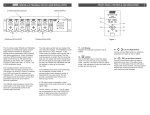
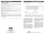
There are three internal jumpers to be set. J1, J2, and J3. J1 and J3
program the signal path for the return path. If the return amplifier is desired
(20 dB gain), select the active return setting. This is the factory default. If a
unity gain return path is desired, select the passive return settings. If no
return path is desired, remove both J1 and J3. Jumper J2 is used to enable
DC power to the return amplifier. When selecting the active return, Jumper
J2 must be installed. If using the passive return or no return, remove
Jumper J2.
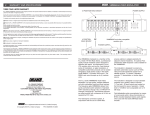
INTERNAL JUMPER SETTINGS 1) Unplug amp from the AC power source.
2) Remove top cover by loosening (but not removing) the 12 top cover
screws. Slide the top cover so the screws will slip through the larger screw
hole openings, then remove top cover.
A) JUMPER SETTINGS FOR ACTIVE RETURN PATH (Factory Setting)
POWER LED
JUMPER INSTALLED
RETURN PATH GAIN
ADJUSTMENT
B) JUMPER SETTINGS FOR PASSIVE RETURN PATH
POWER LED
JUMPER NOT INSTALLED
RETURN PATH GAIN
ADJUSTMENT
C) REMOVE ALL THREE JUMPERS FOR NO RETURN