1
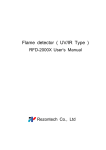
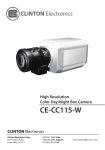
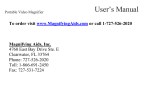
The lightning flash with an arrowhead symbol, within an equilateral
triangle is intended to alert the user to the presence of uninsulated
dangerous voltage within the product's enclosure that may be of
sufficient magnitude to constitute a risk of electric shock to persons.
The exclamation point within an equilateral triangle is intended to alert
the user to the presence of important operating and maintenance
(servicing) instructions in the literature accompanying the appliance.
INFORMATION - This equipment has been tested and found to comply with
limits for a Class A digital device, pursuant to part 15 of the FCC Rules & CE Rules.
These limits are designed to provide reasonable protection against harmful
interference when the equipment is operated in a commercial environment.
This equipment generates, uses, and can radiate radio frequency energy and, if
not installed and used in accordance with the instruction manual, may cause
harmful interference to radio communications.
Operation of this equipment in a residential area is likely to cause harmful
interference in which case the user will be required to correct the interference at
his own expense.
WARNING - Changes or modifications not expressly approved by the
manufacturer could void the user's authority to operate the equipment.
CAUTION : To prevent electric shock and risk of fire hazards:
◆ Do NOT use power sources other than those specified.
◆ Do NOT expose this appliance to rain or moisture.
This installation should be made by a qualified service person and
should conform to all local codes.
1
1/2" Ultra Low Light High Resolution Camera
■ Contents
Features
04
Precautions
06
Components and Accessories
08
Camera Operation
20
■ MENU
20
■ SWITCH
21
■ MAIN MENU
21
ㆍEXPOSURE
22
Overview
09
ㆍWHITE BALANCE
■ Front View
23
09
ㆍDAY / NIGHT
23
■ Side View
10
ㆍMOTION
24
■ Bottom View
11
ㆍPRIVACY
25
■ Rear View
12
ㆍOPTION
25
ㆍDISPLAY
27
ㆍSYNC
28
ㆍINITIAL
28
ㆍEXIT
28
Installation Procedures
13
■ Lens
ㆍUsing an Auto Iris Lens
ㆍUsing a C/CS mount Lens
13
■ Connecting a Monitor
17
■ Connecting Power
18
■ Control via RS-485 Interface
19
1/2" Ultra Low Light High Resolution Camera
2
Troubleshooting
29
Specification (AC24V / DC12V)
31
Specifications (AC230V)
32
3
1/2" Ultra Low Light High Resolution Camera
■ Features
Warning ■
Fine Picture in Ultra Low
Illumination.
DNR (Digital Noise Reduction)
1/2 inch CCD allows bright and high quality
images to be captured in ultra low light condition.
- Colour : 0.08Lux / F1.2
- B/W : 0.01Lux / F1.2
- Sens up : 0.001Lux / F1.2
The amount of low illuminance noise
has been significantly reduced, and the
signal-to-noise ratio (S/N ratio) as well as
horizontal resolution have been improved,
resulting in a clear and sharp image
display even in the dark.
Ultra High Resolution
Controlled by OSD Menu
By adopting a 410,000 pixel Sony CCD,
the camera produces clear picture quality
with a horizontal resolution of 540 TV lines
for colour, and 570 TV lines for B/W.
The camera can be controlled by
selecting text displayed on the monitor
screen.
The camera requires periodic inspection.
Contact an authorised technician to carry out the inspection.
Stop using your camera when you find it malfunctioning.
If the camera emits smoke or is unusually hot for a long period,
a fire may be caused.
Do not Install the camera on a surface that can not support it.
If the camera is installed on an inappropriate surface, it may fall
and cause injury.
Do not hold plug with wet hands.
Additional Functions
Filter Changeable Day & Night
SENS-UP, MOTION DETECTION,
MIRROR, SHARPNESS and SYNC
(INT/AUTO) functions are also available.
This camera has a function that automatically selects the mode that is
appropriate for daytime or night-time
conditions. The COLOUR mode operates in
daytime conditions to provide optimum
colours, and BW mode operates in nighttime
conditions to enhance the definition
of the image.
RS-485 Communication
Control Support
Remote OSD menu control via an RS-485 interface
is supported.
It could cause an electric shock.
Do not dis-assemble the camera.
It may result in an electric shock or other hazards.
Do not use the camera close to a gas or oil leak.
It may result in a fire or other hazards.
Electronic IRIS
The electronic IRIS function enables
continuous automatic control of the
shutter between 1/60(1/50)~1/120,000 seconds.
Privacy Function
The PRIVACY function conceals the
areas you do not wish to appear on
the screen.
1/2" Ultra Low Light High Resolution Camera
4
5
1/2" Ultra Low Light High Resolution Camera
■ Precautions
Do not install the camera in
extreme temperature conditions.
Do not install or use the camera in an
environment where the humidity is high.
Do not drop the camera and protect
it from physical shocks.
Only use the camera under conditions
where temperatures are between
-10˚C and +50˚C. Be especially
careful to provide ventilation when
operating under high temperatures.
It can cause the image quality to be
poor.
It can cause malfunctions to occur.
Do not install the camera under
unstable lighting conditions.
Do not touch the front lens of the
camera.
Never keep the camera pointed
directly at strong light.
It can damage the CCD.
Do not expose the camera to rain
or spill beverage on it.
Do not expose the camera to
radioactivity.
If it gets wet, wipe it dry immediately.
Liquids can contain minerals that
corrode the electronic components.
Severe lighting change or flicker can
cause the camera to work improperly.
1/2" Ultra Low Light High Resolution Camera
This is one of the most important parts of
the camera. Be careful not to leave
fingerprints on the lens cover.
6
If exposed to radioactivity the CCD
will fail.
ㆍIf the camera is exposed to spotlight or an object reflecting strong light,
smear or blooming may occur.
ㆍPlease check the power supply satisfies the normal specification before
connecting the camera.
7
1/2" Ultra Low Light High Resolution Camera
■ Components and Accessories
Overview ■
Front View
①
1. Day&Night CCD Camera
2. Auto Iris Lens Connector Plug
②
③
3. C-Mount Adapter
① Tripod Mounting Bracket Screw Hole
Used to fix the Tripod Mounting Bracket to the top of the camera.
② C-Mount Lens Adapter
Install this adapter to use a C-Mount Lens.
③ Back Focus Control Lever
Adjust Back Focus using this control lever.
4. Instruction Manual
1/2" Ultra Low Light High Resolution Camera
8
9
1/2" Ultra Low Light High Resolution Camera
■ Overview
Side View
Bottom View
⑤
④
④ Auto Iris Lens Connector
Used to connect Auto Iris Lens plug.
⑤ Tripod Mounting Bracket Screw Hole
Used to fix the camera onto a bracket or tripod.
The screw sizes for this hole are as follows:
L
1/4"-20 UNC (20 THREAD)
L:4.5mm±0.2mm (ISO standard),
or 0.197" (ASA standard)
The Tripod Mounting Bracket can be unscrewed and
installed on the top or bottom of the camera.
Make sure to use the Tripod Mounting Bracket when
fixing the camera to a bracket or tripod, otherwise the
camera may be unstable and the internal circuitry of
the camera may get damaged.
1/2" Ultra Low Light High Resolution Camera
10
11
1/2" Ultra Low Light High Resolution Camera
■ Overview
Installation Procedures ■
Rear View
⑩
⑪
⑥
⑦
⑧
⑫
⑬
⑨
⑥ OSD Setup Buttons
ㆍSET Button : Displays the menu on the screen. Press this button to confirm
status or after changing a selected item.
ㆍUp and Down Button : Used to move the cursor up or down in the menu
screen to select a desired menu item.
ㆍLeft and Right Button : Used to move the cursor left or right in the menu
screen or to change the value of the selected item.
⑦ D & N Input Port (GND : Colour, Open : B/W)
Switch to Day or Night Mode by connecting an external signal to this port.
⑧ MD Output Port
Motion detection signal is output through this port.
0V
There is motion
3±0.5sec
Lens
The lens is not supplied with this camera. Purchase a lens suitable for
the environment. This camera accepts an auto iris lens, and both
C-and CS-mount lenses.
Note
• It is recommended to use the DC type Auto Iris Lens to effectively
enjoy the major functions of this camera.
• Keep the lens surface clean, as the picture quality suffers if
there is dirt or fingerprints on the Lens.
Using an Auto Iris Lens
1. Strip 8mm of insulation from the end of the Auto Iris Lens cable..
approx. 8mm
+4.0V ~ +4.5V (less than 10mA)
There is motion
⑨ RS-485 Control Port
The SETUP MENU can be controlled via this port using an external controller that
supports RS-485 communications. For details, see page 19.
⑩ Power LED
When power is properly connected, the LED illuminates.
1/2" Ultra Low Light High Resolution Camera
⑪ Video OUT Port
Video signals are output through this port. Connect this port to the Video IN
port of a Monitor/DVR.
⑫ Auto iris lens selection switch
Used to change between DC or Video depending upon the type of
auto iris in use.
⑬ Power IN Port
Connections for Camera power, as specified for each model.
12
2. Strip 2mm of insulation from each of the cores of the cable.
approx. 2mm
13
1/2" Ultra Low Light High Resolution Camera
■ Installation Procedures
Using a C/CS mount Lens
3. Remove the cover of the Auto Iris Lens connector plug and solder the lens
cable to the connector pins of the plug.
• For a Video Drive Lens
Pin 1: Red (Power)
Pin 2: NC
Pin 3: White (Video Signal)
Pin 4: Black (Ground)
• For a DC Drive Lens
Pin 1: Damping Pin 2: Damping +
Pin 3: Drive +
Pin 4: Drive -
Before installing a lens, identify whether the lens to be installed is a C-Mount
or CS-Mount. This camera is set for a CS-Mount Lens by default. To install a
C-Mount Lens, a simple modification is required.
• When Using a CS Mount Lens
Remove the protective cover from the front of this product and turn the
CS-Mount Lens clockwise to install it. Focus the camera using the
CS-Mount Lens and Back Focus controls.
Lens cable
No. 3 Pin
No. 1 Pin
connector
No. 4 Pin
No. 2 Pin
Note
4. Fit the cover of the auto iris lens connector
plug, remove the protective CCD cover
from the front of the camera, and fasten
the Auto Iris Lens by turning it clockwise.
5. Focus the camera using the Auto Iris Lens
controls, combined with fine adjustment using
using the Back Focus control.
• Use a lens threaded as shown in the following figure. If the dimensions
of the thread are incorrect the camera could be damaged, or the lens
may not get installed firmly enough.
C-Mount Lens: 10mm or less
CS-Mount Lens: 5mm or less
• If the lens is too heavy the camera becomes unbalanced, which may
cause problems. Use a lens weighing less than 450g.
• When adjusting the Automatic Level Control (ALC) of an Auto Iris Lens,
use Av mode if available. If Pk mode is used the picture brightness
may change continuously.
Back Focus Control Lever
1/2" Ultra Low Light High Resolution Camera
14
15
1/2" Ultra Low Light High Resolution Camera
■ Installation Procedures
• Using a C-Mount Lens
1. Remove the protective cover at the front of this product and fit
the C-Mount Adapter, turn it clockwise to install it.
Connecting to a Monitor
Connect the video output terminal located on the rear of the camera
to the Monitor/DVR.
CCD Camera
2. Turn the C-Mount Lens clockwise to install it.
Monitor
• Since the connection procedure may differ depending on the type of monitor
or peripheral device to be connected, refer to the User Manual for the device
to be connected.
• Make sure to turn off the device to be connected before making any connections.
• Turn the 75Ω/Hi-Z switches of interim display devices to the Hi-Z position,
and the switches of any final device to the 75Ω position.
Intermediate
End monitor
3. Focus the camera using the C-Mount Lens and Back Focus controls.
CCD Camera
4. Set the lens selection switch, located on
the rear of the camera, to either DC or VIDEO,
depending on the type of auto iris lens being
used.
1/2" Ultra Low Light High Resolution Camera
16
17
1/2" Ultra Low Light High Resolution Camera
■ Installation Procedures
Connecting to Power
Control via the RS-485 Interface
Since power specifications differ depending on the model, make sure to check
your model name and specifications before connecting power.
You can connect power as shown in the following figure.
The camera can be controlled by using an external controller equipped with
RS-485 communications.
For AC / DC power
• Check the standard power requirement before connecting to power.
Dual Power Type
(AC 24V/DC 12V, AC 24V Class2)
DC Power Type (DC 12V, 500mA)
• To control using a DVR or keyboard controller
Connect the RS-485 cable (TRX+, TRX-) to the connection port of the 485
control board in the DVR or controller.
485 Control Board Connection Port
(+) CONNECTION TERMINAL (TRX+)
(- ) CONNECTION TERMINAL (TRX-)
AC90~230V-50Hz/60Hz 4.5W
AC90~230V~
50Hz/60Hz 4.5W
RS-485 Control Port
485+
485-
* RS-485 communication default initial values
Item
Initial value
Camera ID
1
BAUD RATE
9600
UART MODE
8-NONE-1
PET PKT
ENABLE
Note
• To control the camera use Pelco-D protocol.
(Go Preset 95 : Enters into OSD menu or Set key function)
When the resistance value of copper wire is at [20˚C(68˚F)]
Copper wire size(AWG)
#24(0.22mm2)
#22(0.33mm2)
#20(0.52mm2)
Resistance value( /m)
0.078
0.050
0.030
#18(0.83mm2)
0.018
Voltage drop(V/m)
0.028
0.018
0.011
0.006
• As shown in the table above, voltage decreases as the wire gets longer.
Therefore use of an excessively long adaptor output line for connection to
the camera may affect the performance of the camera.
※Standard voltage for camera operation : DC 12V±10%, AC 24V±10%
※There may be some deviation in voltage drop depending on the type of wire
and the manufacturer.
1/2" Ultra Low Light High Resolution Camera
18
19
1/2" Ultra Low Light High Resolution Camera
■ Camera Operation
■ SWITCH
■ MENU
[SET] : ON or OFF of OSD MENU
※It becomes a decision at the title screen.
MAIN MENU
EXPOSURE
ㆍLENS ㆍBRIGHTNESS ㆍBACKLIGHT
ㆍSHUTTER
ㆍAGC
ㆍSENSE UP
ㆍECLIPSE
ㆍDNR
WHITE BAL
ㆍWB MODE
ㆍRED CONT
ㆍBLUE CONT ㆍPUSH AUTO
DAY / NIGHT
ㆍD/N MODE
MOTION
ㆍDETECT MODE ㆍDETECT AREA
ㆍSENSITIVITY ㆍALARM TIME
ㆍAREA ㆍMASK
ㆍDOWN ㆍLEFT
ㆍLEVEL
ㆍRIGHT
OPTION
ㆍTITLE
ㆍNEGA/POSI
ㆍSHARPNESS ㆍMIRROR
ㆍZOOM
ㆍPAN/TILT
DISPLAY
ㆍTITLE
ㆍCAMERA ID
ㆍMOTION DET
ㆍBAUD RATE
SYNC
ㆍINT
ㆍAUTO
INITIAL
[LEFT] / [RIGHT] : SUB MENU ON or Decision
※When OSD MENU is OFF and PAN/TILT is ON, operate by [UP], [DOWN],
[LEFT], [RIGHT].
MOTION DETECT becomes invalid while moving PAN/TILT.
■ MAIN MENU
ㆍFILTER DLY
PRIVACY
[UP] / [DOWN] : UP or DOWN of Cursor
ㆍTOP
ㆍPHASE
MENU
EXPOSURE
WHITE BAL
DAY / NIGHT
MOTION
PRIVACY
OPTION
DISPLAY
SYNC
INITIAL
EXIT
+ ...
+ ...
+ ...
+ ...
+ ...
+ ...
+ ...
AUTO
NOT USE
ㆍEXPOSURE, WHITE BAL, DAY/NIGHT, MOTION, PRIVACY, OPTION and
DISPLAY has a SUB MENU.
[UP] / [DOWN] of Cursor. And SUB MENU is displayed by [LEFT] /[ RIGHT]
ㆍSYNC : AUTO or INT can be selected.
EXIT
ㆍWhen making INITIAL from USE to NOT USE, all data is initialized.
※It doesn't operate at NOT USE.
ㆍEXIT is non-displayed by [LEFT] / [RIGHT].
1/2" Ultra Low Light High Resolution Camera
20
21
1/2" Ultra Low Light High Resolution Camera
■ Camera Operation
EXPOSURE
WHITE BALANCE
WHITE BAL
EXPOSURE
LENS
BRIGHTNESS
BACKLIGHT
SHUTTER
AGC
SENSE UP
ECLIPSE
DNR
RETURN
DC
32
OFF
NOT USE
MID
X2
OFF
ON
WB MODE
RED CONT
BLUE CONT
PUSH AUTO
ATW
NOT USE
NOT USE
NOT USE
RETURN
ㆍLENS : ELC or DC/VIDEO can be selected.
ㆍBRIGHTNESS : 0 to 60 can be selected.
ㆍBACKLIGHT : OFF or ON can be selected.
ㆍSHUTTER : 1/60(NT), FLC, 1/250,500,1000,2000,4000,10000 can be selected.
※When LENS is DC, it is possible to select it. Another becomes NOT USE.
It becomes 1/60 at NTSC. It becomes 1/50 at PAL.
ㆍAGC : AGC OFF, LOW, MID, HIGH can be selected.
ㆍSENSE UP : OFF, x2, x4, x8, x16, x32 can be selected.
ㆍECLIPSE : If there is a high light installed in a limited environment such as an
apartment parking garage or gas station entrance, removing the high light makes
it possible to view car license plates efficiently.
- DAY : In normal daylight conditions, the HLC is not activated.
- NIGHT : If a high light that is larger than a certain size is present on the screen,
remove the high light to see license plates clearly.
MASKING AREA
ㆍWB MODE : ATW, AWC, MANUAL can be selected.
ㆍRED CONT : When it is MANUAL, 0 to 127 can be selected.
Another becomes NOT USE.
ㆍBLUE CONT : When it is MANUAL, 0 to 127 can be selected.
Another becomes NOT USE.
ㆍPUSH AUTO : When it is AWC, OFF to PUSH can be selected.
Another becomes NOT USE.
ㆍRETURN : It returns to the MAIN MENU.
DAY / NIGHT
DAY / NIGHT
D/N MODE
AUTO
FILTER DLY
5 SEC
RETURN
ON
OFF
ㆍDNR : This function reduces the background noise in a low luminance environment.
● OFF : Deactivates DNR. Noise is not reduced.
● ON : Activates DNR so that noise is reduced.
ㆍRETURN : It returns to the MAIN MENU.
1/2" Ultra Low Light High Resolution Camera
22
ㆍD/N MODE : AUTO, DAY, NIGHT, EXT can be selected.
ㆍFILTER DLY : When it is AUTO, 4 to 10 can be selected. When AGC is OFF,
NOT USE. Another becomes NOT USE.
ㆍRETURN : It returns to the MAIN MENU.
23
1/2" Ultra Low Light High Resolution Camera
■ Camera Operation
MOTION
PRIVACY
MOTION
DETECT MODE
DETECT AREA
SENSITIVITY
ALARM TIME
PRIVACY
OFF
+ ...
4
1 SEC
AREA
MASK
LEVEL
TOP
DOWN
LEFT
RIGHT
RETURN
ㆍDETECT MODE: OFF or ON can be selected.
※Turning on becomes invalid while displaying OSD.
However, it becomes effective only at MOTION AREA.
ㆍDETECT AREA: MOTION AREA is displayed.
ㆍSENSITIVITY: 0 to 8 can be selected.
ㆍALARM TIME : 1 to 60 can be selected.
ㆍRETURN : It returns to the MAIN MENU.
■ MOTION AREA
↑cursor ↑invalidity ↑effective
1
OFF
0
34
66
20
66
RETURN
ㆍAREA : 1 to 4 can be selected.
ㆍMASK : OFF or ON can be selected.
ㆍLEVEL : When MASK is ON, 0 to 15 can be selected.
※It set the same value regardless of a set value of AREA.
ㆍTOP : When MASK is ON, 3 to 124(NTSC) or 6 to 150(PAL) can be selected.
ㆍDOWN : When MASK is ON, 5 to 126(NTSC) or 8 to 152(PAL) can be selected.
ㆍLEFT : When MASK is ON, 0 to 187(NTSC) or 0 to 185(PAL) can be selected.
ㆍRIGHT : When MASK is ON, 2 to 189(NTSC) or 2 to 187(PAL) can be selected.
ㆍRETURN : It returns to the MAIN MENU.
OPTION
OPTION
ㆍA thick gray shows the cursor.
ㆍWhen it is transparent, the area becomes effective.
※Default is ALL transparent, it is ALL effective.
ㆍWhen it is light gray, the area becomes invalidity.
ㆍCursor moved by [LEFT] or [RIGHT].
ㆍWhen [UP] or [DOWN] is pushed, it becomes effective or invalid.
ㆍ[MENU] is returns to the MOTION.
※BLC automatically becomes effective on this screen.
1/2" Ultra Low Light High Resolution Camera
24
TITLE
NEGA/POSI
SHARPNESS
MIRROR
ZOOM
PAN/TILT
PHASE
+ ...
POSI
7
NOMAL
OFF
OFF
0
RETURN
25
1/2" Ultra Low Light High Resolution Camera
■ Camera Operation
■ POSITION
ㆍTITLE : TITLE is displayed.
ㆍNEGA/POSI : NEGA or POSI can be selected.
ㆍSHARPNESS : 0 to 15 can be selected.
ㆍMIRROR : NORMAL, MIRROR, VERTICAL, ROTATE can be selected.
ㆍZOOM : 0FF(x1) and ON1 to ON8(x4) can be selected.
When PAN/TILT is ON, it is NOT USE.
ㆍPAN/TILT : OFF or ON(x2) can be selected.
※When OSD MENU is OFF and PAN/TILT is ON, operate by [UP], [DOWN],
[LEFT], [RIGHT].
ㆍPHASE : You can select a desired phase between 0 and 524 when the SYNC.
menu is fixed to the 'AUTO' mode.
ㆍRETURN : It returns to the MAIN MENU.
TITLE
TITLE
TITLE
TITLE
ㆍTITLE position is changed by [UP], [DOWN], [LEFT], [RIGHT].
ㆍ[MENU] is returns to the TITLE.
■ TITLE
DISPLAY
TITLE
← → BS POS END
ABCDEFGH I J KLM
N O P Q R S T U VW X Y Z
a bc d ef g h i j k l m
n op q r s t u vw x y z
0 12 3 45 6 7 8 9 : ; .
* /+ - ~! #%&( ) " _
↓
DISPLAY
TITLE
MOTION DET
CAMERA ID
BAUD RATE
OFF
OFF
0
9600
RETURN
■ ■ ■ ■ ■ ■ ■ ■ ■ ■
ㆍIt moves by [UP], [DOWN], [LEFT] and [RIGHT].
ㆍCharacter is setting by [MENU]. The character from 1 to 10 can be set.
ㆍWhen [MENU] is pushed by(→/←), can move between the set characters.
ㆍWhen [MENU] is pushed by "BS", one character can be deleted.
ㆍWhen [MENU] is pushed by "POS", POSITION is displayed.
※Only when you set the character by one character or more.
ㆍWhen [MENU] is pushed by "END", return to the OPTION.
ㆍ"■" is brank.
ㆍ"-" is space.
1/2" Ultra Low Light High Resolution Camera
26
ㆍTITLE : OFF or ON can be selected.
ㆍMOTION DET : OFF or ON can be selected.
ㆍCAMERA ID : Determines the camera's identification number.
(between 0 and 255)
ㆍBAUD RATE : You can select 2400/9600 bps.
ㆍRETURN : It returns to the MAIN MENU.
27
1/2" Ultra Low Light High Resolution Camera
■ Camera Operation
Troubleshooting ■
SYNC
Two sychronisation modes are available, INTERNAL and AUTO.
In AUTO mode, it synchronises the video signal between cameras without
a synchronous generator. The line-lock synchronisation is only used in areas of
60Hz (NTSC Models) / 50Hz (PAL Models).
ㆍINT : Internal synchronisation
ㆍAUTO : External line-lock synchronisation
If there are problems with the camera operation, check the tables below. If
the problem persists, please contact the agent who supplied the product.
Problems
Troubleshooting
Nothing appears on the
screen.
ㆍCheck the power connection.
The video image is not
clear.
ㆍMake sure that the lens is clean.
Clean the lens with a clean lint free cloth or
brush.
ㆍAdjust the contrast control on the monitor.
ㆍMake sure that the screen is not exposed
directly to a bright light.
Re-position the camera if necessary.
The screen is dark.
ㆍAdjust the contrast control of the monitor.
ㆍIf there is an intermediate device, set the75ohm
Hi-z correctly, and also check the connections.
ㆍIf necessary, adjust the brightness level.
.
ㆍCheck the video signal line connection.
INITIAL
Returns to the level which was set by the manufacturer for shipment.
EXIT
Saves all the setting menus and then exits.
There is a problem with
the camera operation.
The camera surface is
too hot and black stripes
appear on the screen.
1/2" Ultra Low Light High Resolution Camera
28
ㆍCheck if an appropriate power source to
the camera complies with the manufacturer's
standard requirement, or if the voltage is
fluctuating. Check for ground loops.
29
1/2" Ultra Low Light High Resolution Camera
■ Troubleshooting
Specification (AC24V / DC12V) ■
Problems
The MOTION
DETECTION function is
not working.
Troubleshooting
ITEM
ㆍCheck if 'MOTION DETECTION' mode is
turned on.
Sensor
ㆍCheck the setting of the MD AREA.
Number of Pixel
NTSC
ICX 428AKL
ㆍCheck the 'WHITE BAL' setting.
(Please refer to page 23)
Vertical frequency
The screen is
flickering.
ㆍCheck if the camera is facing directly into
sunlight or fluorescent light.
Internal
15.734kHz
59.94Hz
Video out Level
1.0Vp-p/75Ω Video 0.714Vp-p Sync 0.286Vp-p
COLOUR mode is not
working.
ㆍCheck the frequency of power supply
(60Hz for NTSC, 50Hz for PAL).
ㆍCheck if the AGC menu is set to the OFF
position.
ㆍCheck if the AGC menu is set to the OFF
SENSE-UP function is not
position.
working.
ㆍCheck if the SHUTTER menu is set to
MANUAL mode.
1/2" Ultra Low Light High Resolution Camera
30
B/W : 570 TV Lines
0.286Vp-p
50dB Min. (AGC Correct Off)
Sensitivity
0.08Lux (Colour), 0.01Lux (B/W), 0.001Lux (Sens-up) / F1.2
Sense UP
Max 32 times
Correction
L/L mode is not
available.
50.00kHz
Colour : 540 TV Lines
S/N
ㆍHave you connected your camera to DC power
source? Connect it to AC power source.
15.625kHz
Resolution
Burst Level
L/L mode isn't able to
be selected.
752 X 582
2:1 Interlace
Synchronize
Horizontal frequency
ICX 429AKL
768 X 494
Scanning
Colours are not quite
right.
PAL
1/2" Ex-view colour CCD
0.45
AGC
IRIS Control
Electrical Shutter
+18dB Max.
Electrical IRIS / Lens IRIS (DC Lens)
1/60 (1/50) ~ 1/120,000sec.
Power Supply Voltage
AC24V / DC12V (+10%, -20%)
Power Supply Current
AC24V / DC12V (Max.350mA / Max.490mA)
Operating Temperature
-10˚C ~ 50˚C
Operating Humidity
90% RH max.
Weight
320g
31
1/2" Ultra Low Light High Resolution Camera
■ Specifications (AC230V)
ITEM
Sensor
Number of Pixel
NTSC
PAL
1/2" Ex-view colour CCD
ICX 428AKL
768 X 494
Scanning
Vertical frequency
752 X 582
2:1 Interlace
Synchronize
Horizontal frequency
ICX 429AKL
Internal
15.734kHz
15.625kHz
59.94Hz
50.00kHz
Resolution
Colour : 540 TV Lines
Video out Level
1.0Vp-p/75Ω Video 0.714Vp-p Sync 0.286Vp-p
Burst Level
B/W : 570 TV Lines
0.286Vp-p
S/N
50dB Min. (AGC Correct Off)
Sensitivity
0.08Lux (Colour), 0.01Lux (B/W), 0.001Lux (Sens-up) / F1.2
Sense UP
Max 32 times
γCorrection
0.45
AGC
IRIS Control
+18dB Max.
Electrical IRIS / Lens IRIS (DC Lens)
Electrical Shutter
1/60 (1/50) ~ 1/120,000sec.
Power Supply Voltage
AC230V
Power Supply Current
MAX. 4.5W
Operating Temperature
-10˚C ~ 50˚C
Operating Humidity
90% RH max.
Weight
1/2" Ultra Low Light High Resolution Camera
320g
32
Model : DN5241
1/2" Ultra Low Light
High Resolution Camera
Instruction Guide
GENIE CCTV LTD.
CCTV House, City Park, Watchmead, Welwyn Garden City, Hertfordshire, AL7 ILT
Tel : +44 (0) 1707 330541 Fax : +44 (0) 1707 330543
www.geniecctv.com