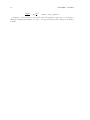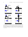
1
170
7.1
CHAPTER 7. DISCRETE PROCESS MEASUREMENT
“Normal” status of a switch
Perhaps the most confusing aspect of discrete sensors is the definition of a sensor’s normal status.
Electrical switch contacts are typically classified as either normally-open or normally-closed, referring
to the open or closed status of the contacts under “normal” conditions. But what exactly defines
“normal” for a switch? The answer is not complex, but it is often misunderstood.
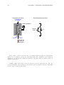
The “normal” status for a switch is the status its electrical contacts are in under a condition of
minimum physical stimulus. For a momentary-contact pushbutton switch, this would be the status
of the switch contact when it is not being pressed. The “normal” status of any switch is the way
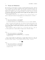
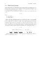
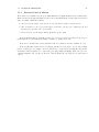
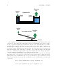
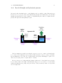
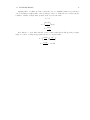
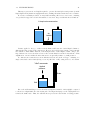
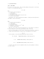
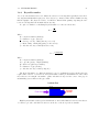
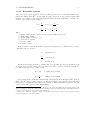
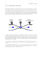
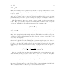
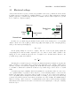
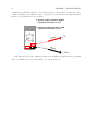
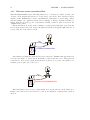
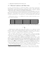
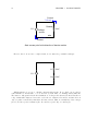
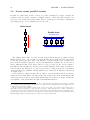
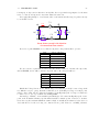
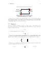
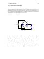
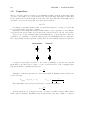
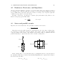
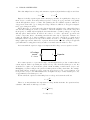
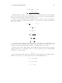
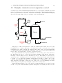
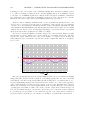
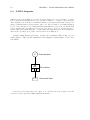
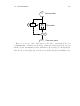
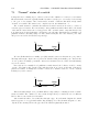
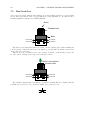
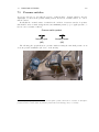
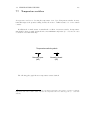
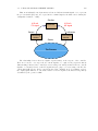
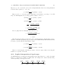
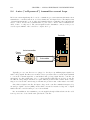
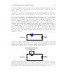
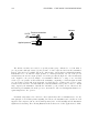
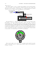
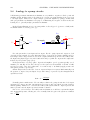
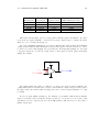
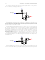
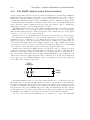
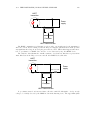
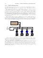
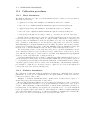
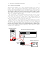
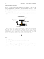
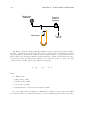
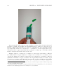
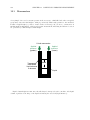
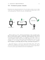
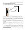
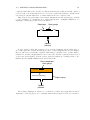
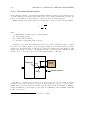
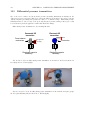
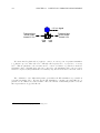
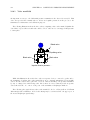
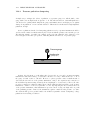
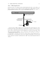
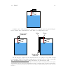
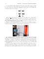
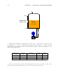
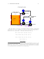
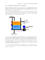
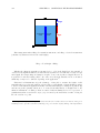
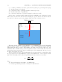
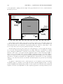
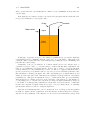
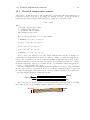
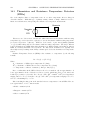
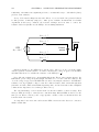
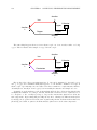
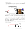
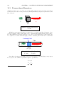
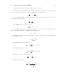
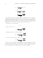
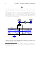
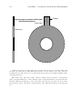
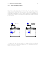
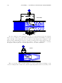
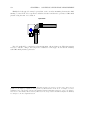
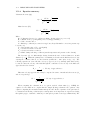
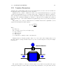
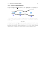
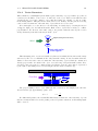
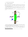
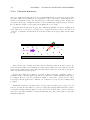
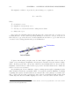
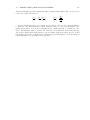
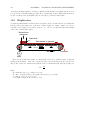
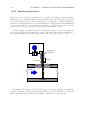
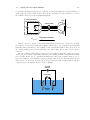
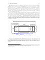
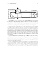
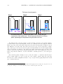
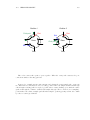
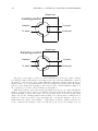
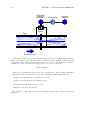
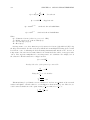
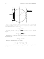
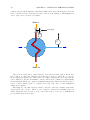
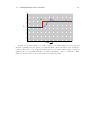
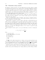
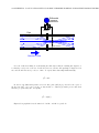
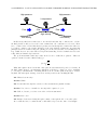
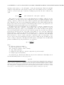
it is drawn in an electrical schematic. For instance, the following diagram shows a normally-open
pushbutton switch controlling a lamp on a 120 volt AC circuit (the “hot” and “neutral” poles of the
AC power source labeled L1 and L2, respectively):
L2
L1
Switch
Lamp
Normally-open contacts
We can tell this switch is a normally-open (NO) switch because it is drawn in an open position.
The lamp will energize only if someone presses the switch, holding its normally-open contacts in the
“closed” position. Normally-open switch contacts are sometimes referred to in the electrical industry
as form-A contacts.
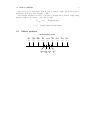
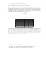
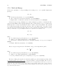
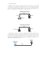
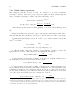
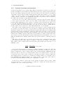
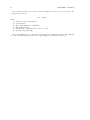
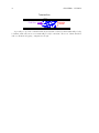
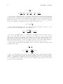
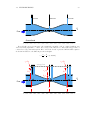
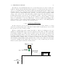
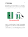
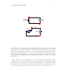
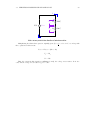
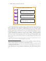
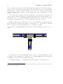
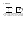
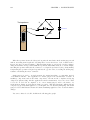
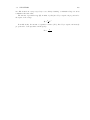
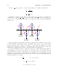
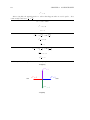
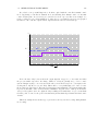
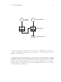
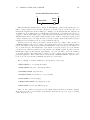
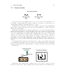
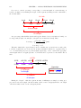
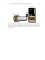
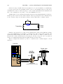
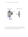
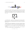
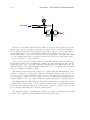
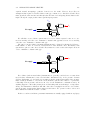
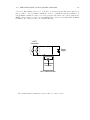
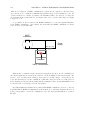
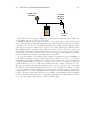
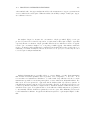
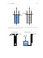
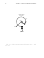
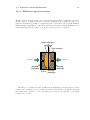
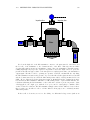
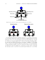
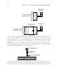
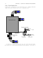
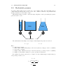
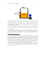
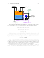
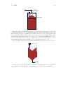
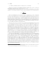
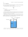
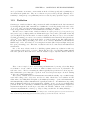
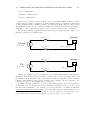
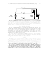
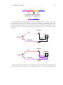
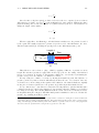
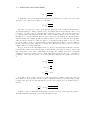
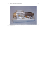
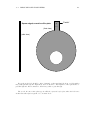
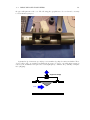
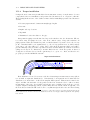
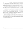
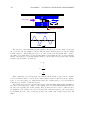
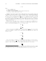
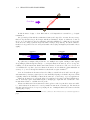
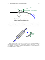
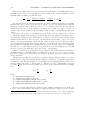
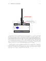
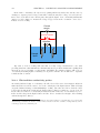
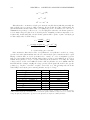
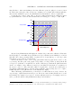
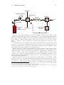
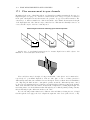
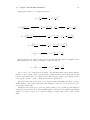
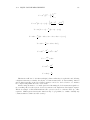
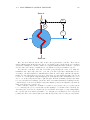
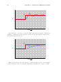
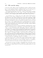
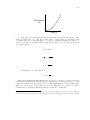
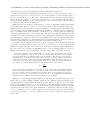
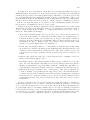
If we had used a normally-closed pushbutton switch instead, the behavior would be exactly
opposite. The lamp would energize if the switch was left alone, but it would turn off if anyone
pressed the switch. Normally-closed switch contacts are sometimes referred to in the electrical
industry as form-B contacts. :
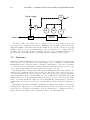
L2
L1
Switch
Lamp
Normally-closed contacts
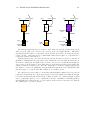
This seems rather simple, don’t you think? What could possibly be confusing about the “normal”
status of a switch? The confusion becomes evident, though, when you consider the case of a different
kind of discrete sensor such as a flow switch.
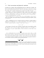
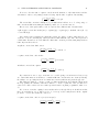
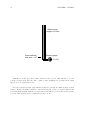
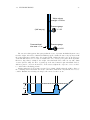
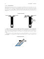
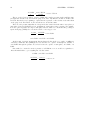
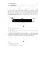
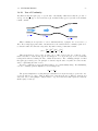
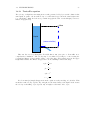
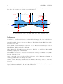
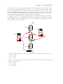
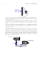
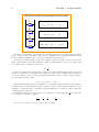
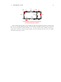
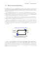
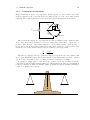
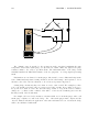
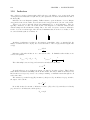
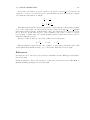
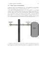
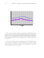
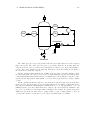
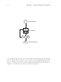
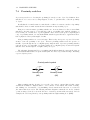
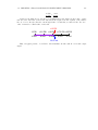
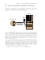
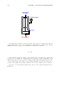
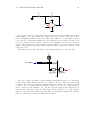
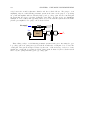
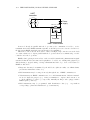
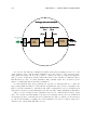
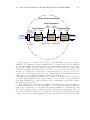
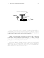
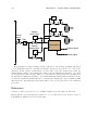
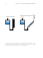
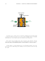
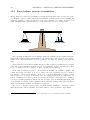
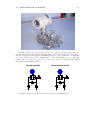
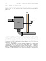
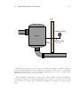
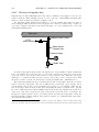
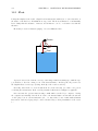
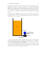
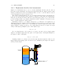
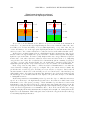
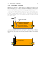
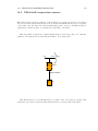
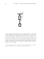
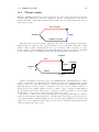
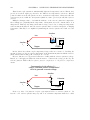
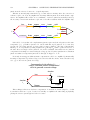
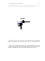
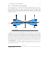
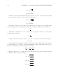
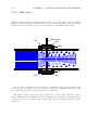
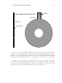
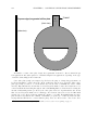
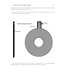
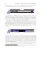
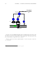
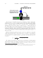
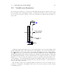
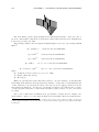
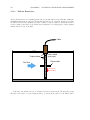
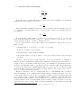
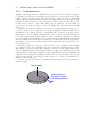
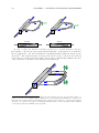
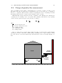
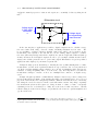
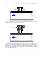
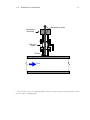
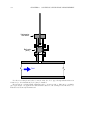
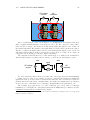
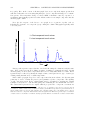
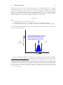
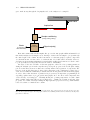
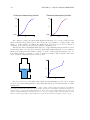
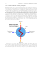
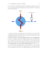
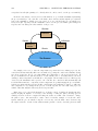
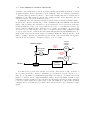
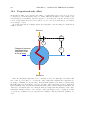
A flow switch is built to detect fluid flow through a pipe. In a schematic diagram, the switch
symbol appears to be a toggle switch with a “flag” hanging below. The schematic diagram, of course,
only shows the circuitry and not the pipe where the switch is physically mounted: