1
2.1.2 Dimensions sender and receiver
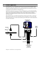
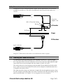
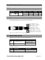
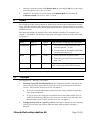
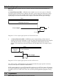
DoubleSense has one infrared transmitter (sender) and one photoelectric receiver that are
included in each delivery. The cable is shielded and 2 metres long for both sender and
receiver.
3-pole connector
Keep cable
straight ~5 cm
M8 - 0,75 mm fine thread
IR Sender
6
20
M8 nut
10-25 mm
13
Paper
0-5 mm
IR Receiver
4-pole connector
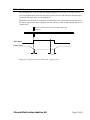
Diagram 3. Dimensions sender and receiver and location relative to paper.
2.1.3 Mounting the Sender and Receiver
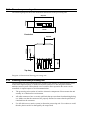
For optimal beam through capacity the sender should be mounted 10 – 25 mm from the
receiver and the paper surface should pass 0-5 mm above the receiver. Direct the light beam
90° to the paper surface. In order to keep the receiver away from stray light and direct light
sources the receiver can be mounted above the sender as well as vice versa.
The sender and receiver lens housing is partly threaded ∅8 mm and delivered with an M8nut, a washer and an O-ring attached. The units can for example be clenched mounted on a
U-shaped or a key hole cut out.
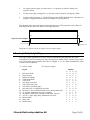
The cable must not be bent to any side since it might effect the throughbeam capacity. Keep
the cable straight (no bending angle) for at least 5 centimetres from the lens housing. Do not
pull or twist the cables. See chapter 2.3.2 for alignment check at installation.
©Svensk Elektronikproduktion AB
Page 7(43)