1
Chapter 7 - SPEC Program: Robot Specifications and Tuning
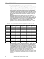
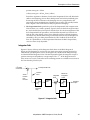
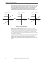
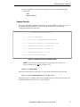
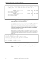
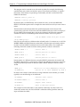
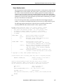
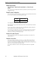
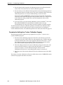
Sample scale factor calculations are shown below.
Example 1:
Linear motion achieved via the use of a lead-screw drive. The lead screw requires 2
revolutions per inch of travel. The encoder (800 lines per revolution) is mounted directly
to the back of the motor shaft and the lead screw is directly coupled (no gearing) to the
joint.
2 motor revs 800 × 4 counts
1 inch
251.9685 counts
------------------------------ × ----------------------------------- × --------------------- = --------------------------------------inch
motor revs
25.4 mm
mm
Example 2:
A jointed arm robot has a joint that rotates. The joint is driven through a harmonic drive
with a gear reduction ratio of 45 to 1. The encoder is mounted directly to the back of the
motor shaft and has 1000 lines per revolution.
45 motor rev 1000 × 4 counts 1 joint rev
500.0000 counts
------------------------------- × -------------------------------------- × ---------------------------- = --------------------------------------1 joint rev
motor rev
360 degrees
degree
Example 3:
A gantry mechanism contains five joints, and the last two contain multiple motor-to-joint
coupling. It is known that if joint 5 is held stationary and joint 4 is moved 1 degree, then
both motors 4 and 5 will move 400 counts. Also, if joint 4 is held stationary and joint 5 is
moved 1 degree, then motor 4 will not move, and motor 5 will move -1200 counts. The
scale factors are therefore as follows:
Joint 4 to motor 4 scale factor (counts/degree) = 400
Joint 5 to motor 4 scale factor (counts/degree) = 0
Joint 4 to motor 5 scale factor (counts/degree) = 400
Joint 5 to motor 5 scale factor (counts/degree) = -1200
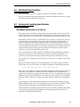
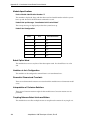
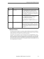
Encoder Counts Per Zero Index
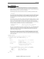
The “Encoder counts per zero index” parameter is defined as the number of encoder
counts between each zero-index on the encoder. Since there is normally only one index per
rotation of an encoder, it is usually the same as the number of counts per revolution (or
four times the number of lines per revolution).
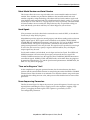
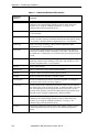
Some linear encoders have only one zero-index in the entire range of motion. In such a
case, the number of encoder counts per zero-index should be set to any value greater than
the number of counts in the encoder from end to end. Zero-index checking will still
function: any stray index pulse will cause an *Unexpected zero index* error and failure to
detect the single index at the correct encoder count will cause a *No zero index* error.
Other encoders have no zero-index at all. In that case, set the number of encoder counts
per zero index to 0.
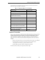
104
AdeptMotion VME Developer’s Guide, Rev B