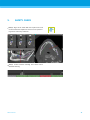
1
INSTRUCTIONS FOR USE
DEUTSCH
CONTENTS
5
2.
INTRODUCTION AND OVERVIEW
8
2.1
Intended use
8
2.2
Device description and features
8
2.2.1 Device variants and configuration
8
2.2.2 Principles of operation
9
2.2.3 Accessories and products used in combination
Indications
10
14
2.4
Contraindications
14
2.5
Precautions
14
2.6
Compatibility information
16
2.7
Further information
16
2.8
Installation
16
17
18
3.2
Views
19
3.3
Object tree
21
3.4
Plans
22
4.
STEP-BY-STEP CASE PLANNING
23
4.1
Define panoramic curve
24
4.2
Detect nerve canal
25
4.3
26
27
4.5
Plan abutments
28
4.6
Plan sleeves
29
4.7
Print protocols
30
5.
SAFETY CHECK
31
6.
DISTRIBUTORS AND SERVICE
33
7.
EXPLANATION OF THE SYMBOLS ON LABELS OR LEAFLETS
34
Dental Wings GmbH
РУССКИЙ
Plan implant
DANSK
4.4
NEDERLANDS
Toolbar
SVENSKA
3.1
PORTUGUÊS
3.
ESPAÑOL
2.3
ITALIANO
ABOUT THIS GUIDE
FRANÇAIS
1.
DEUTSCH
1.
ABOUT THIS GUIDE
These Instructions for Use are valid for the product life cycle of coDiag8.6 unless new instructions are published within this period.
Electronic Instructions for Use
8.6 Instructions for Use are provided in electronic form. A paper version can be requested from the manufacturer. For further information
and contact details see http://codiagnostix.com/ifu/
Disclaimer
software is designed for use by persons who have appropriate knowledge in implantology and surgical dentistry.
ITALIANO
ESPAÑOL
The user of
is solely responsible for determining whether or
not any product or treatment is suitable for a particular patient and circumstances. The user of co
is solely responsible for the correctness,
completeness and adequacy of all data entered into
software.
The user has to check the correctness and accuracy of planning with coDiagsoftware and to assess each individual case.
The selection of appropriate material as well as the correct fabrication of
scan or surgical templates lie within the sole responsibility of the user.
is not intended to be used in direct contact with the patient or
with life-sustaining devices.
Dental Wings products must be used in accordance with their accompanying
instructions for use. Improper use or handling of Dental Wings products will
void the warranty, if any, given for Dental Wings products. If you require additional information on the proper use of Dental Wings products, contact
your local distributor.
ABOUT THIS GUIDE
РУССКИЙ
DENTAL WINGS GMBH, ITS AFFILIATES OR DISTRIBUTORS DISCLAIM
REPRESENTATIONS AND WARRANTIES OF ANY KIND, WHETHER EXPRESS OR
IMPLIED, WRITTEN OR ORAL, WITH RESPECT TO THE PRODUCTS, INCLUDING
ANY WARRANTY OF MERCHANTABILITY, FITNESS FOR A PARTICULAR
PURPOSE, ERROR-FREE OPERATION OR NON-INFRINGEMENT, AND THE
PRODUCTS ARE SOLD “AS IS”.
5
5
Our maximum liability arising out of the products or their use, whether
based upon warranty, contract, tort or otherwise, shall not exceed the
actual payments received by us in respect of the purchase price thereof.
In no event shall we be liable for special, incidental or consequential
damages, including, but not limited to, loss of profits, loss of data or
loss of use damages, arising hereunder or from the sale of the products.
Please note that
software is subject to change. The user is obliged to study the latest developments of
regularly.
Product life cycle
The product life cycle of
software is 3 years. After expiration
of this time, the software may continue to function properly as long as configuration or hardware are not modified.
However, legal and regulatory requirements change at regular intervals. The
legal manufacturer does, therefore, not ensure compliance with the regulatory framework beyond the product life cycle period of 3 years (Declaration of
Conformity expires after 3 years). Update your software after the end of its
product life cycle to maintain regulatory compliance.
Input data
The performance of
depends on the quality and accuracy of
the CT and/or DVT scan as well as IO, model or impression scan imported.
The user is solely responsible to ensure that the quality of the imported data
is sufficient for proper performance of
Relevant anatomical
structures shall be visible in the scan. CT and DVT devices have to comply
with the recommendations of ICRP97 (International Commission on Radiological Protection).
Third party products
Within the scope of
the user works with third party manufacturers' products. Dental Wings GmbH, its subsidiaries, or distribution partners disclaim any liability for damages in connection with or arising from
planning with or usage of third party manufacturers' products.
Software license
software is protected by a License Agreement and may be
used or copied only in accordance with the terms of this agreement. It is illegal to copy or use
software on any medium except those
permitted in the License Agreement.
РУССКИЙ
Some of the features offered by
may require an additional license on your dongle. Contact your local distributor for more information.
Availability
Some of the products mentioned in this guide may not be available in all
countries.
6
ABOUT THIS GUIDE
DEUTSCH
Trade names and trademarks
DWOS® is a registered trademark of Dental Wings inc., Canada. coDiagand
are trademarks of Dental Wings GmbH,
Germany.
Straumann® and CARES® are registered trademarks of Straumann Holding
AG, Switzerland.
Microsoft®, SQL Server ®, Windows ®, Windows XP and Windows Vista are registered trademarks of Microsoft Corporation, USA.
Intel®
is a trademark of Intel Corporation registered in the U.S. and/or
other countries.
is a trademark of Advanced Micro Devices, Inc., USA.
App StoreSM is a service mark of Apple Inc., registered in the U.S. and other
countries.
ITALIANO
ESPAÑOL
Macintosh®, Mac®, Mac OS® and iPad® are trademarks of Apple Inc., registered in the U.S. and other countries.
is a trademark of SafeNet, Inc., USA.
CAMLOG® is a registered trademark of CAMLOG Biotechnologies AG,
Switzerland.
Steco® is a registered trademark of steco-system technik GmbH & Co. KG,
Germany.
bredent® is a registered trademark of Bredent Dentalgeräte und Materialien,
Fach- und Organisationsberatung Peter Brehm, Germany.
Copyright
Dental Wings documents may not be reprinted or published, in whole or in
part, without the written authorization of Dental Wings.
РУССКИЙ
ABOUT THIS GUIDE
7
7
2.
INTRODUCTION AND OVERVIEW
2.1
Intended use
is intended to be used as preoperative planning software for
dental implant placement.
2.2
Device description and features
is a 3D implant planning software allowing the import and
processing of the 3D CT/DVT scan dataset (DICOM standard). Based on the
finalized implant planning, the software allows for export of data for the production of surgical templates using the analog
table. In the analog
workflow the patient has to wear a scan template with reference pins during
the CT/DVT scan.
Working with the software is based on a patient’s medical image data such
as a CT (Computed Tomography) and DVT (Digital Volume Tomography) that
is processed by
after being transferred via CD/DVD, network
or various other storage mediums.
Planning is performed by the calculation of several views (such as virtual OPG
or a three-dimensional reconstruction of the image dataset), by the analysis
of the image data and the placement of implants, abutments and drilling
sleeves.
2.2.1.
Device variants and configuration
is available in a full version and a client version.
The Client is assigned to a
full version and can communicate
and export template data only through the assigned full version.
is an open software system. The library contains implant,
abutment and sleeve systems from several major manufacturers.
8
РУССКИЙ
For surgical template fabrication with the
is required
a template plan from
INTRODUCTION AND OVERVIEW
DEUTSCH
2.2.2.
Principles of operation
Implant planning with
guided surgery workflow.
is part of a
2.2.2.1. Analog workflow
The scan template contains information about the desired prosthetic outcome in form of radiopaque teeth
(visible in CT/DVT scan [3]). The scan template has to
be connected to the templiX plate containing three reference pins with the
in order to ensure the
link between digital implant planning and surgical template fabrication [4, 5].
[2] Scan template
fabrication
The patient is scanned wearing the scan template with
a commercially available 3D CT/DVT scanner.
[3] CT/DVT
scanning
The user can import the 3D dataset (DICOM) directly
into
planning software. Each implant is
positioned with respect to the patient’s anatomy and
the desired prosthetic outcome. After completion of
implant planning, the software provides the plan for
surgical template production with the
[5] as
well as further print protocols [6].
[4] 3D implant
planning
ITALIANO
[1] Master model
fabrication
ESPAÑOL
The master model represents the patient situation and
is the basis for the production of the scan and surgical
template [2, 5].
РУССКИЙ
INTRODUCTION AND OVERVIEW
9
9
The surgical template is produced with the
according to the template plan that is provided by
for each implant [4]. The surgical template contains the surgical sleeves that guide the surgical instruments and the implant [6]. There is no need
to produce a new template. If desired, the scan template [2] can be reworked into the surgical template.
[5] Surgical
template
fabrication
During guided surgery, the surgical template [5] is
fixed in the patient's mouth. Implant bed preparation
and guided implant insertion is done using appropriate guided instruments which have to be compatible
with the used implant and sleeve systems.
[6] Guided
surgery and
implant
insertion
2.2.3.
Accessories and products used in combination
The following products and accessories can be used in combination with
software:
Analog workflow using
and its accessories
Device for scan and surgical template fabrication by the dental laboratory.
accessories include:
Reference pin and templix reference plate
Devices for scan template production.
Scan control bar
Additional device for enhancement of quality of CT/DVT scans.
Generic sleeve positioner including closing lid
Device for sleeve positioning with
РУССКИЙ
10
INTRODUCTION AND OVERVIEW
DEUTSCH
2.2.3.1. Computer hardware and software requirements
ITALIANO
Optional components
DVD burner
Printer
Internet connection
An internet connection is required, for instance, for online updates, remote
support or online transfer.
Network connection
A network connection is required for using the optional Network Database
SQL or Network License.
ESPAÑOL
The following requirements are the minimum requirements recommended for
smooth operation of
However, under certain circumstances
the software might also run on other configurations.
Processor: Intel®
or AMD
64 X2
Main memory: 3 GB
Hard disk: 1 GB of free storage space for installation and approx. 50 MB
per patient case
Monitor
Text input device (e.g. keyboard)
Pointing device (e.g. mouse)
DVD drive
One free USB port
Minimum screen resolution: 1024 x 768 pixels
Operating system: Microsoft® Windows 7 recommended (other supported
operating systems: Microsoft® Windows XP, Vista)
PDF reader: Adobe Reader XI
Additional requirements for the
Network Database
Working with the Network Database SQL module requires a Microsoft® SQL
Server ®.
Additional requirements for the
Network License
An additional computer with a free USB slot running Microsoft® Windows
which acts as a dongle server (a server running 24/7 is recommended, but
not necessary)
A permanent (W)LAN connection to the dongle server while running
on the client computer
Optional: Shared network drive to store the database
РУССКИЙ
INTRODUCTION AND OVERVIEW
11
11
Network configuration requirements
Client: port 80, outgoing
Online Updater
Client: port 80, outgoing
Network Database SQL
To configure your network for use with SQL Server ®, see the information
provided by Microsoft or contact your Dental Wings support.
Network dongle
Client: TCP port 54237, UDP port 21945, both outgoing
Server: TCP port 54237, UDP port 21945, both incoming
Additional requirements for running
on Apple® Mac
®
OS X
Macintosh® computer with Intel® processor
Mac OS® X 10.6 or newer
‘Parallels Desktop’ for Macintosh including valid Windows ® license (software to be purchased separately)
Limitations regarding screen resolution
For optimum usability of
a screen resolution of 1680 x 1050
pixels (resp. 1280 x 1024 pixels for monitors 4:3) or higher with 96 dpi is recommended. Color resolution should be 32 bit, true color. The maximum resolution per view (3D reconstruction, virtual OPG, etc.) is 4096 x 3072 pixels.
2.2.3.2. Input data requirements
The software supports a wide range of image sources, including Computed
Tomography (CT) and Digital Volume Tomography (DVT) as well as surface,
intra-oral (IO) and impression scans from different manufacturers. It is also
possible to work with other sliced image data or volume data.
Supporting information for CT/DVT scans
The production of CT/DVT scans lies within the full responsibility of the radiologist or appropriately qualified personnel. However, the following requirements have to be observed to support image data processing and implant
planning with
РУССКИЙ
12
INTRODUCTION AND OVERVIEW
DEUTSCH
Preparation
All metal parts which are not fixed have to be removed from the patient’s
mouth.
When using the analog workflow with the
have the patient wear a
scan template with reference pins during radiology. The reference pins
have to be completely visible in the CT/DVT scan (one slice above the pin is
sufficient).
Make sure that all components attached to the scan template are firmly
fixed.
Clean or disinfect the template before placing it in the patient’s mouth.
Positioning
Align the occlusal plane to the scan plane in the best way possible.
ITALIANO
ESPAÑOL
Important CT scanning parameters
A gantry angle of 0° is recommended to achieve the best quality for image
reconstruction.
Block the opposite jaw bone using plastic material or cotton wool pads to
avoid artifacts around the reference pins.
Do NOT vary reconstruction parameters within a series (constant value for
X and Y axis).
Set a high-resolution bone algorithm:
“Inner Ear”
“Bone”
“High”
No “EDGE”!
Siemens e.g. “AK 97”
Elscint e.g. “Ultra High”
etc.
Parameters for a complete dataset when using dynamic mode:
Slices: 0.5 mm to 1.0 mm
When using spiral mode, reconstruction to 1.0 mm slices or less is recommended.
KV: approx. 110 to 130
mA: approx. 20 to 120
Storage of image data
Only axial slices are required.
DICOM III format, no raw data.
INTRODUCTION AND OVERVIEW
РУССКИЙ
Visualization of motion artifacts
In case of CT scans with scan template, motion artifacts can be visualized with
the help of a scan control bar.
13
13
2.3
Indications
is an implant planning and surgery planning software tool intended for use by dental professionals who have appropriate knowledge in
implantology and surgical dentistry. This software reads imaging information
output from medical scanners such as CT or DVT scanners. It allows preoperative simulation and evaluation of patient anatomy and dental implant placement.
provides printouts of template plans for the creation of surgical templates using a manually operated
table. The surgical template as well as a prior scan template are used in direct contact with the patient to facilitate accurate image registration within
and the
correct positioning and alignment of the implants as planned with the software.
2.4
Contraindications
is not intended to be used in direct contact with the patient
nor is it intended to be used with life sustaining devices.
must only be applied if additional radiation dose from 3D radiology (compared to conventional x-ray) can be justified. Contraindications
applying to other medical devices used within the scope of a guided surgery
workflow have to be taken into consideration.
2.5
Precautions
Please be aware that the user of
software is solely responsible for the correctness, accuracy and completeness of all data entered into
the
software.
Do not use datasets which can be created in spite of warning messages unless you fully understand the consequences of those warnings and are sure
that there will be no unacceptable risk for the correctness and accuracy of
your planning.
РУССКИЙ
Automatic nerve detection does not guarantee exact and accurate nerve
canal display. Make sure to always verify the correct position of the nerve
canal manually.
Always verify the correctness and accuracy of nerve canal display.
14
INTRODUCTION AND OVERVIEW
DEUTSCH
If nerve definition is not clear due to poor image quality, the dataset must not
be used.
Datasets with reference pins in both jaws (maxilla and mandible): The automatic pin detection of
EASY cannot distinguish between pins
in the maxilla and those in the mandible when scanned together. This can result in inaccurate planning. Accordingly, do not use the EASY mode to plan
datasets with reference pins in both jaws (maxilla and mandible).
Automatic reference pin detection does not guarantee exact and accurate
results. Make sure to always verify automatically detected reference pins
manually.
Always visually check and verify the correctness and accuracy of reference pin
detection.
ITALIANO
Printouts containing images of the dataset are not intended for diagnostic
purposes.
ESPAÑOL
If pin detection is not clear due to poor image quality, the dataset must not
be used.
Patient data presented on the iPad® are intended for presentation purposes
only. Do not use such data for diagnostic purposes.
The
verification should be printed directly from
calibrated printer.
to a
The selection of appropriate material as well as the correct fabrication of
scan or surgical templates lie within the sole responsibility of the user.
is not intended to be used in close proximity (within a distance of 1.5 meters) from the patient. Make sure to comply with all applicable
standards and technical regulations for any computer hardware used together with
For example:
Do not use multiple-socket extension cords.
Do not touch the patient and simultaneously plugs, ports or other connecting parts of the hardware.
Make sure that computer hardware which is used together with coDiagis at least 1.5 meters away from the patient.
INTRODUCTION AND OVERVIEW
РУССКИЙ
Make sure to clean or disinfect the template before placing it in the patient's
mouth.
15
15
2.6
Compatibility information
Archiving and restoring datasets in different versions of
cause compatibility problems.
can
Avoid using different versions of
If you have any problems,
contact customer service. In general, patient datasets from older versions of
can be opened with
8.6 (backward compatibility). Check your dataset carefully to avoid minor incompatibilities which might
lead to failures in the planning of dental implants and/or the production of
scan and surgical templates. Older versions of
however, cannot work with datasets from
8.6 (no forward compatibility of
older
versions).
2.7
Further information
Lab Manual
Help
2.8
Installation
Note
Do not plug the dongle into the computer until you are prompted to do so
by the installation program.
Steps for installation
1. Insert the installation medium into the computer.
2. If the installation process does not start automatically, start the program
manually by executing the file setup.exe on your installation medium.
3. Follow the instructions on the screen.
РУССКИЙ
16
INTRODUCTION AND OVERVIEW
DEUTSCH
3.
The software user interface is based on the Microsoft®
Windows ® standard allowing you to control the system
easily by mouse. To become familiar with the system
and the control elements such as buttons, check boxes
and edit controls, consult the user manual of your operating system.
Create dataset (DICOM)
Opens the DICOM Transfer dialog box to import
DICOM data (e.g. from a CD) and to create a patient dataset.
ITALIANO
ESPAÑOL
Open dataset
Opens the Patient Database (DICOM already imported).
Management
Management provides access to a
lot of administrative functions such as backup or
language setting.
Archiving and restoring datasets in different versions of
can cause compatibility
problems.
Main menu
Provides access to database-related functions,
other modules or License Management.
Updates and remote support
Shows information about updates and provides
access to remote support (active internet connection required).
РУССКИЙ
17
17
3.1
Toolbar
Tools of the interactive planning workflow.
Basic tools for view manipulation.
Menu with complete set of functions.
Customizing the toolbar
Right-click on the toolbar, select Adjust and drag the
icon onto or from the toolbar.
РУССКИЙ
18
DEUTSCH
3.2
Views
Views are color-coded and can be displayed in
other views as reference line with the respective
color.
Enlarge a view by clicking the Full Screen button
or double-click the title bar.
Move the Panoramic view inside and outside with
the right scroll bar.
ITALIANO
ESPAÑOL
Moving views
Enable the Move and Turn tool.
Move the view with the left mouse button.
Rotate the view with the right mouse button
(3D view only).
РУССКИЙ
19
19
Manipulating the views: most important tools
Description
Symbol
Enables/disables the Move and Turn tool.
Enables/disables the Localizer tool.
Enables/disables the Zoom tool.
Resets all views and fits contents to view box in all views.
Toggles the visibility of the Reference lines in all 2D views.
Aligns the cross-sectional, tangential and axial views with the axis of
the currently selected implant (at least one implant has to be
planned).
РУССКИЙ
20
DEUTSCH
3.3
Object tree
The object tree contains:
Tree functions (e.g. add, delete)
All the objects (e.g. implants, sleeves, nerve canals,
measurements)
Comment field
Tooth position pane (currently selected tooth position)
Provides all the information on the implant, abutment, sleeve and/or virtual tooth for the given tooth
position and allows to adjust them.
Density statistics
ITALIANO
ESPAÑOL
Moving/rotating objects
Select object in the object tree.
Activate the positioning mode.
Move object with the left mouse button.
Rotate object with the right mouse button (some objects only).
Objects: most important tree functions
Description
Symbol
Adds a new object (e.g. implant, measurement…).
Enables/disables the positioning mode.
As long as the positioning mode is not activated, the objects cannot be “touched” with the mouse.
Deletes the selected object.
РУССКИЙ
21
21
3.4
Plans
Working with different plans
Planning data are managed in plans. You may create several plans for one patient. Use the combo
box to browse your plans.
Plans can be:
Newly created, deleted and copied (select from
the Plan menu)
Protected against changes (select Plan > Properties from the main menu and tick Protect this
plan against changes). Such protection is reversible.
Finalized (select Plan > Finalize from the main
menu). No further modifications will be allowed.
Create a copy of the plan if you have to change
something subsequently.
РУССКИЙ
22
DEUTSCH
4.
STEP-BY-STEP CASE PLANNING
Starting
and loading a DICOM case
Start the
software; ensure that the
dongle is connected.
Insert the DICOM data you received from the CT/
DVT scanner into the computer's disc drive.
Click Create dataset (DICOM) on the start screen.
ITALIANO
ESPAÑOL
Select Import data from CD/DVD and click Import.
In case of any problems (error messages, warnings,
etc.), contact customer service.
Choose if you would like to plan a case for maxilla
or mandible. To plan both maxilla and mandible you
need to generate two separate plans.
switches to the standard planning
screen.
Caution
Please be aware that the user of
software is solely responsible for the correctness, accuracy
and completeness of all data entered into the coDiagsoftware.
Do not use datasets which can be created in spite of
warning messages unless you fully understand the
consequences of those warnings and are sure that
there will be no unacceptable risk for the correctness
and accuracy of your planning.
РУССКИЙ
STEP-BY-STEP CASE PLANNING
23
23
4.1
Define panoramic curve
Click the Panoramic Curve icon.
Grab the points with the left mouse button and
move the curve according to the patient’s anatomy.
To create additional points, click outside the existing
five basic points.
To delete additional points, right-click on the point
and select Delete Point from the context menu. The
five basic points cannot be deleted.
РУССКИЙ
24
STEP-BY-STEP CASE PLANNING
DEUTSCH
4.2
Detect nerve canal
Click the Nerve Canal icon to add the nerve canal
objects. The positioning mode will be activated
automatically.
In the object tree, select the nerve canal you want to
detect. Set the entry point foramen mentale and the
exit point foramen mandibule directly in the views.
Each nerve canal point can be moved and additional
points can be added in all views. To support nerve
canal detection, you can set as many nerve canal
points as you want and in any view you like.
ITALIANO
ESPAÑOL
Click Detect in the object tree.
automatically detect the nerve canal.
will
Caution
Always verify the correctness and accuracy of nerve
canal display.
Automatic nerve detection does not guarantee exact
and accurate nerve canal display. Make sure to always
verify the correct position of the nerve canal manually.
If nerve definition is not clear due to poor image quality, the dataset must not be used.
РУССКИЙ
STEP-BY-STEP CASE PLANNING
25
25
4.3
Click the
Registration icon.
Use the Automatic Search button to start automatic
pin detection.
Check your pin detection result for each reference
pin. To do so, activate the reference pin in the work
pane and check, in each single view, the correct
alignment of the blue pin with the white pin in the
scan. Adjust as necessary.
Adjusting reference pins with the mouse
Move the reference pin with the left mouse button.
Rotate the reference pin with the right mouse
button.
Confirm and accept reference pin validation.
Caution
Datasets with reference pins in both jaws (maxilla and
mandible): The automatic pin detection of coDiagEASY cannot distinguish between pins in the
maxilla and those in the mandible when scanned together. This can result in inaccurate planning. Accordingly, do not use the EASY mode to plan datasets with
reference pins in both jaws (maxilla and mandible).
Automatic reference pin detection does not guarantee
exact and accurate results. Make sure to always verify
automatically detected reference pins manually.
Always visually check and verify the correctness and
accuracy of reference pin detection.
26
РУССКИЙ
If pin detection is not clear due to poor image quality,
the dataset must not be used.
STEP-BY-STEP CASE PLANNING
DEUTSCH
4.4
Plan implant
Click the Add Implant icon. The Implant Database
opens.
Select the implant and the tooth position(s) where
the implant(s) shall be placed. Click OK and the
database closes.
ITALIANO
ESPAÑOL
Adjust the implant position. The positioning mode
is already activated.
Adjusting the implant
Move the implant with the left mouse button.
Rotate the implant with the right mouse button.
To support correct implant positioning, align the
views with the implant axis. This allows you to rotate
360° around the implant in the tangential view.
РУССКИЙ
STEP-BY-STEP CASE PLANNING
27
27
4.5
Plan abutments
Select an implant in the object tree.
Click the Edit Abutments icon.
The dialog box opens.
Switch to the Database tab and select the desired
abutment.
Click OK to apply your selection.
РУССКИЙ
28
STEP-BY-STEP CASE PLANNING
DEUTSCH
4.6
Plan sleeves
Select your implant in the object tree and click the
Edit Sleeves icon.
The dialog box opens.
Select a sleeve system from the list.
Adjust the parameters as desired.
Observe all instructions provided by the sleeve system
manufacturer.
ITALIANO
ESPAÑOL
Thoroughly verify all data before storing or using a
preset for a generic sleeve system.
Caution
Please be aware that the user of
software is solely responsible for the correctness, accuracy
and completeness of all data entered into the coDiagsoftware.
РУССКИЙ
STEP-BY-STEP CASE PLANNING
29
29
4.7
Print protocols
Click on the arrow of the Print icon in order to open
the menu.
Most important print protocols
Template plan: Required for surgical template fabrication with
verification: Required to check the setting
of the
coordinates and to verify the final
surgical template.
Surgical protocol: Protocol for using the guided instruments of Straumann® CARES® Guided Surgery.
Print all: Defines a selection of protocols to be printed in one step.
Caution
Printouts containing images of the dataset are not intended for diagnostic purposes.
The
verification should be printed directly
from
to a calibrated printer.
Note that a
verification protocol that is not
printed on a calibrated printer, but saved as PDF instead, will not be calibrated.
РУССКИЙ
30
STEP-BY-STEP CASE PLANNING
DEUTSCH
5.
SAFETY CHECK
Always align all 2D views with the implant axis and
rotate around the implant to ensure correct positioning and to avoid any collisions.
ITALIANO
ESPAÑOL
Always consult collision warning and critical nerve
distance warning.
РУССКИЙ
SAFETY CHECK
31
31
Always verify automatic nerve canal detection manually.
Always ensure correct fit of scan template during radiology.
Always give the information concerning CT/DVT
scans (accessible via the Help menu in the software)
to the radiologist before the first scan.
Control all automatic functions of the software.
After the planning is completed, always finalize the
plan (Plan > Finalize) to ensure that the plan cannot be modified later.
Check all printouts (template plan,
verification, etc.) to ensure that they belong to the corresponding finalized plan.
РУССКИЙ
32
SAFETY CHECK
DEUTSCH
6.
DISTRIBUTORS AND SERVICE
In case of questions, please contact your local distributor. Alternatively, contact [email protected] (in English or German).
ITALIANO
ESPAÑOL
РУССКИЙ
DISTRIBUTORS AND SERVICE
33
33
7.
EXPLANATION OF THE SYMBOLS ON LABELS OR LEAFLETS
Batch code
Caution, consult accompanying
documents
Catalog number
Use by
Sterilized using irradiation
Keep away from sunlight
Lower limit of temperature
Dental Wings products with the CE
mark fulfill the requirements of the
respective European Directives (see
Declaration of Conformity).
Upper limit of temperature
Consult instructions for use
Temperature limitation
Fragile, handle with care
Caution: Federal law restricts this
device to sale by or on the order of
a dental professional.
Keep dry
Do not re-use
This way up
Non-sterile
РУССКИЙ
34
EXPLANATION OF THE SYMBOLS ON LABELS OR LEAFLETS
www.dental-wings.com
Dental Wings GmbH
Duesseldorfer Platz 1
D-09111 Chemnitz
Germany
© Dental Wings GmbH 2013. All rights reserved.
01-03-2013 P003.02