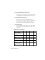
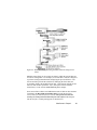
1
Copyright © 1999-2003 IO Industries Inc. All rights reserved. Video Savant® 4.0 User’s Guide Video Savant and DVR Express are registered trademarks of IO Industries Inc., registered in the U.S. Patent and Trademark Office. All other trademarks are the property of their respective owners. The contents of this manual and the associated Video Savant software are the property of IO Industries Inc. and are copyrighted. Any reproduction in whole or in part is strictly prohibited. Original printing January 16, 2003 PRINTED IN CANADA Table of Contents Chapter 1 Welcome to Video Savant ................................................................... 1 Understanding computer-based vision systems.............................................. 3 Image Capture Device ......................................................................................... 4 Device/Computer Interface.................................................................................. 5 Computer System ................................................................................................ 7 Application Computer Software ........................................................................... 7 Understanding real-time imaging..................................................................... 8 Understanding image capture to memory or hard disk.................................... 8 Understanding image buffers ...........................................................................9 Chapter 2 Getting Started ................................................................................... 11 Preparing to use your video camera and camera interface........................... 11 Installing Video Savant .................................................................................. 12 Configuring the computer for a USB software protection key............................ 14 Working with Device Selector........................................................................ 15 Selecting the default camera interface .............................................................. 15 Viewing camera interface driver release notes.................................................. 16 Installing an unlisted or updated camera interface driver .................................. 16 Working without a camera interface .................................................................. 17 Preparing a hard disk for video recording...................................................... 18 Single disk configuration.................................................................................... 19 Disk set managed by Disk Administrator / Computer Management .................. 21 Disk set managed by a hardware RAID controller............................................. 24 Starting Video Savant.................................................................................... 25 Exploring the work area................................................................................. 25 Image Viewing Area........................................................................................... 26 Control Panels ................................................................................................... 26 Displaying multiple Control Panels .................................................................... 28 DVR Control Panel ............................................................................................ 28 DVR Status Box................................................................................................. 29 Processing Control Panel .................................................................................. 30 Stream Filters Control Panel.............................................................................. 31 Output LUT Control Panel ................................................................................. 31 Display Control Panel ........................................................................................ 32 Camera Interface Control Panel ........................................................................ 33 Image File Types Control Panel ........................................................................ 34 Networking Control Panel .................................................................................. 35 Status Line......................................................................................................... 35 Quick menu........................................................................................................ 36 Table of Contents i Setting the camera interface video format..................................................... 37 Creating new video files................................................................................. 38 Opening an existing video file........................................................................ 40 Modifying the video file settings..................................................................... 41 Deleting video files......................................................................................... 42 Measuring video drive write-speed................................................................ 42 Selecting the camera mode........................................................................... 44 Changing the display of the DVR Status Box ................................................ 44 Capturing a single video frame...................................................................... 45 Capturing continuous (live) video frames ...................................................... 45 Capturing a sequence of video frames.......................................................... 46 Capturing consecutive lines from a line scan camera ....................................... 47 Playing back a video frame sequence ........................................................... 47 Playing back a video line scan sequence ...................................................... 48 Selecting an image viewing mode ................................................................. 49 Setting thumbnail size, layout, and display mode.......................................... 49 Zooming image display.................................................................................. 50 Erasing images.............................................................................................. 52 Printing images.............................................................................................. 53 Selecting an image buffer.............................................................................. 54 Selecting an image buffer sequence ............................................................. 54 Finding an image ............................................................................................55 Chapter 3 Working with Image Files .................................................................. 57 Importing images from files............................................................................ 57 Exporting images to files................................................................................ 59 Supported standard image file types ............................................................. 60 Importing images from unknown or unsupported file types ........................... 62 Exporting images to RAW file type ................................................................ 65 Adding new or updated file types................................................................... 66 Removing file types ....................................................................................... 67 Viewing file filter release notes .......................................................................68 Chapter 4 Video Acquisition and Recording..................................................... 69 Recording a video stream.............................................................................. 70 Setting the recording rate .................................................................................. 70 Stopping a recording (or playback).................................................................... 72 Displaying live video while recording................................................................. 74 Displaying live video at full screen size while recording .................................... 75 Marking events of interest while recording ........................................................ 78 ii Table of Contents Video recording control using an external trigger .......................................... 80 Accessing the trigger configuration controls...................................................... 82 Selecting the external trigger type ..................................................................... 83 Connecting an external trigger to the parallel port............................................. 83 Starting recording on external trigger ................................................................ 85 Stopping recording on external trigger............................................................... 86 Recording video frames prior to a starting trigger.............................................. 86 Recording additional data streams and real-time image processing ............. 88 Installing a stream filter...................................................................................... 90 Removing a stream filter.................................................................................... 91 Configuring a stream filter.................................................................................. 92 Viewing stream filter data after recording .......................................................... 92 Viewing stream filter data while recording ......................................................... 93 Exporting stream filter data to a file ................................................................... 93 Importing stream filter data from a file ............................................................... 94 Viewing stream filter release notes.................................................................... 95 Viewing stream filter general information........................................................... 95 Enabling/Disabling stream filters during recording ............................................ 96 Enabling/Disabling stream filters during live video capture ............................... 96 Stream filter library............................................................................................. 97 Using image compression ............................................................................. 99 Selecting a compression filter.......................................................................... 100 Configuring a compression filter ...................................................................... 101 Adding a compression filter ............................................................................. 102 Removing a compression filter ........................................................................ 103 Compression filter library ................................................................................. 103 Automating a set of video recording tasks using Python scripts.................. 104 Script commands ............................................................................................. 104 Creating a new script ....................................................................................... 105 Opening an existing script ............................................................................... 105 Saving a script ................................................................................................. 106 Running a script............................................................................................... 106 Viewing script output messages ...................................................................... 107 Example script ................................................................................................. 107 Setting special camera interface configuration options ................................108 Chapter 5 Video Display and Playback............................................................ 111 Playing back a video stream........................................................................ 112 Basic controls for video playback .................................................................... 112 Setting the playback frame rate ....................................................................... 113 Increasing the apparent playback frame rate by skipping frames ................... 115 Setting the playback line rate........................................................................... 116 Stopping playback ........................................................................................... 117 Table of Contents iii Displaying video at full screen size.................................................................. 117 Playing back video with automatic repeat........................................................ 118 Displaying stream filter data during playback .............................................. 118 Processing images during playback ............................................................ 119 Enabling/Disabling stream filters during playback ....................................... 120 Setting output look up tables ....................................................................... 121 Interactively setting a look up table.................................................................. 122 Resetting a look up table ................................................................................. 124 Setting a look up table from a file .................................................................... 124 Saving a look up table to a file......................................................................... 126 Automatically switching between look up tables during record/playback ........ 127 Working with foreign image formats (Bayer color, multi-tap, etc.) ............... 128 Geometric conversion...................................................................................... 130 Color space conversion ................................................................................... 132 Geometric and color space conversion ........................................................... 133 Selecting a conversion filter............................................................................. 133 Configuring a conversion filter ......................................................................... 134 Adding a conversion filter ................................................................................ 135 Removing a conversion filter ........................................................................... 136 Automating a set of video playback tasks using Python scripts .................. 136 Script commands ............................................................................................. 137 Creating a new script ....................................................................................... 138 Opening an existing script ............................................................................... 138 Saving a script ................................................................................................. 139 Running a script............................................................................................... 139 Viewing script output messages ...................................................................... 140 Example script ..................................................................................................140 Chapter 6 Image Processing and Analysis ..................................................... 141 Choosing a processing operation ................................................................ 142 Selecting images for processing.................................................................. 143 Organizing frequently used processing operations...................................... 144 Adding processing operations ..................................................................... 145 Removing processing operations ................................................................ 146 Setting a region of interest for image processing ........................................ 147 Setting the region of interest using the Quick menu........................................ 147 Setting the region of interest using the Processing Control Panel................... 148 Temporarily setting the region of interest to full size ....................................... 149 Displaying an outline of the current region of interest...................................... 149 Saving a region of interest ............................................................................... 150 Setting the image coordinate system........................................................... 151 Setting the origin.............................................................................................. 151 Setting the scale .............................................................................................. 152 iv Table of Contents Setting the orientation...................................................................................... 153 Saving coordinate system settings .................................................................. 154 Setting the color planes for image processing............................................. 154 Image processing operations....................................................................... 155 Arithmetic operations................................................................................... 158 Absolute difference .......................................................................................... 159 Add .................................................................................................................. 159 Add constant.................................................................................................... 160 Average ........................................................................................................... 161 Divide............................................................................................................... 162 Maximum ......................................................................................................... 163 Minimum .......................................................................................................... 164 Multiply............................................................................................................. 165 Multiply by fraction ........................................................................................... 165 Negate ............................................................................................................. 167 Subtract ........................................................................................................... 167 Boolean arithmetic, and bit-field operations................................................. 168 AND ................................................................................................................. 169 AND, OR, XOR with constant.......................................................................... 170 Bit shift ............................................................................................................. 171 NOT ................................................................................................................. 172 OR ................................................................................................................... 173 XOR ................................................................................................................. 174 Geometric operations .................................................................................. 175 Copy ................................................................................................................ 175 Mirror about vertical, horizontal or diagonal plane........................................... 176 Point to point measurements ........................................................................... 177 Rotate ±90°, 180° ........................................................................................... 184 Analysis, statistics and measurement operations........................................ 185 Blob counting and measurement ..................................................................... 185 Contour plot with path extraction ..................................................................... 188 Live pixel monitoring for points, lines, and areas............................................. 191 Pixel value frequency histogram plot with data extraction............................... 195 Pixel value viewing as numeric text................................................................. 199 Profile plot with data extraction........................................................................ 201 Projection plot for rows or columns with data extraction ................................. 203 Surface plot with grid point data extraction...................................................... 204 Interacting with Data and Graphic Viewers...................................................... 207 Transform operations .................................................................................. 209 Binarize............................................................................................................ 209 Convolution with predefined and custom masks ............................................. 210 Look up table ................................................................................................... 212 Morphology with erosion, dilation, boundary, open and close......................... 217 Table of Contents v Graphics drawing operations....................................................................... 218 Ellipse .............................................................................................................. 219 Line .................................................................................................................. 220 Rectangle......................................................................................................... 222 Sketch.............................................................................................................. 223 Text...................................................................................................................224 Chapter 7 Controlling Video Savant over a Computer Network ................... 227 Configuring the computer network............................................................... 228 Choosing a computer as the Master............................................................ 228 Selecting a computer for participation as a Slave........................................ 229 Changing configuration settings for a Slave ................................................ 232 Removing a Slave from participation........................................................... 233 Selecting computers for an operation.......................................................... 234 Restrictions on operations that can be disabled on the Master........................234 Chapter 8 Developing Custom Solutions with Video Savant SDK ................ 237 Approaches to customizing a solution ......................................................... 237 Types of Video Savant plug-in modules ...................................................... 238 Video Savant SDK features..........................................................................238 Chapter 9 Troubleshooting............................................................................... 239 Problem solving process.............................................................................. 239 Preliminary checklist........................................................................................ 239 Analyzing the problem ................................................................................. 240 Errors or warnings occur during startup .......................................................... 240 Single frame capture (Snap) fails .................................................................... 243 Continuous frame capture (Live) fails .............................................................. 246 Sequential frame capture (Video recording) fails............................................. 246 Video Savant takes a long time to start ........................................................... 248 My Video Savant 3.0 SDK application fails...................................................... 249 Receiving technical support......................................................................... 250 vi Table of Contents Chapter 1 Welcome to Video Savant T hank you for choosing IO Industries Video Savant® digital video recording software. When installed on a computer system with a compatible operating system and compatible hardware, Video Savant can record real-time1 image sequences to a computer’s memory or hard disk subsystem. Video Savant is compatible with the following operating systems: Microsoft® Windows® XP Professional Microsoft® Windows® 2000 Professional Microsoft® Windows® NT 4.0 SP61 For a list of supported camera interfaces (e.g. frame grabbers), visit IO Industries on the Internet at http://ioindustries.com. ❖ The Video Savant 4.0 Family: Video Savant Basic 4.0 • Interactive software for video recording, and playback. Video Savant Pro 4.0 • • • • 1 Interactive software for video recording, and playback; Recording and playback/viewing of additional data streams; Real-time or static image processing; and Centralized control of multiple computers, each running Video Savant, over a local area network. IO Industries DVR Express camera interface is supported under Windows XP Pro and Windows 2000 Pro, but not under Windows NT 4.0. Video Savant 4: Chapter 1 1 Video Savant SDK (Software Development Kit) 4.0 • Software libraries for development of custom solutions for video record/playback, data record/playback, and image processing. Video Savant RTL (Runtime License) 4.0 • Semi-interactive software that allows applications and Processing Libraries created using Video Savant SDK (Software Developer’s Kit) to be executed. Standard user-interface controls for video recording and playback are not included. Video Savant Viewer 4.0 • Low-cost software license for playback of video files and data streams recorded by Video Savant Basic, Pro, or SDK custom applications. Detailed Comparison of Features Feature Video recording to system memory or a hard disk subsystem (uncompressed or compressed) Video playback Video recording and playback from Python scripts Recording of additional data streams Playback/viewing of additional data streams Static image processing Real-time (host-based) image processing Frame and line scan (waterfall) image display - with zoom in/out, thumbnail display, and full-screen/windowed display modes 2 Welcome to Video Savant Basic Pro Viewer RTL Yes Yes N/A SDK Yes Yes Yes SDK Yes Yes N/A N/A SDK Yes N/A SDK SDK Yes Yes SDK SDK Yes N/A SDK SDK Yes N/A SDK Yes Yes Yes SDK Interactive Output Look Up Table controls with multiple tables and real-time LUT switching Centralized control of multiple computers on a local area network, each running Video Savant Basic, Pro or RTL Image file import and export Camera interface controls Yes Yes Yes SDK SLAVE MASTER or SLAVE N/A SLAVE Yes Yes Yes Yes Yes N/A SDK SDK Notes: SDK Indicates that the Video Savant SDK must be used to develop an application to provide access to the feature SLAVE Indicates this Video Savant license can be controlled from another computer on the local area network MASTER Indicates this Video Savant license can control SLAVE computers on the local area network N/A Indicates this feature is not available Understanding computer-based vision systems ❖ A complete computer-based vision system is composed of four general components: An Image Capture Device, such as a video camera, which outputs image information as an electronic signal; A Device/Computer Interface which takes the electronic signal containing the image information and converts it (if necessary) to binary data that the computer can directly manipulate and store; A Computer System which operates as the master controller of the vision system; and Application Computer Software containing a set of instructions which are issued to the host computer system and relayed to its Video Savant 4: Chapter 1 3 devices in order to receive, process, store and/or display image information for some useful purpose. Image Capture Device Video Savant is most often used in vision systems which use a video camera as the image capture device. A basic understanding of how this device operates is beneficial. A sensor in the video camera is exposed to light and generates an electrical response. The set of electrical responses registered over the surface of the sensor forms an electronic picture of the camera’s field of view. The camera outputs the electronic picture as an electronic signal, or video signal, over a time interval together with additional synchronization signals to mark the electronic start and end of each picture or video frame. Many different types of video cameras have been designed for a variety of vision applications. ❖ Four defining characteristics of video cameras are: Wavelength Sensitivity. The wavelength of light that the sensor responds to. Infra-Red sensors are popular for applications such as night vision and surveillance. However, most video cameras are designed to detect visible light. Visible light sensors are available for capturing monochrome or color pictures. Image Resolution. Also referred to as Frame Size, this is the spatial sampling frequency of the field of view. At higher resolutions, a more detailed representation of the field of view can be seen. For instance, high-resolution sensors are used in medical X-Ray imaging systems because a high degree of spatial precision is required. Frame Rate. The temporal sampling frequency of pictures. This refers to how many pictures are taken by the camera over a period of time. Higher frame rate sensors produce a more detailed record of motion in the camera’s field of view. For example, an object is moving at a speed of 1 meter/second directly across a camera’s 1 4 Welcome to Video Savant meter field of view. If a non-interlaced2 camera takes pictures at a frame rate of 30 frames/second, then it will capture 30 frames showing the object. A 200 frames/second camera with the same field of view would capture 200 frames showing the object, thereby generating a much more detailed record of the object’s motion. If the object was moving faster than 30 meters/second, the 30 frames/second camera would capture at most 1 frame showing the object. Video Format. The video format describes both the electronic signal type and the timing of the video signal output by the video camera. There are two electronic signal types that video cameras use to transmit their electronic image information: Digital Signals and Analog Signals. Analog type cameras output a signal that must be converted (digitized) by the Device/Computer Interface into a binary signal defining each pixel3 in the picture. Digital type cameras perform the digitization step internally and output a binary signal defining each pixel in the picture. Interestingly, some video cameras output both signal types. Analog cameras differ from one another with respect to timing and synchronization of the electronic signal they output. The same is true for digital cameras. Device/Computer Interface The Device/Computer Interface (camera interface) captures or acquires frames output by the video camera. The camera interface has evolved into 2 A non-interlaced camera frame is composed of a single scan of the field of view. An interlaced camera frame is composed of two scans separated in time, generating two subframes called an even field, and an odd field. The fields mesh together to form the even and odd lines of the field of view. At faster speeds of motion, the time lag between even and odd frames results in a blurring phenomenon known as the Interlaced Effect which is undesired when trying to record motion. 3 A pixel (picture element) is a number (or combination of numbers) describing the light measured at a point in an image. Pixels are sampled at regularly spaced intervals forming a matrix of data describing the complete field of view. A pixel is the smallest logical unit of visual information that can be used to build an image. The more pixels that are in an image, the higher its resolution. Video Savant 4: Chapter 1 5 many different forms in order to accommodate the different video formats produced by video cameras. Until recently, standard computer I/O ports were either not compatible or were too slow to function as camera interfaces for video cameras. Therefore a specialized class of devices, known as Frame Grabbers, was designed to be the camera interface in vision systems with video cameras. Frame grabbers are plug-in computer hardware modules which function mainly as nonstandard computer I/O ports4. New standards for video interfacing to computers such as Camera Link and Firewire® (IEEE-1394) are rapidly becoming the most popular methods for interfacing video cameras to computer systems. Firewire requires an extremely low-cost camera interface card, and is even a standard port on some computers. Camera Link is a higher speed, more sophisticated standard that requires a more expensive camera interface card. Not all cameras can be adapted to use these new camera interface standards, and specialized frame grabbers will continue to be used in many situations. IO Industries now offers a frame grabber, the IO Industries DVR Express, that is useful for video recording from very high data rate cameras. The DVR Express can acquire from Camera Link and LVDS digital video formats. An onboard SCSI controller chip transfers video data directly to SCSI disk(s) attached to the card. The DVR Express allows systems to be configured for continuous video recording to hard disk at data rates exceeding 1 GByte/sec. Visit the IO Industries website for more information. Communication between Video Savant and the camera interface (standard or non-standard) is handled by a special software module called a device driver. Video Savant issues high-level instructions to the device driver such as capture a video frame. The device driver responds by issuing a low-level set 4 Early frame grabbers did much more than acquire frames from video cameras. They had additional onboard capabilities such as memory for storing images, an image display capability, and a programmable processor for processing image data. The increased peripheral bus bandwidth and computing power of modern computer systems has resulted in the computer system providing image storage, display and processing. Some vision systems still require the use of frame grabbers with special capabilities, but the demand is declining as system computing power continues to increase. 6 Welcome to Video Savant of instructions, which tell the camera interface exactly how to carry out the task. Computer System The computer system is the master controller of the vision system. It directs the flow of image information into the system by passing instructions to the camera interface. Today’s vision systems are increasingly reliant on the resources of the computer system (as opposed to resources built into the camera interface). For this reason, the selection of a computer system with the correct configuration is critical. The computer system processor, memory (RAM), hard disk storage, display and peripheral I/O bus must be selected to match the requirements of the vision application. IO Industries can make recommendations for an appropriate configuration or direct you to a competent third party who can help. Contact IO Industries, or visit our website to find a sales representative in your area. Application Computer Software Video Savant running with a compatible operating system is the application computer software component of a computer-based vision system. Video Savant has been designed for vision systems requiring real-time digital video recording, video playback, real-time video processing and video postprocessing. Video Savant presents a consistent user-interface to the operator of the vision system, independent of the camera interface and video camera used. This device independence is achieved by the device driver software layer in the Video Savant architecture. A device driver has been designed for each camera interface that Video Savant supports. Visit the IO Industries website to see the current list of supported camera interfaces (e.g. frame grabbers). The most recent versions of these device drivers can be downloaded from our website free of charge. Video Savant 4: Chapter 1 7 Understanding real-time imaging Real-time imaging requires that a host computer system be able to perform some type of storage or processing operation on every frame of an incoming video stream. In the following discussion, a series of examples are given for which Video Savant can provide a solution. A common example of real-time imaging is to simply capture and store a raw video stream. Here, every frame in the video stream is sent either to system memory (RAM), or directly to a hard disk subsystem with no processing or display of the incoming stream. This is the default video recording mode of Video Savant. Viewing video during the recording process is an optional feature. Another common example is to append some additional data, such as the system time clock data, to the image data of each frame and then store the combined or mixed data streams. In this case only two data streams are mixed and stored, however there are cases when more than two streams must be mixed and stored. For instance, a user may wish to record video, GPS5, and sound data simultaneously. A more sophisticated use of real-time imaging is to process the frames of the incoming video stream, for example a background subtraction for an industrial part alignment operation, and then store the processed video stream. It may be required to mix in an additional data stream, such as status information describing whether the part is aligned or not, and store this information together with the video stream. Understanding image capture to memory or hard disk When video is captured by the host computer system, it must be stored somewhere. Video Savant has two storage modes: Memory mode and Disk mode. 5 GPS refers to Global Positioning System. Latitude, longitude and current time is received by the host computer via a satellite communication system. 8 Welcome to Video Savant In Memory mode, Video Savant stores the video frames in volatile system memory (RAM). In Disk mode, Video Savant stores the video frames in a hard disk subsystem. Memory mode has a higher maximum input bandwidth than Disk mode and can therefore accommodate video streams containing a higher data rate. High-resolution cameras and high frame rate cameras sometimes produce data rates which can only be recorded in Memory mode. Disk mode has a much larger storage capacity than Memory mode. Memory mode is typically used to record seconds of a video stream. Disk mode is used to record minutes or hours of a video stream. Understanding image buffers The frames of a video stream are stored in Image Buffers on the host computer. The data for image buffers is located in volatile system memory (Memory mode) or in a video file in a hard disk subsystem (Disk mode). Normally each image buffer contains a single video frame, however, in some special cases an image buffer can contain more than one video frame. There are some important considerations to be noted depending on which storage mode Video Savant is operating in. After Video Savant is started, the initial contents of the image buffers are normally set to zero in Memory mode. In Disk mode, the contents are the same as the last time the video file was used by Video Savant. When a new video file is created, the contents are initialized to zero. When Video Savant is closed, the contents of the image buffers are normally lost if operating in Memory mode. However, if you are running Video Savant in Memory mode and you wish to keep all of the images in the buffers for the next time you launch Video Savant, you need to change the Storage Type settings of your video file to not Disable save of RAM buffers to disk on shutdown. In Disk mode, the contents of image buffers are preserved in the video file and are accessible the next time Video Savant is started. (see Chapter 2, section Modifying the video file settings) Video Savant 4: Chapter 1 9 Chapter 2 Getting Started B efore you begin using Video Savant, the hardware and software of the vision system must be configured. The first step is to select a video camera and install a compatible camera interface in the computer system. After the hardware is installed, the vision system software must be configured. This chapter describes the procedures for configuring the vision system software. An introduction to the operation and features of Video Savant is included. Preparing to use your video camera and camera interface If your video camera has multiple modes of operation, you must ensure you have selected the desired mode. Some cameras have mode controls on the camera. Others have a computer communication interface for remotely selecting the desired mode. Consult the camera user manual for instructions. The camera interface for your vision system is either a standard computer I/O port (e.g. USB, Firewire/IEEE-1394, Ethernet), or a frame grabber. If you are using a standard computer I/O port, the camera user manual should describe how to configure the computer system port to work with the camera. If you are using a frame grabber, follow the steps given below. ❖ Setting up the frame grabber: 1. Ensure that the frame grabber is compatible with the operating system you wish to use. 2. Install the operating system. 3. Log in to the operating system as Administrator. Video Savant 4: Chapter 2 11 4. Install the software provided by the frame grabber manufacturer. Make note of the manufacturer’s software version number for future reference in case of difficulties. 5. Configure the software provided by the frame grabber manufacturer to work with your video camera. Refer to the documentation provided by the frame grabber manufacturer. 6. Run the frame grabber manufacturer’s test software and verify that frames can be captured from the video camera. 7. If you cannot successfully complete the above steps, contact the company from whom the frame grabber was purchased for assistance. Installing Video Savant If you have successfully completed the above steps, you are now ready to install Video Savant. ❖ Installation procedure: 12 1. Log in to the operating system as Administrator. 2. Locate the software protection key that came in the package along with the Video Savant CD-ROM. The key will be compatible with either a 25-pin parallel port or a USB port. Attach the key to the appropriate port. 3. If you have attached a USB software protection key for the first time, the Found New Hardware Wizard will appear. Follow the instructions in the section Configuring the computer for a USB software protection key in this chapter before proceeding with step 4 below if the Found New Hardware Wizard appears. 4. Insert the Video Savant CD-ROM in the computer’s CD-ROM drive. Getting Started 5. Wait a few seconds and the Video Savant setup program should automatically start. If the Video Savant setup program has not started after waiting 30 seconds, manually start the program by pressing Start button on the Windows desktop, choosing Run..., and opening SETUP.EXE in the root-directory on the Video Savant CDROM. 6. In the Video Savant setup program, choose Install Video Savant and follow the on-screen instructions to install Video Savant. 7. Install the driver for the Video Savant software protection key. If this driver is not correctly installed, Video Savant will not detect the presence of the key when started, and will operate in a restricted demonstration mode. We recommend that you install the driver for the key at this time. However, you can install it from the Video Savant CD-ROM at a later time. 8. Re-launch the Video Savant setup program if it is not already running (see steps 4 and 5 above). Choose Install Software Key Driver. 9. The Rainbow Technologies Sentinel window will appear. Access the Functions menu and select Install Sentinel Driver. 10. Press OK to accept the suggested path of the Sentinel files. 11. A message box will appear indicating that the driver has been installed. Click OK to close the message box. 12. If you are using a parallel port software protection key, close the Rainbow Technologies Sentinel window. You are now ready to use Video Savant! If you are using a USB port key, continue following these instructions. 13. Access the Functions menu and select Configure Sentinel Driver. 14. A list of all locations that the system driver will be looking for software protection keys will be displayed. Video Savant 4: Chapter 2 13 15. Double click on an entry in the list to view its settings. If the Port Type of this entry is USB, change the Use this port? setting to Yes, otherwise change the Use this port? setting to No. 16. Press OK to confirm your changes. 17. Repeat steps 15 and 16 for each entry in the list. 18. Press OK to close the list of locations that the system driver will be looking for software protection keys. 19. Close the Rainbow Technologies Sentinel window. You are now ready to use Video Savant. Configuring the computer for a USB software protection key If you will be using a USB software protection key instead of a parallel port software protection key, and have just plugged the USB key into the USB port on your computer for the first time, the Found New Hardware wizard will appear. Follow the steps below to install the driver for the USB software protection key. ❖ Installation procedure: 14 1. On the opening screen of the Found New Hardware wizard, press Next to continue. 2. Select Search for a suitable driver for my device (recommended). 3. Press Next to continue. 4. In the Optional Search Locations, choose CD-ROM drives. 5. Insert the Video Savant CD-ROM into the computer's CD-ROM drive. 6. The Video Savant installer will launch automatically. Click Exit to close the Video Savant setup program. Getting Started 7. On the Optional Search Locations screen of the Found New Hardware wizard, press Next to continue. 8. Windows may find the sntnlusb.inf driver file on the Video Savant CD-ROM. If not, browse to the \sentinel\win_nt\i386 directory of the Video Savant CD-ROM. 9. Press Next to accept the driver. 10. Press Finish to close the Found New Hardware wizard. Working with Device Selector ❖ Uses of Device Selector: Selecting the default camera interface (i.e. frame grabber) driver; Viewing the camera interface driver release notes; and Installing an unlisted or updated driver Before using a driver for the first time, it is recommended that you view the driver release notes to verify that the camera interface manufacturer’s software installed on the computer has the same version number as is specified in the Video Savant driver release notes. Selecting the default camera interface When Video Savant is started, it selects the Default Camera Interface as the active camera interface. ❖ To select the Default Camera Interface: 1. Highlight the name of the camera interface you wish to use. Video Savant 4: Chapter 2 15 2. Press the Set As Default button. Viewing camera interface driver release notes ❖ The camera interface Driver Release Notes describe: The driver version; The required version of the camera interface manufacturer’s software; The revision history of the driver; Supported features of the camera interface; General configuration instructions; Video format configuration instructions; and Special programming notes for Video Savant SDK users. ❖ To view the driver release notes: 1. Highlight the name of the camera interface you wish to use. 2. Press the Release Notes button. Installing an unlisted or updated camera interface driver There are two methods used to install an unlisted or updated driver. If you are installing a driver from the Video Savant CD-ROM, press the Install Unlisted … button in Device Selector (Start, Programs, Video Savant, Device Selector). Follow the on-screen instructions to install the driver. 16 Getting Started ❖ To install a driver from a file that was downloaded from the IO Industries website: 1. Press the Start button on the Windows desktop. 2. Choose Run. 3. Browse or enter the path to the driver file (this is a self-extracting executable). 4. Press the OK button and follow the on-screen instructions. Working without a camera interface The Virtual Frame Grabber is a special camera interface which simulates video capture from a video camera. During the installation of Video Savant, this driver is automatically installed. If you have not installed a camera interface device, or will not be using one, the Virtual Frame Grabber driver will allow you to start Video Savant for viewing and processing image data already stored on the computer. ❖ The Virtual Frame Grabber supports the following image types: 8 bit grayscale 16 bit grayscale (used for 9…16-bit pixel depths) 24 bit color RGB (8:8:8) 32 bit color RGBx (8:8:8:x) 16 bit color RGBx (5:5:5:1) 16 bit color RGB (5:6:5) 16 bit color YUV (4:2:2) Video Savant 4: Chapter 2 17 8 bit color Bayer mosaic Preparing a hard disk for video recording This procedure differs when using the DVR Express camera interface. Please consult the DVR Express User’s Manual. In this section, recommendations are made on how to configure a disk volume for video recording. Video recording to hard disk requires the use of a disk volume which is able to sustain a very high write speed. The sustained write speed must be faster than the data rate of the incoming video so that no video data is lost when recording to the volume. The most common method for optimizing write speed is to divide the write operation over a set of disks working in parallel. This technique is referred to as Disk Striping, or RAID 0. ❖ Three common disk configurations are: A single disk. A group of disks configured as a volume using Windows NT 4.0 Disk Administrator6 or Windows 2000 Pro / Windows XP Pro Computer Management7. A group of disks configured as a volume using a hardware RAID8 controller. 6 To start Disk Administrator: push the desktop Start button; select Programs; select Administrative Tools; and then select Disk Administrator. 7 To start Computer Management: push the desktop Start button; select Settings; select Control Panel; double-click Administrative Tools; double-click Computer Management. 8 RAID is an acronym, which stands for “Redundant Array of Independent Drives.” 18 Getting Started In all of these configurations, the disks should only be used for storing the video files generated by Video Savant. The disks should not be used to store program or data files from other applications. The following procedures will erase the contents of the video drive(s). If the video drives contain useful data, be sure to backup this data before proceeding. Single disk configuration ❖ To configure a single disk configuration in Windows XP Pro or Windows 2000 Pro: 1. Start Computer Management. 2. Select Disk Management from the tree on the left. 3. Right-click on the rectangular graphic located to the right of the disk corresponding to the video drive and select Create Volume. 4. Click Next; select Simple Volume as the Volume Type; and click Next again. 5. Choose a Drive Letter and click Next. 6. Choose Format this volume as follows, select the NTFS file system, choose allocation units of 4096, enter the desired volume label, and ensure that file and folder compression is disabled. 7. To skip scanning for bad sectors in the partition during formatting, enable Quick Format. Scanning for bad sectors is a very timeconsuming process, but it is recommended when using a new disk. 8. Click Next; verify your selected settings; and click Finish. 9. Close Computer Management and Control Panel. Video Savant 4: Chapter 2 19 10. Right-click on the Recycle Bin folder on the Windows desktop and select Properties. 11. Click the Global tab, and choose Configure drives independently. 12. Click on the tab associated with the video drive and choose Do not move files to the Recycle Bin. Remove files immediately when deleted. ❖ To configure a single disk configuration in Windows NT 4.0: 1. Start Disk Administrator. 2. On the View menu, select Disk Configuration. 3. Identify the disk to be used as the video drive. 4. Select the video drive disk by left-clicking on the rectangular graphic located to the right of the disk corresponding to the video drive. The appearance of a bold black border around the rectangle indicates the disk has been selected. 5. On the Partition menu, select Delete (The Delete operation will not be available if the disk is not currently assigned to a disk volume. In this case, this operation is not needed). 6. Select the video drive again (see above step 4). 7. On the Partition menu, select Create. 8. On the Partition menu, select Commit Changes Now. 9. Select the video drive again (see above step 4). 10. On the Tools menu, select Format. 11. Under File System, select NTFS. 12. Under Allocation Unit Size, select 4096. 20 Getting Started 13. To skip scanning for bad sectors in the partition during formatting, enable Quick Format. Scanning for bad sectors is a very timeconsuming process, but it is recommended when using a new disk. 14. Enable Compression should be disabled. 15. A Volume Label can be entered, although it is not required to do so. 16. Verify again that all settings for the format operation are correct. 17. Press the Start button to format the video drive. 18. Close Disk Administrator. 19. Right-click on the Recycle Bin folder on the Windows NT desktop and select Properties. 20. Click the Global tab, and choose Configure drives independently. 21. Click on the tab associated with the video drive, and choose Do not move files to the Recycle Bin. Remove files immediately on delete. Disk set managed by Disk Administrator / Computer Management ❖ To configure a disk set managed by Computer Management in Windows XP Pro or Windows 2000 Pro: 1. Start Computer Management. 2. Select Disk Management from the tree on the left. 3. In the lower portion of the display, locate the disks that you wish to include in the set and ensure that they are all indicated as being Dynamic. Video Savant 4: Chapter 2 21 4. If any of the disks are indicated as being Basic, right-click on them and select Upgrade to Dynamic Disk. 5. Right-click on one of the disks to be included in the set and select Create Volume. 6. Click Next; select Striped Volume as the Volume Type; and click Next again. 7. Select all of the disks to be included in the set by left-clicking them in the list on the left and clicking Add. When you have selected all of the disks for the set, click Next. 8. Choose a drive letter and click Next. 9. Choose Format this volume as follows; select the NTFS file system; choose allocation units of 4096; enter the desired volume label; and ensure that file and folder compression is disabled. 10. To skip scanning for bad sectors in the partition during formatting, enable Quick Format. Scanning for bad sectors is a very timeconsuming process, but it is recommended when using a new disk. 11. Click Next, verify your selected settings, and click Finish. 12. Close Computer Management and Control Panel. 13. Right-click on the Recycle Bin folder on the Windows desktop and select Properties. 14. Click the Global tab, and choose Configure drives independently. 15. Click on the tab associated with the video drive and choose Do not move files to the Recycle Bin. Remove files immediately when deleted. 22 Getting Started ❖ To configure a disk set managed by Disk Administrator in Windows NT 4.0: 1. Start Disk Administrator. 2. On the View menu, select Disk Configuration. 3. Identify the set of disks to be used as the video drive. 4. Select the first video drive disk in the set of disks by left-clicking on the rectangular graphic located to the right of the disk. The appearance of a bold black border around the rectangle indicates the disk has been selected. 5. On the Partition menu, select Delete (The Delete operation will not be available if the disk is not currently assigned to a disk volume. In this case, this operation is not needed). 6. Repeat the above steps 4 and 5 for each of the other disks in the set of disks assigned to the video drive. 7. Select the complete set of disks to be used as the video drive by pressing and holding down the Control key on the keyboard while left-clicking on the rectangular graphic located to the right of each video drive disk. The appearance of a bold black border around the set of rectangles indicates the disks have been selected. 8. On the Partition menu, select Create Stripe Set. 9. On the Partition menu, select Commit Changes Now. 10. Select the video drive again (see above step 4). 11. On the Tools menu, select Format. 12. Under File System, select NTFS. 13. Under Allocation Unit Size, select 4096. Video Savant 4: Chapter 2 23 14. To skip scanning for bad sectors in the partition during formatting, enable Quick Format. Scanning for bad sectors is a very timeconsuming process. It is recommended when using a new disk. 15. Enable Compression should be disabled. 16. A Volume Label can be entered, although it is not required to do so. 17. Verify again that all settings for the format operation are correct. 18. Press the Start button to format the video drive. 19. Close Disk Administrator. 20. Right-click on the Recycle Bin folder on the Windows NT desktop and select Properties. 21. Click the Global tab, and choose Configure drives independently. 22. Click on the tab associated with the video drive, and choose Do not move files to the Recycle Bin. Remove files immediately on delete. Disk set managed by a hardware RAID controller Hardware RAID controllers generally allow a selection of RAID levels. A software RAID configuration utility, provided by the RAID controller manufacturer, allows the RAID level to be selected along with other operational parameters. For video recording, RAID level 0, also referred to as Disk Striping, is recommended because it provides the fastest write speed, although no data redundancy9 is implemented. 9 Data redundancy allows data on a disk volume to be recovered in the event of a catastrophic failure of one or more of the disks in the disk volume. The different RAID levels offer varying degrees of protection. 24 Getting Started If data redundancy is required, other levels of RAID can be used. In general, increased data redundancy reduces both the effective storage capacity of the disk volume and the write speed of the disk volume. Other operational parameters which affect write speed include Stripe Size, and Write Back Cache. Stripe Size should be set to the highest possible value. Write Back Cache should be enabled. Refer to the documentation supplied by the RAID controller manufacturer for a discussion of these and other parameters which affect performance. Once the RAID set is configured using the manufacturer’s software utility, the set of disks will appear as a single disk entry under Windows Disk Administrator. The procedure for preparing the disk volume is the same as is listed above for a Single Drive Configuration. Starting Video Savant If you have successfully performed the hardware and software configurations required for your vision system as described in the preceding sections, then you are ready to start Video Savant. Be sure that your camera interface (e.g. frame grabber) is specified as the default camera interface in the Device Selector utility. To start Video Savant, open the Video Savant folder, and then open the Video Savant application. If Video Savant starts without any warning or error messages, you may proceed with the remaining sections of this chapter. If you are experiencing problems starting Video Savant, see Chapter 9 for guidelines on troubleshooting. Exploring the work area This section is intended as a brief introduction to the features of Video Savant. The Video Savant work area appears as shown below. Video Savant 4: Chapter 2 25 Figure 2.1: The Video Savant work area. Image Viewing Area The Image Viewing Area can display image thumbnails or full size images. Full size images can be zoomed in or out by different magnification factors. Control Panels The primary point of control in the Video Savant user-interface is the set of control panels located at the bottom of the Video Savant window. 26 Getting Started ❖ The purpose of each control panel is as follows: DVR (Digital Video Recording) Control Panel. Supports the following operations: video recording; video playback; live image capture (live); and single frame image capture (snap). Processing Control Panel. Provides image processing and analysis functions. The standard processing libraries described in Chapter 6 will only work in Video Savant Pro. However, custom processing libraries developed using Video Savant SDK will work in the Pro, Basic, and RTL installations of Video Savant. Stream filters Control Panel. Provides management of stream filter modules. Stream filters allow recording and playback of additional data streams, real-time image processing, and image processing during video playback. This control panel is available only in Video Savant Pro and Video Savant Viewer. In Video Savant Viewer the operation is restricted to the playback of data streams. Output LUT Control Panel. Provides controls for adjusting the output look up tables. Output look up tables affect the appearance of images displayed on the computer monitor. Display Control Panel. Provides controls for configuring the display of images. Controls are included for specifying video playback in frame mode or line scan mode; specifying the layout of image thumbnails; and selecting full screen or windowed image display during video playback. Camera interface Control Panel. Provides information describing the current camera interface and access to special configuration settings unique to the camera interface. Image file types Control Panel. Provides management of image file import/export modules (file filters). Image files can be imported and exported. Networking Control Panel. Provides management of Slave computers running Video Savant (Basic, Pro, or RTL) on a local area Video Savant 4: Chapter 2 27 network from the Master computer running Video Savant Pro. Once a Slave is selected video recording, playback, and image processing operations can be invoked on it from Video Savant Pro running on the Master. Displaying multiple Control Panels Video Savant can be configured to simultaneously show some or all of the available control panels. ❖ There are two ways to open a new control panel: 1. , located in the upper Click on the Add Control Panel button right corner of an already open panel. A new panel opens on the screen. 2. Access the Quick Menu by right-clicking inside the image viewing area and select Add control panel. A new panel opens on the screen. To change the currently open control panel, simply click on the tab of the panel you wish to open. Networking note: The Master cannot add or remove control panels on a Slave. DVR Control Panel The DVR Control Panel is used for image capture, video recording and video playback operations. Figure 2.2: DVR Control Panel. 28 Getting Started The DVR Control Panel allows the user to set specific Stopping Conditions for recording and playback. These stopping conditions include how many images to process, how long to record/playback images, and whether or not to stop recording/playing back images when the last buffer has been reached. As well, the user can set up triggers, frame skips, and write Python scripts to control the recording of playback of images (see Chapters 4 and 5). DVR Status Box The DVR Status Box is located in the upper left corner of the DVR Control Panel. It is used to display recording and playback information. Figure 2.3: DVR Status Box. ❖ The DVR Status Box reports: State. The operating state is reported as READY, RECORD (video recording in progress), PLAY (video playback in progress), or LIVE (live video capture in progress). Frame Count. The number of frames captured or played. This counter is reset at the start of each live, record or playback operation. Video Savant 4: Chapter 2 29 Elapsed Time. The elapsed time since the start of a live, record, or playback operation. This timer is reset at the start of the operation. Frame Rate. The instantaneous frame rate during a live, record or playback operation. At the conclusion of the operation, the last measured frame rate is displayed. By clicking on any of the statistics in the DVR Status Box, that statistic alone will be shown in the DVR Status Box as shown above. To return to viewing all of the entries, simply click anywhere in the DVR Status Box. See Chapter 4 for complete discussion of video recording. See Chapter 5 for a complete discussion of video playback. Processing Control Panel The Processing Control Panel is typically used for image processing and analysis operations. Figure 2.4: Processing Control Panel. The Processing Control Panel allows the user to perform many operations on images such as arithmetic, analysis, and transformation operations. Custom operations can be added which perform image capture and display. Programmers add custom operations to the Processing Control Panel using the Video Savant SDK (Software Development Kit). See Chapter 8. The ROI (Region of Interest) limits the area within an image affected by image processing and analysis operations. 30 Getting Started The Metrics settings allow a custom image coordinate system to be specified. The Color pixel processing settings control which color components are affected by processing operations on color images. See Chapter 6 for a full description of the Processing Control Panel and the standard image processing libraries in Video Savant Pro. Stream Filters Control Panel The Stream filters Control Panel is used for managing stream filters. Figure 2.5: Stream filters Control Panel. Stream filters allow recording (during video recording) and playback (during video playback) of additional data streams. Stream filters can also provide image processing during video recording or playback operations. The Stream filters Control Panel is divided into two sections, one for recording and one for playback. For example, the user can configure a Recording stream filter to add information such as a time stamp to each image; and configure a Playback stream filter to perform an operation during playback of images such as overlaying a graph on top of the images as they are played back. See Chapter 4, section Recording additional data streams and real time image processing. Output LUT Control Panel Video Savant 4: Chapter 2 31 The Output LUT Control Panel is used to control the look up tables that are used for image display. Figure 2.6: Output LUT Control Panel. The Output LUT Control Panel provides the use of 8 separate look up tables to control image display. The functionality of this control panel depends on the image type. For 8-bit grayscale images, a pseudo color operation can be performed which transforms the grayscale pixel into a 24-bit RGB pixel. For 9 to 16-bit grayscale images, there are two look up table stages. In the first stage (Grayscale stage), the 9 to 16-bit grayscale pixel is transformed to an 8-bit grayscale value. In the second stage (Pseudo-color stage), the 8-bit grayscale value is transformed into 24-bit RGB pixel. For RGB color 24-bit images or any of the 16-bit RGB color image types, look up tables are not available. Interactive controls are provided for adjusting the look up tables. As well, look up tables can be loaded from a file. See Chapter 5, section Setting output look up tables. Display Control Panel The Display Control Panel is used for configuring settings related to image display. 32 Getting Started Figure 2.7: Display Control Panel. The Frame and Line scan controls determine how video is advanced during video playback. Frame is normally used for cameras which capture images as two dimensional frames; playback shows the video as a movie. Line scan is normally used for line scan cameras. Line scan cameras capture one line of video at time. In Line scan mode, the video is continuously scrolled upward, displaying a waterfall effect. The Full screen-display control causes the entire display screen surface to be used for displaying video during video recording and playback operations. After the recording or playback operation has completed, the display will revert to the normal Windows desktop. See Chapter 4, section Displaying live video at full screen size while recording. Images can be displayed in Video Savant’s image viewing area as full images or as thumbnails. Controls are provided in this control panel for configuring the layout and size of image thumbnails. See Chapter 2, sections Selecting an image viewing mode and Setting thumbnail size, layout, and display mode. Camera Interface Control Panel The Camera Interface Control Panel is used to report information such as camera interface driver version, driver release notes, etc. Special configuration settings unique to the currently selected camera interface can be made from this control panel. Video Savant 4: Chapter 2 33 Figure 2.8: Camera interface Control Panel. The Properties button in this control panel provides access to the special configuration window specifically designed for the camera interface. The possible configuration settings are discussed in the release notes for the camera interface. The release notes can be viewed by pressing the Release Notes... button in this control panel. See Chapter 4, section Setting special camera interface configuration options. Image File Types Control Panel The Image File Types Control Panel is used to import and export images to image files, and to manage File Filter modules. Figure 2.9: Image file types Control Panel. The available image file types can be configured in this control panel. For each of the supported image file type, a Video Savant File filter module is installed. This control panel allows the management of file filters. Video Savant includes file filters for the following image file types: AVI, Windows Bitmap, TIFF, JPEG, Raw Binary, and ASCII text. Custom file filters can be created using the Video Savant SDK. See Chapter 8. See Chapter 3 for a complete discussion of working with image files. 34 Getting Started Networking Control Panel The Networking Control Panel manages the use of other computers running Video Savant on a local area network. Figure 2.10: Networking Control Panel. Once a computer (Slave) is selected for control by the Master computer, video recording, video playback, and image processing operations can be controlled by the Master. Commands issued using the Video Savant control panels of the Master will be invoked on all Slaves. See Chapter 7 for a complete discussion of networking operations with Video Savant. Status Line The Status Line provides video file management operations and general status information. Figure 2.11: Video Savant Status Line. Pressing the Video file button activates a menu from which video files can be opened, created, and have properties altered. This menu also lists an Administrator operation where advanced configuration operations are performed such as setting Video Savant’s memory management parameters. The general information reported on the Status Line includes the name of the active video file, the currently displayed or selected (in thumbnail mode) image buffer number, the number of image buffers available, the image buffer size, the display area size, and the region of interest position and size. Video Savant 4: Chapter 2 35 When interacting with an image during an image cursor operation, the status line shows information related to the cursor operation. Quick menu The Quick menu provides access to several common operations used in Video Savant. To access the Quick menu, right click on the image viewing area of Video Savant. ❖ Quick menu options: Image buffer sequence selection (range, row, column, or all) ROI (Region of Interest) operations (select, ignore, show outline of, full ROI) Zoom in/out image display Import image(s) from a foreign image file type Import image(s) from a Video Savant stream file Import a stream filter data stream from a stream filter stream file Export image(s) to a foreign image file type Export image(s) to a Video Savant stream file Export a stream filter data stream to a stream filter stream file Print image(s) Clear image(s) Help Add a Control Panel 36 Getting Started Configure Control Panels (force control panels to be the same height) Set as master / slave Setting the camera interface video format The following procedure is necessary to allow the camera interface to communicate properly with the camera, and for Video Savant to communicate properly with the camera interface. ❖ Steps for setting the video format: 1. Read the driver release notes. See the section Working with Device Selector… Viewing camera interface driver release notes in this chapter. A section in the driver release notes describes the video format configuration instructions for your camera interface. 2. Close the Video Savant application. 3. The video format configuration instructions discussed in the driver release notes lists the name of the manufacturer’s configuration application. 4. Refer to documentation supplied by the camera interface manufacturer for instructions on how to run the configuration application. 5. When the necessary configuration is made, close the configuration application. 6. Open the Video Savant application. 7. Open the Camera Interface Control Panel (see Chapter 2, section Exploring the work area…Control panels). Video Savant 4: Chapter 2 37 8. Press the Properties button. Make the settings described in the driver release notes. Networking note: The video format can only be set on the local computer. Creating new video files This procedure differs when using the DVR Express camera interface. Please consult the DVR Express User’s Manual. ❖ To create a new video file: 38 1. Press the Video file button. This button is located on the status line, in the lower left corner of the Video Savant window. To the immediate right of this button, the full path and name of the current video are displayed. 2. Choose Open / create… from the menu. 3. Choose the name and location of your new video file. It will be given the .vsv extension for “Video Savant Video” file 4. Press the Open button . 5. A window appears asking "Selected file does not exist. Create?". Press OK to continue. 6. To create your video file, you must provide some information. The first piece of information is the author name. Click Next to proceed. 7. Next you must choose the type of storage on your computer. System memory will allow image processing to run faster, but a limited amount of storage space is available in System memory. Real-time disk storage will not run as fast as System memory, but the storage space is only limited by the capacity of your video disk drive. If you Getting Started choose to use System memory, but you don't need to store your image buffers upon exiting Video Savant, check the Disable save of RAM buffers to disk on shutdown checkbox. Click Next to proceed. 8. Enter the size of the video file in Megabytes. If your storage space is System memory, Video Savant will suggest an appropriate size for the video file. Click Next to proceed. 9. Now you must specify whether your images will be compressed or not. If you want to store compressed image data, press the Select compression… button. The Select compression filter window will appear. If the compression filter you want is in the list, select it and press the OK button. Otherwise, press the Add button. If the Add button is pressed, a Browse window will appear in which the compression filter file must be located. Once you have selected a compression filter file, a configuration window will appear. Use this window to set the options specific to your particular compression filter. Before setting the compression settings of the video file, review the limitations of Video Savant when using compression. See Chapter 4, section Using image compression. Click Next to proceed. 10. Now you must decide if a conversion filter is needed. A conversion filter is used to convert foreign image formats such as Bayer color, and multi-tap formats to Video Savant’s native image formats. See Chapter 5, section Working with foreign image formats (Bayer color, multitap, etc.). Press the Select conversion… button if you want to select a conversion filter. Once you have selected a conversion filter, a configuration window will appear. Use this window to set the options specific to your particular conversion filter. Click Next to proceed. 11. Finally, enter in any notes specific to this video file. Click Finish to start creating the video file. 12. A summary of your video file selections appears. Press OK to proceed. Video Savant 4: Chapter 2 39 13. The Video File Initialization window will appear, and initialization will begin. This procedure may take several minutes depending on the size of the video file, and the write-speed of the video drive. 14. A statistical summary of the write-speed of the video file will be generated. The write-speed is listed for each 1 Gigabyte (=1024 Megabytes) section of the video file. The write-speed statistics serve as a rough guide in determining if the video drive is fast enough to record video from the camera. 15. Close the window after video file initialization is completed. If the above steps were successfully completed, the video file is now ready to use. The below section Measuring video drive write-speed provides a more detailed analysis of the write-speed of the video drive. Networking note: New video files can only be created on the local computer. Opening an existing video file This procedure differs when using the DVR Express camera interface. Please consult the DVR Express User’s Manual. ❖ To open an existing video file: 40 1. Press the Video File button. This button is located on the status line, in the lower left corner of the Video Savant window. To the immediate right of this button, the full path and name of the current video are displayed. 2. Choose Open / Create… from the list provided. 3. Locate your existing VSV file and left-click to select it. Getting Started 4. Click Show Info to display information about the settings of the selected video file before committing to using it. 5. Press the Open button. 6. A summary of the selected video file will appear on the screen. Press OK to use the selected video file. If a valid video file was selected, the video file will now be ready to use. Networking note: Video files can only be opened using the local computer. Modifying the video file settings This procedure differs when using the DVR Express camera interface. Please consult the DVR Express User’s Manual. ❖ To modify the current video file settings: 1. Press the Video File button. This button is located on the status line, in the lower left corner of the Video Savant window. To the immediate right of this button, the full path and name of the current video are displayed. 2. Select Current Video File Properties…. 3. A window appears allowing you to change the Author, Storage type, Size, Compression, Conversion, and Notes. To change any of these settings, press the Setup button next to the setting that you want to change. Before changing the compression settings of the video file, review the limitations of Video Savant when using compression. See Chapter 4, section Using image compression. Video Savant 4: Chapter 2 41 4. Press the OK button to accept your changes. Networking note: The video file settings on a Slave computer cannot be altered from the Master. Video file settings can only be specified on the local computer. Deleting video files This procedure differs when using the DVR Express camera interface. Please consult the DVR Express User’s Manual. Delete a video file as you would any other file. Make sure that the setting for the Recycle Bin on the video drive is Do not move files to the Recycle Bin. Remove files immediately on delete. Networking note: It is recommended that video files be deleted on the local computer, since new video files can only be created on the local computer. Measuring video drive write-speed This procedure differs when using the DVR Express camera interface. Please consult the DVR Express User’s Manual. An accurate measure of the write-speed of the video drive can be obtained. Note that the contents of the current video file will be overwritten by the following procedure: 42 1. Press the Video File button. This button is located on the status line, in the lower left corner of the Video Savant window. To the immediate right of this button, the full path and name of the current video are displayed. 2. A menu appears. Choose Administrator…. Getting Started 3. Press the Benchmark video file button. A confirmation window will appear informing you that the current video file will be overwritten by this operation. Press OK to continue. 4. The Video File Benchmark window will appear. 5. Enter the size of the portion of the video file in Megabytes (MB) over which the write-speed will be measured. The size entered must be less than or equal to the size of the current video file. 6. Next, select the block size to use for write-speed measurement. There are two options: measurement at Multiple block sizes; and measurement at a Single block size. Write-speed varies as a function of the block size. If you want to measure the write-speed for the block size corresponding to your video camera frame size, select Single block size, and enter the size of the video camera frame in Kilobytes. Selecting measurement at Multiple block sizes will measure the write-speed using a series of predefined block sizes. 7. Press the Start button to begin write-speed measurement. The time required to perform the write-speed test is directly related to the video file size portion over which the measurement is performed. The writespeed test may take several minutes to complete. The statistical summary generated by the write-speed measurement lists the write-speed as both a function of position in the video file; and frame data block size. To determine if the video drive is fast enough to handle the data output rate of your video camera, you should perform the write-speed test using Single block size, setting the block size to match the size of your camera’s video frame. If the write-speed at this data block size is less than the data output rate of your video camera, it will not be possible to record video in real-time. The write-speed of the video drive can usually be increased by adding additional disks to the video drive disk set or by obtaining faster hard disks. If neither of these suggestions succeed, you will have to record video to Video Savant 4: Chapter 2 43 system memory instead of a video file. See the above section. Higher data rates can be recorded to system memory than a video drive. Networking note: Video drive write speed can only be measured on the local computer. Selecting the camera mode Video Savant must have the camera mode set to Frame or Line scan. ❖ To select the mode of the camera: 1. Open the Display Control Panel (see Chapter 2, section Exploring the work area…Control panels). 2. In the Mode control group, choose either Frame or Line scan depending upon your camera type and settings. 3. A window will appear asking you to confirm the switch to the selected mode. Press OK to continue. Changing the display of the DVR Status Box Video Savant allows for different Recording and Playback statistics to be shown in the DVR Status Box. See Chapter 2, section Exploring the work area…DVR Status Box. ❖ To view all of the DVR Status Box statistics: 44 1. Open the DVR Control Panel (see Chapter 2, section Exploring the work area…Control panels). 2. If the DVR Status Box is only showing a single statistic (state, frame rate, frame count, or elapsed time), click on the statistic to show all of the statistics again. Getting Started ❖ To view a particular DVR Status Box statistic in full size: 1. Open the DVR Control Panel (see Chapter 2, section Exploring the work area…Control panels). 2. If the DVR Status Box is showing all of the statistics (state, frame rate, frame count, and elapsed time), click on any statistic and it will be displayed in full size. Capturing a single video frame If the preceding sections were successfully completed, you are now ready to begin capturing frames from your video camera. ❖ To capture a frame in full-size imaging viewing mode: Push the Snap button on the DVR Control Panel. The currently displayed image buffer will receive the new video frame. ❖ To capture a frame in thumbnail image viewing mode: 1. Select the image buffer to receive the video frame by left-clicking on the associated thumbnail. 2. Push the Snap button on the DVR Control Panel. Capturing continuous (live) video frames To capture a live image when Video Savant is in full-size image viewing mode, press the Live button on the DVR Control Panel. ❖ To capture an image when Video Savant is in thumbnail image viewing mode: 1. Select the image buffer to receive the video frames by left-clicking on the associated thumbnail. Video Savant 4: Chapter 2 45 2. Press the Live button on the DVR Control Panel. 3. To stop live image display, push the Live button again. 4. During live image display, the frame rate (frames per second) will be displayed in green in the DVR Status Box. Capturing a sequence of video frames ❖ To capture a sequence of video frames: 46 1. Open the DVR Control Panel (see Chapter 2, section Exploring the work area…Control panels). 2. Select thumbnail image viewing mode (see the section Selecting an image viewing mode in this chapter). 3. Select the first buffer in the sequence of buffers that you wish to record to. 4. In the Record timing control group, select Maximum speed to set up for real-time video recording. 5. In the Stopping conditions control group, check only the Record: Number of frames check box. In the Record: Number of frames box, enter the number of frames you want to capture. 6. To start video recording, press the Record 7. Wait for video recording to complete. The mouse pointer will return to the normal pointer type when recording is complete. 8. Recording information will be displayed during the record operation in the DVR Status Box. The number of images recorded, the elapsed time and the recording frame rate (frames per second) will be displayed in green. When recording has completed, the recording information will be displayed in yellow. Getting Started button. Capturing consecutive lines from a line scan camera In Line Scan mode, all image captures are stored in image buffers in the same way that frames are stored in image buffers in Frame mode. Because of this similarity, the steps for recording images in Line Scan mode are the same as the steps for capturing in Frame mode (see the section Capturing a sequence of video frames in this chapter). Playing back a video frame sequence 1. Open the DVR Control Panel (see Chapter 2, section Exploring the work area…Control panels). 2. Select thumbnail image viewing mode (see the section Selecting an image viewing mode in this chapter). 3. Select the first buffer in the sequence of buffers that you wish to play back. 4. In the Playback timing control group, press the Maximum speed button to set up for playback of all frames in the sequence at the fastest speed. 5. In the Stopping conditions control group, check only the Playback: Number of frames check box. In the Playback: Number of frames box, enter the number of frames you want to play back. 6. To start video playback, press the Play 7. Wait for video playback to complete. The mouse pointer will return to the normal pointer type when playback is complete. 8. Playback information will be displayed during the play operation in the DVR Status Box. The number of images played back so far, the playback frame rate (frames per second) and the elapsed time since the playback operation started will be displayed in green. When playback has completed, the playback information will be displayed in yellow. button. Video Savant 4: Chapter 2 47 Playing back a video line scan sequence 48 1. Open the DVR Control Panel (see Chapter 2, section Exploring the work area…Control panels). 2. Select thumbnail image viewing mode (see the section Selecting an image viewing mode in this chapter). 3. Select the first buffer in the sequence of buffers that you wish to playback. 4. In the Playback timing control group, press the Maximum speed button to set up for playback of all lines in the sequence at the fastest speed. 5. In the Stopping conditions control group, check only the Playback: Number of lines check box. In the Playback: Number of lines box, enter the number of lines you want to play back. 6. To start video playback, press the Play 7. Wait for video playback to complete. The mouse pointer will return to the normal pointer type when playback is complete. 8. Playback information will be displayed during the play operation in the DVR Status Box. The total number of lines that have been displayed, the playback frame rate (lines per second) and the elapsed time since playback started will be displayed in green. When playback has completed, the playback information will be displayed in yellow. Getting Started button. Selecting an image viewing mode ❖ Video Savant offers two methods for viewing images: Full-size image viewing mode; and Thumbnail image viewing mode. In full-size image viewing mode, the contents of one image buffer can be viewed. This mode is used to view images at full spatial resolution. Images can be zoomed in to show increased detail. See Zooming image display in this chapter. In thumbnail image viewing mode, the contents of many image buffers can be viewed at the same time. The size of the thumbnail images can be controlled to increase or decrease the number of visible thumbnails. See Setting thumbnail size, layout and display mode in this chapter. To toggle between image viewing modes, double-click anywhere in the imaging viewing area. Setting thumbnail size, layout, and display mode Image thumbnails are the small pictures displaying the contents of the image buffers in thumbnail image viewing mode. ❖ To set the size, layout and display mode of thumbnail images: 1. Open the Display Control Panel (see Chapter 2, section Exploring the work area…Control panels). 2. The Width and Height controls allow the width and height of the thumbnails to be set. Video Savant 4: Chapter 2 49 3. The Layout controls allow the number of displayed thumbnails to be constrained in the horizontal or vertical direction. To set the layout to a fixed number of vertical columns, select the Buffers wide control and enter the number of columns in the number entry box. To set the layout to a fixed number of horizontal rows, select the Buffers high control and enter the number of rows in the number entry box. 4. The Style controls provide three display styles: • Thumbnails only. The image buffers are shown. The image buffer number overlays are not shown. • Buffer numbers only. The image buffers are not shown. The image buffer number overlays are shown. • Both. The image buffers are shown. The image buffer number overlays are shown. Zooming image display ❖ To zoom in the image display: 50 1. Select the image to zoom. If thumbnail image viewing mode is active, left click on the image to zoom. If full size image viewing mode is active, set the image display to the image buffer to be zoomed. 2. Activate the Quick menu (see the section Exploring the work area…Quick menu). 3. Choose Zoom in on the Quick menu. A second pop-up menu will appear from which you can choose to zoom by a preset magnification factor; or zoom by selecting area to magnify. 4. To zoom in by a preset magnification factor in both image dimensions, choose ×2, ×4, ×8, or ×16 on the pop-up menu. Zooming is complete. Getting Started 5. To zoom in on a specific area, choose Select on the pop-up menu. 6. Move the mouse (or use the arrow keys on the keyboard) to the position of one corner of the desired area to zoom (zoom area). Click the left mouse button (or press the Space-bar key) to set this position. 7. Move the mouse to set positions of the three other corners of the desired zoom area. Click the left mouse button (or press the Spacebar key) to set this position. 8. Move the mouse if you wish to translate the position of the zoom area. 9. If you wish to reset the zoom area position, left click and return to step 6 above; or if you wish to cancel the zoom area setting operation, press the Escape key; or if you wish to accept the selected zoom area, click the right mouse button (or press the Enter key). ❖ To zoom out the image display: 1. Select the image to zoom out. If thumbnail image viewing mode is active, left click on the image to zoom out. If full size image viewing mode is active, set the image display to the image buffer to be zoomed out. 2. Activate the Quick menu (see the section Exploring the work area…Quick menu). 3. Choose Zoom out on the Quick menu. A second pop-up menu will appear from which you can choose to zoom out by a preset magnification factor; or choose to return to No zoom. 4. To zoom out by a preset magnification factor in both image dimensions, choose ×1/2, ×1/4, ×1/8, or ×1/16 on the pop-up menu. Zooming out is complete. Video Savant 4: Chapter 2 51 5. To return to a non-zoomed image, choose No zoom on the pop-up menu. Erasing images The entire contents (or a sub-window) of the image buffers can be erased (filled with pixel values of 0). In thumbnail image viewing mode you can erase the contents of a sequence of image buffers. In full size image viewing mode, you can erase only the contents of the currently displayed image buffer. ❖ To erase images in thumbnail image viewing mode: 1. Select the image area to erase (see Chapter 6, section Setting a region of interest for image processing). 2. Select thumbnail image viewing mode (see the section Selecting an image viewing mode in this chapter). 3. Select the set of image buffers containing the images to erase (see the section Selecting an image buffer sequence in this chapter). 4. Activate the Quick menu (see the section Exploring the work area…Quick menu). 5. Choose Clear images (or press the Delete key). Pixels in the region of interest of the selected image buffer(s) will be erased. ❖ To erase images in full size image viewing mode: 52 1. Select the image area to erase (see Chapter 6, section Setting a region of interest for image processing). 2. Select full size image viewing mode (see the section Selecting an image viewing mode in this chapter). 3. Set the display to the image buffer you wish to erase. Getting Started 4. Activate the Quick menu (see the section Exploring the work area…Quick menu). 5. Choose Clear image (or press the Delete key). Pixels in the region of interest of the currently displayed image buffer will be erased. Printing images Video Savant allows images to be output to a printer. ❖ To print an image: 1. Select the image area to print (see Chapter 6, section Setting a region of interest for image processing). 2. Select thumbnail image viewing mode (see the section Selecting an image viewing mode in this chapter). 3. Select the set of image buffers containing the images to send to the printer (see the section Selecting an image buffer sequence in this chapter). 4. Activate the Quick menu (see the section Exploring the work area…Quick menu). 5. Choose Print images. The Print Images window will appear. 6. The system printer to be used is listed. Press the Setup… button to choose paper size, orientation, tray, and other device specific options. The Setup… button will allow you to choose another system printer. 7. The set of image buffers to be printed can be modified using the Print Range controls. The options are: • All … images. All image buffers will be printed. Video Savant 4: Chapter 2 53 • Selection. Only the selected image buffers will be printed. • Images. A range of image buffers as specified in the associated From and To controls will be printed. 8. If you are working with color images, but wish to produce monochrome output on a color printer, check the Print color as monochrome control box. 9. The size of the image on the printed page can be modified with the Scale control. 10. The printing resolution can be specified using the Print quality control. Selecting an image buffer 1. Open the DVR Control Panel (see Chapter 2, section Exploring the work area…Control panels). 2. Press the Image Buffer button. 3. Enter the buffer number of the image you want to select. 4. If you are in thumbnail image viewing mode, the image buffer that you selected will be highlighted. If you are in full-size image viewing mode, the image buffer that you selected will be displayed. Selecting an image buffer sequence Many operations in Video Savant can be performed on a sequence of image buffers. Different techniques are available for making an image buffer selection. 54 Getting Started ❖ To select a consecutive sequence of image buffers: 1. Switch to thumbnail image viewing mode (see Selecting an image viewing mode in this chapter). 2. Activate the Quick menu (see the section Exploring the work area…Quick menu). 3. Choose Select image range. 4. Enter the first and last image buffers in the range. The selection will be highlighted with a red border around the thumbnails. ❖ To select a sequence of image buffers using the mouse: 1. Switch to thumbnail image viewing mode (see Selecting an image viewing mode in this chapter). 2. Click and drag using the left mouse button to make a selection of image buffers in the thumbnail viewer. The selection will be highlighted with a red border around the thumbnails. ❖ To select a sequence of image buffers using the keyboard: 1. Switch to thumbnail image viewing mode (see Selecting an image viewing mode in this chapter). 2. Press and hold down the Shift key on the keyboard. At the same time, use the arrow keys to make the selection. The selection will be highlighted with a red border on the thumbnails. The Quick menu offers additional menu items for selecting: a single row; a single column; and all image buffers. Finding an image The image selector (below) is used to scroll through images at the user's pace. Video Savant 4: Chapter 2 55 Figure 2.12: DVR Image Selector. 56 1. Open the DVR Control Panel (see Chapter 2, section Exploring the work area…Control panels). 2. Switch to full-size image viewing mode (see Selecting an image viewing mode in this chapter). 3. Click and hold down the mouse button on the image selector position marker. 4. Drag the position marker to the left to scroll through images in reverse and drag the position marker to the right to scroll through images in the forward direction. Getting Started Chapter 3 Working with Image Files I mage files provide permanent storage of image data, and are the most basic mechanism for image interchange between Video Savant and other application software programs. This chapter discusses all aspects of working with image files. The Image file types control panel appears as shown below. A Video Savant software module called a file filter handles image file import and export operations for an image file type. A separate file filter exists for each image file type. Figure 3.1: Image file types Control Panel. Networking note: Images files can be imported and exported on the computers selected on the Networking Control Panel. Importing images from files ❖ To import (read) an image or sequence of images from an image file: 1. Select the area within the image buffer(s) to receive the image data (see Chapter 6, section Setting a region of interest for image processing). Video Savant 4: Chapter 3 57 2. Select thumbnail image viewing mode (see Chapter 2, section Selecting an image viewing mode). 3. Select the set of image buffers which will receive the image(s) imported from the image file (see Chapter 2, section Selecting an image buffer sequence). 4. Activate the Quick menu (see Chapter 2, section Exploring the work area…Quick menu) and choose Import, Import from image file. Alternatively, open the Image file types Control Panel (see Chapter 2, section Exploring the work area…Control panels) and press the Import images… button. 5. The Import from Image File window will appear. 6. Select the folder containing the file to import. 7. In the Files of type control, select the type of image file you wish to open. 8. To obtain some additional information describing the contents of an image file before you open it, highlight the name of the image file, and press the Show info button. Press the Close button to return to the previous window. 9. Open the image file by highlighting the name of an image file and pressing the Open button. Alternatively, enter the name of the image file in the File name control, and press the Open button. If the file you have attempted to open contains a sequence of images, a window will appear in which you can select individual images to load. If the file does not contain an image sequence, the image will be loaded immediately. Networking note: The selected computers will each attempt to import images from an image file with the same filename as that which is selected in the Import from Image File window. The search location depends on whether or not the Master computer is one of the selected computers: 58 Working with Image Files • If the Master is selected, the Master will import from the image file at the specified path while the Slaves will each attempt to import from an image file with the same filename and path on its own local storage. • If the Master is not selected, the Import from Image File window will open to the root directory of the first Slave computer in the list of selected computers on the Networking Control Panel. The Master must have file sharing permissions on the Slave. Exporting images to files ❖ To export (write) an image or sequence of images to an image file: 1. Select the image buffer area to export image data from (see Chapter 6, section Setting a region of interest for image processing). 2. Select thumbnail image viewing mode (see Chapter 2, section Selecting an image viewing mode). 3. Select the image buffer(s) containing the image(s) which will be exported to the image file (see Chapter 2, section Selecting an image buffer sequence). 4. Activate the Quick menu (see Chapter 2, section Exploring the work area…Quick menu) and choose Export, Export to image file. Alternatively, open the Image file types Control Panel (see Chapter 2, section Exploring the work area…Control panels) and press the Export images… button. 5. The Export to Image File window will appear. 6. If you are in 16-bit grayscale mode and you want to save the images as 8 bit grayscale images using the current Output LUT settings, check the Use Output LUTs to translate images to 8-bit checkbox. Video Savant 4: Chapter 3 59 7. Select the folder to export the image file to. 8. In the Save as type control, select the type of image file you wish to create. If you are saving an image sequence, you may wish to select a file type that supports saving a sequence of images to a single file. To determine which file types support saving an image sequence (streaming), see the section Supported standard image file types in this chapter. Alternatively, each image in the image sequence can be exported to a separate image file, with automatic name generation, by checking the Save as multiple files control. 9. Enter the name of the image file in the File name control, or select an existing image file from the current folder, and press the Save button. If you selected an existing image file, you may be given the option to append to the image data to the end of the image file. For some file types, a window may appear showing additional file save options. Networking note: Images can only be exported from the first computer selected on the list of computers in the Networking Control Panel. To direct a Slave to export images to its local storage, deselect the Master on the Networking Control Panel, and enable file sharing permissions for the Master on the Slave. Supported standard image file types Video Savant supports many of the standard image file types common to other application software programs. 60 Working with Image Files The supported standard file types are: File Type Multi-Image ASCII, American Standard Code for Information Interchange 8-bit grayscale; 24-bit color 9 …16-bit grayscale converted to 8-bit grayscale Yes Compression Compatibility No Standard text type File Type Image Types AVI, Audio Video Interleave 8-bit grayscale; 24-bit color 9 …16-bit grayscale converted to 8-bit grayscale Yes Optional; Lossy and lossless; Uses installed video compression codecs Standard Windows movie file type Image Types Multi-Image Compression Compatibility File Type Image Types Multi-Image Compression Compatibility File Type Image Types Multi-Image Compression Compatibility File Type Image Types Multi-Image Compression BMP, Windows Device Independent Bitmap 8-bit grayscale; 24-bit color 9 …16-bit grayscale converted to 8-bit grayscale No No Standard Windows graphic file type JPEG, Joint Picture Experts Group 8-bit grayscale; 24-bit color 9 …16-bit grayscale converted to 8-bit grayscale No Yes; Lossy; Adjustable compression ratio Popular in graphics and photo editing application software RAW, Raw binary stream 8-bit grayscale; 9 …16-bit grayscale; 24-bit color Yes No Video Savant 4: Chapter 3 61 Compatibility Popular in image processing application software File Type Image Types Multi-Image Compression Compatibility TIFF, Tagged Image File Format 8-bit grayscale; 9 …16-bit grayscale; 24-bit color Yes Optional; Lossless; LZW compression Revision 5.0; Popular in graphics, photo editing, and image processing application software Importing images from unknown or unsupported file types If you are attempting to open an image file not listed in the section Supported standard image file types in this chapter, you may still be able to read image data from the file. ❖ For image data to be read data from an unsupported image file type, the following conditions must be true: The image file cannot be compressed; and The pixel format must be: • 8-bit grayscale (1 byte/pixel); • 9…16-bit grayscale (2 bytes/pixel); or • 24-bit color (3 bytes/pixel), red-green-blue or blue-green-red. ❖ To read the image file data: 62 1. Follow the instructions in the section Importing images from files in this chapter, setting the file type to RAW. 2. Proceed to open the image file. After pressing the Open button in the Import from Image File window, the Choose Raw File Format Working with Image Files window will appear. The following discussion describes the remaining procedure for importing image data from the file. There are two methods for importing the image data from the file. In the first method, the user directly specifies file format information such as the image size and the starting location of image data in the file. In the second method, file format information is read from the header section of the image file. ❖ Method 1: Read image data without using file header information 1. Press the All button so that no image data be will be read from a header. 2. Set the type of pixel in the Pixel type control. 3. Set the width of the images in the Image width control. 4. Set the height of the images in the Image height control. 5. Set the Byte offset control. This is the offset of the image data from the start of the file. 6. Set the Number of images control. Set this value to 1 if the file has only 1 image, or if only the first image in a multi-image file is to be read. 7. If you wish to save the settings you have entered, press the Save file format button, and save the settings to a configuration file for later use. 8. Press the OK button in the Choose Raw File Format window when all the settings have been set. 9. A window will appear allowing you to select images from the file you wish to import. Video Savant 4: Chapter 3 63 If the file does not load correctly, you can repeat the above procedure, experimenting with different settings. ❖ Method 2: Read image data using file header information 64 1. Press the None button so that all image information will be read from the header or footer (If some of the image information is not stored in the header/footer, check the appropriate box and specify the proper values). 2. In the Header location control, select Start of file if your image file has a header or End of file if your image file has a footer. 3. In the field controls, specify which fields (pieces of information) are stored in the header/footer. The fields are used for Image Width, Image Height, Bits per Pixel and Number of Images. For each field, you must set the number of bytes used to store each value. Use the field setting Reserved/Unused for portions of the header that are not used. After all fields are set, the Total size of header in bytes value must match the actual number of bytes in the header. 4. If you already have a saved header/footer format, press the Load Header Format button, and load the settings from your saved configuration file. 5. If you wish to save the settings you have entered, press the Save Header Format button, and save the settings to a configuration file for later use. 6. Press the OK button in the Choose Raw File Format window when all settings have been set. Working with Image Files Exporting images to RAW file type ❖ To store the image file data: 1. Follow the instructions in the section Exporting images to files in this chapter, setting the file type to RAW. 2. Proceed to save the image file. After pressing the Save button in the Export to Image File(s) window, the File Save - Header/Footer Information window will appear. The following discussion describes the remaining procedure for exporting image data to the file. There are two methods for exporting the image data to the file. In the first method, no header or footer is created. In the second method, the user saves file format information such as the image size and the starting location of image data as a header or footer in the image file. ❖ Method 1: Save image data without creating a file with header/footer information 1. In the Header/Footer Location control, select None (File contains raw data only) 2. Set the type of pixel you wish to save the images as in the Pixel Depth control. 3. Press the OK button to finish saving the file. ❖ Method 2: Save image data creating a file with header/footer information 1. In the Header/Footer Location control, select Start of File (Header) if you want to store image information in a file header, or End of File (Footer) if you want to store image information in a file footer. Video Savant 4: Chapter 3 65 2. Set the type of pixel you wish to save the images as in the Pixel Depth control. 3. In the Header/Footer Details control, using the field controls, specify which fields (pieces of information) you want to store in the header/footer. The fields are used for Image Width, Image Height, Bits per Pixel and Number of Images. For each field, you must set the number of bytes used to store each value. Use the field setting Reserved/Unused for portions of the header/footer that are not used. 4. If you already have a saved header/footer format, press the Load Header Format button, and load the settings from your saved configuration file. 5. If you wish to save the settings you have entered, press the Save Header Format button, and save the settings to a configuration file for later use. 6. Press the OK button to finish saving the file. Adding new or updated file types New or updated file types can be added to the list of file types shown in the file type control in the Import from Image File and Export to Image File windows. ❖ To add the new or updated file type: 66 1. Open the Image file types Control Panel (see Chapter 2, section Exploring the work area…Control panels). 2. Press the Add button to add a file filter to the end of the File filters list. To insert a file filter before the end of the list, highlight an item in the list of filters, and press the Insert button to insert the new filter. The Select File Filter DLL window will appear. 3. Select the file filter DLL file. Working with Image Files 4. Press the Open button. Networking note: When a file filter is selected for installation on a Slave, the Slave will attempt to locate the file filter DLL file on the Slave computer’s hard drive where Video Savant is installed. The Slave will search for the file filter in the Video Savant installation directory and its subdirectories. ❖ Note: If you are unable to view files of type .dll: 1. Start the Windows file exploring application by right-clicking on the Windows Start button and choosing Explore; 2. Choosing Tools on the main menu; 3. Choosing Folder Options on the pop-up menu; 4. Clicking on the View tab in the Options window; and 5. Selecting Show hidden files and folders in the Hidden files and folders control group. Removing file types File types can be removed from the list of file types shown in the file type control in the Import from Image File and Export to Image File windows. ❖ To remove a file type: 1. Open the Image file types Control Panel (see Chapter 2, section Exploring the work area…Control panels). 2. Highlight the file type you wish to remove from the File filters list. 3. Press the Remove button. Video Savant 4: Chapter 3 67 Networking note: The file filter will be removed from the file filter list on the selected computers. Viewing file filter release notes File filter release notes can be viewed from the list of file types shown in the Image file types Control Panel. ❖ To view file filter release notes: 68 1. Open the Image file types Control Panel (see Chapter 2, section Exploring the work area…Control panels). 2. Highlight the file type you wish to see the release notes for in the File filters list. 3. Press the Release Notes … button. Working with Image Files Chapter 4 Video Acquisition and Recording T he principal use of Video Savant is real-time uncompressed digital video recording. A variety of tools for video recording have been included, which in the simplest case allow the user to start and stop video recording by pushing a Record and Stop button, and in sophisticated applications allow control via an external trigger signal; simultaneous recording of additional data streams; real-time image processing; and automation of a series of video recording tasks by using a script language. ❖ The topics discussed in this chapter are: User controlled video recording; Trigger controlled video recording; Simultaneous recording of additional data streams (e.g. GPS, IRIGB, data acquisition, and sound); Real-time image processing of a video stream; Video recording using image compression; Automating a set of video recording tasks; and Advanced camera interface configuration. All video recording and playback operations are performed using the DVR control panel, shown below. Video Savant 4: Chapter 4 69 Figure 4.1: DVR Control Panel. Networking note: Unless otherwise indicated in this chapter, changing a setting for video recording on the Master computer will affect the selected Slave computers. Video recording operations will be executed on the computers selected on the Networking Control Panel. The DVR Status Box is located in the upper left corner of the DVR Control Panel. See Chapter 2, section Exploring the work area...DVR Status Box for a discussion of the DVR Status Box. Recording a video stream The procedure for user-controlled recording of a real-time video stream is described in Chapter 2, section Capturing a sequence of video frames. Video Savant can be configured for uncompressed or compressed video recording. To learn more about recording with image compression, please read the section Using image compression in this chapter. The following sections discuss the methods for controlling the video recording frame rate, stopping a recording, displaying video while recording, and marking events of interest that occur during recording. Setting the recording rate In many situations, it is desirable to record a video stream at speeds slower than real-time. Video Savant includes a control for setting the video recording speed. Before learning how to use this control, a basic understanding of camera operating modes is required. There are two general operating modes for video cameras: free run and single shot. In free run mode, the camera captures and transmits frames to the 70 Video Acquisition and Recording camera interface at a constant rate. In single shot mode, the camera waits for a control signal from the camera interface to tell it when to capture a frame. It is important to know the operation mode of your camera to properly control the video recording speed. ❖ To set the video recording speed: 1. Open the DVR Control Panel (see Chapter 2, section Exploring the work area…Control panels). 2. In the Record timing control, there are five options for controlling the rate at which frames are recorded: Maximum speed, Frame skip, Frame delay, Trigger, and Script. The purpose of each control is discussed below. • Maximum speed control. Choose this option to record video at the frame rate (or line rate for line scan cameras) of the camera. • Frame skip control. Choose this option for precise recording speed selection when operating a camera in free run mode. For example, setting the control to 1 causes every second frame to be recorded, while frames in between are discarded. In general, if the frame rate of the camera is F frames per second, and the value for frames to skip is S frames, then the effective recording speed is F ÷ (S + 1) frames per second. This control should not be used for cameras running in single shot mode. The Filter all frames control is used in conjunction with the Frame skip control. If the Frame skip is set to 1, normally all of the stream filters will only be applied to every second frame. However, if you want to apply the Video Savant 4: Chapter 4 71 stream filters to every incoming frame from the camera, check the Filter all frames checkbox. • Frame delay control. Choose this option to specify a time delay between each image capture. This value is specified in milliseconds and should be at least twice the frame time. Please note that using the frame delay feature will not guarantee that there is an equal amount of time between every captured frame. Precise control of arbitrary frame delay is only possible for cameras with an asynchronous frame reset capability. A camera operating in asynchronous frame reset mode will acquire a new frame immediately upon receiving an electronic trigger. Some cameras require that the camera interface supply the electronic trigger over the camera data cable while others have a separate external trigger input. Please consult the camera user's guide to determine if the camera has an asynchronous frame reset capability. To determine if your camera interface supports triggering, see Chapter 4, section Setting special camera interface configuration options. • Trigger control. This checkbox enables the user to control video recording by the use of a trigger. The Trigger feature can be used with the Maximum Speed, Frame skip, or Frame delay controls. For detailed information on how to use the triggering feature see section Video recording control using an external trigger in this chapter. • Script control. Choosing this option will cause a series of tasks in a script to be executed whenever the Record button is pressed. For detailed information on how to use the scripting feature, see the section Automating a set of video recording tasks using Python scripts in this chapter. Stopping a recording (or playback) 72 Video Acquisition and Recording Video Savant provides the user with many different ways to set a stopping condition for recording or playback. If more than one stopping condition is selected, the recording or playback operation will halt after any one of the selected stopping conditions occurs. Stopping conditions are ignored when the Record timing or Playback timing is set to Script. button can always The F1 key on the computer keyboard and the Stop be used to stop video recording and playback, as well as the stopping conditions discussed below. ❖ To set the stopping conditions: 1. Open the DVR Control Panel (see Chapter 2, section Exploring the work area…Control panels). 2. In the Stopping conditions control, there are four conditions that can be set as stopping conditions for recording/playback operations: Record: Number of frames; Playback: Number of frames/lines; Elapsed time (h:m:s); and Last storage buffer. These stopping conditions can be set in any combination. The purpose of each control is discussed below: • Number of frames control. Sets the maximum number of frames that should be recorded before stopping the record operation. • Number of frames/lines control. If Video Savant is set to Frame mode, (see Chapter 2, section Selecting the camera mode) the Playback: Number of frames control is used to set the maximum number of frames that should be played before stopping the playback operation. Otherwise, if Video Savant is set to Line scan mode, the Playback: Number of lines control is used to set the maximum number of lines that should be played before stopping the playback operation. Video Savant 4: Chapter 4 73 • Elapsed time (h:m:s) control. This control is used to specify the maximum amount of time that the record/playback operation should take before stopping. The user must specify the hours, minutes, and seconds in the control. • Last storage buffer control. This control is used to specify that the record/playback operation should stop after recording or playing the last storage buffer. Leave this control unchecked if you want the record/playback operation to loop around to the first storage buffer and continue the operation after reaching the last storage buffer. Displaying live video while recording ❖ To display video while recording: 1. Open the DVR Control Panel (see Chapter 2, section Exploring the work area…Control panels). 2. In the Advanced control, check the Enable display during record control. To disable this feature, simply uncheck the control box. Attention! Avoiding Frame Drops During Recording: This discussion differs when using the DVR Express camera interface. Please consult the DVR Express User’s Manual. Displaying live video during recording can result in some frames not being recorded (i.e. frame drops). When this occurs, it is because the computer system lacks sufficient computing power to perform both image display and video recording, simultaneously. After live video display during recording is enabled, it is important to note the impact on frame rate. Check the Frame Rate indicator in the DVR Status Box during or after a video recording operation to see if the recording frame rate 74 Video Acquisition and Recording has been reduced. See Chapter 2, section Exploring the work area...DVR Status Box for details on the DVR Status Box. If the recording frame rate is lowered after live video display during recording has been enabled, then frame drops are occurring. Frame drops can be reduced and sometimes completely eliminated, by lowering the rate at which frames are displayed. Lowering the display frame rate reduces the load on the computer system, leaving more resources for the video recording operation. Video recording will proceed independently at the frame rate specified in the Record timing controls on the DVR Control Panel. ❖ To set the display frame rate: 1. Open the Display Control Panel (see Chapter 2, section Exploring the work area…Control panels). 2. In the Display options control area, locate the Frame skip control and enter the number of consecutive frames to skip between each captured frame that is displayed. A setting of 0 means that all frames will be displayed. A setting of 1 indicates every other frame will be displayed. A setting of n indicates 1 frame in every (n+1) captured frames will be displayed. Displaying live video at full screen size while recording During record and playback operations, images can be displayed using the full screen, hiding the Windows desktop. The Display Control Panel, shown below, provides the controls for configuring full screen display. Video Savant 4: Chapter 4 75 Figure 4.2: Display Control Panel. Networking note: An attempt will be made to apply the settings on the Display Control Panel to each of the computers selected on the Networking Control Panel. ❖ To use the full screen display for record/playback: 1. Open the Display Control Panel (see Chapter 2, section Exploring the work area…Control panels). 2. In the Display options control, check the Full screen display control. 3. Set the monitor resolution of the screen (see below for details). 4. Select the portion of the image that you want to view (see below for details). ❖ To set the monitor resolution: 76 1. Open the Display Control Panel (see Chapter 2, section Exploring the work area…Control panels). 2. In the Full screen display options control, locate the Resolution control, and select the monitor resolution (width × height × pixel depth) that you want to use for full screen display. 3. In order to test if the selected monitor resolution will work on your monitor, press the Test button. A test screen will appear. Video Acquisition and Recording The solid line in the test screen represents the display area of the monitor. The dotted line represents where on the monitor the image is going to be displayed in full screen display. If you do not see a dotted line on all four sides of the screen, the full image will not fit on the screen using the selected resolution setting. This test ignores the horizontal and vertical zoom settings. Networking note: If a screen resolution is selected on the Master that is not available on a Slave, the closest resolution will be selected on the Slave. ❖ To set the sub-area of the image to view: In full screen display mode, Video Savant can display a sub-area of an image buffer. This is useful when the size of an image buffer exceeds the monitor resolution. 1. Open the Display Control Panel (see Chapter 2, section Exploring the work area…Control panels). 2. Under the Full screen display options control, locate the Left control, and enter the offset, in pixels, to the left edge of the image sub-area to be displayed. 3. In the Top control, enter the offset, in pixels, to the top edge of the image sub-area to be displayed. ❖ To zoom in the image display: 1. Open the Display Control Panel (see Chapter 2, section Exploring the work area…Control panels). 2. Under the Full screen display options control, locate the Horizontal zoom control, and select the horizontal zoom factor. 3. In the Vertical zoom control, select the vertical zoom factor. Video Savant 4: Chapter 4 77 ❖ To set a delay before starting full screen image display: In full screen display mode, there is certain latency, typically 1 to 3 seconds, required for the monitor to resynchronize after the screen resolution is changed. Video Savant allows the display of video to be suspended until the monitor is resynchronized. 1. Open the Display Control Panel (see Chapter 2, section Exploring the work area…Control panels). 2. Under the Delay for monitor resynch control, select one of the following options: i. Time delay on startup (ms): Image display will commence after a specified period of time elapses. The time is specified in milliseconds; or ii. Interactive startup: A prompt will appear requiring confirmation by the user before commencing with image display. Networking note: When using full screen display, the selected Slaves must always have the Delay for monitor resynch set to Time delay on startup(ms). If Interactive startup is selected, and a record or playback operation is performed, the Slaves will not be able to be controlled because the Interactive startup cannot be started by the Master. Marking events of interest while recording Video Savant provides the ability to mark events while recording so that the image buffer where an event occurred can be quickly accessed after a recording operation completes. An event marker can be set manually during recording, or automatically whenever a recording is started. Networking note: The only event marker operations that can be used on the Master computer to control the Slave computer is the Mark event operation 78 Video Acquisition and Recording and the Clear events operation. The -, +, Remove, and Rename operations affect only the Master computer. If an event marker is selected from the Event markers drop down list, the selection will only be applied to the Master computer. ❖ To set an event marker while recording: 1. Open the DVR Control Panel (see Chapter 2, section Exploring the work area…Control panels). 2. Press the Record 3. In the Event markers control, press the Mark event button. The current image buffer is now marked as an event. button to start recording ❖ To insert event markers whenever a recording is started: 1. Open the DVR Control Panel (see Chapter 2, section Exploring the work area…Control panels). 2. In the Event markers control, check the Add marker for each recording control. Each time a recording starts, the first image buffer recorded to will be inserted into the event marker list. These event markers are automatically assigned the name Record. ❖ To display the image buffer for an event marker: 1. Open the DVR Control Panel (see Chapter 2, section Exploring the work area…Control panels). 2. In the Event markers drop down list control, select the event marker marking the image buffer that you want to view. Press the and the marker. button, button to increment and decrement the selected event Video Savant 4: Chapter 4 79 ❖ To rename an event marker: 1. Open the DVR Control Panel (see Chapter 2, section Exploring the work area…Control panels). 2. Select the event marker to rename from the Event markers drop down list control. 3. Press the Rename button. 4. Enter the new name for the event marker. ❖ To remove an event marker: 1. Open the DVR Control Panel (see Chapter 2, section Exploring the work area…Control panels). 2. In the Event markers control, open the drop down list and select the image buffer that you wish to remove as an event. 3. Press the Remove button. Video recording control using an external trigger In some situations, it is desirable to start and stop video recording by means other than the Record and Stop buttons on the DVR Control Panel. This external input is referred to as an external trigger. ❖ External triggers can be categorized based on which device in the vision system they are connected to: Triggers sent directly to the camera; Triggers sent directly to the camera interface; and Triggers sent to the computer (and not the camera interface). 80 Video Acquisition and Recording This section discusses the third case listed above, Triggers sent to the computer. To configure a trigger to work directly with a camera or camera interface, separate procedures must be followed for configuring the trigger. These procedures are outlined below. ❖ To configure a trigger to work directly with a camera: 1. Consult the documentation supplied by the camera manufacturer for information on how to connect a trigger to the camera. 2. For some cameras, a camera configuration application supplied by the manufacturer must be run to configure the camera to work with the external trigger. 3. It may be necessary to configure the camera interface (i.e. frame grabber) to operate in a free run mode where it slaves to the output of the camera. Consult the documentation supplied by the camera interface manufacturer. 4. button To acquire images in Video Savant, press the Record on the DVR Control Panel. A single image will be acquired whenever a trigger is sent to the camera. ❖ To configure a trigger to work directly with a camera interface: 1. Consult the documentation supplied by the camera interface manufacturer for information on how to connect a trigger to the camera interface (i.e. frame grabber). 2. Open Video Savant. 3. Select the Camera Interface Control Panel. 4. Press the Properties button. Video Savant 4: Chapter 4 81 5. In the Properties window, locate the controls associated with triggering. If none are apparent, view the camera interface driver release notes (see Chapter 2, section Working with Device Selector… Viewing camera interface driver release notes). 6. button To acquire images in Video Savant, press the Record on the DVR Control Panel. A single image will be acquired whenever a trigger is sent to the camera interface. The following subsections describe the procedures for configuring a trigger input to the computer. Accessing the trigger configuration controls ❖ To access the controls for configuring an external trigger: 1. Open the DVR Control Panel (see Chapter 2, section Exploring the work area…Control panels). 2. In the Record timing control group, check the Trigger checkbox. 3. Press the Setup button next to the Trigger checkbox. The Record triggering controls are shown below. Figure 4.4: The Record triggering controls. A trigger can be designated as occurring on the rising edge or the falling edge of a trigger pulse. The following diagram illustrates this concept. 82 Video Acquisition and Recording Rising Edge Falling Edge Trigger Pulse Figure 4.3: Trigger Pulses. Selecting the external trigger type ❖ The following types of external triggers inputs to the computer are supported: Electronic signal (TTL pulse) connected to parallel port; Passive electronic switch connected to parallel port; and Keyboard keys Esc, Space Bar, F2 through F9. ❖ To select the external trigger type: 1. Access the trigger configuration controls. See the above section Accessing the trigger configuration controls. 2. Control 6 lists the possible triggers. Select a trigger type from the list. 3. This trigger will be used as the starting and stopping trigger. Connecting an external trigger to the parallel port The parallel port LPT1: can be monitored to sense an external trigger. A schematic drawing of the parallel port triggering circuit is shown below. There are two possible configurations: trigger by closing switch; and trigger using a TTL signal. Video Savant 4: Chapter 4 83 Figure 4.5: Parallel port connection diagrams for passive switch, and pulse generator trigger sources. ❖ To set up for an external trigger to the parallel port: 1. 84 A special driver must be installed to allow for parallel port triggering. The steps for installing this driver are: • Close the Video Savant application. • Choose Run from the Start button on the Windows desktop. • Open the INSTTRIG.EXE application in the Video Savant installation directory. • Re-start Windows after installation is complete. 2. Access the trigger configuration controls. See the above section Accessing the trigger configuration controls. 3. In the Record triggering control group, open control 6. Select Parallel port trigger. Video Acquisition and Recording 4. To set the starting trigger settings, follow the steps for Starting recording on external trigger in this chapter. 5. To set the stopping trigger settings, follow the steps for Stopping recording on external trigger in this chapter. 6. button. Recording will commence Press the Record according to the trigger settings in response to triggers sent to the parallel port. Starting recording on external trigger 1. Access the trigger configuration controls. See the above section Accessing the trigger configuration controls. 2. Control 2 lists the options to specify a starting trigger for recording. If you want to start recording immediately when the Record button is pressed, select No starting trigger. If you want to start recording on the rising edge of the trigger pulse, select Record on rising edge. If you want to start recording on the falling edge of the trigger pulse select Record on falling edge. 3. To set the actual trigger to use as the starting trigger, see section Selecting the external trigger type in this chapter. 4. If you want to use the recording trigger continuously until the Stopping conditions are met, check the Repeat checkbox. 5. button. Recording will start when the selected Press the Record starting trigger event occurs and recording will stop when the Stopping conditions are met or the selected stopping trigger event has occurred. If the Repeat checkbox is checked, recording will continuously start and stop based on the selected starting and stopping trigger events, and recording will finally stop when any one of the Stopping conditions is met. Video Savant 4: Chapter 4 85 Networking note: To enable triggers sent to the Master to also trigger the Slave computers, check the Master controls checkbox control. To set Slave computers to respond only to triggers sent directly to the Slave computers, uncheck the Master controls checkbox control. Stopping recording on external trigger 1. Access the trigger configuration controls. See the above section Accessing the trigger configuration controls. 2. Control 3 lists the options for a stopping trigger for recording. If you do not want to use a stopping trigger, select No stopping trigger. If you want to stop recording on the rising edge of the trigger pulse, select Stop on rising edge. If you want to stop recording on the falling edge of the trigger pulse select Stop on falling edge. If you want to stop recording as soon as a single buffer is captured, select Stop after one image buffer. It is important to note that the Stopping conditions still apply even if you are using a stopping trigger. 3. To set the actual trigger to use as the stopping trigger, see section Selecting the external trigger type in this Chapter. 4. If you want to use the recording trigger continuously until the Stopping conditions are met, check the Repeat checkbox. 5. button. Recording will start when the selected Press the Record starting trigger event occurs and recording will stop when the Stopping conditions are met or the selected stopping trigger event has occurred. If the Repeat checkbox is checked, recording will continuously start and stop based on the selected starting and stopping trigger events, and recording will finally stop when any one of the Stopping conditions is met. Recording video frames prior to a starting trigger When using a trigger to start recording, you can setup Video Savant to record to a separate set of “pre-trigger” image buffers before receiving a trigger. 86 Video Acquisition and Recording After a video frame is captured and stored to the last of a set of image buffers, the process can be automatically repeated to provide circular video recording. The circular video recording begins at the current buffer and the number of buffers in the circular video is configurable. The user can choose to reorder the buffers after the recording has finished, if desired. 1. Access the trigger configuration controls. See the above section Accessing the trigger configuration controls. 2. Control 1 lists the Pre-trigger buffer options. If you do not want to use Pre-trigger buffers, select No pre-trigger. Otherwise, if you want to use Pre-trigger buffers, select Pre-trigger (ordered) or Pre-trigger (unordered). If you select the "ordered" option, the images in the Pretrigger buffers will be reordered after the recording has ended. The "unordered" option will leave the images in the buffers they were captured in. 3. The Pre-trigger buffers edit box will be active if a Pre-trigger option is selected. Enter in the number of buffers that you want to use for the Pretrigger buffers. 4. If you want to use the recording trigger continuously until the Stopping conditions are met, check the Repeat checkbox. 5. button. Recording will start when the selected Press the Record starting trigger event occurs and recording will stop when the Stopping conditions are met or the selected stopping trigger event has occurred. If the Repeat checkbox is checked, recording will continuously start and stop based on the selected starting and stopping trigger events, and recording will finally stop when any one of the Stopping conditions is met. Video Savant 4: Chapter 4 87 Recording additional data streams and real-time image processing It is sometimes necessary to perform additional operations while recording or playing back video. ❖ Types of operations that occur simultaneously with video recording/playback: Processing frames from the video stream (i.e. image averaging, background subtraction); and Recording additional data streams such as GPS (Global Positioning System) along with the video stream. The Video Savant imaging engine invokes special software modules known as Stream Filters to perform operations that occur simultaneously with video recording/playback. ❖ There are two ways in which stream filters can interact with the video stream: Read and/or modify frame data in the video stream; and Append data to each frame in the video stream. As shown in the diagram below, the video stream passes into the host computer memory, and is then directed through each stream filter before being recorded to memory or disk during recording, or displayed during playback 88 Video Acquisition and Recording Figure 4.6: Real-time image processing and data stream I/O using stream filters. Multiple stream filters can be present; the order in which the stream filters are accessed is configurable. For example, two stream filters could be configured to perform a background subtraction, displaying the processed frames. The first stream filter performs the subtraction, modifying the frame data; the second filter displays the modified frame data. Video Savant includes stream filters for both of these operations. For a description of these and other stream filters, see the section Stream filter library in this chapter. Some stream filters which record additional streams of data can have the data visualized in the Recorded stream filter data list in the Stream filters Control Panel of Video Savant (see sections Viewing stream filter data after recording and Viewing stream filter data during live video capture in this chapter). The Stream filters control panel appears as shown below. Video Savant 4: Chapter 4 89 Figure 4.7: Stream filters Control Panel. Networking note: The Master can install, remove, and configure stream filters on Slaves. Installing a stream filter ❖ To install a stream filter: 1. Open the Stream filters Control Panel (see Chapter 2, section Exploring the work area…Control panels). 2. In the Stream filters for record or Stream filters for playback control group, press the Add button to add a stream filter to the end of the list (To insert a stream filter before the end of the list, highlight an item in the list of filters, and press the Insert button to insert the new filter). The Add Stream Filter DLL window will appear. 3. Select the stream filter DLL file. 4. Press the Open button. Networking note: When a stream filter is selected for installation on a Slave, the Slave will attempt to locate the stream filter DLL file on the Slave computer’s hard drive where Video Savant is installed. The Slave will search 90 Video Acquisition and Recording for the stream filter in the Video Savant installation directory and its subdirectories. ❖ Note: If you are unable to view files of type .dll: 1. Start the Windows file exploring application by right-clicking on the Windows Start button and choosing Explore; 2. Choosing Tools on the main menu; 3. Choosing Folder Options on the pop-up menu; 4. Clicking on the View tab in the Options window; and 5. Selecting Show hidden files and folders in the Hidden files and folders control group. Removing a stream filter ❖ To remove a stream filter: 1. Open the Stream filters Control Panel (see Chapter 2, section Exploring the work area…Control panels). 2. In the Stream filters for record or the Stream filters for playback control group, highlight the stream filter item you wish to remove from the list. 3. Press the Remove button. Networking note: The stream filter will be removed from the stream filter list on the selected computers. Video Savant 4: Chapter 4 91 Configuring a stream filter A stream filter may have configuration options. ❖ To view and set stream filter configuration options: 1. Open the Stream filters Control Panel (see Chapter 2, section Exploring the work area…Control panels). 2. In the Stream filters for record or the Stream filters for playback control group, highlight the stream filter you wish to configure. 3. Press the Properties button (or double-click on the name of the stream filter). The stream filter release notes may provide additional information for setting stream filter properties (see section Viewing stream filter release notes in this chapter). Networking note: Configuration settings will be applied to the stream filter on the selected computers. Viewing stream filter data after recording After video recording is complete, the data recorded by a stream filter may, in some cases, be viewed as text information on a line in the Recorded stream filter data control. When a frame is selected for viewing, the data associated with the stream filter(s) is formatted and displayed. ❖ To view the stream filter data: 92 1. Open the Stream filters Control Panel (see Chapter 2, section Exploring the work area…Control panels). 2. The stream filter data for the currently selected image is displayed in the Recorded stream filter data control. Video Acquisition and Recording 3. If the data is not displayed in the Recorded stream filter data control, select the stream filter in the list and press the Show/hide data button. Pressing the Show/hide data button again will hide the stream filter data. Viewing stream filter data while recording Using the Stream filters control panel, you can choose to view stream filter data as it is recorded (during sequence recording and in live image capture). This option is selected individually for each active stream filter. 1. Open the Stream filters Control Panel (see Chapter 2, section Exploring the work area…Control panels). 2. Select a stream filter from the Stream filters for record list. 3. Press the Live status button. When a stream filter is configured for live data display during recording, the word “live” appears at the beginning of that stream filter’s line in the Recorded stream filter data control. Only stream filters used for recording will have their data shown in this box. During playback, recorded stream filter data is always updated for every stream filter with each frame displayed. Viewing the stream filter data as text is useful for some stream filters, but not applicable for others. Some stream filters, therefore, do not display any information in the Recorded stream filter data control. For stream filters such as the GPS stream filters, which records data values for global position and time, displaying the stream filter data is applicable. However for stream filters such as the Process stream filter, which is used only for processing images in the video stream, there are no data values to be viewed. Exporting stream filter data to a file Stream filters which record a data stream can have the data stream exported to a separate data file after recording is finished. Video Savant 4: Chapter 4 93 ❖ To export the stream filter data: 1. Select the image buffers with associated stream filter data intended for export. 2. Activate the Quick menu (see Chapter 2, section Exploring the work area…Quick menu). 3. Choose Export on the Quick menu. A second menu will appear. 4. Choose Export to stream file… on the second menu. 5. If only one data stream recording stream filter is active, a window will appear allowing you to save the stream filter data. If more than one data stream recording stream filter is active, a preliminary window will appear allowing you to specify the data streams to export. Once the streams are selected, a window will appear for each data stream to allow the filename to be chosen for each data stream independently. Importing stream filter data from a file Stream filters which has been exported to a file can then be imported into selected buffers at a later time. ❖ To import the stream filter data: 94 1. Select the image buffers for which you want to import stream filter data. 2. Activate the Quick menu (see Chapter 2, section Exploring the work area…Quick menu). 3. Choose Import on the Quick menu. A second menu will appear. 4. Choose Import from stream file… on the second menu. Video Acquisition and Recording 5. If only one data stream recording stream filter is active, a window will appear allowing you to open the stream filter data file. If more than one data stream recording stream filter is active, a preliminary window will appear allowing you to specify the data streams to import. Once the streams are selected, a window will appear for each data stream to allow the stream filter data file to be opened for each data stream independently. Viewing stream filter release notes Additional configuration and usage information may be found in the release notes document accompanying each stream filter. ❖ To view the stream filter release notes: 1. Open the Stream filters Control Panel (see Chapter 2, section Exploring the work area…Control panels). 2. In the Stream filters for record or the Stream filters for playback control group, highlight the stream filter of interest. 3. Press the Release notes button. Viewing stream filter general information The stream filter general information can include such information as author, location, creation date, version number, size of data and description of the stream filter. ❖ To view the stream filter general information: 1. Open the Stream filters Control Panel (see Chapter 2, section Exploring the work area…Control panels). 2. In the Stream filters for record or the Stream filters for playback control group, highlight the stream filter of interest. Video Savant 4: Chapter 4 95 3. Press the Info button. The general information for the selected stream filter will be displayed in a window. Enabling/Disabling stream filters during recording ❖ To enable/disable the record operation stream filters: 1. Open the DVR Control Panel (see Chapter 2, section Exploring the work area…Control panels). 2. In the Advanced control group, check the Enable stream filters on record control to enable the operation of stream filters during recording, or uncheck the control to disable the operation of stream filters during recording. The Enable stream filters on playback and Enable stream filters on live controls operate in the same way. Enabling/Disabling stream filters during live video capture ❖ To enable/disable the record operation stream filters: 96 1. Open the DVR Control Panel (see Chapter 2, section Exploring the work area…Control panels). 2. In the Advanced control, check the Enable stream filters on live control to enable the operation of stream filters during live video acquisition, or uncheck the control to disable the operation of stream filters during live video acquisition. The Enable stream filters on playback and Enable stream filters on record controls operate in the same way. Video Acquisition and Recording Stream filter library Stream filters can be divided into two groups: Stream filters for recording additional data streams from data input devices; and Stream filters for realtime image processing. The following tables list the stream filters that were included with Video Savant at the time this manual printed. For a current list, visit our website at http://ioindustries.com. ❖ Stream filters for data input devices: Data Input Device Filename Data type Computer clock (high-precision performance counter) JXI2 Inc., SyncClock-16 (GPS receiver; ISA card) DATETIME.DLL JXI2 Inc., SyncClock-32 (GPS receiver; PCI card) Novatel Inc. 3951 (GPS receiver; ISA card; uses RS-232 serial port for data input) Satloc Inc. SLX GPS (GPS receiver; RS-232 serial port interface) Trimble Inc. AG132 (GPS receiver; RS-232 serial port interface) TrueTime Inc. GPS PCI 2 (GPS receiver; PCI card) TrueTime Inc. PCI-SG 2 (IRIG-B receiver; PCI card) JXI2 Inc., SyncClock-16 (IRIG-B receiver; ISA card) SYNCLK32.DLL date, time in ms, user-defined text label GPS (global position, time, # satellites, etc.) GPS NOVATEL.DLL GPS SATLOC.DLL GPS TRIMBLE.DLL GPS TRUETIME.DLL GPS TRUETIME.DLL IRIG-B (broadcast time) SYNCLK16IRIG.DLL IRIG-B SYNCLK16.DLL Video Savant 4: Chapter 4 97 Laser Atlanta Inc. (Altimeter; RS-232 serial) Watson Industries Inc. (Inertial navigation measurement; RS-232 serial) Data Translation Inc., DT-300 Series (Analog data acquisition; PCI card) LASERALTIMETER.DLL Altitude WATSONBOX.DLL Inertial navigation data DTFILT.DLL Agilent Technologies 34970A (Analog data acquisition/switch unit with National Instruments GPIB PCI card) Sound card (Windows compatible) MUXFILT.DLL Analog data samples; 8-bit or 16-bit; sampling rate up to 100 KHz; multiplexed channels Analog data samples; 120 channels; 6½ digit DMM (22 bits) resolution; 250 ch/sec Mono or stereo sampling; multiple sampling rates up to 44.1 KHz SOUND.DLL ❖ Stream filters for real-time image processing: Filename PROCESS.DLL AVERAGE.DLL Processing operation Real-time image processing: arithmetic; Boolean logic; binarize; morphology; and convolution Real-time image averaging Stream filters which process the incoming video stream can be used, but only unprocessed image data will be stored on the DVR Express’s hard disks. See the release notes for a stream filter for detailed information describing the configuration and operation of the stream filter. To view the release notes, see Recording additional data streams and real-time image processing… Viewing stream filter release notes in this chapter. 98 Video Acquisition and Recording Using image compression Image compression is not available when using the DVR Express camera interface. By default, Video Savant stores image data in a video file in the uncompressed data format that is captured by the camera interface. In some applications, the storage configuration required to store all of the uncompressed image data captured from a video camera may be too costly, or physically too large. To address this problem, Video Savant allows images to be stored using image compression. Image compression can greatly reduce image storage requirements. For example, when the Wavelet image compression technique included with Video Savant is configured for a 10:1 compression ratio on typical images (e.g. a human face) and the images are decompressed for viewing, there is an almost indiscernible difference to the human eye as compared to viewing an uncompressed version of the same image. Image compression can be lossy or lossless. With lossless compression, the decompressed image data is identical to the image data originally captured from the camera interface. With lossy compression, the decompressed image data differs from the original image data. Video Savant supports both lossy and lossless compression techniques. Compression filters are the plug-in DLL modules in Video Savant which provide image compression and decompression. The procedures for selecting, configuring, adding and removing compression filters are discussed in the sections below. ❖ The following observations and limitations apply when using image compression: CPU performance requirement. The computer’s CPU (central processing unit) speed must be fast enough to perform the image compression operation in real-time. If it is not, frames will be missed during recording. Video Savant 4: Chapter 4 99 The time required to compress an image can be affected by the content of an image. It is therefore recommended that test recordings be performed on imagery that is closely representative of the application. After making a test recording, the images should be examined to determine if frames were dropped. Recordings sequentially stored. New image recordings must always be appended to the end of the video file. Images from previous recordings cannot be overwritten. No image overwriting. Images in a compressed video file cannot be processed and overwritten. Images cannot be imported from an image file. Images can be exported to image files. Selecting a compression filter A compression filter is normally selected when a video file is first created. The procedure for creating a video file and selecting a compression filter is described in Chapter 2, section Creating new video files. In most cases, selecting a new compression filter will result in the current images being destroyed. ❖ To select a compression filter after a video file has been created: 100 1. Press the Video file button on the Status bar. A pop-up menu will appear. 2. Choose Current video file properties on the pop-up menu. The Video file properties window will appear. 3. Find the Setup button associated with Compression, and press it. The Select/configure Compression filter window will appear. 4. Press the Select compression... button. The Select Compression Filter window will appear. Video Acquisition and Recording 5. In the list of installed compression filters, select a compression filter by clicking on it. 6. Press the OK button to select the filter or press Cancel to cancel the operation. 7. If the compression filter has any settings associated with it, a window will appear allowing you to make settings for the compression filter. 8. Press OK in each of the open windows to accept changes. Configuring a compression filter ❖ To configure a compression filter: 1. Press the Video file button on the Status bar. A pop-up menu will appear. 2. Choose Current video file properties on the pop-up menu. The Video file properties window will appear. 3. Find the Setup button associated with Compression, and press it. The Select/configure Compression filter window will appear. 4. Press the Configure compression… button. A window will appear from which settings can be made for the current compression filter. 5. Make the appropriate settings in the compression filter configuration window. 6. Press OK in each of the open windows to accept changes. NOTE: Some settings may require the current images to be erased. Video Savant will warn the user before destroying any images. Video Savant 4: Chapter 4 101 Adding a compression filter ❖ To add a new compression filter: 1. Press the Video file button on the Status bar. A pop-up menu will appear. 2. Choose Current video file properties on the pop-up menu. The Video file properties window will appear. 3. Find the Setup button associated with Compression, and press it. The Select/configure Compression filter window will appear. 4. Press the Select compression… button. The Select Compression Filter window will appear. 5. Press the Add... button. A window will appear from which the compression filter DLL file can be selected. 6. Select the compression filter DLL and press the Open button. 7. Press OK in each of the open windows to accept changes. ❖ Note: If you are unable to view files of type .dll: 102 1. Start the Windows file exploring application by right-clicking on the Windows Start button and choosing Explore; 2. Choosing Tools on the main menu; 3. Choosing Folder Options on the pop-up menu; 4. Clicking on the View tab in the Options window; and 5. Selecting Show hidden files and folders in the Hidden files and folders control group. Video Acquisition and Recording Removing a compression filter ❖ To remove a compression filter: 1. Press the Video file button on the Status bar. A pop-up menu will appear. 2. Choose Current video file properties on the pop-up menu. The Video file properties window will appear. 3. Find the Setup button associated with Compression, and press it. The Select/configure Compression filter window will appear. 4. Press the Select compression… button. The Select Compression Filter window will appear. 5. In the list of compression filters, select a compression filter by clicking on it. 6. Press the Remove button. The selected compression filter is removed. Compression filter library Below is a list of compression filter(s) that were included with Video Savant at the time this manual was printed. Please visit the IO Industries website for a current list of compression filters. ❖ Compression filters included with Video Savant: Filename WAVELET.DLL Compression method Wavelet transform; lossy; 8 quality settings; supports 8-16 bit grayscale, 24-bit RGB, and 16-bit YUV Video Savant 4: Chapter 4 103 Automating a set of video recording tasks using Python scripts In cases where a set of video recording tasks must be repeatedly executed, for example, a well-defined experimental procedure, the tasks can be defined in a script, and the script can be invoked from the DVR Control Panel in Video Savant. Scripts can be created and edited using the DVR Control Panel. The script language used is Python. For general information about the Python script language, refer to http://www.python.org. A basic knowledge of computer programming is sufficient to be able to develop Python scripts. Video Savant extends the Python script language with a special set of functions that control much of the functionality of Video Savant. Functions are available for video recording, video playback, image file import/export, and image processing. See the document Video Savant Python Library installed in the Video Savant folder for a complete list of Video Savant Python functions. Script commands Video Savant includes a comprehensive set of functions to control video recording, video playback, image file import/export and image processing from a Python script. The following table summarizes the Video Savant Python functions for image capture. Video Savant Python Functions for Image Capture iRecord iRecordUntilElapsedTime 104 Video Acquisition and Recording Capture a single frame or sequence of frames. Supports triggering, frame skipping, and frame delays. Capture an image sequence at maximum frame rate for a specified amount of time. iGrabContinuousStart Capture an image sequence at maximum frame rate until the last storage buffer has been reached. Capture an image sequence at maximum frame rate until the number of frames specified have been captured. Start live video display. iGrabContinuousStop Stop live video display. iGrabFrame Capture a single frame. iRecordUntilLastStorageBuffer iRecordUntilNumberOfFrames Please refer to the document Video Savant Python Library installed in the Video Savant folder for a complete list of Video Savant Python functions. Creating a new script 1. Open the DVR Control Panel (see Chapter 2, section Exploring the work area…Control panels). 2. In the Record timing control group, choose Script. 3. The Record timing control group has been replaced by the Record script control group. 4. Press the New button. 5. Locate the edit box control on the far right of the control panel. Enter the script in this edit box. Opening an existing script 1. Open the DVR Control Panel (see Chapter 2, section Exploring the work area…Control panels). 2. In the Record timing control group, choose Script. Video Savant 4: Chapter 4 105 3. The Record timing control group will have been replaced by the Record script control group. If the desired script has been opened before, it will be shown in the drop down list. If the desired script is shown in the drop down list, select it and skip to step 7 below. 4. Press the Select script … button. 5. A window appears allowing the user to browse for a saved Python script. Python scripts always have the file extension .py. 6. After the saved script is located, press Open. 7. The script appears in the edit box on the far right of the control panel. The script can be directly edited here. Saving a script 1. Open the DVR Control Panel (see Chapter 2, section Exploring the work area…Control panels). 2. In the Record timing control group, choose Script. 3. Select Record script. This control is located near the top right corner of the control panel. 4. Press the Save… button. If the script has been saved before, a message will appear asking the user if the script should be saved under the same name. Otherwise a Browse window will appear in which the filename and folder where the script will be saved can be specified. Running a script 106 1. Follow the instructions in the above section of Creating a new script or Opening an existing script. 2. Open the DVR Control Panel (see Chapter 2, section Exploring the work area…Control panels). Video Acquisition and Recording 3. Press the Record button. The selected record python script will begin to execute. The script will run until all lines of code have been executed. Stopping conditions are not used to determine when the script will end. 4. To view the python script output, select Script output. You can switch back to the record script by selecting Record script. Viewing script output messages 1. Open the DVR Control Panel (see Chapter 2, section Exploring the work area…Control panels). 2. Above the scripting edit box on the far right of the control panel, choose Script output. 3. To save the script output, press the Save button. A window will appear which will enable the user to select an appropriate file name for the script output. Example script The following python script demonstrates video recording. import vspython print "This example captures two sequences of 6" print "images each and adds them together." print "Recording Source 1 sequence of images" iRecordUntilNumberOfFrames(0, 6) print "Recording Source 2 sequence of images" iRecordUntilNumberOfFrames(6, 6) print "Performing Arithmetic Addition operation" iAdd(0, 5, 6, 11, 12, 17) First, the script captures 6 images in buffers 0 through 5 and then captures 6 images in buffers 6 through 11. Next, the script performs an arithmetic Add on the two sequences of 6 buffers and stores the resulting images in buffers 12 through 17. Video Savant 4: Chapter 4 107 For additional example scripts, refer to the document Video Savant Python Library installed in the Video Savant folder. Setting special camera interface configuration options All camera interfaces have the ability to acquire images from at least one type of camera. However, some camera interfaces provide additional functionality to adapt to special camera modes, or to manipulate image pixel values before an image is sent to the host computer memory for processing and storage by the Video Savant imaging engine. The Camera interface Control Panel in Video Savant provides access to controls for configuring the specialized features of a camera interface. Press the Properties button to show the Properties window which contains the controls for configuring specialized features. The Properties window for a camera interface varies widely between frame grabbers. An attempt has been made to categorize the controls under consistently named tabs in the window. Networking note: Settings for a Slave’s camera interface cannot be made using the Camera interface Control Panel on the Master. A Slave’s camera interface must be configured locally. ❖ Specialized features commonly found on camera interfaces and the Properties window tabs used to access them: General tab. Typical settings are: selection of the active camera interface in systems where more than one of this camera interface type is installed; active video input connector for camera interfaces with multiple video inputs; pixel type specification; and acquisition timeout period. ADC tab. Some camera interfaces that capture from analog video cameras can precondition the video signal before it is digitized. Typical settings are: gain; offset; brightness; contrast; saturation; and hue. 108 Video Acquisition and Recording Camera Select tab. This tab is intended for specification of a video format possibly by the selection of a video timing configuration file. Input Look up Table tab. This tab provides access to controls for setting the Input Look up Table, if present, on a camera interface. An Input Look up Table reassigns pixel values in the captured image according entries in a table. Acquisition Scaling tab. These controls are used to set the number of rows and columns in the captured image. The Properties window for a particular camera interface may include some or all of the tabs described above. Additional tabs may be present to control other unique features of the camera interface. ❖ To control specialized features: 1. Open the Video Savant application. 2. Open the Camera interface Control Panel (see Chapter 2, section Exploring the work area…Control panels). 3. Press the Properties button. The Properties window will appear. Information describing the purpose of each tab can be found in the preceding discussion and in the release notes for the camera interface driver. To view the release notes, see Chapter 2, section Working with Device Selector… Viewing camera interface driver release notes. Video Savant 4: Chapter 4 109 Chapter 5 Video Display and Playback V ideo display and playback are key aspects of Video Savant. As such controls have been provided to adjust video playback timing, set output look up tables, and manage the conversion of foreign image formats into formats that can be displayed by Video Savant. Data recorded by stream filters during video recording can in many cases be simultaneously displayed on the Stream filter Control Panel during video playback. Stream filters can also be used to process images during playback to reveal additional information about each image. In situations where a series of playback operations must be repeatedly performed, the procedure can be automated using a script language. ❖ The topics discussed in this chapter include: Additional controls for playback; Displaying stream filter data during playback; Processing images in the video stream during playback; Setting output look up tables; Working with foreign image formats; and Automating a set of video playback tasks. Video playback operations are performed using the DVR control panel, shown below. Video Savant 4: Chapter 5 111 Figure 5.1: DVR Control Panel. Networking note: Unless otherwise indicated in this chapter, changing a setting for video playback on the Master computer will affect the selected Slave computers. Video playback operations will be executed on the computers selected on the Networking Control Panel. Playing back a video stream The procedure for user-controlled playback of a video stream is described in Chapter 2, sections Playing back a video frame sequence and Playing back a video line scan sequence. The following sections discuss advanced methods for controlling video playback. Basic controls for video playback The basic controls for video playback are found on the DVR Control Panel and are shown below. Figure 5.2: Basic controls for video playback as found on the DVR Control Panel. 112 Video Display and Playback ❖ Purpose of the basic video playback controls: Control Operation Play Press to initiate playback. Stop Press to stop playback. Pause Frame increment Fast frame increment Frame decrement Fast frame decrement Press to suspend playback. Press again to resume playback. Press and hold to slowly increment the displayed image buffer. Press and hold to display every tenth image buffer. Press and hold to slowly decrement the displayed image buffer. Press and hold to display every tenth image buffer, decrementing the image buffer number. Setting the playback frame rate The maximum rate of video playback is dictated by the performance capabilities of the computer system and video storage media. In many situations, it is desirable to playback a video stream at rates slower than the maximum possible rate. Video Savant includes a control for setting the video playback rate. ❖ To set the playback frame rate: 1. Open the DVR Control Panel (see Chapter 2, section Exploring the work area…Control panels). 2. In the Playback timing control group, there are five options for controlling the rate at which frames are played: Maximum speed; Frame skip; Frame delay; Frame rate; and Script. The purpose of each option is discussed below. • Maximum speed control. Choose this option and the playback frame rate will be as fast as the computer system allows. Video Savant 4: Chapter 5 113 • Frame skip control. This control is used to increase the apparent playback rate by skipping frames during the playback process. If this control is set to 1, every other frame will be excluded from playback, and playback will occur at an apparent rate of approximately twice the maximum rate possible when no frames are skipped. As is the case with the other controls for selecting speed, the maximum frame rate that can be achieved depends on the hardware performance of components in the computer system. In general, setting the value for frames to skip to S frames, results in an apparent playback rate of approximately ((S + 1) · M) frames per second; where M is the maximum rate possible when no frames are skipped. • Frame delay control. This control is used to specify a precise delay between each image that is played back. This value is specified in milliseconds. • Frame rate control. This control is used to set the playback speed to 1 frame per second or faster. The maximum frame rate which can be achieved depends on the hardware performance of components in the computer system. The key factors are CPU speed, display controller performance, and when operating in Disk recording mode, the video drive speed. If a frame rate is requested which exceeds the hardware capabilities of the computer system, the actual playback rate will be reduced. • 114 Script control. This control enables the user to control video playback by the use of a Python script. For detailed information on how to use the scripting feature see the section Automating a set of video playback tasks using Python scripts in this chapter. Video Display and Playback Increasing the apparent playback frame rate by skipping frames The apparent playback rate can be increased by periodically skipping frames in the sequence of frames to be played. For instance, by skipping every other frame, the apparent playback rate will double. The setting for skipping frames that are displayed during playback (or record) are found on the Display Control Panel, shown below. Figure 5.3: Display Control Panel. Networking note: An attempt will be made to apply the settings on the Display Control Panel to each of the selected computers on the Networking Control Panel. ❖ To set frame skipping: 1. Open the Display Control Panel (see Chapter 2, section Exploring the work area…Control panels). 2. In the Display options control area, locate the Frame skip control and enter the number of consecutive frames to skip between each frame that is displayed. A setting of 0 means that all frames will be displayed. A setting of 1 indicates every other frame will be displayed. A setting of n indicates 1 frame in every (n+1) frames will be displayed. The preceding discussion applies when the display mode is set to Frame mode, but not when the display mode is set to Line scan mode. Video Savant 4: Chapter 5 115 Setting the playback line rate The Playback timing controls can also be used for setting the line rate during video playback. ❖ To set the playback line rate: 1. Open the DVR Control Panel (see Chapter 2, section Exploring the work area…Control panels). 2. In the Playback timing control group, there are five options for controlling the rate at which frames are played: Maximum speed; Line skip; Line delay; Line rate; and Script. The purpose of each control is discussed below. • Maximum speed control. Choose this option and the playback frame rate will be as fast as the computer system allows. • Line skip control. This control is used to increase the apparent playback rate by skipping lines during the playback process. If this control is set to 1, every other line will be skipped during playback, and playback will occur at an apparent rate of approximately twice the maximum rate possible when no lines are skipped. As is the case with the other controls for selecting speed, the maximum line rate which can be achieved depends on the hardware performance of components in the computer system. In general, setting the value for lines to skip to S lines results in an apparent playback rate of approximately ((S + 1) · M) lines per second; where M is the maximum rate possible when no lines are skipped. 116 Video Display and Playback • Line delay control. This control is used to specify a precise delay between each line that is played back. This value is specified in milliseconds. • Line rate control. This control is used to set the playback speed to 1 line per second or faster. The maximum line rate which can be achieved depends on the hardware performance of components in the computer system. The key factors are CPU speed, display controller performance, and when operating in Disk recording mode, the video drive speed. If a line rate is requested which exceeds the hardware capabilities of the computer system, the actual playback rate will be reduced. • Script control. This control enables the user to control video playback by the use of a Python script. For detailed information on how to use the scripting feature see the section Automating a set of video playback tasks using Python scripts in this chapter. Stopping playback See Chapter 4, section Recording a video stream…Stopping a recording (or playback) for a detailed discussion of stopping video playback. Displaying video at full screen size The procedure for setting video display to use the full screen during playback is the same as described in Chapter 4, section Displaying live video at full screen size while recording. Video Savant 4: Chapter 5 117 Playing back video with automatic repeat ❖ To playback video with automatic repeat: 1. Open the DVR Control Panel (see Chapter 2, section Exploring the work area…Control panels). 2. In the Stopping conditions control, uncheck all of the control boxes. 3. Press the Play 4. To stop video playback press the Stop F1 key. button. button or the press the Displaying stream filter data during playback Stream filters are special Video Savant plug-in modules used for recording additional data streams and real-time image processing during video recording. Usually a stream filter is designed to record a specific type of data. ❖ Video Savant Pro includes stream filters that record: Computer date/time data; GPS data from a variety of GPS receiver devices; IRIG-B time data from a variety of IRIG-B receiver devices; Inertial navigation data; Altimeter data; Sound data from a standard sound card; and General-purpose analog data sampled using an analog data acquisition card. 118 Video Display and Playback See Chapter 4, section Recording additional data streams and real-time image processing...Stream filter library for a complete listing of stream filters included with Video Savant Pro. During or after video recording, it may be useful to display the additional data stream(s) recorded by stream filter(s). The Stream filters Control Panel provides the controls for both enabling the display of stream filter data; and displaying the stream filter data. The following Figure shows the Stream filters Control Panel. Figure 5.4: Stream filters Control Panel Stream filters which record data will be listed in the Stream filters for record list control. A stream filter which records data can normally display its data in some form of textual representation. Do not add the stream filter to the Stream filters for playback list control. ❖ To display stream filter data after recording: Refer to Chapter 4, section Recording additional data streams and real-time image processing...Viewing stream filter data after recording. ❖ To display stream filter data while recording: Refer to Chapter 4, section Recording additional data streams and real-time image processing...Viewing stream filter data while recording. Processing images during playback Video Savant 4: Chapter 5 119 Besides recording data streams and real-time image processing during video recording, stream filters can also be used to process images in a video stream during playback. For instance, while frames are being played back, a stream filter could process each frame to track the motion of an object of interest. A color graphic could be written to the color overlay plane which Video Savant superimposes on images during playback. In another example a stream filter could be created which performs some time of processing operation which overwrites, partially or completely, the image displayed by Video Savant during playback. Stream filters used to process images during playback must be added to the Stream filters for playback list control. ❖ To install a stream filter for image processing during playback: Refer to Chapter 4, section Recording additional data streams and real-time image processing...Installing a stream filter. ❖ To remove a stream filter: Refer to Chapter 4, section Recording additional data streams and real-time image processing...Removing a stream filter. ❖ To configure a stream filter: Refer to Chapter 4, section Recording additional data streams and real-time image processing...Configuring a stream filter. Enabling/Disabling stream filters during playback ❖ To enable/disable stream filters during playback: 1. 120 Open the DVR Control Panel (see Chapter 2, section Exploring the work area…Control panels). Video Display and Playback 2. In the Advanced control, check the Enable stream filters on playback control to enable the operation of stream filters during playback, or uncheck the control to disable the operation of stream filters during playback. Setting output look up tables The output look up table feature is only available when working with a camera interface in a grayscale mode. The Output LUT control panel appears as shown below. Figure 5.5: Output LUT Control Panel. Networking note: Changes made to the output look up table settings will be applied to each of the computers selected on the Networking Control Panel. ❖ To set the output look up table entries: 1. Open the Video Savant application. 2. Open the Output LUT Control Panel (see Chapter 2, section Exploring the work area…Control panels). 3. Several controls for modifying look up table entries are available. The operation of these controls is described below. ❖ There are two stages in setting the output look up table: 1. Grayscale stage. This is the first look up table stage. The grayscale image is converted from a 9 … 16-bit grayscale image to an 8-bit Video Savant 4: Chapter 5 121 grayscale image (256 gray shades). The reduction in grayscale resolution is necessary because VGA adapters typically show only 8 bits of grayscale resolution. 2. Pseudo-color stage. This is the second look up table stage. The 8bit grayscale image output from the first stage is converted to a pseudo color image. The pseudo color image is composed of three color planes, red, green and blue, which are generated by three independent look up tables. For 9 … 16-bit grayscale images, first select the Grayscale option in the Look up table stage control group, and perform the steps below to set the look up table. Second, select the Pseudo-color stage, and perform the steps below to set the look up tables for the red, green and blue color planes. Look up table entries can be interactively assigned or read from a file. Interactively setting a look up table ❖ To interactively assign look up table entries: 1. In the Active look up table control group, select one of the eight look up tables provided for editing. The red mark indicates which look up table is being edited. The check mark indicates which look up table is the active look up table used by Video Savant when displaying images. 2. This step depends on which pixel type you are using and the Look up table stage that is currently set. • 122 8-bit grayscale images; pseudo color stage of 9 … 16-bit grayscale images. In the Color plane control group, the options are Red, Green, Blue, or All. Select the pixel color plane to modify the look up table associated with that color plane. If you want to create identical look up tables for all three color planes, select All. Video Display and Playback • 3. Grayscale stage of 9 … 16-bit grayscale images. The options are: 9-bit, … 16-bit. Select the pixel depth that corresponds to the pixel depth of the video camera. For instance, if your video camera is a 10-bit camera, you would specify a 10-bit pixel depth in the Pixel depth control. Locate the Transform control, and select a transformation function. You may select Linear, Logarithmic, or Exponential. Do not select Custom. • Linear transform: y(x) = mx + b; where m, b are constants • Logarithmic transform: y(x) = loge(x) + b; where e is the natural base of logarithms; and b is a constant • Exponential transform: y(x) = ex + b; where e is the natural base of logarithms; and b is a constant 4. The look up table entries are displayed as an analytical plot of y(x); where x is the incoming pixel value (look up table index); and y is the transformed pixel value (table entry at table index). 5. The curve generated by the transformation function can be adjusted using the Window and Level controls (found in the Transformation parameters control group). The Window and Level values determine the constants in the transformation functions. 6. If you want to shift the bits of the images to the right prior to performing the look up table transformation on the images, locate the Pre-shift control. 7. Enter the number of bits to pre-shift to the right in the Pre-shift control. Video Savant 4: Chapter 5 123 Resetting a look up table ❖ Resetting a look up table to the default settings: 1. In the Active look up table control group, select one of the eight look up tables provided for editing. The red mark indicates which look up table is being edited. The check mark indicates which look up table is the active look up table used by Video Savant when displaying images. 2. In the Color plane control group, select the color plane that you want to set to the default settings. If you want to set all of the color planes for this look up table to the default settings, select the All control. 3. In the Active look up table control group, press the Default button. The Pre-shift, Dwell, Transformation parameters, and Transform settings of the look up table have been set to the default settings. Setting a look up table from a file ❖ To read look up table entries from a file: 1. In the Active look up table control group, select one of the eight look up tables provided for editing. The red mark indicates which look up table is being edited. The check mark indicates which look up table is the active look up table used by Video Savant when displaying images. 2. This step depends upon the current image pixel type: • 124 8-bit grayscale images; pseudo color stage of 9 … 16-bit grayscale images. The Color plane control group specifies the options: Red, Green, Blue, or All. Only the selected pixel color plane will receive the look up table when read from a file. To have all three color planes receive the look up table when read from a file, select the All option. Video Display and Playback • Grayscale stage of 9 … 16-bit grayscale images. The options are: 9-bit, … 16-bit. Select the pixel depth that corresponds to the pixel depth of the video camera. For instance, if your video camera is a 10-bit camera, you would specify a 10-bit pixel depth in the Pixel depth control. This LUT will receive the look up table from the file. 3. Locate the Transform control group, and select Custom. 4. Press the Setup button next to the Custom control. The Select Custom Look up Table window will appear. 5. If you do not specify a custom look up table, the default look up table will transform all values in the color plane specified to zero. There are two look up table file types: look up table values (.luv); and look up table index (.lui). Look up table values (.luv) file format ASCII file type; One decimal number on each line; 2pixel bit depth lines in file; The nth line (starting at 0) contains the nth look up table entry as follows: table entry0 table entry1 table entry2 . . . table entryn Pixel bit depth 8 9 10 11 12 13 14 15 Number of table entry values(n) 256 512 1024 2048 4096 8192 16384 32768 Video Savant 4: Chapter 5 125 16 65536 Look up table index (.lui) file format ASCII file type; Two comma separated decimal numbers on each line as follows: table index1, table entry at index1 table index2, table entry at index2 … The table indices need not be in any order; if a table index is repeated, the last occurrence will be used. Table indices not listed will have the value zero assigned as the table entry. 6. The look up table entries are displayed as an analytical plot of y(x); where x is the incoming pixel value (look up table index); and y is the transformed pixel value (table entry at table index). 7. The Window and Level controls cannot be used to alter the look up table entries when a look up table is read from a file. Networking note: Each of the selected computers will search for the LUT file on local storage. The Slaves will search the same local path for the LUT file as was specified on the Master. If the file cannot be found, the Slaves will attempt to find the file in their respective Video Savant installation directories and subdirectories. If the LUT file is not found on a Slave, the LUT settings will not be applied to that Slave. Saving a look up table to a file ❖ To save look up table entries to a file: 126 Video Display and Playback 1. In the Active look up table control group, select one of the eight look up tables provided for editing. The red mark indicates which look up table is being edited. The check mark indicates which look up table is the active look up table used by Video Savant when displaying images. 2. Set the look up table settings (see section Setting output look up tables…Interactively setting a look up table in this chapter). 3. In the Active look up table control group, press the Save button. 4. The Save Custom Look up Table appears. Specify a location and filename to save your look up table. 5. Press Save when you are finished. Networking note: The LUT will only be saved for the first computer selected on the Networking Control Panel. To save a LUT on a Slave, the Master must have file sharing permissions on the Slave. Automatically switching between look up tables during record/playback During video record and playback operations, the images are displayed using the Active look up table. In some situations it is desirable to cycle between look up tables automatically after each new image is captured or played. For instance, in a life sciences application known as Calcium Imaging alternate images are illuminated with a different wavelength of light. It is therefore desirable to alternate between two output look up tables to view images in the desired way. ❖ To cycle between look up tables during recording or playback: 1. Select each look up table in the Active look up table control group that will be used. Double-click on the checkbox associated with each look up table to select it. A checkmark indicates a look up table is selected. Video Savant 4: Chapter 5 127 2. Set the Dwell setting associated with each of the selected look up tables to the number of consecutive images that you want processed with a specific look up table. Working with foreign image formats (Bayer color, multitap, etc.) Video Savant has built-in support for several common image formats, referred to as Video Savant’s native image formats. However, there are many image formats, referred to as foreign image formats, that Video Savant does not recognize internally (e.g. Bayer color and multi-tap formats). Video Savant is able to work with foreign image formats by means of a special image conversion module known as a conversion filter. A conversion filter converts a foreign image format into a native image format recognized by Video Savant. ❖ Native image formats: 8 bit grayscale 16 bit grayscale (used for 9…16-bit pixel depths) 24 bit RGB (8:8:8) color 32 bit RGB (8:8:8:x) color 16 bit RGB color (5:5:5:1) 16 bit RGB color (5:6:5) 16 bit RGB color (YUV 4:2:2) Before an image is displayed, exported to an image file, or processed, the image data is transformed by a conversion filter into one of Video Savant’s native image formats. 128 Video Display and Playback Conversely, after an image is imported from an image file, or processed, the image data is reverse transformed by the conversion filter into the foreign image format and stored in a Video Savant image buffer. The following diagram shows the flow of image data through conversion filters. Figure 5.6: Image data flow with conversion filters. Video Savant 4: Chapter 5 129 ❖ Conversion filters can be generally classed into the following groups: Conversion filters which perform Geometric transformations; Conversion filters which perform Color Space transformations; and Conversion filters which perform Geometric and Color Space transformations. Geometric conversion A Geometric Conversion must be performed when image pixels are not organized in computer memory addresses using a standard memory mapping of image pixels. In the standard memory mapping of pixels, consecutive image rows, starting at the top row of the image, are stored in consecutive chunks of computer memory. The size of each memory chunk matches the combined size of all the pixels on a row. The pixels on each row are incremented from left to right through consecutive computer memory addresses. Consider a multi-tap camera with 4 taps, that captures grayscale images at 640(W) × 480(H) × 8-bit. This situation is represented graphically below. 130 Video Display and Playback Figure 5.7: Multi-tap camera capturing image data. The camera reads out each pixel, pi, j, where i is the image row, and j is the image column, in the following order: Row 0: p0,0, p0,160, p0,320, p0,480, p0,2, p0,161, p0,321, p0,481,...,p0,159, p0,319, p0,379, p0,639 Row 1: p1,0, p1,160, p1,320, p1,480, p1,2, p1,161, p1,321, p1,481,...,p1,159, p1,319, p1,379, p1,639 ... Row 479: p479,0, p479,160, p479,320, p479,480, p479,2, p479,161, p479,321, p479,481,...,p479,159, p479,319, p479,379, p479,639 The image pixels will be stored in consecutive computer memory addresses in this same order. A conversion filter must be used to remap the pixels to the standard memory mapping shown below. Row 0: Video Savant 4: Chapter 5 131 p0,0, p0,1, p0,2, p0,3, p0,4, p0,5,...,p0,639 Row 1: p1,0, p1,1, p1,2, p1,3, p1,4, p1,5,...,p1,639 ... Row 479: p479,0, p479,1, p479,2, p479,3, p479,4, p479,5,...,p479,639 Color space conversion A Color Space Conversion must be performed when image pixels are stored in a color image format which is not recognized by Video Savant. The color image formats recognized by Video Savant are listed above in the opening to this section. A conversion filter will convert an unrecognized color image format to 24 bit RGB (8:8:8) color. Consider a camera that captures 8-bit Bayer color images. In a Bayer color image, the image is represented by a two-dimensional lattice of 8-bit pixels in the same way as a grayscale images. The difference between a Bayer color image and a grayscale image is that in a Bayer image each pixel is designated as either a red, green, or blue pixel value, not a grayscale pixel. The arrangement of red, green and blue pixels is shown below. R0,0 G0,1 R0,2 G0,3 R0,4 G0,5 R0,6 G1,0 B1,1 G1,2 B1,3 G1,4 B1,5 G1,6 R2,0 G2,1 R2,2 G2,3 R2,4 G2,5 R2,6 G3,0 B3,1 G3,2 B3,3 G3,4 B3,5 G3,6 Figure 5.8: Image with Bayer color mosaic G0,7 B1,7 G2,7 B3,7 … … … … The Bayer color image can start with a red, green, or blue pixel in the top-left pixel. However, the same alternating pattern of green/red, and green/blue on each row is preserved. 132 Video Display and Playback The conversion filter must produce 24-bit RGB pixel consisting of a red, green, and blue value at each pixel location. At each pixel location in the Bayer image, one of the colors is known, but the other two colors must be interpolated. The interpolation of pixel values is performed using the nearest neighbors containing the color that must be interpolated. For example, in the above figure showing the Bayer color image, the interpolation of the red, green, and blue pixel components at pixel location, 2nd row, 4th column, can be calculated as follows: R1,3 = (R0,2 + R0,4 + R2,2 + R2,4) / 4 G1,3 = (G0,3 + G1,2 + G1,4 + G2,3) / 4 B1,3 = B1,3 There are a variety of techniques for interpolating color in a Bayer image, the preceding method is a common technique. Geometric and color space conversion Geometric and color space conversion must be performed when an unrecognized color image format is used, and image pixels are not organized in computer memory addresses using a standard memory mapping of image pixels. The conversion filter must perform both a geometric conversion and a color space conversion. See the sections above to learn more about geometric and color space conversions. Selecting a conversion filter Before a conversion filter can be selected, the image color format, and image geometry (pixel readout order) must be known. This information can normally be found in the manual accompanying the camera. Some camera interfaces have the ability to automatically convert images which would otherwise be stored in a non-standard memory map requiring a Video Savant 4: Chapter 5 133 geometric conversion, to a standard memory map. Consult the manual accompanying your camera interface to determine if this is the case for your camera. A conversion filter is normally selected when a video file is first created. The procedure for creating a video file and selecting a conversion filter is described in Chapter 2, section Creating new video files. ❖ To select a conversion filter after a video file has been created: 1. Press the Video file button on the Status bar. A pop-up menu will appear. 2. Choose Current video file properties on the pop-up menu. The Video file properties window will appear. 3. Find the Setup button associated with Conversion, and press it. The Select/configure Conversion filter window will appear. 4. Press the Select conversion... button. The Select Conversion Filter window will appear. 5. In the list of conversion filters, select a conversion filter by clicking on it. 6. Press the OK button to select the filter or press Cancel to cancel the operation. 7. Press OK in each of the open windows to accept changes. Configuring a conversion filter ❖ To configure a conversion filter: 1. 134 Press the Video file button on the Status bar. A pop-up menu will appear. Video Display and Playback 2. Choose Setup conversion filter... on the pop-up menu. A window will appear from which settings can be made for the current conversion filter. 3. Make the appropriate settings in the conversion filter configuration window. 4. Press OK in each of the open windows to accept changes. Adding a conversion filter ❖ To add a new conversion filter: 1. Press the Video file button on the Status bar. A pop-up menu will appear. 2. Choose Current video file properties on the pop-up menu. The Video file properties window will appear. 3. Find the Setup button associated with Conversion, and press it. The Select/configure Conversion filter window will appear. 4. Press the Select conversion… button. The Select Conversion Filter window will appear. 5. Press the Add... button. A window will appear from which the conversion filter DLL file can be selected. 6. Select the conversion filter DLL and press the Open button. 7. Press OK in each of the open windows to accept changes. ❖ Note: If you are unable to view files of type .dll: 1. Start the Windows file exploring application by right-clicking on the Windows Start button and choosing Explore; 2. Choosing Tools on the main menu; Video Savant 4: Chapter 5 135 3. Choosing Folder Options on the pop-up menu; 4. Clicking on the View tab in the Options window; and 5. Selecting Show hidden files and folders in the Hidden files and folders control group. Removing a conversion filter ❖ To remove a conversion filter: 1. Press the Video file button on the Status bar. A pop-up menu will appear. 2. Choose Current video file properties on the pop-up menu. The Video file properties window will appear. 3. Find the Setup button associated with Conversion, and press it. The Select/configure Conversion filter window will appear. 4. Press the Select conversion… button. The Select Conversion Filter window appears. 5. In the list of conversion filters, select a conversion filter by clicking on it. 6. Press the Remove button. The selected conversion filter is removed. Automating a set of video playback tasks using Python scripts In cases where a set of video playback tasks must be repeatedly executed, for example, during a presentation, the tasks can be defined in a script, and the script can be invoked from the DVR Control Panel in Video Savant. 136 Video Display and Playback Scripts can be created and edited using the DVR Control Panel. The script language used is Python. For general information about the Python script language, refer to http://www.python.org. A basic knowledge of computer programming is sufficient to be able to develop Python scripts. Video Savant extends the Python script language with a special set of functions that control much of the functionality of Video Savant. Functions are available for video recording, video playback, image file import/export, and image processing. See the document Video Savant Python Library installed in the Video Savant folder for a complete list of Video Savant Python functions. Script commands Video Savant includes a comprehensive set of functions to control video recording, video playback, image file import/export and image processing from a Python script. The following table summarizes the Video Savant Python functions for image display and video playback. Video Savant Python Functions for Image Display / Video Playback iGrabContinuousStart Display a single frame or sequence of frames. Playback timing can be controlled. Play an image sequence at maximum frame (or line) rate for a specified amount of time. Play an image sequence at maximum frame (or line) rate until the last storage buffer has been reached. Play an image sequence at maximum frame (or line) rate until the number of frames specified have been displayed. Start live video display. iGrabContinuousStop Stop live video display. iPlay iPlayUntilElapsedTime iPlayUntilLastStorageBuffer iPlayUntilNumberOfFrames Video Savant 4: Chapter 5 137 iDisplayFrame Display a single frame (or set of lines). Please refer to the document Video Savant Python Library installed in the Video Savant folder for a complete list of Video Savant Python functions. Creating a new script 1. Open the DVR Control Panel (see Chapter 2, section Exploring the work area…Control panels). 2. In the Playback timing control group, choose Script. 3. The Playback timing control group will have been replaced by the Playback script control group. 4. Press the New button. 5. Locate the edit box located on the far right of the control panel. Enter the script in this edit box. Opening an existing script 138 1. Open the DVR Control Panel (see Chapter 2, section Exploring the work area…Control panels). 2. In the Playback timing control group, choose Script. 3. The Playback timing control group will have been replaced by the Playback script control group. If the desired script has been opened before, it will be in the drop down list. If the desired script is in the drop down list, select it and skip to step 7 below. 4. Press the Select script … button. 5. A window is shown allowing the user to browse for a saved python script. Python scripts always have the extension .py. Video Display and Playback 6. After the saved script is located, press Open. 7. The script appears in the edit box on the far right of the control panel. The script can be directly edited here. Saving a script 1. Open the DVR Control Panel (see Chapter 2, section Exploring the work area…Control panels). 2. In the Playback timing control group, choose Script. 3. Select Playback script. This control is located above the scripting edit box on the far right of the control panel. 4. Press the Save… button. If the script has been saved before, a message will appear asking the user if the script should be saved under the same name. Otherwise a Browse window will appear in which the filename and folder where script will be saved can be specified. Running a script 1. Prepare the playback script. See the above sections to create a new script or to open an existing script. 2. Open the DVR Control Panel (see Chapter 2, section Exploring the work area…Control panels). 3. button. The selected playback python script will Press the Play begin to execute. The script will run until all lines of code have been executed. Stopping conditions are not used to determine when the script will end. 4. To view the python script output, select Script output. You can switch back to the playback script by selecting Playback script. Video Savant 4: Chapter 5 139 Viewing script output messages 1. Open the DVR Control Panel (see Chapter 2, section Exploring the work area…Control panels). 2. Choose the Script output setting. This control is located above the scripting edit box on the far right of the control panel. 3. To save the script output, press the Save button. A window will appear which will enable the user to select an appropriate file name for the script output. Example script The following python script demonstrates video playback. import vspython print "This example starts playback in buffer 5." print "Playback will end after 1 minute and 45 seconds" print "or when the last buffer has been reached" iPlayUntilElapsedTime(5,"0:1:45") print "Finished playback" First, the script starts playback in buffer 5. The script continues playback for 1 minute and 45 seconds, or when the last storage buffer is reached, whichever occurs first. For additional example scripts, refer to the document Video Savant Python Library installed in the Video Savant folder. 140 Video Display and Playback Chapter 6 Image Processing and Analysis A convenient framework exists within Video Savant for performing static image processing and analysis operations. These operations are referred to collectively as processing operations. For information about processing images during image acquisition, see Chapter 4, section Recording additional data streams and real-time image processing. For information about processing images during image playback, see Chapter 5, section Processing images during playback. The Pro, Basic, and RTL Video Savant licenses include the same framework for performing processing operations, although only Video Savant Pro includes a library of processing operations. Video Savant Basic and RTL can only execute processing operations developed by a third party using Video Savant SDK. Before describing the details of the processing operations offered in Video Savant Pro, the general procedures for accessing and preparing to use all processing operations is discussed. Networking note: The Processing Control Panel supports configuration and execution of processing operations on Slave computers. Video Savant 4: Chapter 6 141 Choosing a processing operation The image processing and analysis operations are accessed from the Video Savant Processing Control Panel shown below. Figure 6.1: Processing Control Panel. Processing operations are organized into families of related operations. The Processing Operation Selector control shown above is used to select a family of processing operations. Unless configured otherwise, the Processing Operation Selector in Video Savant Pro will show several families of processing operations. For a list of the families, see the section Image processing operations later in this chapter. In Video Savant Basic and RTL, the Processing Operation Selector will not list any families until one is added. See the section Adding processing operations later in this chapter. Please note that the processing operations included with Video Savant Pro will not work with Video Savant Basic or RTL. Once a family is selected, the Processing Operations button bar associated with that family appears to the right of the Processing Operation Selector. 142 Image Processing and Analysis Each button is used to execute a specific processing operation. By moving the mouse over a processing operation button, the name of the operation can be seen, giving a clue as to its purpose. Selecting images for processing A processing operation normally requires images to be selected for processing. These images are referred to as Source image buffers. As well, many operations generate an image as a product of their processing, the storage location of which must be specified. These images are referred to as Destination image buffers. The Source and Destination image buffers are the input parameters for an image processing operation. Each processing operation has specific requirements with respect to Source and Destination parameters. The input parameters for each of the processing operations included in Video Savant Pro are discussed in detail later in this chapter. The purpose of this section is to provide the basic procedure for specifying Source and Destination parameters. There are three buttons on the Processing Control Panel that are used to specify Source and Destination parameters. These buttons are labeled S1 (Source 1), S2 (Source 2), and D (Destination). A processing operation may require some or all of these parameters to be specified. ❖ To specify the Source 1 parameter: 1. Select the sequence of image buffers (see Chapter 2, section Selecting an image buffer sequence). 2. Left-click on the S1 button. Source 2 and Destination are specified in the same way using the S2 and D buttons respectively. Video Savant 4: Chapter 6 143 Organizing frequently used processing operations Some processing operations must be used frequently. The Shortcut bar (see figure at start of this chapter) provides a convenient location from which shortcuts to processing operations from any of the families listed in the Processing Operation Selector can be placed. Once a shortcut is set for a processing operation, it is no longer necessary to use the Processing Operation Selector to locate the processing operation. ❖ To add processing operations to the Shortcut bar: 144 1. Open the Processing Control Panel (see Chapter 2, section Exploring the work area…Control panels). 2. Select a family processing operations in the Processing Operation Selector control. 3. To the right of the Processing Operation Selector control, locate the button associated with the processing operation you wish to add to the Shortcut bar. 4. Press and hold the left mouse button down on the chosen processing operation button. 5. While continuing to hold the left mouse button down, drag the button so that the tip of the mouse pointer is positioned at the location on the Shortcut bar where the button is to be placed. 6. Release the left mouse button and the button will be copied to the Shortcut bar. If the operation button was not added, this is because the mouse pointer was not pointing at a valid position on the Shortcut bar. Image Processing and Analysis ❖ To remove buttons from the Shortcut bar: 1. On the Shortcut bar, locate the processing operation button you wish to remove. 2. Press and hold the left mouse button down on the processing operation button. 3. Drag the processing operation button so that the tip of the mouse pointer is not positioned on the Shortcut bar. 4. Release the left mouse button and the processing operation button will be removed from the Shortcut bar. Adding processing operations Processing operations can be added to the Processing Operation Selector control. The basic procedure is to select a library file, containing one or more processing operations. All of the processing operations in the library will be added to families in the Processing Operation Selector. The library automatically designates which families will receive its processing operations. Normally all processing operations in a library will be added to a single family in the Processing Operation Selector. In some cases however, the processing operations of a library will be assigned to a collection of families. A library of processing operations also known as a Processing Library can be created used the Video Savant SDK. See Chapter 8 for details. Networking note: The Master cannot add or remove a Processing Library to a Slave. ❖ To add a library of processing operations: 1. Press the New button on the Processing Control Panel. The Processing Library Details window will appear. Video Savant 4: Chapter 6 145 2. Highlight an item in the Active Processing Libraries list. The new processing library will be added after the chosen item. 3. Press the Add button. 4. Locate the dynamic link library file (DLL) containing the processing library to be added. 5. Press the OK button. ❖ Note: If you are unable to view files of type .dll: 1. Start the Windows file exploring application by right-clicking on the Windows Start button and choosing Explore; 2. Choosing Tools on the main menu; 3. Choosing Folder Options on the pop-up menu; 4. Clicking on the View tab in the Options window; and 5. Selecting Show hidden files and folders in the Hidden files and folders control group. Removing processing operations In order to remove a specific processing operation, the library containing the processing operation must be removed. This means the other processing operations in the library will also be removed. ❖ To remove a library of processing operations: 146 1. Press the New button on the Processing Control Panel. The Processing Library Details window will appear. 2. Highlight the library item to remove in the Active Processing Libraries list. Image Processing and Analysis 3. Press the Remove button. 4. Press the OK button. Setting a region of interest for image processing A region of interest (ROI) in Video Savant is a rectangular region located within an image buffer. Most processing operations, and all image file import/export operations, perform their operations on pixels located on or within the current ROI, but not outside the current ROI. ❖ There are two methods for setting the region of interest: Using the Quick menu; or Using the Processing Control Panel. Networking note: The ROI selection will be used on the selected Slave computers. ROI coordinates that are outside of image buffer boundaries for a Slave will be adjusted locally by the Slave. The only exception to this rule occurs when the Default ROI is selected from the ROI drop-down list. In this case, the Slave computers will use their own Default ROI settings. Setting the region of interest using the Quick menu ❖ To set the ROI using the Quick menu: 1. Activate the Quick menu (see Chapter 2, section Exploring the work area…Quick menu). 2. Choose Select ROI. 3. Click the left mouse button. A cross-hair cursor will appear in the image buffer viewing area. If you don’t see a cross-hair cursor, try clicking the left mouse button again until you see a cross-hair cursor. Video Savant 4: Chapter 6 147 4. Move the mouse (or use the arrow keys on the keyboard) to the position of one corner of the desired ROI. Click the left mouse button (or press the Space-bar key) to set this position. 5. Move the mouse (or use the arrow keys on the keyboard) to set positions of the 3 other corners of the desired ROI. Click the left mouse button (or press the Space-bar key) to set this position. 6. Move the mouse (or use the arrow keys on the keyboard) if you wish to translate the position of the selected ROI. 7. If you wish to reset the ROI position, return to step 3 above; or if you wish to cancel the ROI setting operation, press the Escape key; or if you wish to accept the selected ROI, click the right mouse button (or press the Enter key). Setting the region of interest using the Processing Control Panel ❖ To set the region of interest using the Processing Control Panel: 148 1. Open the Processing Control Panel (see Chapter 2, section Exploring the work area…Control panels). 2. In the ROI control group of controls, enter the minimum and maximum X and Y coordinates directly into the controls provided; or select Default from ROI drop down list to set the ROI to the maximum allowable dimensions; or press the Setup button and follow the instructions in the above section Setting the region of interest using the Quick menu starting at step 3. 3. If you have already saved an ROI, use the drop down list to load a previously stored ROI. Image Processing and Analysis Temporarily setting the region of interest to full size In some situations, you may wish to temporarily set the ROI to full size, perform an operation such as importing an image file, and restore the ROI to its previous setting. ❖ To temporarily set the region of interest to full size using the Processing Control Panel: 1. Open the Processing Control Panel (see Chapter 2, section Exploring the work area…Control panels). 2. Enable the Ignore ROI control setting. To restore the previous ROI, disable the Ignore ROI control setting. ❖ To temporarily set the region of interest to full size using the Quick Menu: 1. Activate the Quick menu (see Chapter 2, section Exploring the work area…Quick menu). 2. Choose Ignore ROI. To restore the previous ROI, repeat this same procedure. Displaying an outline of the current region of interest When working the ROI, it is often helpful to see the location and size of the current ROI. ❖ To show the current ROI on the image using the Processing Control Panel: 1. Open the Processing Control Panel (see Chapter 2, section Exploring the work area…Control panels). Video Savant 4: Chapter 6 149 2. If you are in thumbnail image viewing mode, double click on any thumbnail to change to full size viewing mode. 3. Choose Show ROI. To cancel showing of the ROI, repeat this same procedure. ❖ To show the current ROI on the image using the Quick Menu: 1. If you are in thumbnail image viewing mode, double click on any thumbnail to change to full size viewing mode. 2. Activate the Quick menu (see Chapter 2, section Exploring the work area…Quick menu). 3. Choose Show ROI. To cancel showing of the ROI, repeat this same procedure. Saving a region of interest ❖ To save a region of interest: 1. Open the Processing Control Panel (see Chapter 2, section Exploring the work area…Control panels). 2. Press the Add button and the current ROI will be added to the end of the ROI drop down list. To use a saved ROI, select it from the drop-down list. To delete an entry from the ROI drop down list control, select the entry from the drop down list control and press the Remove button. Networking note: The Master cannot add or remove an ROI to the dropdown list of a Slave. 150 Image Processing and Analysis Setting the image coordinate system Distance measurements in an image can be calibrated to physical units in the real world. The image can be defined using a Cartesian coordinate system, with an origin, x-axis in the horizontal direction, and y-axis in the vertical direction. The default coordinate system is defined in pixel units: the top-left corner of the image is the origin; the x-axis is positive increasing towards the right of the image; and the y-axis is positive increasing towards the bottom of the image. Networking note: The coordinate system settings will be used on the selected Slave computers. Settings that are outside of image buffer boundaries for a Slave will be adjusted locally by the Slave. The only exception to this rule occurs when the Default metrics are selected from the Metrics drop-down list. In this case, the Slave computers will use their own Default metrics settings. ❖ To set the image coordinate system: 1. Open the Processing Control Panel (see Chapter 2, section Exploring the work area…Control panels). 2. The spatial scale, origin, and orientation of the coordinate system must be defined. This can be done using Spatial scale, Origin, and +ve X,Y controls, and following the procedures below. Alternatively, a previously saved image coordinate system can be selected from the drop down list control in the Metrics group of controls. Setting the origin The location of the origin is always expressed in units of the default coordinate system. Video Savant 4: Chapter 6 151 ❖ To set the origin: 1. Press the Setup button in the Origin control group. A cross-hair cursor will appear in the image. 2. Move the mouse to position the cross-hair cursor in the image to the desired location, and press the right mouse button. Alternatively, enter the position of the origin directly in the X and Y controls. Setting the scale The procedure of setting the scale requires that a distance be marked off in the x and y directions in the image. The corresponding physical units for that distance are then entered. The scale is calculated and expressed in physical units per pixel unit. ❖ To set the scale: 152 1. Start live video acquisition. See Chapter 2, section Capturing continuous (live) video frames. 2. Focus the camera. 3. Mark a horizontal line in the field of view. The start and end points should be located completely within the field of view. 4. Measure the physical distance between the start and end points of the horizontal line if this distance is not already known. 5. Enter the distance measurement in the Physical units X control located in the Spatial scale control group. 6. Mark a vertical line in the field of view with starting point at the start point or end point of the horizontal line marked in step 3 above. 7. Measure the physical distance between the start and end points of the Image Processing and Analysis vertical line if this distance is not already known. 8. Enter the distance measurement in the Physical units Y control located in the Spatial scale control group. 9. Snap an image. See Chapter 2, section Capturing a single video frame. 10. Press the Setup button located in the Spatial scale control group. A cross-hair cursor will appear in the image. 11. Move the cross-hair cursor to location in the image marking the intersection of the horizontal and vertical calibration lines. Press the left mouse button when the cursor is located at the point of intersection. 12. Move the cursor to form a rectangle containing both horizontal and vertical calibration lines. Press the right mouse button to register the distance measurement or press the Escape key to cancel the procedure. Alternatively, the x and y distances in pixel units may be entered directly in the X and Y controls located beside the Setup button. Once the distances in pixel units are entered, interactively or directly, the spatial scale will be automatically calculated. Setting the orientation The orientation of the coordinate system indicates the positive increasing directions for the x and y axes of the Cartesian coordinate system. ❖ To set the orientation: 1. Locate the +ve X,Y control group. 2. Choose an orientation for the coordinate system as follows: • Upper-right button is x positive increasing to image right; y Video Savant 4: Chapter 6 153 positive increasing to image top; • Lower-right button is x positive increasing to image right; y positive increasing to image bottom (default); • Lower-left button is x positive increasing to image left; y positive increasing to image bottom; and • Upper-left button is x positive increasing to image left; y positive increasing to image top. Saving coordinate system settings ❖ To save a coordinate system setting: 1. Open the Processing Control Panel (see Chapter 2, section Exploring the work area…Control panels). 2. If you want to save the current coordinate system settings, press the Add button in the Metrics control group. The settings will be added to the bottom of the Metrics drop down list control. To use a saved coordinate system setting, select it from the drop-down list control. To delete an entry in the Metrics drop-down list control, select the entry from the drop down list control and press the Remove button. Networking note: The Master cannot add or remove an entry from the Metrics drop-down list of a Slave. Setting the color planes for image processing When working with color pixel types, image processing and analysis operations will use only the pixel color planes (i.e. red, green or blue pixel color components) that have been specified for use. 154 Image Processing and Analysis ❖ To set the color planes to be used for image processing and analysis: 1. Open the Processing Control Panel (see Chapter 2, section Exploring the work area…Control panels). 2. In the Color pixel processing control group, check the boxes corresponding to the pixel color planes to be used for image processing and analysis. Image processing operations Video Savant Pro includes the following families of processing operations: Arithmetic operations Absolute difference Add Add constant Average Divide Maximum Minimum Multiply Calculate the absolute difference between two images forming a third image. Add two images to form a third image. Add a constant value to an image to form a second image. Average images in a sequence of image buffers and store the result in a destination image buffer. Divide one image by another image to form a third image. Form a destination image by taking the greater (maximum) of the corresponding pixel values in two source images. Form a destination image by taking the lesser (minimum) of the corresponding pixel values in two source images. Multiply two images to produce a third image. Video Savant 4: Chapter 6 155 Multiply by fraction Negate Subtract Multiply two images by a fractional constant to produce a third image. Perform a two’s complement negation on an image to form a second image. Subtract one image from another to form a third image. Boolean arithmetic, and bit-field operations AND AND, OR, XOR with constant Bit shift NOT OR XOR Perform a bit-field Boolean AND operation between two images to form a third image. Perform a bit-field Boolean operation between an image and a constant value to form a third image. Bit-shift image pixels left or right to form a second image. Perform a bit-field Boolean NOT operation on an image to form a second image. Perform a bit-field Boolean OR operation between two images to form a third image. Perform a bit-field Boolean XOR operation between two images to form a third image. Geometric operations Copy Mirror about vertical, horizontal or diagonal plane Point to point measurements Rotate ±90º, 180º 156 Image Processing and Analysis Calculate the absolute difference between two images forming a third image. Add two images to form a third image. Add a constant value to an image to form a second image. Rotate image pixels ±90 degrees, or 180 degrees, and copy to another location. Analysis, statistics and measurement operations Blob counting and measurement Contour plot with path extraction Live pixel monitoring for points, lines, and areas Pixel value frequency histogram plot with data extraction Pixel value viewing as numeric text Profile plot with data extraction Projection plot for rows or columns with data extraction Surface plot with grid point data extraction Classify, count, and measure image blobs. A blob is a cluster of connected on pixels which are surrounded by background off pixels. Extract and plot image contours. An image contour marks the approximate path along which pixels have equal values. This is similar in concept to the elevation curves shown on topological maps. Perform continuous frame capture, and measure pixel values at a point, along a line (profile), or in an area (histogram). Measure the frequency distribution of pixel values in an image. The mean, standard deviation, and mode of the distribution are also calculated. View an image as a matrix of text numbers. The possible numeric representations are decimal, binary, and hexadecimal. Extract the pixel values located along a line (profile) in an image and create a profile plot graphic. Calculate the image projection in the rows or columns direction and create a projection plot graphic and/or a data listing of the pixel values. Create a surface plot of image data. In the surface plot, the 2-dimensional image data is visualized as a 3dimensional surface, where the zdimension at a point is proportional to the pixel value at that point in the image. Video Savant 4: Chapter 6 157 Transform operations Binarize Convolution with predefined and custom masks Look up table Morphology with erosion, dilation, boundary, open and close An image is binarized to form a second image. An image is convolved with a mask to form a second image. The mask can be chosen from a list of predefined masks or directly specified. A look up table operation is performed on an image to form a second image. A morphology operation is performed on an image to form a second image. The possible operations are erosion, dilation, boundary, open and close. Graphics drawing operations Ellipse Line Rectangle Sketch Text Draw a filled ellipse or an ellipse outline in an image. Draw a line in an image. Draw a filled rectangle or a rectangle outline in an image. Draw in an image using a sketching tool. Draw text in an image. Autoincrementing numeric suffixes can be appended to the text. Arithmetic operations The Arithmetic operations are simple integer arithmetic processing operations performed on each pixel in an image buffer independent of neighboring pixels. The modified pixel values are written to the same (x, y) pixel location in a destination image buffer. Some of these operations are binary meaning that they operate on two source images to produce a destination image. Pixels at corresponding (x, y) pixel locations in the two images are processed by the binary operator. 158 Image Processing and Analysis To display the Arithmetic operations, open the Processing Control Panel and select Arithmetic from the library selector drop down list. Absolute difference Calculate the absolute difference between two images forming a third image. Library filename arith.dll Parameters Source 1, Source 2, Destination Pixel types All ROI processing Yes Color plane processing Independent Sequence processing Yes Procedures 1. Select the image buffer(s) for Source 1, Source 2, and Destination. 2. Left click the Absolute difference button found within the Processing Control Panel. Comments The calculation is as follows: Destinationi = |Source 1i – Source 2i| The positive difference is calculated. This operation is applied repeatedly to each triplet generated by (Source 1, Source 2, Destination) until the end of the longest sequence is reached. Shorter sequences rewind after the last buffer. The image buffer(s) for Source 1, Source 2, and Destination can overlap for iterative processing. Add Video Savant 4: Chapter 6 159 Add two images to form a third image. Library filename arith.dll Parameters Source 1, Source 2, Destination Pixel types All ROI processing Yes Color plane processing Independent Sequence processing Yes Procedures 1. Select the image buffer(s) for Source 1, Source 2, and Destination. 2. Left click the Add button found within the Processing Control Panel. Comments The calculation is as follows: Destinationi = Source 1i + Source 2i This operation is applied repeatedly to each triplet generated by (Source 1, Source 2, Destination) until the end of the longest sequence is reached. Shorter sequences rewind after the last buffer. The image buffer(s) for Source 1, Source 2, and Destination can overlap for iterative processing. Overflow results are truncated to the maximum allowable values for the pixel type. Add constant Add a constant value to an image to form a second image. Library filename arith.dll 160 Parameters Source 1, Destination Pixel types All Image Processing and Analysis ROI processing Yes Color plane processing Independent Sequence processing Yes Procedures 1. Select the image buffer(s) for Source 1, and Destination. 2. Right click the Add constant button found within the Processing Control Panel. A configuration window will appear. 3. Enter the constant value to add (positive or negative) in the Constant control. 4. Press the Apply button; or Press the Close button, and left click the Add constant button found within the Processing Control Panel. Comments The calculation is as follows: Destinationi = Source 1i + Constant This operation is applied repeatedly to each pair generated by (Source 1, Destination) until the end of the longest sequence is reached. Shorter sequences rewind after the last buffer. The image buffer(s) for Source 1 and Destination can overlap for iterative processing. Overflow results are truncated to the maximum allowable values for the pixel type. Average Average images in a sequence of image buffers and store the result in a destination image buffer. Library filename arith.dll Parameters Source 1, Destination Pixel types All ROI processing No Color plane processing Independent Sequence processing Yes Video Savant 4: Chapter 6 161 Procedures 1. Set the image buffer(s) to be averaged in Source 1. 2. Set the destination image buffer to contain the averaged result in Destination. 3. Left click the Average button found within the Processing Control Panel. Comments The calculation is as follows: Destination = (Source 10 + Source 11 + Source 12 +…+ Source 1n) ÷ n, where n is the number of image buffers in the sequence. The value for n is restricted to less than or equal to 2 147 483 647, the maximum value for a signed 32-bit integer. Pixel summations are performed in a signed 32-bit integer accumulator. If the sum of corresponding pixels in the image sequence exceeds 2 147 483 647 (the maximum value for a signed 32-bit integer), an erroneous result will be obtained. The image buffer(s) in Source 1 can overlap the Destination image buffer. ROIs are ignored by this operation. Divide Divide one image by another image to form a third image. Library filename arith.dll 162 Parameters Source 1, Source 2, Destination Pixel types All Image Processing and Analysis ROI processing Yes Color plane processing Independent Sequence processing Yes Procedures 1. Select the image buffer(s) for Source 1, Source 2, and Destination. 2. Left click the Divide button found within the Processing Control Panel. Comments The calculation is as follows: Destinationi = Source 1i ÷ Source 2i This operation is applied repeatedly to each triplet generated by (Source 1, Source 2, Destination) until the end of the longest sequence is reached. Shorter sequences rewind after the last buffer. The image buffer(s) for Source 1, Source 2, and Destination can overlap for iterative processing. Overflow results caused by division by zero are truncated to the maximum allowable values for the pixel type. Maximum Form a destination image by taking the greater (maximum) of the corresponding pixel values in two source images. Library filename arith.dll Parameters Source 1, Source 2, Destination Pixel types All ROI processing Yes Color plane processing Independent Sequence processing Yes Procedures 1. Select the image buffer(s) for Source 1, Source 2, and Destination. 2. Left click the Maximum button found within the Processing Control Panel. Video Savant 4: Chapter 6 163 Comments The calculation is as follows: Destinationi = maximum(Source 1i, Source 2i) This operation is applied repeatedly to each triplet generated by (Source 1, Source 2, Destination) until the end of the longest sequence is reached. Shorter sequences rewind after the last buffer. The image buffer(s) for Source 1, Source 2, and Destination can overlap for iterative processing. Minimum Form a destination image by taking the lesser (minimum) of the corresponding pixel values in two source images. Library filename arith.dll Parameters Source 1, Source 2, Destination Pixel types All ROI processing Yes Color plane processing Independent Sequence processing Yes Procedures 1. Select the image buffer(s) for Source 1, Source 2, and Destination. 2. Left click the Minimum button found within the Processing Control Panel. Comments The calculation is as follows: Destinationi = minimum(Source 1i, Source 2i) This operation is applied repeatedly to each triplet generated by (Source 1, Source 2, Destination) until the end of the longest sequence is reached. Shorter sequences rewind after the last buffer. 164 Image Processing and Analysis The image buffer(s) for Source 1, Source 2, and Destination can overlap for iterative processing. Multiply Multiply two images to produce a third image. Library filename arith.dll Parameters Source 1, Source 2, Destination Pixel types All ROI processing Yes Color plane processing Independent Sequence processing Yes Procedures 1. Select the image buffer(s) for Source 1, Source 2, and Destination. 2. Left click the Multiply button found within the Processing Control Panel. Comments The calculation is as follows: Destinationi = Source 1i × Source 2i This operation is applied repeatedly to each triplet generated by (Source 1, Source 2, Destination) until the end of the longest sequence is reached. Shorter sequences rewind after the last buffer. The image buffer(s) for Source 1, Source 2, and Destination can overlap for iterative processing. Overflow results are truncated to the maximum allowable values for the pixel type. Multiply by fraction Video Savant 4: Chapter 6 165 Multiply two images by a fractional constant to produce a third image. Library filename arith.dll Parameters Source 1, Destination Pixel types All ROI processing Yes Color plane processing Independent Sequence processing Yes Procedures 1. Select the image buffer(s) for Source 1, and Destination. 2. Right click the Multiply by fraction button found within the Processing Control Panel. A configuration window will appear. 3. Enter the multiplier part of the fractional constant value in the Constant multiplier control. 4. Enter the divisor part of the fractional constant value in the Constant divisor control. 5. Press the Apply button; or Press the Close button, and left click the Multiply by fraction found within the Processing Control Panel. Comments The calculation is as follows: Destinationi = (Source 1i × Constant multiplier) ÷ Constant divisor The multiplication is performed first, then the division. The interim multiplication result can overflow without truncation before the division is performed. The result calculated after the division is performed, is truncated if an overflow has occurred. This operation is applied repeatedly to each pair generated by (Source 1, Destination) until the end of the longest sequence is reached. Shorter sequences rewind after the last buffer. The image buffer(s) for Source 1 and Destination can overlap for iterative processing. 166 Image Processing and Analysis Negate Perform a two’s complement negation on an image to form a second image. Library filename arith.dll Parameters Source 1, Destination Pixel types All ROI processing Yes Color plane processing Independent Sequence processing Yes Procedures 1. In Source 1, select the image buffer(s) to negate. 2. Left click the Negate button found within the Processing Control Panel. Comments The calculation is as follows: Destinationi = Two’s complement(Source 1i ) The two’s complement operation is equivalent to flipping the pixel bits and adding 1. This operation is applied repeatedly to each pair generated by (Source 1, Destination) until the end of the longest sequence is reached. Shorter sequences rewind after the last buffer. The image buffer(s) for Source 1 and Destination can overlap for iterative processing. Subtract Subtract one image from another to form a third image. Video Savant 4: Chapter 6 167 Library filename arith.dll Parameters Source 1, Source 2, Destination Pixel types All ROI processing Yes Color plane processing Independent Sequence processing Yes Procedures 1. Select the image buffer(s) for Source 1, Source 2, and Destination. 2. Left click the Subtract button found within the Processing Control Panel. Comments The calculation is as follows: Destinationi = Source 1i – Source 2i This operation is applied repeatedly to each triplet generated by (Source 1, Source 2, Destination) until the end of the longest sequence is reached. Shorter sequences rewind after the last buffer. The image buffer(s) for Source 1, Source 2, and Destination can overlap for iterative processing. Negative results are set to zero. Boolean arithmetic, and bit-field operations The Boolean arithmetic, and bit-field arithmetic operations are simple processing operations performed on each pixel in an image buffer, independent of neighboring pixels. The modified pixel values are written to the same (x, y) pixel location in a destination image buffer. Some of these operations are binary meaning that they operate on two source images to produce a destination image. Pixels at corresponding (x, y) pixel locations in the two images are processed by the binary operator. 168 Image Processing and Analysis To display the Boolean arithmetic, and bit-field operations, open the Processing Control Panel and select Boolean Arithmetic from the library selector drop down list. AND Perform a bit-field Boolean AND operation between two images to form a third image. Library filename bitarith.dll Parameters Source 1, Source 2, Destination Pixel types All ROI processing Yes Color plane processing Independent Sequence processing Yes Procedures 1. Select the image buffer(s) for Source 1, Source 2, and Destination. 2. Left click the AND button found within the Processing Control Panel. Comments The calculation is as follows: Destinationi = Source 1i AND Source 2i The AND operation examines the pixel values in the sources bit-by-bit, and sets the bits in the destination value according to this table: Pixel bit from Source 1 0 0 1 1 Pixel bit from Source 2 0 1 0 1 AND result 0 0 0 1 This operation is applied repeatedly to each triplet generated by (Source 1, Source 2, Destination) until the end of the longest sequence is reached. Shorter sequences rewind after the last buffer. Video Savant 4: Chapter 6 169 The image buffer(s) for Source 1, Source 2, and Destination can overlap for iterative processing. AND, OR, XOR with constant Perform a bit-field Boolean operation between an image and a constant value to form a third image. The possible Boolean operations are AND, OR, and XOR. Library filename bitarith.dll Parameters Source 1, Destination Pixel types All ROI processing Yes Color plane processing Independent Sequence processing Yes Procedures 1. Select the image buffer(s) for Source 1, and Destination. 2. Right click the Boolean with constant button found within the Processing Control Panel. A configuration window will appear. 3. In the Operation control, select the operation to perform: AND; OR; or XOR. 4. Enter the constant value for the operation in the Constant control. 5. Press the Apply button; or Press the Close button, and left click the Boolean with constant button found within the Processing Control Panel. Comments The calculation is as follows: Destinationi = Source 1i AND Constant value; Destinationi = Source 1i OR Constant value; or Destinationi = Source 1i XOR Constant value. The AND, OR, and XOR operations examine the pixel values in the sources bit-by-bit, and sets the bits in the destination value according to this table: Pixel bit from 170 Pixel bit from Image Processing and Analysis AND result OR XOR Source 1 0 0 1 1 Constant value 0 1 0 1 result result 0 1 1 1 0 1 1 0 0 0 0 1 This operation is applied repeatedly to each pair generated by (Source 1, Destination) until the end of the longest sequence is reached. Shorter sequences rewind after the last buffer. The image buffer(s) for Source 1 and Destination can overlap for iterative processing. Bit shift Bit-shift image pixels left or right to form a second image. Library filename bitarith.dll Parameters Source 1, Destination Pixel types All ROI processing Yes Color plane processing Independent Sequence processing Yes Procedures 1. Select the image buffer(s) for Source 1, and Destination. 2. Right click the Bit shift button found within the Processing Control Panel. A configuration window will appear. 3. In the Bits to shift control, enter the number of bit positions to shift. 4. In the Direction control, enter the shifting direction: Left or Right. 5. Press the Apply button; or Press the Close button, and left click the Bit shift button found within the Processing Control Panel. Comments The calculation is as follows: Video Savant 4: Chapter 6 171 Right bit shift: Destinationi = Source 1i >> Constant value; or Left bit shift: Destinationi = Source 1i << Constant value. Bits are not shifted circularly. This operation is applied repeatedly to each pair generated by (Source 1, Destination) until the end of the longest sequence is reached. Shorter sequences rewind after the last buffer. The image buffer(s) for Source 1 and Destination can overlap for iterative processing NOT Perform a bit-field Boolean NOT operation on an image to form a second image. Library filename bitarith.dll Parameters Source 1, Destination Pixel types All ROI processing Yes Color plane processing Independent Sequence processing Yes Procedures 1. Select the image buffer(s) for Source 1, and Destination. 2. Left click the NOT button found within the Processing Control Panel. Comments The calculation is as follows: Destinationi = NOT Source 1i The NOT operation examines the pixel values in the source bit-by-bit, and sets the bits in the destination value according to this table: Pixel bit from Source 1 0 1 172 Image Processing and Analysis NOT result 1 0 This operation is applied repeatedly to each pair generated by (Source 1, Destination) until the end of the longest sequence is reached. Shorter sequences rewind after the last buffer. The image buffer(s) for Source 1 and Destination can overlap for iterative processing. OR Perform a bit-field Boolean OR operation between two images to form a third image. Library filename bitarith.dll Parameters Source 1, Source 2, Destination Pixel types All ROI processing Yes Color plane processing Independent Sequence processing Yes Procedures 1. Select the image buffer(s) for Source 1, Source 2, and Destination. 2. Left click the OR button found within the Processing Control Panel. Comments The calculation is as follows: Destinationi = Source 1i OR Source 2i The OR operation examines the pixel values in the sources bit-by-bit, and sets the bits in the destination value according to this table: Pixel bit from Source 1 0 0 1 1 Pixel bit from Source 2 0 1 0 1 OR result 0 1 1 1 This operation is applied repeatedly to each pair generated by (Source 1, Video Savant 4: Chapter 6 173 Destination) until the end of the longest sequence is reached. Shorter sequences rewind after the last buffer. The image buffer(s) for Source 1 and Destination can overlap for iterative processing. XOR Perform a bit-field Boolean XOR operation between two images to form a third image. Library filename bitarith.dll Parameters Source 1, Source 2, Destination Pixel types All ROI processing Yes Color plane processing Independent Sequence processing Yes Procedures 1. Select the image buffer(s) for Source 1, Source 2, and Destination. 2. Left click the XOR button found within the Processing Control Panel. Comments The calculation is as follows: Destinationi = Source 1i XOR Source 2i The XOR operation examines the pixel values in the sources bit-by-bit, and sets the bits in the destination value according to this table: Pixel bit from Source 1 0 0 1 1 Pixel bit from Source 2 0 1 0 1 XOR result 0 1 1 0 This operation is applied repeatedly to each triplet generated by (Source 1, Source 2, Destination) until the end of the longest sequence is reached. 174 Image Processing and Analysis Shorter sequences rewind after the last buffer. The image buffer(s) for Source 1, Source 2, and Destination can overlap for iterative processing. Geometric operations The Geometric operations include: operations that move pixels from one point location in an image to another point location; and operations that perform spatial measurements with regards to a set of pixel locations in an image. To display the geometric operations, open the Processing Control Panel and select Geometric from the library selector drop down list. Copy Copy an image from one image buffer to another. Library filename geometry.dll Parameters Source 1, Destination Pixel types All ROI processing Yes Color plane processing Independent Sequence processing Yes Procedures 1. Select the image buffer(s) for Source 1 and Destination. 2. Left click the Copy button found within the Processing Control Panel. Comments This operation copies the source image ROI to the same ROI location in the destination image buffer. This operation is applied repeatedly to each pair generated by (Source 1, Destination) until the end of the longest sequence is reached. Shorter sequences rewind after the last buffer. Video Savant 4: Chapter 6 175 The image buffer(s) for Source 1 and Destination can overlap for iterative processing. Mirror about vertical, horizontal or diagonal plane Swap pixels in an image about vertical, horizontal or diagonal reflection plane and copy to another location. Library filename geometry.dll Parameters Source 1, Destination Pixel types All ROI processing Yes Color plane processing Independent Sequence processing Yes Procedures 1. Select the image buffer(s) for Source 1 and Destination. 2. Right click the Mirror button found within the Processing Control Panel. A configuration window will appear. 3. Select the reflection plane to be applied to the source image(s) in the Reflection Plane control. The options are: horizontal, vertical, diagonal (/), and diagonal (\). 4. Enable the Replace source control if you wish to set the source pixels to a constant pixel value after the operation is complete. Otherwise, disable this control setting. 5. If you have enabled the Replace source control, the source pixels will be set to the value you enter in the Constant control. 6. Press the Apply button; or Press the Close button, and left click the Mirror button found within the Processing Control Panel. Comments If the processed source image ROI exceeds image buffer boundaries in the 176 Image Processing and Analysis destination, it is clipped. This operation is applied repeatedly to each pair generated by (Source 1, Destination) until the end of the longest sequence is reached. Shorter sequences rewind after the last buffer. The image buffer(s) for Source 1 and Destination can overlap for iterative processing. Point to point measurements This operation contains an assortment of measurements, plotting, and pixel copy operations that can be performed on a set of (x, y) point locations in an image. ❖ The measurements which can be performed include: Coordinate extraction. The image coordinates of point locations are extracted using a cursor in the image. Line segment length. The line segment lengths between pairs of point locations are measured. Path length. The total of all segment lengths measured between a series of points is calculated. Segment angle. The angle between a line segment (formed between a pair of points) and the horizontal is measured. Polygon area. The area enclosed within the polygon described by a series of points (at least 3) is measured. Pixel value extraction. The pixel values at point locations are extracted from an image. The plotting operations include scatter and line plots generated from a set of points. The plots are superimposed on top of an image. Video Savant 4: Chapter 6 177 The pixel copy operations allow pixels in an ROI to be copied to another location within the same image buffer or a different image buffer. Library filename geometry.dll Parameters Source 1, Destination Pixel types All ROI processing Yes Color plane processing Independent Sequence processing Yes Procedures All point operations begin by activating the Point measurements window. The next step is to select a set of points. The desired measurement, plot, or pixel copy operation is then invoked. Step 1. Activating the Point measurements window To activate the Point measurements window, left click the Point measurements button found within the Processing Control Panel. The Point measurements window will appear. Step 2. Selecting a set of points (coordinate extraction) ❖ There are two ways to select a set of points: 1. Direct selection of points using an image cursor; and 2. Importing points from another application. ❖ To directly enter points in the point list using an image cursor: 178 1. Select the image buffer for Source 1. This will be the image buffer where points are set up. 2. In the Point measurements window, press the Setup button. A cursor will appear in the image viewing window. 3. Position the cursor cross-hairs directly on top of the point you wish to select, and left-click the mouse; the coordinates of the point will be added to the Points list in the Point measurements window. The Image Processing and Analysis coordinates of the point are displayed in units as defined by the current coordinate system (see Setting the image coordinate system in this chapter). The keyboard arrow keys can be used to position the cursor; and the Space bar is equivalent to left-clicking the mouse. 4. Repeat the above step for as many points as desired. 5. After all points have been selected, right-click the mouse or press the Enter key to exit point selection. ❖ To import points from another application: 1. From the other application, copy the x, y point pairs to the Windows clipboard. Applications with this capability usually have an Edit menu option with a Copy sub-menu option. 2. In the Point measurements window, press the Edit button located above the Points list. A pop-up menu will appear. 3. Choose Paste on the pop-up menu. Step 3. Performing measurement, plot, or pixel copy operations Before measurement, plot, or pixel copy operations are performed, the points to be used must be selected (highlighted) in the Points list control in the Point measurements window. Left-click on a point to enable the selection highlight; or press the Edit button above the Points list control, and choose Select all on the pop-up menu to select all points. The following measurements are calculated using units as defined by the current coordinate system (see Setting the image coordinate system in this chapter). Measuring line segment length ❖ To measure the line segment length between consecutive points in the Points list: Video Savant 4: Chapter 6 179 1. Select the points to use as described at the beginning of step 3. 2. Press the Calculate button in the Point measurements window. A pop-up menu will appear. 3. Choose Segment lengths on the pop-up menu. The results will be listed in the Results list in the Point measurements window. Measuring path length ❖ To measure the combined length of all segment lengths measured between a series of points: 1. Select the points to use as described at the beginning of step 3. 2. Press the Calculate button in the Point measurements window. A pop-up menu will appear. 3. Choose Total length on the pop-up menu. The result will be listed in the Results list in the Point measurements window. Measuring line segment angle ❖ To measure the angle between a line segment (formed between a pair of points) and the horizontal: 180 1. Select the points to use as described at the beginning of step 3. 2. Press the Calculate button in the Point measurements window. A pop-up menu will appear. 3. Choose Angles on the pop-up menu. The results will be listed in the Results list in the Point measurements window. Image Processing and Analysis Measuring polygon area ❖ To measure the area enclosed within the polygon described by a series of points: 1. Select the points to use as described at the beginning of step 3. At least three points must be selected. 2. Press the Calculate button in the Point measurements window. A pop-up menu will appear. 3. Choose Area on the pop-up menu. The result will be listed in the Results list in the Point measurements window. No area is calculated for polygons which contain crossing line segments. Unclosed polygons are closed automatically. Pixel value extraction ❖ To extract the pixel values at point locations in an image: 1. Select the points to use as described at the beginning of step 3. 2. Select the image buffer to extract pixel values from using Source 1 found within the Processing Control Panel. 3. Press the Calculate button in the Point measurements window. A pop-up menu will appear. 4. Choose Pixel values on the pop-up menu. The results will be listed in the Results list in the Point measurements window. Drawing scatter and line plots A scatter plot displays a mark or symbol at each point location in the plot. The symbol can be a dot, a circle, or a cross. The points can be optionally Video Savant 4: Chapter 6 181 labeled with a number; the label font can be chosen. The x and y axes of the current coordinate system can be drawn. A line point draws a line segment between consecutive points, but is otherwise the same as a scatter plot. ❖ To draw a scatter or line plot: 1. Select the image buffer where the plot will be drawn using the Destination control found within the Processing Control Panel. 2. Select the points to use as described at the beginning of step 3. 3. Press the Plot button in the Point measurements window. A pop-up menu will appear. 4. Choose Select symbol, and then choose Point, Circle, or Cross. 5. If you wish to label each point with a number, choose Labels on the pop-up menu. The label font can be selected by choosing Choose label font on the pop-up menu. 6. If you wish draw the coordinate system axes, choose Draw axes on the pop-up menu. 7. To draw a scatter plot, choose Scatter plot on the pop-up menu. To draw a line plot choose Line plot on the pop-up menu. Copying a sub-image to point target(s) ❖ To copy pixels in an ROI to one or more target locations: 1. 182 Select the source image buffer(s) where the pixels will be copied from, by setting the Source control found within the Processing Control Panel. Pixels will be copied from the current ROI in the source image buffer(s) (see Setting a region of interest for image processing in this chapter). Image Processing and Analysis 2. Select the destination image buffer(s) where the pixels will be copied to, by setting the Destination control found within the Processing Control Panel. 3. Select the target points to use as described at the beginning of step 3. The pixels in the source image buffer ROI will be copied to a rectangle of the same size (clipped to fit in bounds) with the top-left corner of the destination rectangle set to the target point location. 4. Press the Copy button in the Point measurements window. A popup menu will appear. 5. If you wish to copy the source ROI pixels to multiple targets in a single destination image buffer, choose All points per buffer on the pop-up menu. If you wish to copy to many image buffers using one target point per destination image buffer, choose One point per buffer on the pop-up menu. 6. The source pixels in the copy operation can be erased (set to a constant pixel value) after the copy is performed. Press the Copy button, and select Configure to enable or disable this option. Comments If a pixel copy operation will result in the copied pixels exceeding the boundaries of the destination image buffer, the source pixel rectangle will be automatically clipped to fit the destination image buffer. Data can be exported to another application from the Results list in the Point measurements window by: highlighting the data in the list to be exported; pressing the Edit button located above the Results list; and choosing Copy. The data will be copied to the Windows clipboard where it can be pasted into another application. Data can be deleted from either list in the Point measurements window by: highlighting the data in the list to be deleted; pressing the Edit button located above either list; and choosing Delete (or choose the Clear all option). Networking Video Savant 4: Chapter 6 183 The Results list in the Point measurements window displays the calculation results from the selected computers. Rotate ±90°, 180° Rotate image pixels ±90 degrees, or 180 degrees, and copy to another location. Library filename geometry.dll Parameters Source 1, Destination Pixel types All ROI processing Yes Color plane processing Independent Sequence processing Yes Procedures 1. Select the image buffer(s) for Source 1 and Destination. 2. Right click the Rotate button found within the Processing Control Panel. A configuration window will appear. 3. Select the angle of rotation to be applied to the source image(s) using the Angle control. The options are: +90 degrees (counter-clockwise); -90 degrees (clockwise); and 180 degrees. 4. Enable the Replace source control if you wish to set the source pixels to a constant pixel value after the operation is complete. Otherwise, disable this control setting. 5. If you have enabled the Replace source control, the source pixels will be set to the value you enter in the Constant control. 6. Press the Apply button; or Press the Close button, and left click the Rotate button found within the Processing Control Panel. Comments If the processed source image ROI exceeds image buffer boundaries in the 184 Image Processing and Analysis destination, it is clipped. This operation is applied repeatedly to each pair generated by (Source 1, Destination) until the end of the longest sequence is reached. Shorter sequences rewind after the last buffer. The image buffer(s) for Source 1 and Destination can overlap for iterative processing. Analysis, statistics and measurement operations The Analysis, statistics and measurement operations include sophisticated techniques for analyzing the structure of images. These operations generate results in the form of reports and graphs. To display the analysis, statistics and measurement operations, open the Processing Control Panel and select Analysis from the library selector drop down list. Blob counting and measurement Classify, count, and measure image blobs. A blob is a cluster of connected on pixels which are surrounded by background off pixels. ❖ The key features of this operation are: Blob counting and measurement. Before blobs are counted, the image is binarized to mark pixels as either part of an object or part of the background. Blobs can be excluded from the count if the blob area does not fall in a specified range, or if the blob intersects the boundaries of the ROI. Blob centroids and axes of rotation are also calculated. Blob frequency distribution calculation. Blobs can be classed by area into a frequency distribution. The distribution can be shown as a histogram plot and saved to a bitmap graphic file. Video Savant 4: Chapter 6 185 Export results to text and graphic files. Data describing each blob and the frequency distribution of blob areas, can be exported to an ASCII data file. Plot graphics can be exported to bitmap graphic files. Graphic overlays on images. Graphics can be overlaid on the image to: paint the counted objects; draw bounding rectangles around the objects; number the objects or show the axes of rotation of the object. Library filename blob.dll Parameters Source 1, Destination Pixel types All ROI processing Yes Color plane processing Average Sequence processing No Procedures 186 1. Set the image buffer to analyze in Source 1. 2. Set the image buffer to draw blob graphics in Destination. The drawing of blob graphics in an image buffer is optional. 3. Select the ROI marking the image area to analyze (see Setting a region of interest for image processing in this chapter). 4. Left click the Blob button found within the Processing Control Panel. A configuration window will appear. 5. In the Blob definition control group, set the “On” pixel range control. Pixels falling within these inclusive limits will be considered foreground pixels (part of a blob). 6. Enable the Exclude edge blobs to exclude blobs which intersect with the edges of the ROI from being counted. 7. Set the Minimum area and Maximum area controls. Blobs with areas outside of the specified area range will not be counted. The units for this setting are the physical units specified in the Metrics control group of the Processing control panel. Image Processing and Analysis 8. Set the Number of classes and Class size controls. The area range between Minimum area and Maximum area is sub-divided into smaller, equally sized sub-groups known as classes. The Class size refers to the area range covered by a class. The number of blobs falling into each class is counted to form the frequency distribution of blob areas. Changing Minimum area, Maximum area or Class size settings automatically causes a recalculation of the Number of classes. Changing Minimum area or Maximum area will not change Class size, and therefore the last class (largest areas) will be smaller than the other classes. If Number of classes is explicitly specified, the Class size will be adjusted so that all classes are of equal size. Changing Class size changes Number of classes. If the Class size does not evenly divide the area range between Minimum area and Maximum area, the last class (largest area) will be smaller than the other classes. When setting Number of classes directly the Class size will be adjusted so that all classes are of equal size. 9. To enable the creation of a bitmap graphic showing a histogram plot of blob area frequency distribution, enable the Generate graph option. The dimensions of the bitmap containing the plot are specified in the Size control boxes. 10. To enable the output of blob analysis data to the Data Viewer window, enable the Generate data listing control. 11. To enable blob graphics to be drawn in an image buffer, enable the Draw blob graphics option. 12. Press the Apply button to create the frequency distribution histogram plot; to list blob analysis data; or both. For information on interacting with graphics in the Graphic Viewer window, and data in the Data Viewer window, see the sub-section Interacting with Data and Graphic Viewers at the end of this section (Analysis, statistics and measurement operations). Comments Video Savant 4: Chapter 6 187 The blob analysis data output to the Data Viewer window lists some introductory statistics followed by data in the following format: *Frequency Distribution of Blob Areas* Class Number, Center Area of Class, Number of Blobs <Class Number> tab <Center Area of Class> tab <Number of Blobs> *Individual Blob Measurements* Blob Number, Centroid X position, Centroid Y position, Blob Area <Blob Number> tab <Centroid X position> tab <Centroid Y position> tab <Blob Area> Blob Number, Blob Axes: Axes A: (x1, y1), (x2, y2); Axes B: (x1, y1), (x2, y2) <Blob Number> tab <Ax1> tab <Ay1> tab <Ax2> tab <Ay2> tab <Bx1> tab <By1> tab <Bx2> tab <By2> When working with color pixel types, the average of the color planes selected for processing is used as the pixel value (see the section Setting the color planes for image processing in this chapter). Networking For meaningful results, this operation should only be applied to Slaves with the same pixel type as the Master. Contour plot with path extraction Extract and plot image contours. An image contour marks the approximate path along which pixels have equal values. This is similar in concept to the elevation curves shown on topological maps. ❖ The key features of this tool are: 188 Image Processing and Analysis Contours for a specified set of pixel values may be extracted. Contour plot graphics can be created and saved to a bitmap graphic file. The contours can be drawn on an image. The set of image coordinates describing the path of each contour can be exported to an ASCII data file. Library filename contour.dll Parameters Source 1 Pixel types All ROI processing Yes Color plane processing Average Sequence processing No Procedures 1. Set the image buffer to analyze in Source 1. 2. Set the image buffer to plot contours in Destination. Plotting of contours in an image buffer is optional. 3. Select the ROI marking the image area to plot (see Setting a region of interest for image processing in this chapter). 4. Left click the Contour button found within the Processing Control Panel. A configuration window will appear. 5. In the Contour Levels control, enter the pixel values for the contours that are to be extracted. Alternatively, the pixel values may be loaded from a text file by pressing the Load button. The format of the text file is one pixel value on each line. Pixel values in the Contour Levels control can be saved to a text file for later use by pressing the Save button. 6. The image can be pre-processed with a smoothing operation before contours are extracted. Enter the number of smoothing passes in the Smoothing passes control. 7. To enable the drawing of contours on an image, enable the Display contours in image option in the Plotting options control group. Video Savant 4: Chapter 6 189 8. To enable the set of coordinates denoting the path of each contour to be added to the Data Viewer window located at the bottom of the Contour Options window, enable the Record contour coordinate data option in the Plotting options control group. The coordinate data is reported in terms of the physical units specified in the Metrics control group of the Processing control panel. 9. To enable the creation of a bitmap graphic showing the contour plot, enable the Generate graph option in the Plotting options control group. Additional options related to the generation of this plot include: setting the size of the bitmap graphic (Size controls); labeling the axes of the plot (Label the axes option); labeling the contours with numbers (Label the contours option); and drawing the contours (Draw contours option). 10. Press the Apply button to create the contour plot; to list the contour data; or both. For information on interacting with graphics in the Graphic Viewer window, and data in the Data Viewer window, see the sub-section Interacting with Data and Graphic Viewers at the end of this section (Analysis, statistics and measurement operations). Comments The smoothing operation is a 3 × 3 convolution kernel with all mask elements set to 1 and a divisor equal to 9. The format of contour coordinate data stored in the Data Viewer window is a series of (x, y) pairs, 1 pair per line as follows: <x location> <space character> <y location> 190 Image Processing and Analysis When working with color pixel types, the average of the color planes selected for processing is used as the pixel value (see the section Setting the color planes for image processing in this chapter). Networking For meaningful results, this operation should only be applied to Slaves with the same pixel type as the Master. Live pixel monitoring for points, lines, and areas Perform continuous frame capture, and measure pixel values at a point, along a line (profile), or in an area (histogram). ❖ The key features of this tool are: The point monitoring operation displays a scrolling plot of the Pixel Value at a fixed point in the image for each incoming frame. The line monitoring operation displays a profile plot of Pixel Value vs. Pixel Position on a Line, and is updated for each incoming frame. The area monitoring operation displays a histogram plot of Pixel Value Frequency vs. Pixel Value, and is updated for each incoming frame. Library filename analysis.dll Parameters Source 1 Pixel types All ROI processing No Color plane processing Average Sequence processing No Procedures 1. Set the image buffer to analyze in Source 1. 2. Left click the Pixel monitor button found within the Processing Control Panel. A configuration window will appear. Video Savant 4: Chapter 6 191 3. Enter the tool name in the Tool name control. A tool is described by its type and the settings pertaining to its type. 4. Select the tool type in the Tool type controls. The possible selections are Point, Line, and Area. 5. Enter the coordinate settings for the tool in the Tool settings control group. The interpretation of the controls depends on the Tool type as follows: 6. • Point tool. x1, y1 specify the point coordinates. • Line tool. x1, y1 specify the coordinates of the start point of the line; x2, y2 specify the coordinates of the end point of the line. • Area tool. x1, y1 specify the coordinates of one corner of the enclosing rectangle; x2, y2 specify the coordinates of the diagonally opposite corner. If you are using the Area tool, select the pixel classification criteria in the frequency distribution by pressing the Pixel class button. The settings for each case are listed below. • All bits identical (common case). Two pixels are classed the same if corresponding bits in each pixel value are identical. If you are working with an 8-bit camera (color or monochrome), set the Index bits control to 8. If you are working with a 9…16-bit monochrome camera: set the Index bits control to the camera pixel size; set the Shift bits control to 0; set the Class bits controls that are enabled to 0’s by pressing the enabled toggle buttons. • 192 Most-significant bits identical. Two pixels are classed the same if corresponding bits in a range of most-significant bits are identical. Image Processing and Analysis If you are working with an 8-bit camera (color or monochrome): set the Index bits control to the desired number of most-significant bits; set the Shift bits to 8−index bits). If you are working with a 9…16-bit monochrome camera: set the Index bits control to the desired number of most-significant bits; set the Shift bits to (camera pixel size − index bits); set the Class bits controls that are enabled to 0’s by pressing the enabled toggle buttons. For instance if you are working with a 12-bit camera, and wish to classify pixels based on the 8 most significant bits: set Index bits to 8; set Shift bits to 4; set the 4 enabled buttons of the Class bits to 0’s. • Exclude pixels using a bit mask. A bit mask, class bits, is compared to a range of most-significant bits in a pixel. If the most-significant pixel bit range does not match the class bits, the pixel is discarded from the calculation; if the bits do match, the pixel is included in the calculation, and two pixels are classed the same if corresponding index bits are identical. Figure 6.2: Calculations using class bits Setting of the controls is best illustrated by an example. Assume you are working with a 12-bit camera, and wish to obtain a frequency distribution of pixel values with values greater than or equal to 2048 (1000 0000 0000binary). Set Shift bits to 0; set Index bits to 11; set the first 4 Class bits starting from the left to 0; set the fifth Class bit from the left to 1. Video Savant 4: Chapter 6 193 7. To interactively choose the coordinate settings, press the Interactive setup button. A cursor will appear in the image buffer. Set the coordinates as follows: • Point tool. Move the cursor to the desired point location using the mouse or keyboard Arrow keys; Right click or press the Enter key. • Line tool. Move the cursor to the location of the line start point using the mouse or keyboard Arrow keys and left click (or press the Space bar key); Move the cursor to the location of the line end point and right click (or press the Enter key). • Area tool. Move the cursor to the location of the one corner of the area rectangle using the mouse or keyboard Arrow keys, and left click (or press the Space bar key); Move the cursor to the location of the opposite rectangle corner and right click (or press the Enter key). Press the Escape key to cancel and exit the image cursor mode at any time. 8. Enter the frequency range for the graph in the Frequency range control group. These settings are used only for area tools. Minimum specifies the minimum pixel frequency which will register on the profile plot; Maximum specifies the maximum pixel frequency. 9. Enter the maximum pixel value for the graph in the Max pixel value control. This value is used as the maximum value on the y (pixel value) axis of the graphs for point and line tools only. The setting is separate for each line a point tool. 10. Press the Add/Update button to add the tool to the Tool list. 11. Highlight the tool(s) in the Tool list which will be used for measurement. 12. Press the Measure current button to perform a single measurement on the image already stored in Source 1. Only highlighted items in the Tool list will be used. 13. Press the Measure live button to repeatedly capture images, and perform measurements. Only highlighted items in the Tool list will be used. 194 Image Processing and Analysis 14. Press the Close button when you are finished. Comments Points, lines, and areas can be measured at the same time; more than one point, line, or area can be monitored at a time. A common application of the Area tool is to maximize the contrast between light and dark in an image, and avoid image saturation. The user manually adjusts the camera aperture in response to feedback from the Area tool. The Area tool frequency distribution plot will reach maximum breadth when maximum image contrast has been maximized. If a large proportion of pixels are found at the highest gray level, image saturation is occurring, and the aperture setting should be reduced. An alternative method for adjusting image contrast may be possible: Some camera interface devices can precondition the signal from an analog camera to improve image contrast for the light conditions present using a Programmable ADC. A common application of the Line tool is to aid in focusing the camera lens on the field of view. The user manually adjusts the camera focus in response to feedback from the Line tool. The Line tool profile plot will reach peak amplitude when the foreground of the field of view reaches focus. Networking Calculations for each of the selected tools will be performed on the computers selected in the Networking Control Panel. All windows showing the analysis of each tool will be shown on the Master. The title bar of the analysis window will indicate the computer on which the analysis is performed. Pixel value frequency histogram plot with data extraction Measure the frequency distribution of pixel values in an image. The mean, standard deviation, and mode of the distribution are also calculated. Video Savant 4: Chapter 6 195 ❖ The key features of this tool are: The frequency distribution data can be shown as a histogram plot and saved to a bitmap graphic file. The frequency distribution data can be exported to an ASCII data file. The pixels can be classed based on the full range of bits in the pixel values or a sub-range of bits. Library filename pixelfrq.dll Parameters Source 1 Pixel types All ROI processing Yes Color plane processing Average Sequence processing No Procedures 1. Set the image buffer to analyze in Source 1,. 2. Select the ROI marking the image area to analyze (see Setting a region of interest for image processing in this chapter). 3. Left click the Pixel frequency button found within the Processing Control Panel. A configuration window will appear. 4. Select the pixel classification criteria in the frequency distribution. The settings for each case are listed below. • All bits identical (common case). Two pixels are classed the same if corresponding bits in each pixel value are identical. If you are working with an 8-bit camera (color or monochrome), set the Index bits control to 8. If you are working with a 9…16-bit monochrome camera: set the Index bits control to the camera pixel size; set the Shift bits control to 0; set the Class bits controls that are enabled to 0’s by pressing the enabled toggle buttons. 196 Image Processing and Analysis • Most-significant bits identical. Two pixels are classed the same if corresponding bits in a range of most-significant bits are identical. If you are working with an 8-bit camera (color or monochrome): set the Index bits control to the desired number of most-significant bits; set the Shift bits to (8−index bits). If you are working with a 9…16-bit monochrome camera: set the Index bits control to the desired number of most-significant bits; set the Shift bits to (camera pixel size − index bits); set the Class bits controls that are enabled to 0’s by pressing the enabled toggle buttons. For instance if you are working with a 12-bit camera, and wish to classify pixels based on the 8 most significant bits: set Index bits to 8; set Shift bits to 4; set the 4 enabled buttons of the Class bits to 0’s. • Exclude pixels using a bit mask. A bit mask, class bits, is compared to a range of most-significant bits in a pixel. If the most-significant pixel bit range does not match the class bits, the pixel is discarded from the calculation; if the bits do match, the pixel is included in the calculation, and two pixels are classed the same if corresponding index bits are identical. Figure 6.3: Calculations using class bits. Setting of the controls is best illustrated by an example. Assume you are working with a 12-bit camera, and wish to obtain a frequency distribution of pixels values with values greater than or equal to 2048 (1000 0000 0000binary). Set Shift bits to 0; set Index bits to 11; set the first 4 Class bits starting from the left to 0; set the fifth Class bit from the left to 1. Video Savant 4: Chapter 6 197 5. To enable the creation of a bitmap graphic showing a histogram plot of pixel frequency distribution, enable the Generate graph option. The dimensions of the bitmap containing the plot are specified in the Size control boxes. The range of histogram bars shown on the histogram can be restricted by setting the Graph minimum and Graph maximum controls. 6. To enable the output of results to the Data Viewer window, enable the Generate data listing control. 7. Press the Apply button to draw the pixel frequency histogram plot; to list the pixel frequency distribution data; or both. For information on interacting with graphics in the Graphic Viewer window, and data in the Data Viewer window, see the sub-section Interacting with Data and Graphic Viewers at the end of this section (Analysis, statistics and measurement operations). Comments The format of the distribution data output to the Data Viewer window is one index and frequency value per line as follows: <distribution index (i.e. pixel value in some cases)> tab <frequency at index> When working with color pixel types, the average of the color planes selected for processing is used as the pixel value (see the section Setting the color planes for image processing in this chapter). Networking For best results, this operation should only be applied to Slaves with the same pixel type as the Master. 198 Image Processing and Analysis Pixel value viewing as numeric text View an image as a matrix of text numbers. The possible numeric representations are decimal, binary, and hexadecimal. The pixel value numbers can be exported as ASCII text to a file or to the Windows clipboard. Library filename analysis.dll Parameters Source 1 Pixel types All ROI processing Yes Color plane processing Independent Sequence processing No Procedures 1. Set the image buffer to analyze in Source 1. 2. Left click the Pixel Values button found within the Processing Control Panel. The Pixel Values window will appear. The gray-shaded numbers in the top row are the column numbers in the source image buffer. The gray-shaded numbers in the left column are the row numbers. 3. Set the numeric representation style. Press the Configure button. In the Viewing format control group, select Decimal, Binary, or Hexadecimal. The numeric representation style can also be changed using the appropriate drop down list on the bottom right of the viewer. 4. Change the system. In the System drop down list, there will be an entry for the Master system (This Computer) and each of the connected Slave computers. Select the desired computer from the drop down list. 5. Change the source image buffer. In the Image Number edit box, enter the buffer number of the buffer that you want to use as the source for the Pixel Value Viewer. Press Go to accept the switch to the new buffer. 6. View pixel values from different areas of the image using one of these methods: Video Savant 4: Chapter 6 199 7. • Size the Pixel Values window by dragging the window edges; • Move the scroll-bar thumbs located on the right and bottom of the number grid; or • Press the Interactive button. A small rectangular-shaped cursor will appear in the image. Position the cursor near the image area of interest using the mouse (or the keyboard Arrow keys); left-click the mouse (or press the Space bar key) and the number grid will be updated to the position of the cursor. Right-click or press the Escape key to exit cursor mode. To save pixel value data to an ASCII text file: • Press the Configure button. • Select the Area for clip and save to one of the Pixel value view area, Whole image or current Region of Interest. • Select the delimiter between numbers under the Data format group. The choices are Tab separated, Comma separated and Space separated. • Press the OK button to accept the settings. • Press the Save button and choose a file name for the output ASCII text file. 8. To copy pixel value data to the Windows clipboard, follow the above procedure except for the last step: Press the Clip button instead of the Save button. 9. Press the Close button when you are finished. Comments Color pixel types are viewed as three comma separated numbers in the order (red, green, blue) in each grid cell of the Pixel Values window. 200 Image Processing and Analysis Viewing pixel values in binary or hexadecimal numeric representations is often useful when working with digital cameras. Problems with a digital camera, or digital camera interface, can often be identified using this technique. Networking A Master or Slave computer can be interactively selected within the Pixel Values window using the System selector control. Profile plot with data extraction Extract the pixel values located along a line (profile) in an image and create a profile plot graphic. Library filename profile.dll Parameters Source 1 Pixel types All ROI processing No Color plane processing Average Sequence processing No Procedures 1. Set the image buffer for analysis in Source 1. 2. Left click the Profile button found within the Processing Control Panel. A configuration window will appear. 3. To enable the creation of a bitmap graphic showing a profile plot of pixel values, enable the Generate graph option. The dimensions of the bitmap containing the plot are specified in the Size control boxes. 4. To enable the output of profile data to the Data Viewer window, enable the Generate data listing control. 5. Select the profile line in the image buffer. To select the profile line: • Press the Apply button. A cross-hair image cursor will appear in the image buffer. Video Savant 4: Chapter 6 201 • Position the mouse cursor to the first end-point at the line and leftclick. • Position the mouse cursor at the second end-point of the line and right-click to complete profile line selection and exit image cursor mode. Alternatively, left-click, move the mouse to translate the line position, and right-click to complete profile line selection and exit image cursor mode. Left-clicking a second time will return you to step (ii) above. After the profile line is selected: the profile data will be extracted; the data list (if requested) will be generated; and the profile plot (if requested) will be created. The Escape key can be used to terminate and cancel the profile line selection procedure and analysis. For information on interacting with graphics in the Graphic Viewer window, and data in the Data Viewer window, see the sub-section Interacting with Data and Graphic Viewers at the end of this section (Analysis, statistics and measurement operations). Comments The format of the profile data output to the Data Viewer window is one pixel (x,y) location and the corresponding pixel value on each line as follows: <pixel x location> tab <pixel y location> tab <pixel value> When working with color pixel types, the average of the color planes selected for processing is used as the pixel value (see the section Setting the color planes for image processing in this chapter). Networking 202 Image Processing and Analysis The graph ranges will not be applied correctly for Slaves with pixel bit depths that differ from the Master. Projection plot for rows or columns with data extraction Calculate the image projection in the rows or columns direction and create a projection plot graphic and/or a data listing of the pixel values. An image projection in the rows (or columns) direction is a summation of pixel values in a row (or column). The result is a set of summation values for each row (or column). Library filename project.dll Parameters Source 1 Pixel types All ROI processing Yes Color plane processing Average Sequence processing No Procedures 1. Set the image buffer for analysis in Source 1. 2. Select the ROI marking the image area to analyze (see Setting a region of interest for image processing in this chapter). 3. Left click the Projection button found within the Processing Control Panel. A configuration window will appear. 4. In the Projection type control group, select Rows or Columns. 5. To enable the creation of a bitmap graphic showing a projection plot, enable the Generate graph option. The dimensions of the bitmap containing the plot are specified in the Size control boxes. 6. To enable the output of projection data to the Data Viewer window, enable the Generate data listing control. 7. Press the Apply button to create the projection plot; to list the projection data; or both. Video Savant 4: Chapter 6 203 For information on interacting with graphics in the Graphic Viewer window, and data in the Data Viewer window, see the sub-section Interacting with Data and Graphic Viewers at the end of this section (Analysis, statistics and measurement operations). Comments The format of the projection data output to the Data Viewer window is a row (or column) number and the sum for that row (or column) on each line as follows: <row (or column) number> tab <sum for row (or column)> When working with color pixel types, the average of the color planes selected for processing is used as the pixel value (see the section Setting the color planes for image processing in this chapter). Networking The graph ranges will not be applied correctly for Slaves with pixel bit depths that differ from the Master. Surface plot with grid point data extraction Create a surface plot of image data. In the surface plot, the 2-dimensional image data is visualized as a 3-dimensional surface, where the z-dimension at a point is proportional to the pixel value at that point in the image. After a surface plot is created, it can be saved to a bitmap graphic file. The matrix of pixel values, from which the grid points of the plot are formed, can be exported to an ASCII data file. 204 Image Processing and Analysis Library filename surface.dll Parameters Source 1 Pixel types All ROI processing Yes Color plane processing Average Sequence processing No Procedures 1. Select the image buffer for Source 1. 2. Select the ROI marking the image area to plot (see Setting a region of interest for image processing in this chapter). 3. Left click the Surface button found within the Processing Control Panel. A configuration window will appear. 4. Set the pixel value range using the Minimum and Maximum controls. Pixel values below the minimum value will be set to minimum value. Pixels above the maximum value will be set to the maximum value. The x and y axes will intercept the z axis at the minimum value. 5. Set the grid point sampling interval using the Skip control. A skip value of 1 will cause every pixel in every image row to be used as grid points in the plot; a skip value of 2 will cause every 2nd pixel in every 2nd row to be used as grid points in the plot; and so on. The top left corner of the ROI is always the first grid point. 6. Set the rotation of azimuth of the viewing perspective of the plot by using the Azimuth control. With an azimuth of 0 degrees the plot will be viewed with line of sight parallel to the y axis, and perpendicular to the x axis. As the azimuth increases, the plot rotates; at 90 degrees the plot will be viewed with line of sight parallel to the x axis, and perpendicular to the y axis. 7. Set the inclination or altitude of the viewing perspective of the plot by using the Altitude control. With an altitude of 0 degrees the plot will be viewed with line of sight parallel to the z=minimum plane (minimum is set by Minimum control). As the altitude is increased, the inclination of the viewing is increased; at 90 degrees the plot will be viewed with the line of sight perpendicular to the z=minimum plane. Video Savant 4: Chapter 6 205 8. To enable the listing of the pixel values used at each grid point, enable the Generate data listing control. The plot parameters, and grid point data will be stored in the Data Viewer window attached to the Surface Plot Options window. 9. To enable the actual drawing of the surface plot, enable the Generate graph control. The dimensions of the bitmap containing the plot are specified in the Size control boxes. 10. Press the Apply button to create the surface plot; to list the grid point data values; or both. 11. If the Generate data listing checkbox was checked, the output of the Surface operation will be displayed in the Graphic Viewer window. To best manipulate this data, cut and paste the data into an application without wordwrap such as Notepad. For more information on interacting with graphics in the Graphic Viewer window, and data in the Data Viewer window, see the sub-section Interacting with Data and Graphic Viewers at the end of this section (Analysis, statistics and measurement operations). Comments The format of the grid point data when stored in the Data Viewer window is: <samples on top grid row> … <samples on (top+n×skip−1) grid row> … n=1, 2, … until last row within ROI is reached. The sample values on each row are separated by tab characters. The format of each row is: 206 Image Processing and Analysis <pixel value of left grid column> … < pixel value of (left+m×skip−1) grid column> … m=1, 2, … until last column within ROI is reached. When working with color pixel types, the average of the color planes selected for processing is used as the pixel value (see the section Setting the color planes for image processing in this chapter). Networking The graph ranges will not be applied correctly for Slaves with pixel bit depths that differ from the Master. Interacting with Data and Graphic Viewers Several operations in the Analysis, statistics and measurement operations section share common interface components for interacting with the graphics and data generated from analysis. This sub-section details the operation of these components. Graphic Viewer operations ❖ The following operations can be performed using the Graphic Viewer window: Saving the graphic to a bitmap graphic file (.BMP). Choose File…Save on the Graphic Viewer window menu. Printing the graphic. Choose File…Print on the Graphic Viewer window menu. Video Savant 4: Chapter 6 207 Clearing the contents of the Graphic Viewer window. Choose File…New on the Graphic Viewer window menu. Opening a bitmap graphic file for viewing in the Graphic Viewer window. Choose File…Open on the Graphic Viewer window menu. Performing data exchange between the Clipboard and the Graphic Viewer window. Choose Edit on the Graphic Viewer window menu. Networking note: Graphics generated by operations performed on Slaves will be displayed in the Graphic Viewer window on the Master. Data Viewer operations ❖ The following operations can be performed using the Data Viewer window: Saving the data stored in the Data Viewer window to an ASCII data file. Choose File…Save As on the Data Viewer window menu. Print the data stored in the Data Viewer window. Choose File…Print on the Data Viewer window menu. Clearing the contents of the Data Viewer window. Choose File…New on the Data Viewer window menu. Opening an ASCII data file for viewing in the Data Viewer window. Choose File…Open on the Data Viewer window menu. Performing data exchange between the Clipboard and the Data Viewer window. Choose Edit on the Data Viewer window menu. Select an item on the menu. Networking note: Data generated by operations performed on Slaves will be displayed in the Data Viewer window on the Master. 208 Image Processing and Analysis Transform operations The Transform operations are performed on a source image to produce a destination image. Some of these operations involve neighborhood pixel processing. With neighborhood pixel processing, a pixel and its neighbors are used to calculate the pixel to be written to the same (x, y) pixel location in a destination image buffer. To display the transform operations, open the Processing Control Panel and select Transform from the library selector drop down list. Binarize An image is binarized to form a second image. The calculation is as follows: Pixels with values in a specified range are set to a constant value; Pixels with values outside of the range are set to 0. Library filename transfrm.dll Parameters Source 1, Destination Pixel types All ROI processing Yes Color plane processing Independent Sequence processing Yes Procedures 1. Select the image buffer(s) for Source 1 and Destination. 2. Select the ROI for image processing (see Setting a region of interest for image processing in this chapter). 3. Right click the Binarize button found within the Processing Control Panel. A configuration window will appear. 4. Set the Binarization value control to the pixel value to which pixels falling in the binarization range will be set. Video Savant 4: Chapter 6 209 5. Set the pixel range for binarization using the Start of range and End of range controls. If End of range is greater than Start of range then pixel values greater than or equal to Start of range and less than or equal to End of range will be set to the Binarization value. If End of range is less than Start of range then pixel values greater than or equal to Start of range or pixel values less than or equal to End of range will be set to the Binarization value. 6. Press the Apply button; or Press the Close button, and left click the Binarize button found within the Processing Control Panel. Comments This operation is applied repeatedly to each pair generated by (Source 1, Destination) until the end of the longest sequence is reached. Shorter sequences rewind after the last buffer. The image buffer(s) for Source 1 and Destination can overlap for iterative processing. Convolution with predefined and custom masks An image is convolved with a mask to form a second image. The mask can be chosen from a list of predefined masks or directly specified. Library filename transfrm.dll Parameters Source 1, Destination Pixel types All ROI processing Yes Color plane processing Independent Procedures 1. 210 Select the image buffer(s) for Source 1 and Destination. Image Processing and Analysis Sequence processing Yes 2. Select the ROI for image processing (see Setting a region of interest for image processing in this chapter). 3. Right click the Convolution button found within the Processing Control Panel. A configuration window will appear. 4. Predefined masks and Custom masks can be used in the convolution. To specify a predefined mask, choose the predefined mask in the Mask Library group. ❖ To specify a custom mask: • Enter the Mask width in the Mask width control of the Custom mask group. • Enter the Mask height in the Mask height control. • Enter the Divisor in the Divisor control. • Enter the Mask values in the matrix of Mask value controls. • Enable the Copy edge value control to copy the edge results from the nearest computed result. • Enable the Negate negative results to take the absolute value of any negative results. Otherwise, negative results will be set to 0. • To add the mask to the list of predefined masks, press the Save button. The Mask values can all be set to 0 by pressing the Zero values button. The Mask values can be set to a constant value by entering the value in the control beside the Fill with button, and then pressing the Fill with button. 5. Press the Apply button; or Press the Close button, and left click the Convolution button found within the Processing Control Panel. Video Savant 4: Chapter 6 211 Comments An image is convolved with a 3×3 mask (matrix of positive, negative or zerovalued integers) as follows: m11 Mask = m21 m31 m12 m22 m32 m13 m23 m33 p11 p12 Image = p21 p22 p31 p32 ... p13 ... p23 p33 The convolution computation of this 3×3 mask with the pixels in the top left image corner yields: p22' = (m11•p11 + m12•p12 + m13•p13 + m21•p21 + m22•p22 + m23•p23 + m31•p31 + m32•p32 + m33•p33) ÷ nDivisor with negative results made positive. The mask is convolved with the image starting at the top left, replacing the image pixel under the center of the mask. The mask is then translated one pixel to the right, and another convolution is performed. This is repeated until the right side of the image is reached, after which the mask is placed on the left side of the image, one pixel row down, and another "line" of calculations is done. The mask width must be less than or equal to the image buffer width. The mask height must be less than or equal to the image buffer height. The mask width and height values are always odd numbers. This operation is applied repeatedly to each pair generated by (Source 1, Destination) until the end of the longest sequence is reached. Shorter sequences rewind after the last buffer. The image buffer(s) for Source 1 and Destination can overlap for iterative processing. Look up table 212 Image Processing and Analysis A look up table operation is performed on an image to form a second image. Library filename transfrm.dll Parameters Source 1, Destination Pixel types All ROI processing Yes Color plane processing Independent Sequence processing Yes Procedures ❖ To access this operation: 1. Select the image buffer(s) for Source 1 and Destination. 2. Select the ROI for image processing (see Setting a region of interest for image processing in this chapter). 3. Right click the Look up table button found within the Processing Control Panel. A configuration window will appear. 4. Specify the look up table entries. The look up tables can be interactively assigned or read from a file. Both procedures are described below. 5. Set the pixel classification criteria. This procedure is described below. 6. Press the Apply button; or Press the Close button, and left click the Look up table button found within the Processing Control Panel. ❖ To interactively assign look up table entries: 1. Locate the control labeled Channel. The options for this control depend on the image pixel type you are working with: • 8-bit grayscale images. The options are Channel 1, Channel 2 or Channel 3. These are three 8-bit grayscale look up tables which can be independently set, and activated. The selected channel contains the active look up table. Video Savant 4: Chapter 6 213 2. 3. • Color images. The options are Red, Green, or Blue. Select the pixel color plane to modify the look up table associated with that color plane. • 9 … 16-bit grayscale images. The options are Channel 1, Channel 2 or Channel 3. These are three 16-bit grayscale look up tables which can be independently set, and activated. The selected channel contains the active look up table. Locate the Transform control, and select a transformation function. You may select Linear, Logarithmic, or Exponential. Do not select Load custom. • Linear transform: y(x) = mx + b; where m, b are constants • Logarithmic transform: y(x) = loge(x) + b; where e is the natural base of logarithms; and b is a constant • Exponential transform: y(x) = ex + b; where e is the natural base of logarithms; and b is a constant The curve generated by the transformation function can be adjusted using the Window and Level controls. The window and level values determine the constants in the transformation functions. ❖ To read look up table entries from a file: 1. This step depends upon the current image pixel type: • 214 8-bit grayscale images. The Channel control specifies three options: Channel 1, Channel 2 or Channel 3. These are three 8-bit grayscale look up tables which can be independently set, and activated. The selected channel will receive the look up Image Processing and Analysis table when read from a file. If the Tie control is checked, all channels will receive the look up table. • Color images. The Channel control specifies the options: Red, Green, or Blue. The selected pixel color plane will receive the look up table when read from a file. If the Tie control is checked, all color planes will receive the look up table. • 9 … 16-bit grayscale images. There is only one look up table, and it is always active. This look up table will receive the look up table read from a file. 2. Locate the Transform control, and select Load custom. The Select Custom Look up Table window will appear. There are two look up table file types: look up table values (.luv); and look up table index (.lui) (see Chapter 5, section Setting output look up tables...Setting a look up table from a file). 3. The look up table entries are displayed as an analytical plot of y(x); where x is the incoming pixel value (look up table index); and y is the transformed pixel value (table entry at table index). 4. The Window and Level controls cannot be used to alter the look up table entries when a look up table is read from a file. Setting the pixel classification criteria The pixel classification specifies how the pixel bit field indexes the look up table. The settings for each pixel classification case are listed below. • All bits identical (common case). Two pixels are classed the same if corresponding bits in each pixel value are identical. If you are working with an 8-bit camera (color or monochrome), set the Index bits control to 8. If you are working with a 9…16-bit monochrome camera: set the Index bits control to the camera pixel size; set the Shift bits control to 0; set the Video Savant 4: Chapter 6 215 Class bits controls that are enabled to 0’s by pressing the enabled toggle buttons. • Most-significant bits identical. Two pixels are classed the same if corresponding bits in a range of most-significant bits are identical. If you are working with an 8-bit camera (color or monochrome): set the Index bits control to the desired number of most-significant bits; set the Shift bits to (8−index bits). If you are working with a 9…16-bit monochrome camera: set the Index bits control to the desired number of most-significant bits; set the Shift bits to (camera pixel size − index bits); set the Class bits controls that are enabled to 0’s by pressing the enabled toggle buttons. For instance if you are working with a 12-bit camera, and wish to classify pixels based on the 8 most significant bits: set Index bits to 8; set Shift bits to 4; set the 4 enabled buttons of the Class bits to 0’s. • Exclude pixels using a bit mask. A bit mask, class bits, is compared to a range of most-significant bits in a pixel. If the most-significant pixel bit range does not match the class bits, the pixel is discarded from the operation; if the bits do match, the pixel is included in the operation, and two pixels are classed the same if corresponding index bits are identical. Figure 6.4: Calculations using class bits Setting of the controls is best illustrated by an example. Assume you are working with a 12-bit camera, and wish to apply a look up table to pixels values with values greater than or equal to 2048 (1000 0000 0000binary). Set Shift bits to 0; set Index bits to 11; set the first 4 Class bits starting from the left to 0; set the fifth Class bit from the left to 1. 216 Image Processing and Analysis Comments This operation is applied repeatedly to each pair generated by (Source 1, Destination) until the end of the longest sequence is reached. Shorter sequences rewind after the last buffer. The image buffer(s) for Source 1 and Destination can overlap for iterative processing. Morphology with erosion, dilation, boundary, open and close A morphology operation is performed on an image to form a second image. The possible operations are erosion, dilation, boundary, open and close. Library filename transfrm.dll Parameters Source 1, Destination Pixel types All ROI processing Yes Color plane processing Independent Sequence processing Yes Procedures 1. Select the image buffer(s) for Source 1 and Destination. 2. Select the ROI for image processing (see Setting a region of interest for image processing in this chapter). 3. Right click the Morphology button found within the Processing Control Panel. A configuration window will appear. 4. In the Operation control select the morphology operation to be performed. The choices are erosion, dilation, boundary, open and close. 5. Press the Apply button; or Press the Close button, and left click the Morphology button found within the Processing Control Panel. Comments Video Savant 4: Chapter 6 217 The Erosion operation is calculated by positioning a 3×3 mask over all 3×3 pixel groups in an image and replacing the center pixel in the group with the minimum of all pixel values in the group. More formally, p11 p12 Image = p21 p22 p31 p32 ... p13 ... p23 p33 An erosion operation with the pixels in the top left image corner yields: p22' = Minimum (p11, p12, p13, p21, p22, p23, p31, p32, p33) The Dilation operation is similar except the maximum value is used. The Boundary operation is the calculated by subtracting the eroded image from the original image. The Open operation is a dilation followed by an erosion. The Close operation is an erosion followed by a dilation. This operation is applied repeatedly to each pair generated by (Source 1, Destination) until the end of the longest sequence is reached. Shorter sequences rewind after the last buffer. The image buffer(s) for Source 1 and Destination can overlap for iterative processing. Graphics drawing operations The Graphics drawing operations allow simple graphics and text to be drawn in images. To display the graphics drawing operations, open the Processing Control Panel and select Graphics from the library selector drop down list. 218 Image Processing and Analysis Ellipse Draw a filled ellipse or an ellipse outline in an image. Library filename graphics.dll Parameters Destination Pixel types All ROI processing No Color plane processing Independent Sequence processing Yes Procedures 1. Select the image buffer(s) for Destination. 2. Right click the Ellipse frame or Ellipse fill button found within the Processing Control Panel. A configuration window will appear. 3. Specify the ellipse color (or gray level) in the Pen options control group. If the Reverse (XOR) control is enabled, the color of each pixel of the ellipse will be calculated by performing an XOR operation between the original pixel values and the values set in the Pen options control group. 4. Specify the outline width of the ellipse using the Line width control. 5. Press the Close button. 6. To draw an ellipse frame, left click the Ellipse frame button found within the Processing Control Panel; to draw a filled ellipse, left click the Ellipse fill button. A cross-hair cursor will appear in the first image buffer of Destination. 7. Using the mouse or Arrow keys, move the cursor to the position marking the first corner of the bounding rectangle. Press the left mouse button or push the Space bar key to mark the position. 8. Move the cursor to the position marking of the opposite corner of the bounding rectangle. Press the left mouse button or push the Space bar key to mark the position. Video Savant 4: Chapter 6 219 9. Move the cursor to translate the position of the bounding rectangle if desired. To re-select the rectangle coordinates, left click the mouse and return to step 7 above. 10. To draw the ellipse in the image at the position of the rectangle cursor, right click or press the Enter key. When the ellipse is drawn, the image cursor procedure will be exited. Note that by holding the Shift key at the same time as the ellipse is drawn, the image cursor will not be exited, and you can draw additional ellipses. Pressing the Escape key at any time will exit the image cursor. Comments Image pixels are modified when the ellipse is drawn. This operation is applied once to each image buffer of Destination. Networking The settings made in the Graphics Configuration window on the Master are used when drawing this graphic on the Slaves. Line Draw a line in an image. Library filename graphics.dll Parameters Destination Pixel types All ROI processing No Color plane processing Independent Sequence processing Yes Procedures 220 1. Select the image buffer(s) for Destination. 2. Right click the Line button found within the Processing Control Panel. A configuration window will appear. Image Processing and Analysis 3. Specify the line color (or gray level) using the Pen options control. If the Reverse (XOR) control is enabled, the color of each pixel on the line will be calculated by performing an XOR operation between the original pixel value and the value in the Pen options control. 4. Specify the line width using the Line width control. 5. Press the Close button. 6. Left click the Line button found within the Processing Control Panel. A cross-hair cursor will appear in the first image buffer of Destination. 7. Using the mouse or Arrow keys, move the cursor to the position marking the start of the line. Press the left mouse button or push the Space bar key to mark the position. 8. Move the cursor to the position marking of the other end of the line. Press the left mouse button or push the Space bar key to mark the position. 9. Move the cursor to translate the position of the line if desired. To reselect the line coordinates, left click the mouse and return to step 7 above. 10. To draw the line in the image at the position of the line cursor, right click or press the Enter key. When the line is drawn, the image cursor procedure will be exited. Note that by pressing the Shift key at the same time as the line is drawn, the image cursor will not be exited, and you can draw additional lines. Pressing the Escape key at any time will exit the image cursor. Comments Image pixels are modified when the line is drawn. This operation is applied once to each image buffer of Destination. Networking The settings made in the Graphics Configuration window on the Master are Video Savant 4: Chapter 6 221 used when drawing this graphic on the Slaves. Rectangle Draw a filled rectangle or a rectangle outline in an image. Library filename graphics.dll Parameters Destination Pixel types All ROI processing No Color plane processing Independent Sequence processing Yes Procedures 222 1. Select the image buffer(s) for Destination. 2. Right click the Rectangle frame or Rectangle fill button found within the Processing Control Panel. A configuration window will appear. 3. Specify the rectangle color (or gray level) using the Pen options control. If the Reverse (XOR) control is enabled, the color of each pixel of the rectangle will be calculated by performing an XOR operation between the original pixel values and the value in the Pen options control. 4. Specify the frame width of the rectangle using the Line width control. 5. Press the Close button. 6. To draw a rectangle frame, left click the Rectangle frame button found within the Processing Control Panel; to draw a filled rectangle, left click the Rectangle fill button. A cross-hair cursor will appear in the first image buffer of Destination. 7. Using the mouse or Arrow keys, move the cursor to the position marking the first corner of the rectangle. Press the left mouse button or push the Space bar key to mark the position. 8. Move the cursor to the position marking of the opposite corner of the rectangle. Press the left mouse button or push the Space bar key to mark the position. Image Processing and Analysis 9. Move the cursor to translate the position of the rectangle if desired. To re-select the rectangle coordinates, left click the mouse and return to step 7 above. 10. To draw the rectangle in the image at the position of the rectangle cursor, right click or press the Enter key. When the rectangle is drawn, the image cursor procedure will be exited. Note that by pressing the Shift key at the same time as the rectangle is drawn, the image cursor will not be exited, and you can draw additional rectangles. Pressing the Escape key at any time will exit the image cursor. Comments Image pixels are modified when the rectangle is drawn. This operation is applied once to each image buffer of Destination. Networking The settings made in the Graphics Configuration window on the Master are used when drawing this graphic on the Slaves. Sketch Draw in an image using a sketching tool. Library filename graphics.dll Parameters Destination Pixel types All ROI processing No Color plane processing Independent Sequence processing No Procedures 1. Select the image buffer for Destination. 2. Right click the Sketch button found within the Processing Control Panel. A configuration window will appear. Video Savant 4: Chapter 6 223 3. Specify the sketch color (gray level) using the Gray level control. If the Reverse (XOR) control is enabled, the color of each pixel of the sketch will be calculated by performing an XOR operation between the original pixel values and the value in the Gray level control. 4. Press the Close button. 5. Left click the Sketch button found within the Processing Control Panel. A cross-hair cursor will appear in the Destination image buffer. 6. To sketch in the image, hold the left mouse button down (or press the Space bar key) and move the mouse (or use the Arrow keys). 7. To exit the sketch procedure: right click; press the Enter key or press the Escape key. Comments Image pixels are modified when the sketch is drawn. This operation is applied only to the first image buffer of Destination. Networking This operation will only be applied to the Master computer. It does not affect the Slave computers. Text Draw text in an image. Auto-incrementing numeric suffixes can be appended to the text. Library filename graphics.dll Parameters Destination Pixel types All Procedures 224 Image Processing and Analysis ROI processing No Color plane processing Independent Sequence processing Yes 1. Select the image buffer for Destination. 2. Right click the Text button found within the Processing Control Panel. A configuration window will appear. 3. Specify the text color (gray level) using the Pen options control. If the Reverse (XOR) control is enabled, the color of each pixel of the text will be calculated by performing an XOR operation between the original pixel values and the value in the Pen options control. 4. Enter the text label in the Text label control. 5. Press the Select font to select the font for the text to be drawn. 6. To append an auto-incrementing numeric suffix to each label, enable the Append numeric suffix control. The Current suffix number control indicates the next number to be appended, and can be edited. This number will be automatically incremented after each label is drawn. 7. Press the Close button. 8. Left click the Text button found within the Processing Control Panel. A rectangle cursor representing the text’s bounding rectangle will appear in the Destination image buffer. 9. Using the mouse or the Arrow keys, move the cursor to the position where the text is to be placed. 10. Right click or press the Enter key to draw the text. After the text is drawn, the image cursor will be exited. Note that by pressing the Shift key at the same time as the text is drawn, the image cursor will not be exited, and you can draw additional text labels. Pressing the Escape key at any time will exit the image cursor. Comments Image pixels are modified when the text is drawn. This operation is applied once to each image buffer of Destination. Video Savant 4: Chapter 6 225 Networking The settings made in the Graphics Configuration window on the Master are used when drawing this graphic on the Slaves. 226 Image Processing and Analysis Chapter 7 Controlling Video Savant over a Computer Network I n some situations it is desirable to control Video Savant running on one or more computers on a local are network from a Master computer on the same computer network. If Video Savant Pro is installed on the computer designated as the Master computer, that computer can be used to control the other Slave computers. The Networking Control Panel in Video Savant Pro, shown below, allows the user to control other computers, each running Video Savant RTL, Basic, or Pro. The number of computers that can be controlled is limited by the resources of the Master computer. Figure 7.1: Networking Control Panel. The sections of this chapter describe how to configure Video Savant on the Master and Slave computers to enable network control. After making the necessary configurations, the Master computer will be ready to control the Slave computers from the control panels in Video Savant. There are specific considerations that must be understood when executing operations over a network from the Video Savant control panels of the Master computer. Throughout this manual, the following symbol has been used to denote key information relating to the execution of an operation over a network: Video Savant 4: Chapter 7 227 Figure 7.2: The symbol used to denote information relating to execution of an operation over a network. Before first executing an operation over a computer network, please review the sections in this manual that discuss the operation you wish to perform, and look for the Networking symbol to determine if there are any special considerations when executing the operation over a network. Configuring the computer network Video Savant uses the TCP/IP networking protocol for execution of operations over a local area network (LAN). Most LANs use TCP/IP, so Video Savant’s networking features should be immediately accessible. However, if problems are encountered please verify that TCP/IP is properly installed across your LAN. Choosing a computer as the Master ❖ To choose a computer as the Master: 228 1. Decide which computer will be used as the Master computer. A computer can only be designated as the Master if Video Savant Pro is installed. It is not necessary to configure the Master for image acquisition. 2. Start Video Savant Pro on the Master computer. 3. Open the Networking Control Panel (see Chapter 2, section Exploring the work area…Control panels). 4. Uncheck the Is a remote computer checkbox control. Controlling Video Savant over a Computer Network Selecting a computer for participation as a Slave If you are running Video Savant Basic or RTL, you must use the Quick menu to select a computer for participation as a slave (See the instructions To select a computer for participation as a Slave using the Quick menu below). ❖ To select a computer for participation as a Slave using the Networking control panel: 1. Install Video Savant Pro, Basic, or RTL on the computer to be controlled as a Slave computer. 2. If Video Savant Basic or RTL is installed on the selected Slave computer, you must follow the instructions for To select a computer for participation as a Slave using the Quick menu below since a Networking control panel is not availabe for Video Savant Basic or RTL machines. 3. If Video Savant Pro is installed on the Slave computer, start Video Savant on the Slave computer. 4. Open the Networking Control Panel (see Chapter 2, section Exploring the work area…Control panels). 5. Check the Is a remote computer checkbox control. Video Savant may need to restart. 6. Start Video Savant on the Master computer. 7. On the computer designated as the Master computer, open the Networking Control Panel (see Chapter 2, section Exploring the work area…Control panels). 8. Press the Add… button. The Find Slave Computer window will be shown. Video Savant 4: Chapter 7 229 9. Either the network name or TCP/IP address of the Slave computer must be known. If neither are known, the network IP address of any computer can be quickly determined by executing the command IPCONFIG in a command console window on that computer. 10. If the network name of the Slave computer is known, enter the computer name and press the Find TCP/IP address button to automatically determine the network IP Address of the computer. Alternatively, if the IP Address of the Slave computer is known, enter the IP address, and press the Find name button to automatically determine the computer name. 11. Enter a name that you wish to associate with the Slave computer in the User selected name control. 12. Press the OK button to accept the settings. If the Slave computer has been successfully configured, a confirmation message will appear. The name that was specified in the User selected name control will appear in the column labeled Computer in the Video Savant Networking Control Panel on the Master. The status of the Slave will be indicated in the Status column as Connected. If the Slave computer could not be accessed by the Master, an error message will appear after which the Find Slave Computer window will be shown. Verify that the Slave IP address is correct. If the IP address was correctly entered, verify the network settings on the Master and Slave computers. ❖ To select a computer for participation as a Slave using the Quick menu: 230 1. Install Video Savant Pro, Basic, or RTL on the computer to be controlled as a Slave computer. 2. Right click on the image area to access the Quick menu. 3. Choose Set as master / slave. Controlling Video Savant over a Computer Network 4. The Set computer as master or slave on network settings are displayed. Choose Set computer as Slave (remote). 5. Press OK. 6. A message appears confirming that you want to make this computer a slave machine. Press Yes. Video Savant may need to restart. 7. Start Video Savant on the Master computer. 8. On the computer designated as the Master computer, open the Networking Control Panel (see Chapter 2, section Exploring the work area…Control panels). 9. Press the Add… button. The Find Slave Computer window will be shown. 10. Either the network name or TCP/IP address of the Slave computer must be known. If neither are known, the network IP address of any computer can be quickly determined by executing the command IPCONFIG in a command console window on that computer. 11. If the network name of the Slave computer is known, enter the computer name and press the Find TCP/IP address button to automatically determine the network IP Address of the computer. Alternatively, if the IP Address of the Slave computer is known, enter the IP address, and press the Find name button to automatically determine the computer name. 12. Enter a name that you wish to associate with the Slave computer in the User selected name control. 13. Press the OK button to accept the settings. If the Slave computer has been successfully configured, a confirmation message will appear. The name that was specified in the User selected name control will appear in the column labeled Computer in the Video Savant Networking Control Panel on the Master. The status of the Slave will be indicated in the Status column as Connected. Video Savant 4: Chapter 7 231 If the Slave computer could not be accessed by the Master, an error message will appear after which the Find Slave Computer window will be shown. Verify that the Slave IP address is correct. If the IP address was correctly entered, verify the network settings on the Master and Slave computers. Changing configuration settings for a Slave At times it may be desirable to change the user-selected name of a Slave computer. For example, an experimental setup may change, and the name may no longer be meaningful. If a Slave computer is reconfigured on the network and the network name or TCP/IP address are changed, the computer will no longer be recognized as a Slave by the Master. The Not connected message will appear in the Status column on the Video Savant Networking Control Panel on the Master computer. For these reasons, a Slave computer’s user-selected name, network name, and TCP/IP address can be changed at any time. ❖ To change the user-selected name, network name, or TCP/IP address of a Slave: 232 1. Start Video Savant on the Slave computer. 2. Start Video Savant on the Master computer. 3. Open the Video Savant Networking Control Panel on the Master (see Chapter 2, section Exploring the work area…Control panels). 4. Press the Properties… button. The Find Slave Computer window will be shown. 5. To change the computer’s network name, enter the new computer name in the Computer name control. Controlling Video Savant over a Computer Network 6. To change the computer’s IP Address, enter the new IP Address in the TCP/IP Address control. 7. To change the user-selected name for the Slave, enter the new name in the User selected name control. 8. Press the OK button to accept these settings. If the Slave computer has been successfully configured, a confirmation message will appear. The name that was specified in the User selected name control will appear in the column labeled Computer in the Video Savant Networking Control Panel on the Master. The status of the Slave will be indicated in the Status column as Connected. If the Slave computer could not be accessed by the Master, an error message will appear after which the Find Slave Computer window will be shown. Verify that the Slave IP address is correct. If the IP address was correctly entered, verify the network settings on the Master and Slave computers. Removing a Slave from participation ❖ To remove a Slave from participation: 1. Start Video Savant on the Master computer. 2. Open the Networking Control Panel (see Chapter 2, section Exploring the work area…Control panels). 3. In the list of computers on the Networking Control Panel, select the Slave computer that you wish to remove by left-clicking on the name. 4. Press the Remove button. The selected computer will be removed from the list. Video Savant 4: Chapter 7 233 Selecting computers for an operation ❖ To select computers for an operation: 1. Start Video Savant on the Master and the required Slaves. 2. Open the Video Savant Networking Control Panel on the Master (see Chapter 2, section Exploring the work area…Control panels). 3. In the list of computers on the Networking Control Panel, the computers that are currently being controlled are marked with an "X" beside them. Double click on a computer to mark/unmark it as being controlled. 4. To mark all of the computers as controlled, press the Select all button. 5. To unmark all of the computers, press the Unselect all button. Restrictions on operations that can be disabled on the Master When the Master computer is not selected on the Networking Control Panel, many operations will still be performed on the Master regardless. ❖ The following operations can be disabled on the Master: Video recording; Video playback; Exporting LUT settings to LUT files; Exporting images to image files; and Execution of processing operations on the Processing Control Panel. 234 Controlling Video Savant over a Computer Network All other operations will be performed on the Master regardless of whether or not the Master is selected on the Networking Control Panel. Video Savant 4: Chapter 7 235 Chapter 8 Developing Custom Solutions with Video Savant SDK I n some instances, Video Savant may not include all of the features needed to satisfy the requirements of a vision system. For this reason, Video Savant can be customized to meet the specific needs of an application. Customization of Video Savant requires use of the Video Savant SDK (Software Development Kit) and knowledge of the C/C++ or Visual Basic programming languages. Approaches to customizing a solution ❖ There are two approaches to customizing a solution: Create a Video Savant plug-in module; or Create a Video Savant standalone application. It is recommended that custom solutions be developed as Video Savant plugin modules whenever possible. This is because Video Savant users know how to interact with plug-in modules. As well, plug-in modules can be shared and re-used. Video Savant standalone applications are typically developed when the primary user-interface will not be the Video Savant user-interface. In this case, it is still beneficial to isolate the parts of an application which can be implemented as Video Savant plug-in modules. Video Savant 4: Chapter 8 237 Types of Video Savant plug-in modules ❖ The types of Video Savant plug-in modules are: Processing libraries. These modules provide high-level control of image capture, image display and image processing. File filters. These modules allow exchange of image data between Video Savant’s internal storage and external image file types. Stream filters. These modules allow real-time processing of an incoming video stream, and recording of additional data streams. These modules are active during video recording and/or playback. Compression filters. These modules allow for real-time compression of the acquired video stream. Conversion filters. These modules allow conversion of images captured in a foreign image format into a native image format recognized by Video Savant. Video Savant SDK features ❖ The Video Savant SDK includes the following: A detailed description of each function in the Video Savant SDK function library with example code fragments illustrating the use of most functions. A programming guide for each type of Video Savant plug-in module together with a complete source code example for each. A complete source code example of a Video Savant standalone application. 238 Developing Custom Solutions with Video Savant SDK Chapter 9 Troubleshooting I O Industries designed Video Savant to be used in vision systems for a wide variety of digital video recording applications. The complexity of these vision systems can lead to difficulties when trying to find the cause of a problem. This chapter provides guidance for isolating and resolving problems. Problem solving process ❖ Resolving problems will be much easier if you observe the following guidelines: Observe what is happening. Write down what the vision system is doing and what actions you performed immediately before the problem occurred. Isolate the problem. Using the tools available to you, such as the troubleshooting tips in this chapter, try to discover the specific actions that caused the problem. The questions and procedures offered in this chapter are meant as a guide, they are not definitive problem solving techniques. Many problems can be solved simply, but a few may require help from your dealer. If you find you need to consult your dealer or others, be prepared to describe the problem in as much detail as possible. Preliminary checklist Consider the simplest solution first. The items in this checklist are easy to fix and yet cause what appears to be a serious problem. Video Savant 4: Chapter 9 239 Make sure you turn on all peripheral devices before you turn on the computer. This includes the video camera and any other external device you are using. Check all cables. Are they correctly and firmly attached? Loose cables can cause signal errors. Inspect all connecting cables for loose wires and all connectors for loose pins. Make notes of your observations and keep them in a permanent error log. This will help you describe your problems to your dealer. If a problem recurs, the log will help you identify the problem faster. Analyzing the problem The source of the problem must be isolated. A problem may be caused by the Video Savant software or some other software or hardware component in the vision system. Examine the following sections to find the problem description which most closely matches what you have observed. Follow the recommendations provided to attempt to isolate and resolve the problem. Errors or warnings occur during startup Symptom You receive the warning message “No software protection key has been detected. Video Savant is starting in Demo Mode. Some software features have been disabled” 240 Troubleshooting Recommendations Verify that the Video Savant software protection key is plugged firmly into the computer’s parallel port or USB port (depending on your key). Verify that the driver software for the software protection key is installed (see Chapter 2, section Installing Video Savant). If you are using a parallel port software protection key, try a different parallel port configuration setting using the computer BIOS setup utility. If you are using a USB port software protection key, make sure that you have installed the driver for the USB key itself (see Chapter 2, section Attaching a USB Software Protection Key to your computer). Verify that the driver software for the software protection key is configured for the parallel port or USB port you are using. To verify: • Launch the Video Savant setup program (This program usually launches automatically after inserting the Video Savant CDROM in the CD-ROM drive). Choose Install Software Key Driver to run the driver software install program. • Select Function… Configure Sentinel Driver from the application’s menu. Ensure that the parallel port or USB port that the software protection key is attached to is shown in the list provided Unplug any devices that are plugged into the port extension of the Video Savant software protection key. Examine the Windows Event Viewer log to see if the software key driver (Sentinel) is conflicting with other drivers. Video Savant 4: Chapter 9 241 Symptom You receive the error message “Unable to open camera interface device. Device Name is not an installed camera interface driver.” Recommendations Verify that the default camera interface is correctly selected (see Chapter 2, section Working with Device Selector…Selecting the default camera interface). Re-install Video Savant (see Chapter 2, section Installing Video Savant). Delete the file VSAVANT4.INI located in the Windows install subdirectory (default is C:\WINNT for Windows NT/2000 or C:\windows for Windows XP). Re-install Video Savant. Symptom You receive any other error message starting with “Unable to open camera interface device…”, or the computer stops responding to mouse or keyboard input. Recommendations Verify that the default camera interface is correctly selected (see Chapter 2, section Working with Device Selector…Selecting the default camera interface). Verify that your camera interface manufacturer’s demonstration software works correctly (Some manufacturers may not supply demonstration software). View the camera interface driver release notes (see Chapter 2, section Working with Device Selector… Viewing camera interface driver release notes). The driver release notes specify the required version of the camera interface manufacturer’s software. Verify that the 242 Troubleshooting version number of the manufacturer’s software installed on the computer matches this version number. If the required version is newer than the installed version, contact a representative of the camera interface device manufacturer to obtain the required version. If the installed version is newer than the required version, a newer version of the driver might be available on the IO Industries website. Visit our website and download the latest driver for your camera interface device. The website indicates which version of the manufacturer’s software is required for the posted camera interface driver. To install the updated driver, see Chapter 2, section Working with Device Selector… Installing an unlisted or updated camera interface driver. In the camera interface driver release notes, additional camera interface configuration instructions may be included. Follow these instructions if provided. If you are still unable to start Video Savant, and have determined that the camera interface device does not function with the manufacturer’s demonstration software, contact a technical support representative of the camera interface device manufacturer. Single frame capture (Snap) fails Symptom You receive the error message “Timeout waiting for acquisition to complete.”, or the computer stops functioning correctly when you attempt to capture an image using the Snap button on the DVR Control Panel. Recommendations Verify that the camera power is turned on, and the power cord is securely attached. Video Savant 4: Chapter 9 243 Verify that the camera data cable is securely attached to the camera and the computer. Restart the system from a power off state. Before powering the computer, power the camera. Disable all Video Savant stream filters (see Chapter 4, section Recording additional data streams and real time image processing… Removing a stream filter). Restart Video Savant and try capturing images again. If image capture is successful, isolate which stream filter is causing the problem, and view the stream filter release notes for special configuration information (see Chapter 4, section Recording additional data streams and real time image processing… Viewing stream filter release notes). Verify that your camera interface manufacturer’s demonstration software works correctly (Some manufacturer’s may not supply demonstration software). If the demonstration software successfully captures images from the camera, the camera interface video format may be improperly configured in Video Savant. More information is available for configuring the video format (see Chapter 2, section Setting the camera interface video format). If the demonstration software fails to capture images from the camera, contact your camera interface dealer. See the section Receiving technical support below. Verify that the specialized features associated with the camera interface are set correctly (see Chapter 4, section Setting special camera interface configuration options). Verify that the PCI bus configuration settings of the computer are set as recommended by the camera interface manufacturer. The computer BIOS configuration software usually provides a PCI latency timer setting which can affect performance. Typically the PCI latency timer should be set to the maximum value. Some camera interface manufacturers provide a separate software utility for setting the PCI latency timer. You should run this utility if it exists, and set values according to the manufacturer’s specification. 244 Troubleshooting Symptom The captured frame is a dark or black image. Recommendations Verify that the camera power is turned on, and the power cord is securely attached. Verify that the camera data cable is securely attached to the camera and the computer. Open the camera aperture wider. Increase the light intensity. Decrease the camera shutter speed if the camera has a shutter control. If you are working with a monochrome camera which outputs pixel sizes in the range of 9 to 16 bits, the output look up table should be adjusted to match the pixel size and maximize brightness and contrast in the image (see Chapter 5, section Setting output look up tables). Note that adjusting the output look up tables does not change the pixel values stored in memory; only the display of the pixels is affected. It is sometimes helpful to examine the pixel value range before adjusting output look up tables (see Chapter 6, section Analysis, statistics and measurement operations… Pixel value viewing as numeric text). If you are working with an analog output camera, your camera interface (frame grabber) may be able to condition the video signal before it is digitized, by using a programmable Analog to Digital Converter to improve brightness and contrast in the image. More information is available about the configurability of your camera (see Chapter 4, section Setting special camera interface configuration options). Video Savant 4: Chapter 9 245 Continuous frame capture (Live) fails Symptom You receive the error message “Timeout waiting for acquisition to complete.”, or the computer stops functioning correctly when you attempt a continuous frame capture operation using the Live button on the DVR Control Panel. Recommendations Verify that single frame capture works. If single frame capture fails, see the above section Single frame capture (Snap) fails, and attempt to resolve this problem first. Verify that the PCI bus configuration settings of the computer are set as recommended by the camera interface manufacturer. The computer BIOS configuration software usually provides a PCI latency timer setting which can affect performance. Typically the PCI latency timer should be set to the maximum value. Some camera interface manufacturers provide a separate software utility for setting the PCI latency timer. You should run this utility if it exists, and set values according to the manufacturer’s specification. Sequential frame capture (Video recording) fails Symptom You attempt a sequential frame capture (video record) using the Record button on the DVR Control Panel and one of the following problems occur: You receive the error message “Timeout waiting for acquisition to complete.”. The computer stops functioning correctly. 246 Troubleshooting Video frames are recorded at a slower rate than expected. Video frames contain corrupt image data. Recommendations Verify that single frame capture works. If single frame capture fails, see the above section Single frame capture (Snap) fails, and attempt to resolve this problem first. The camera interface may require a special configuration option to be set for the camera being used (see Chapter 4, section Setting special camera interface configuration options). If you are using an external trigger to initiate video recording, verify that Video Savant is configured for operation with an external trigger (see Chapter 4, section Video recording control using an external trigger). Video Savant may require a special configuration option to be set for externally triggered frame capture (see Chapter 4, section Setting special camera interface configuration options). The trigger device itself may not be functioning correctly. Verify that the trigger is outputting the proper signal, and that it is correctly attached to the camera or camera interface as required. Verify that the PCI bus configuration settings of the computer are set as recommended by the camera interface manufacturer. The computer BIOS configuration software usually provides a PCI latency timer setting which can affect performance. Typically the PCI latency timer should be set to the maximum value. Some camera interface manufacturers provide a separate software utility for setting the PCI latency timer. You should run this utility if it exists, and set values according to the manufacturer’s specification. If the video storage mode of Video Savant is set to Disk mode, there may be problems in the disk configuration. To determine if this is the problem, set the Video Savant video storage mode to Memory mode, and try capturing a frame sequence. Video Savant 4: Chapter 9 247 If sequence capture works in Memory mode, then it is likely that there is a disk configuration problem. If this is the case, the write speed of the video file should be measured (see Chapter 2, section Measuring video drive write-speed). For single PCI bus computers, the disk write-speed should exceed the video rate by at least 25 per cent for most camera interfaces, and by an even greater margin for some camera interfaces using older onboard memory buffering technology. For dual PCI bus computers which are configured with the camera interface on one PCI bus and the video drive on the other PCI bus, the disk write-speed should exceed the video rate by at least 5 per cent. If stream filters are active, the disk write-speed may need an even greater margin. Disable all Video Savant stream filters (see Chapter 4, section Recording additional data streams and real time image processing… Removing a stream filter). Restart Video Savant and try capturing a frame sequence again. If image capture is successful, isolate which stream filter is causing the problem, and view the stream release notes for special configuration information (see Chapter 4, section Recording additional data streams and real time image processing… Viewing stream filter release notes). Video Savant takes a long time to start Symptom Video Savant seems to be taking a long time to start after it is launched when in disk mode. Recommendations Verify that your memory usage settings are correct. (Follow the steps below) 1. 248 On the bottom left of the screen, press the Video file button. Troubleshooting 2. Select Administrator …. 3. In the Maximum Memory Usage control box, select Specify. 4. If you are running in disk mode, specify a size at least 2 MB more than the Request memory usage value. 5. If you are running in memory mode, specify a size at least 2 MB more than the size of the video file. (To figure out the size of the video file press the Video file button and select Current video file properties …. The size of the video file will be displayed in the window) 6. Press OK. 7. Restart Video Savant. If Video Savant continues to run slowly, try setting Maximum Memory Usage to a higher value or setting Request memory usage to a lower value. My Video Savant 3.0 SDK application fails Symptom My Video Savant 3.0 SDK application fails to run correctly using Video Savant 4.0. Recommendations Verify that you have purchased a Video Savant 4.0 SDK edition. Video Savant 4.0 requires the Video Savant 4.0 SDK in order to create SDK applications. You cannot build Video Savant 4.0 applications with the Video Savant 3.0 SDK. Verify that you are using the correct function name. Many SDK functions that existed in Video Savant 3.0 are available in Video Savant 4.0 under another name. See the Video Savant 4.0 SDK Manual for more details Video Savant 4: Chapter 9 249 Receiving technical support If you require any additional help using Video Savant, you may need to contact your dealer. ❖ The following steps should be taken before contacting technical support: Review the above sections of this chapter. If you have determined that the problem is internal to Video Savant and not the hardware in the vision system, visit IO Industries on the Internet at http://ioindustries.com. See the Support area to download updates of drivers and other modules. If the problem is not resolved by following the above steps: Carefully document the steps leading to the problem. Document the hardware used in the vision system including: • Video camera model; • Camera interface model; and • Computer model and configuration. If you have determined that the problem is internal to Video Savant: • Open the Versions application in the Video Savant folder. • The version information will be saved to a file VSVER.TXT in the Video Savant installation directory. Contact the dealer from which Video Savant (or the problematic hardware) was purchased and be prepared to email the information from the above steps to the dealer 250 Troubleshooting Index Index A Absolute difference between images...................... 159 Add constant to image ............................................ 160 Add images ............................................................. 159 Analog signals............................................................. 5 Analysis operations ......................................... 157, 185 AND of images ................................................ 169, 170 AND with constant and image................................. 170 Application Computer Software .................................. 7 Area monitoring....................................................... 191 Arithmetic operations ...................................... 155, 158 Automating playback tasks ......................See Scripting Automating recording tasks .....................See Scripting Average of images .................................... 98, 103, 161 B Background subtraction of images ................. 8, 88, 89 Bayer color .............................................................. 128 Binarization on images.................................... 185, 209 Binary pixel values .................................................. 199 Bit shift of image...................................................... 171 Bit-field operations .................................................. 168 Blob analysis in image ............................................ 185 Boolean arithmetic operations ........................ 156, 168 Boundary in image .................................................. 218 C Camera interface............................................... 6, 7, 25 Installing driver..................................................... 16 Selecting default .................................................. 15 Setting special configuration options................. 108 Setting video format............................................. 37 Specialized features .......................................... 108 Viewing release notes ......................................... 16 Virtual frame grabbers ......................................... 17 Working without ................................................... 17 Camera interface control panel........................... 27, 33 Camera Link................................................................ 6 Camera operating modes ......................................... 70 Clear image ......................................................... 36, 52 Close image ......................... See Morphology in image Color......4, 17, 32, 39, 54, 61, 120, 122, 124, 128, 132, 133, 154, 188, 191, 192, 196, 198, 200, 202, 204, 207, 214, 215, 219, 221, 222, 224, 225 processing ..........................................................154 Color overlay plane ..................................................120 Color space conversion ...........................................132 Column projection in image .....................................203 Compressed video recording.....................................70 Compression filters ........................................... 39, 238 Adding.................................................................102 Configuring .................................................. 41, 101 Library.................................................................103 Removing ...........................................................103 Selecting.............................................................100 Computer Management ................................ 18, 19, 21 Computer network........................................... 227, 228 Computer system1, 3, 6, 7, 8, 11, 74, 75, 113, 114, 117 Contour in image......................................................188 Control panel..............................................................26 displaying multiple ................................................28 Controlling Video Savant over a network ................227 Choosing slave computers.................................229 Choosing the master computer ..........................228 Configuring the network .....................................228 Configuring the slave computers........................232 Removing a slave computer from participation..233 Restrictions on disabling operations on the master computer .......................................................234 Conversion filters .............................. 39, 128, 129, 238 Adding.................................................................135 Color space conversion......................................132 Configuring .................................................. 41, 134 Geometric and color space conversion..............133 Geometric conversion ........................................130 Removing ...........................................................136 Selecting.............................................................133 Convolution ..................................................... 190, 210 Coordinate extraction...................................... 177, 181 Copy images ................................... 175, 178, 182, 183 Custom LUT ............................ 123, 125, 127, 214, 215 Custom solutions......................................................237 D Data redundancy........................................................24 Data stream................................................................36 Data streams..... 1, 2, 8, 27, 31, 69, 88, 93, 95, 97, 118, 119, 238 Index i Index Data viewer ............................................................. 208 Decimal pixel values ............................................... 199 Default camera interface............................ See Camera interface...Selecting default Destination image buffers ....................................... 143 Device Selector ................................................... 15, 25 Device/Computer Interface ......................................... 5 Digital signals .............................................................. 5 Dilation of image ..................................................... 218 Disk Administrator ................................... 18, 20, 21, 23 Disk mode ................................................................... 9 Disk striping............................................................... 18 Display control panel........................................... 27, 32 Display options...................................... 75, 76, 77, 115 Displaying stream filter data during playback ......... 118 Displaying video while recording............................... 74 Divide images.................................................. 162, 165 Driver release notes .......................................... 16, 243 DVR control panel ............................................... 27, 28 DVR Express..................... 6, 18, 38, 40, 41, 42, 74, 98 DVR status box ......................................................... 29 Changing display of ............................................. 44 E Elapsed time.......................... 30, 44, 45, 46, 47, 48, 73 Ellipse drawing in image ................................. 188, 219 Erasing images .................................. See Clear image Erosion of image ..................................................... 217 Ethernet..................................................................... 11 Event markers Displaying the image buffer................................. 79 Marking events of interest for each recording ..... 79 Marking events of interest while recording.......... 78 Removing............................................................. 80 Renaming ............................................................ 80 Exporting images .. See Image files...Exporting images External trigger............................ 80, 82, 83, 84, 85, 86 F File filters ........................................................... 34, 238 Adding.................................................................. 66 Removing............................................................. 67 Firewire........................................................................ 6 Foreign image formats Working with ...................................................... 128 Frame count .............................................................. 29 Frame display.......................................... 33, 44, 46, 47 ii Index Frame drops...............................................................74 Frame grabbers........ 6, 17. See also Camera interface Setting up..............................................................11 Frame rate.4, 9, 30, 44, 45, 46, 47, 48, 71, 74, 75, 113, 114, 115 Frame skip .......................................... 71, 75, 114, 115 Free run............................................................... 70, 81 Full screen display ............................ 33, 75, 76, 77, 78 G Geometric conversion ..............................................130 Geometric operations...................................... 156, 175 GPS................................................... 8, 88, 93, 97, 118 Graphic viewer .........................................................207 Graphics drawing operations .......................... 158, 218 Grid point data extraction.........................................204 H Hard disk ..................................................................7, 8 Configuring for video storage ...............................18 Configuring using Windows 2000.........................21 Configuring using Windows NT Disk Administrator ........................................................................23 Configuring using Windows XP............................21 Increasing write speed .................................. 18, 24 Measuring write speed .........................................42 Single disk configuration ......................................19 Storing video to...................................................8, 9 Using hardware RAID controller...........................24 Help ............................................................................36 Hexadecimal pixel values ........................................199 Histogram measurements in image ........ 185, 191, 195 I Image analysis .........................................................141 Image buffers ............................................ 9, 35, 36, 49 Selecting a sequence ...........................................54 Setting source and destination...........................143 Image capture ............................................... 4, 30, 238 Continuous (live)...................................................45 Frame sequence......................See Video recording Single frame .........................................................45 to a video file ........................... 9, 19, 38, 40, 41, 42 to system memory ..................................................8 Image capture device...............................................3, 4 Image coordinate system.................................. 31, 151 Index Image delete............................................ 36, 42, 52, 53 Image file types control panel ............................. 27, 34 Image files ................................................................. 57 Adding new or updated file types ........................ 66 Exporting images........................................... 59, 65 Importing from unsupported file types................. 62 Importing images ................................................. 57 Removing file types ............................................. 67 Supported types .................................................. 60 Image printing............................................................ 53 Image processing.................................................... 141 Color planes....................................................... 154 During playback................................................. 119 Region of interest .............................................. 147 Image resolution.......................................................... 4 Image selection ......................................................... 54 Image thumbnails...................................................... 49 Number overlays ................................................. 49 Setting layout....................................................... 49 Setting size .......................................................... 49 Showing images .................................................. 49 Image viewing area ................................................... 26 Image viewing mode ................................................. 49 Image zoom....................................... 26, 36, 49, 50, 77 Importing images... See Image files...Importing images Installing camera interface driver.................................. 15, 16 external trigger to parallel port............................. 84 file filters............................................................... 66 processing libraries............................................ 145 stream filters ........................................................ 90 Video Savant ....................................................... 12 IRIG ................................................................ 97, 118 L Labeling contours in images ............................................ 190 images with text................................................. 225 points in images................................................. 182 Line drawing in image ....................................... 181, 220 plots ................................... 177, 181, 191, 195, 201 profile ................................................................. 201 profile monitoring ............................................... 191 segment angle ........................................... 177, 180 segment length .......................................... 177, 179 Line scan ........................................... 33, 44, 47, 48, 73 Live video display.......................................... 74, 75, 96 Look up table file formats ................................................. 125, 126 image processing ...............................................212 Output look up tables .....See Output look up tables M Marking events................................See Event markers Mask in bit-field operations ......................... 193, 197, 216 in convolution............................. 190, 210, 211, 212 in morphology .....................................................218 Master ................................................. 3, 227, 228, 234 Maximum of images.................................................163 Measuring blobs in images...................................................185 distances in image..............................................179 path length in image ...........................................180 pixel values in image ......................... 181, 191, 209 polygon area in image ........................................181 segment angles in image ...................................180 video drive speed .................................................42 Memory mode ............................................. 9, 247, 249 Metrics......................................................................151 Saving coordinate system settings.....................154 Setting the orientation.........................................153 Setting the origin.................................................151 Setting the scale .................................................152 Minimum of images..................................................164 Mirror of image .........................................................176 Monitor resolution.......................................................76 Monitor resynch..........................................................78 Morphology in image................................................217 Mulitply image by fraction ........................................165 Multiply images ........................................................165 Multi-tap........................................................... 128, 130 N Negate image...........................................................167 Networking control panel .................................... 27, 35 NOT of image.................................................. 172, 173 O Open image.......................... See Morphology in image Opening image files See Image files...Importing images Operating system.........................................................1 OR between images ....................................... 173, 174 Index iii Index OR with constant and image................................... 170 Orientation............See Metrics...Setting the orientation Origin............................ See Metrics...Setting the origin Output look up tables .............................................. 121 Automatically switching between LUTs during record/playback............................................ 127 Interactively setting............................................ 122 Resetting to default settings .............................. 124 Saving to a file ................................................... 126 Setting from a file............................................... 124 Output LUT control panel.................................... 27, 31 P Path length ...................................................... 177, 180 Pixel classifcation in look up table processing................................ 213 Pixel classification in area histograms ..................................... 192, 196 Pixel frequency........................................................ 195 Pixels Interactively viewing as text............................... 199 Reading at unconnected points......................... 181 Saving as text file .............................................. 200 Playback timing ....................................... 111, 113, 116 Plug-in module ................................................ 237, 238 Point monitoring in image........................................ 191 Point to point measurements in image ................... 177 Polygon area in image .................................... 177, 181 Printing an image ............................See Image printing Problem solving....................................................... 239 Processing control panel............................. 27, 30, 142 Processing libraries................................................. 238 Adding................................................................ 145 Removing........................................................... 146 Specifying sources and destinations................. 143 Processing operation selector................. 142, 144, 145 Profile plot of image ........................................ 191, 201 Programmable ADC ................................................ 195 Projection plot of image........................................... 203 Python scripting........................................See Scripting Q Quick menu ............................................................... 36 R RAID.......................................................................... 18 iv Index Real-time imaging ...........................................................1, 7, 8 operations during video recording........................88 video recording ........................See Video recording Record timing .............................................................71 Rectangle drawing in image.....................................222 Region of interest Saving.................................................................150 Setting with Processing control panel ................148 Setting with Quick menu.....................................147 Showing outline of ..............................................149 Temporarily setting to full size............................149 RGB............................................. 17, 32, 128, 132, 133 ROI .............................................See Region of interest Rotate image............................................................184 Row projection of image ..........................................203 S Saving images....... See Image files...Exporting images Scale ............................ See Metrics...Setting the scale Scatter plots in image ..............................................181 Scripting ...................................................................104 Automating video playback tasks.......................136 Creating a new script................................. 105, 138 Opening an existing script ......................... 105, 138 Playback commands ..........................................137 Recording commands ........................................104 Running a script..................................................139 Saving a script ........................................... 106, 139 Viewing script output messages................ 107, 140 Segment angle in image ................................. 177, 180 Selecting image buffers .............................................54 Sensor..........................................................................4 Sentinel driver ................................................... 13, 241 Shortcut bar..................................................... 142, 144 Adding buttons....................................................144 Removing buttons...............................................145 Single shot .......................................................... 70, 71 Sketch in image........................................................223 Slave ...................3, 227, 229, 230, 231, 232, 233, 234 Software protection key ...................................... 12, 14 Sound recording.....................................................8, 98 Source image buffers...............................................143 Specialized features of camera interfaces...............108 Controlling...........................................................109 Standalone application.................................... 237, 238 State .............................................................. 29, 44, 45 Statistics operations.................................................185 Status Line .................................................................35 Index Stopping conditions............................... 29, 73, 86, 107 Stream filter data............................. 89, 92, 93, 94, 118 Stream filters .................27, 31, 36, 71, 88, 89, 90, 238 Configuring .......................................................... 92 Displaying data during playback........................ 118 Enabling/Disabling during live display................. 96 Enabling/Disabling during playback .................. 120 Enabling/Disabling during recording ................... 96 Exporting stream filter data.................................. 93 Importing stream filter data.................................. 94 Installing............................................................... 90 Library.................................................................. 97 Removing............................................................. 91 Viewing data after recording................................ 92 Viewing data while recording............................... 93 Viewing general information ................................ 95 Viewing release notes ......................................... 95 Stream filters control panel ................................. 27, 31 Subtract images ...................................................... 167 Surface plot of image .............................................. 204 T TCP/IP address....................................... 230, 231, 232 Text drawing............................................................ 224 Thumbnails................................ See Image thumbnails Topological maps .................................................... 188 Transform operations ...................................... 158, 209 Trigger ........................................... See External trigger Troubleshooting ...................................................... 239 U Uncompressed video recording .................... 69, 70, 99 USB ............................................................... 11, 12, 14 V Versions checker program ...................................... 250 Video camera ...................................................... 4, 5, 6 Camera interface feature................................... 108 Disk benchmark for frame size............................ 42 Preparing to use .................................................. 11 Recording speed and operating modes .............. 70 Selecting the camera mode................................. 44 Setting output look up tables for........................ 121 Setting video format............................................. 37 Working without ................................................... 17 Video drive ..............................................See Hard disk Video file.......................................................................9 Configuring hard disk for ......................................18 Creating a new video file ......................................38 Deleting a video file ..............................................42 Measuring video drive write speed.......................42 Modifying the video file settings ...........................41 Opening an existing video file ..............................40 Video format................................................ 5, 6, 16, 37 Video frame..............................................................4, 9 Video playback.........................................................111 Automating playback tasks.................................136 Auto-repeat.........................................................118 controls ...............................................................112 frame sequence....................................................47 Increasing the frame rate ...................................115 line scan sequence...............................................48 Processing images during playback...................119 Setting the frame rate .........................................113 Stopping..............................................................117 Stopping a playback .............................................72 using full screen size ..........................................117 Video recording Automating recording tasks................................104 Capturing a frame sequence................................46 Capturing a single video frame.............................45 Capturing consecutive lines from a line scan camera ........................................................................47 Creating a new video file ......................................38 Display full-screen live video ................................75 Displaying live video while recording ...................74 Marking events of interest while recording...........78 modes .................................................................8, 9 Preparing a hard disk for ......................................18 Real-time operations during ........................ 98, 103 Setting the display rate.........................................75 Setting the recording rate .....................................70 Stopping a recording ............................................72 to circular buffers ..................................................86 with additional data streams.................................88 with external trigger ..............................................80 with real-time image processing...........................88 Video Savant Basic......................................................1 Video Savant Pro .........................................................1 Video Savant RTL........................................................2 Video Savant SDK ............................ 2, 3, 30, 141, 237 Video Savant Viewer....................................................2 Video signal..............................................................4, 5 Video storage modes .............................................8, 38 Video stream See Video playback and Video recording Index v Index Virtual frame grabber .....See Camera interface...Virtual frame grabbers Vision system Configuring .................................................... 11, 18 Customization.................................................... 237 Understanding ....................................................... 3 W X XOR between images ..................................... 174, 175 XOR with constant and image .................................170 Y Waterfall .................................................................... 33 Wavelength Sensitivity................................................ 4 Wavelet ............................................................. 99, 103 Windows 2000............................................................. 1 Windows 2000 Computer Management ............. 18, 19 Windows NT................................................................ 1 Windows NT Disk Administrator ......................... 18, 20 Windows XP................................................................ 1 Windows XP Computer Management................. 18, 19 vi Work area...................................................................25 Index YUV ................................................................... 17, 128 Z Zoom .................................................. See Image zoom Zoom out ............................................ See Image zoom