1
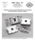
Instruction 51-1021
4-6-06
Copyright © 1995, 1996,
2002, 2005, 2006
by S&S Cycle, Inc.
All rights reserved.
Printed in the U.S.A.
S&S Cycle, Inc.
®
235 Causeway Blvd.
La Crosse, Wisconsin 54664
Phone: 608-627-1497 • Fax: 608-627-1488
Technical Service Phone: 608-627-TECH (8324)
Technical Service Email: [email protected]
Website: www.sscycle.com
Because every industry has a leader
Installation Instructions: S&S® Pinion Shafts for Big Twin
DISCLAIMER:
IMPORTANT NOTICE:
S&S parts are designed for high performance, off road, racing
applications and are intended for the very experienced rider only. The
installation of S&S parts may void or adversely effect your factory
warranty. In addition such installation and use may violate certain
federal, state, and local laws, rules and ordinances as well as other laws
when used on motor vehicles used on public highways, especially in
states where pollution laws may apply. Always check federal, state, and
local laws before modifying your motorcycle. It is the sole and exclusive
responsibility of the user to determine the suitability of the product for
his or her use, and the user shall assume all legal, personal injury risk and
liability and all other obligations, duties, and risks associated therewith.
Statements in this instruction sheet preceded by the following words
are of special significance.
The words Harley®, Harley-Davidson®, H-D®, Sportster®, Evolution®, and
all H-D part numbers and model designations are used in reference only.
S&S Cycle is not associated with Harley-Davidson, Inc.
SAFE INSTALLATION AND OPERATION RULES:
Before installing your new S&S part it is your responsibility to read and
follow the installation and maintenance procedures in these
instructions and follow the basic rules below for your personal safety.
● Gasoline is extremely flammable and explosive under certain
conditions and toxic when inhaled. Do not smoke. Perform installation
in a well ventilated area away from open flames or sparks.
● If motorcycle has been running, wait until engine and exhaust pipes
have cooled down to avoid getting burned before performing any
installation steps.
● Before performing any installation steps disconnect battery to
eliminate potential sparks and inadvertent engagement of starter while
working on electrical components.
● Read instructions thoroughly and carefully so all procedures are
completely understood before performing any installation steps.
Contact S&S with any questions you may have if any steps are unclear
or any abnormalities occur during installation or operation of
motorcycle with a S&S part on it.
WARNING
Means there is the possibility of injury to yourself or others.
CAUTION
Means there is the possibility of damage to the part or motorcycle.
NOTE
Other information of particular importance has been placed in italic type.
S&S recommends you take special notice of these items.
WARRANTY:
All S&S parts are guaranteed to the original purchaser to be free of
manufacturing defects in materials and workmanship for a period of
twelve (12) months from the date of purchase. Merchandise that fails
to conform to these conditions will be repaired or replaced at S&S’s
option if the parts are returned to us by the purchaser within the 12
month warranty period or within 10 days thereafter.
In the event warranty service is required, the original purchaser must
call or write S&S immediately with the problem. Some problems can be
rectified by a telephone call and need no further course of action.
A part that is suspect of being defective must not be replaced by a
Dealer without prior authorization from S&S. If it is deemed necessary
for S&S to make an evaluation to determine whether the part was
defective, a return authorization number must be obtained from S&S.
The parts must be packaged properly so as to not cause further damage
and be returned prepaid to S&S with a copy of the original invoice of
purchase and a detailed letter outlining the nature of the problem, how
the part was used and the circumstances at the time of failure. If after
an evaluation has been made by S&S and the part was found to be
defective, repair, replacement or refund will be granted.
ADDITIONAL WARRANTY PROVISIONS:
● Consult an appropriate service manual for your motorcycle for correct
disassembly and reassembly procedures for any parts that need to be
removed to facilitate installation.
(1) S&S shall have no obligation in the event an S&S part is modified by
any other person or organization.
● Use good judgement when performing installation and operating
motorcycle. Good judgement begins with a clear head. Don't let
alcohol, drugs or fatigue impair your judgement. Start installation
when you are fresh.
(2) S&S shall have no obligation if an S&S part becomes defective in
whole or in part as a result of improper installation, improper
maintenance, improper use, abnormal operation, or any other misuse
or mistreatment of the S&S part.
● Be sure all federal, state and local laws are obeyed with the
installation.
● For optimum performance and safety and to minimize potential
damage to carb or other components, use all mounting hardware that
is provided and follow all installation instructions.
(3) S&S shall not be liable for any consequential or incidental damages
resulting from the failure of an S&S part, the breach of any warranties,
the failure to deliver, delay in delivery, delivery in non-conforming
condition, or for any other breach of contract or duty between S&S and
a customer.
● Motorcycle exhaust fumes are toxic and poisonous and must not
be inhaled. Run motorcycle in a well ventilated area where fumes
can dissipate.
(4) S&S parts are designed exclusively for use in Harley-Davidson® and
other American v-twin motorcycles. S&S shall have no warranty or
liability obligation if an S&S part is used in any other application.
1
PRODUCT INFORMATION
S&S® pinion shaft kit, PN 33-2024, has been designed
as a composite replacement and is made to fit stock
Harley-Davidson® flywheels and S&S SE and L style
flywheels in 1958 to early 1981 big twin engines. It
can also be used in 1954 to 1957 engines, if
crankcases are modified. S&S PN 33-2024 shaft
effectively replaces Harley-Davidson® #24006-54A,
24006-58 and 24006-73.
*All reference to Harley-Davidson® part numbers is for
identification purposes only. We in no way are implying that any
of S&S Cycle’s products are original equipment parts or that they
are equivalent to the corresponding Harley-Davidson® part
number shown.
●
●
To use S&S pinion shaft 33-2024 in 1954 to1957 crankcases,
perform the following operations:
1. Remove pressed-in bearing race in the right crankcase.
2. Bore cast-in bearing retainer out to 2.125" to accept
larger diameter later 1958 to 1981 press-in race.
3. A shim must be fabricated to space later pressed-in
bearing race out to earlier bearing race position.
The S&S pinion shaft kit, PN 33-2027, is designed to fit
stock Harley-Davidson® flywheels from late 1981 to 1989
and S&S SL and BL style flywheels for late 1981 and later
engines. S&S PN 33-2027 replaces Harley-Davidson®
#24006-80, 24006-83 and 24006-87. S&S pinion shaft kits,
parts 33-2028 and 33-2029, are identical to 33-2027 in
design and application except they have bearing surface
diameters of +.001" and +.002" oversize respectively. S&S
Shaft 33-2028 replaces Harley-Davidson® #24020-87 and
shaft 33-2029 replaces Harley-Davidson® #24021-87.
NOTE: When using S&S 33-2027 pinion shaft in 1990 and
later engines with S&S flywheels, pre-1989 oil pump drive
gear and pinion gear must be used as stock gears for 1990
and later style, straight pinion shaft will not fit S&S shaft.
INSTALLATION PROCEDURE
1. Thoroughly clean shaft and blow air through oil holes
in both ends of shaft to insure no foreign material is
trapped in oil passageway.
2. 33-2024 only - Press brass plug in gear cover end of
shaft until it bottoms against shoulder in hole. For
engines 1954 to 1972 with side oiling gear covers, use
solid plug. For 1973 to early 1981 engines with end
oiling gear covers, use plug with 3⁄32" hole.
NOTES:
● When S&S pinion shaft 33-2024 is used in 1973 to 1981
engines with end oiling gear covers, side oiling feed
hole for 1954 to 1972 engines does not have to be
plugged. Amount of oil lost through side oil feed hole
in bearing surface of shaft is insignificant if gear cover
bushing is fit correctly to end of pinion shaft.
2
In 1954 to 1972 engines, oil is fed to connecting rods
once per revolution, through an oil hole inside of
pinion shaft bearing surface. Oil hole in pinion shaft
aligns with oil feed hole in pinion shaft bushing pressed
in gear cover. Later engines, 1973 to present, feed oil
continuously to connecting rods through a hole in end
of pinion shaft. Before proceeding, check your gear
cover to determine which of these oiling systems your
engine uses. Early engines from 1954 to 1972 which
have been converted with a special gear cover bushing
to oil connecting rods using 1973 to present style oiling
methods require brass plug with drilled oil metering
hole - follow instructions for 1973 and later engines.
If a 1972 or earlier gear cover is converted to end feed
style oiling, or if a groove is machined around bearing
surface of pinion shaft to allow oil to feed
continuously, low oil pressure will result unless
crankcase and oil pump are also updated to 1973 and
later oiling system.
CAUTION
●
●
Low oil pressure due to use of 1973 and later style
end oiling pinion shaft in 1972 and earlier engines
may cause overheating, premature wear, and
damage to engine components.
Installing solid end plug in 1973 and later engines will
result in insufficient oil flow to connecting rods,
causing premature wear and damage to connecting
rod bearings and other internal engine components.
3. Inspect key ways and oil holes in flywheels for burrs.
Remove burrs if necessary.
NOTE: S&S does not recommend lapping tapers to remove
burrs. This practice tends to distort the taper by removing
material unevenly around the circumference. This makes
flywheels difficult if not impossible to true. In addition the
lapping process work hardens the surface of the taper. The
resultant hard surface makes it very difficult to pull shaft
into taper. Lapped flywheel tapers are also very difficult to
resurface if repairs are ever needed.
4. Check keys in key ways of shaft. Keys should be light
hand press fit in key ways. If key is too tight in key
way, sand side of key with fine sand paper on a metal
plate or other flat surface. Do not hammer key into
key way.
CAUTION
Hammering tight key into key way may result in
irreparable damage to shaft.
5. With key in shaft, insert into respective tapered hole in
flywheel and check to see that key does not bottom in
key way of flywheel taper. If key bottoms out, file or
sand flat side of key, not rounded side, until shaft with
key in place fits in flywheel without bottoming out.
6. Assemble flywheel and shaft. Use stock factory
torque specifications (140 to 170 ft-Ibs.) in stock, cast
iron flywheels. For S&S® forged steel flywheels
tighten nut to 275 to 300 ft-lbs. S&S® recommends
that green Loctite® (RC609) or similar thread locking
product be used on taper of shaft, threads of shaft,
and face of nut.
7. Blow air through connecting rod oil feed hole in end
of pinion shaft after flywheel, crankpin and pinion
shaft have been assembled to insure that
passageway is open.
CAUTION
Restricted or blocked oil passage may result in
insufficient oil flow, and cause premature wear and
damage to internal engine components.
8. Finish assembling and truing flywheels.
9. Select correct size main bearings per Harley-Davidson®
factory procedures. Consult appropriate HarleyDavidson® manual for style of bearings used.
10. Install main bearings on pinion shaft.
●
Picture 2
There are three types of pinion main bearings which
may be used with S&S 33-2024 and 33-2027 pinion
shafts. Picture 3 shows the 1958 to 1986 style bearings
which consist of two open ended steel cages and drop
in roller bearings. The 1987 to 1993 style (FAG)
bearings consist of two stamped steel cages with roller
bearings installed. See Picture 4.
NOTES:
● There are two styles of flywheels which will accept the
S&S 33-2027 pinion shaft. Stock 1981 to 1986 style
flywheels are machined with a small diameter
shoulder around the pinion shaft taper to accept a
main bearing thrust washer. See Picture 1. Stock 1987
to 1989 and all current production S&S flywheels for
late 1981 and later engines, are machined with a large
diameter shoulder around the pinion shaft taper. This
shoulder is designed to eliminate the main bearing
thrust washer previously used. See Picture 2.
Picture 3
Picture 1
Picture 4
3
●
Bearings from 1994-’99 consist of one stamped
steel cage with a single seat of rollers installed.
See Picture 5.
2. 1981- 1986 stock flywheels and S&S pinion
shaft 33-2027 - two .070" thrust washers and
one .050" thrust washers are normally used.
Typical washer and bearing arrangement .070" washer against flywheel, bearings, .070"
washer, .070" or .050" washer, and snap ring.
See Figure 2.
.070"
.050"
.070"
Thrust Thrust Thrust
Washer Washer Washer
Picture 5
●
●
The combinations of thrust washers and bearings
shown in this instruction sheet are typical for most
installations. Individual circumstances may, however,
require that engine builder space bearings in a
different manner. Engine builder must insure that
bearing assembly rotates freely on pinion shaft and
that rollers are positioned so they are entirely
supported by the bearing race.
There is no specification for pinion bearing assembly
end play. A good rule of thumb is that if an additional
thrust washer can be installed and bearings can still
rotate freely, and are still supported by race, install it.
If not, leave it out.
A. 1954-1986 bearings
1. 1954 to early 1981 flywheels or S&S® SE or L
style flywheels, and S&S pinion shaft 33-2024 Two .070" thrust washers are normally used.
Typical washer and bearing arrangement .070" washer against flywheel, bearings, .070"
washer, and snap ring. See Figure 1.
.070"
Thrust
Washer
Figure 2
3. 1987 to 1989 big twin flywheels or S&S SL or
BL flywheels for 1981 and later, and S&S
pinion shaft 33-2027—one .070" thrust
washer and one .050" thrust washer are
normally used. Typical washer and bearing
arrangement— .050" washer against
flywheel, bearings, .070" washer, and snap
ring. See Figure 3.
.050"
Thrust
Washer
.070"
Thrust
Washer
.070"
Thrust
Washer
Figure 3
#33-2024 pinion shaft
1954 - 1981 style flywheel
1958 - 1986 style bearings
Figure 1
4
NOTE : It may be necessary to install bearing cages so that
open side faces flywheel in order to position rollers entirely
on the bearing race.
B. 1987 to 1993 big twin bearings
1. 1954 to early 1981 stock flywheels or S&S® SE or
L style flywheels and S&S pinion shaft 33-2024.
No thrust washers are normally used. Typical
bearing arrangement - bearings against
flywheel and snap ring. See Figure 4.
Figure 4
2. 1981 to 1986 big twin flywheels and S&S pinion
shaft 33-2027—extra .070" main bearing thrust
washer supplied in kit is normally used. Typical
washer and bearing arrangement - .070"
washer against flywheel, bearings, and snap
ring. See Figure 5.
.070"
Thrust
Washer
3. 1987 to 1989 big twin or S&S SL or BL style
flywheels for 1981 and later, and S&S pinion
shaft 33-2027 - No thrust washers are normally
used. Typical arrangement - bearings against
flywheel, and snap ring directly against
bearing. See Figure 6.
Figure 6
C. 1994 and later single roller style bearings
NOTE: Late style larger diameter bearing retaining clip S&S
PN 31-4021 or Harley-Davidson® H-D 11177A must be used
with late style 1994 and later single roller pinion bearings.
Earlier style smaller diameter retaining clip may not
sufficiently contact late style bearing cage to safely hold
bearing cage in place. Refer to Harley-Davidson® Service
Bulletin M-1042, 4-19-94. S&S recommends that late style
retaining clip be used with all types of pinion bearings.
CAUTION
Use of earlier style retaining clip with late style single
roller bearing may result in bearing failure and serious
engine damage.
Figure 5
5
1. 1954 to early 1981 big twin or S&S® SE or L
style flywheels and 33-2024 - No thrust
washers are normally used. Typical bearing
arrangement - bearings against flywheel and
snap ring. See Figure 7.
3. 1987 to1989 big twin or S&S SL or BL flywheels
for 1981 and later, and S&S pinion shaft 332027 - No thrust washers are normally used.
Typical arrangement - Bearing cage against
flywheel, and snap ring directly against
bearing cage. See Figure 9.
Snap Ring
Flywheel
Collar
Figure 7
Bearings
#33-2027 Pinion Shaft
1987 And Later Style Flywheels
1994 And Later Style Bearings
Figure 9
2. 1981 to 1986 big twin flywheels - Two .050"
thrust washers are normally used. Typical
arrangement - .050" washer, bearing cage,
050" washer, and snap ring. See Figure 8.
.050"
Thrust
Washer
.050"
Thrust
Washer
Figure 8
11. Install flywheel assembly in driveside crankcase.
Temporarily install camside crankcase. Check to be
sure pinion bearing rollers are fully supported by
bearing race. Adjust bearing spacing as needed.
NOTES:
● Final placement of flywheel thrust washers is
determined by position of main bearings in main
bearing race. Main bearings should be spaced so
rollers are completely supported by race surface.
● Thin thrust washers placed between flywheel and
bearing cage will sometimes drop between flywheel
collar and bearing surface of pinion shaft. A slightly
thicker thrust washer will usually solve this problem.
Also, thrust washers normally have a larger inside
chamfer on one side of washer than on other side.
Placing smaller chamfer toward bearing cage will help
minimize this problem. Thrust washers of various
thickness can be obtained from local bearing houses.
Custom thickness thrust washers can be made by
surface grinding a thicker thrust washer.
12. Final assemble crankcases.
13. Install oil pump drive gear, spacer, and pinion gear on
pinion shaft. Apply Loctite® to threads of pinion gear
nut and torque to 45 ft-lb.
6
NOTES:
● Oil pump drive gear spacer will not completely fill gap
between oil pump drive gear and pinion gear. A gap
of up to .125" may exist, and is normal. Function of
spacer is to prevent pinion shaft oil pump drive gear
from disengaging from oil pump drive shaft gear if
engine is turned backward. During normal operation,
oil pump drive gear is pulled toward pinion shaft
bearing boss.
● Be sure oil pump drive gear is installed with chamfered
side toward pinion shaft bearing boss. See Figure 10.
Right
Chamfer toward pinion
shaft bearing boss
CAUTION
If oil pump drive gear is installed with sharp edge
against radius on pinion shaft bearing boss, sharp edge
may nick radius. This can result in a stress riser that
may cause shaft to break. See Figure 10.
14. Install cam, breather gear, and gear cover according to
Harley-Davidson® factory procedure.
NOTE: Gear cover should slide into place with little or no
resistance. If gear cover will not slide on easily, cause of
resistance must be determined and corrected. Under no
circumstances should cover be forced into place.
CAUTION
Forcing gear cover on may subject pinion shaft to
unwarranted side loading and flexing which during
operation can cause shaft to fatigue and break.
Wrong
Sharp edge toward pinion
shaft bearing boss
Figure 10
7
Because every industry has a leader