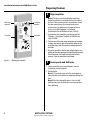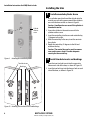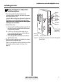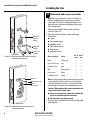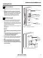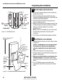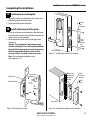
1
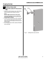
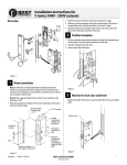
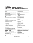
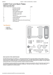
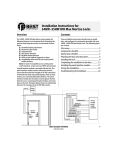
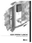
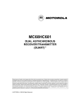
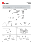
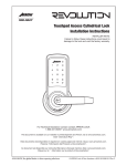
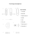
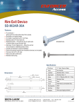
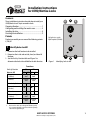
Installation Instructions
for 45HQ Mortise Locks
Contents
A
B
These installation instructions describe how to install your
45HQ Mortise Lock. Topics covered include:
Preparing the door ......................................................... 1
Configuring and installing the mortise case................. 3
Installing the trim............................................................ 4
Finishing the installation................................................ 9
C
F
Patents
Products covered by one or more of the following patents:
6,720,861
1
B
For hole sizes, see the
Q06 Template (T82606).
G
Identify holes to drill
H
1 Determine the lock function to be installed.
2 Determine the inside and outside, hand, and bevel of
the door.
3 See the Holes by Function table and Figure 1 to
determine the holes to be drilled for the lock function.
G
D
Figure 1
A
D
Identifying holes to drill
Functions
Holes by Function
Holes to drill
A Forged trim
(2 holes)†
B Harness†
DV
TV
I/S O/S
Through
door
Through
door
I/S O/S
Through
door
Through
door
D Sensor & motor wire
(2 holes)
■
H Lever††
†
‡
■
■
F Thumb turn
G Trim mounting
(2 holes)‡
■
■
C Standard cylinder
Through
door
Through
door
Through
door
Through
door
Determine trim holes based on trim type.
Because these holes pass through the mortise pocket,
it is recommended that each hole be drilled separately
rather than straight through.
BEST ACCESS SYSTEMS
a Division of Stanley Security Solutions, Inc.
1
Installation Instructions for 45HQ Mortise Locks
Preparing the door
2
Door edge
template
Installation
template
Centerline
Centerline
Figure 2
Aligning the templates
Align templates
Note: If the door is a fabricated hollow metal door,
determine whether it is properly reinforced to support
the lock. If door reinforcement is not adequate, consult
the door manufacturer for information on proper
reinforcement. For dimensions for preparing metal
doors, see the Q03 Template—Installation
Specifications for 45HQ Mortise Locks (T82603).
1 Separate the four templates provided on the Q06
Template—Installation Template for 45HQ Mortise
Locks (T82606).
2 Position one of the door edge templates on the door,
making sure that the lock case mortise shown on the
template aligns with the mortise pocket prepared in
the door.
3 Using the centerlines on the door edge template as a
guide, position the appropriate door template on each
side of the door. You need to take the bevel into
account. Tape the templates to the door.
3
Center punch and drill holes
1 Center punch the necessary drill points. See the
instructions on the template.
2 Drill the holes.
Note 1: To locate the center of a hole on the opposite
side of the door, drill a pilot hole completely through the
door.
Note 2: For holes through the door, it is best to drill
halfway from each side of the door to prevent the door
from splintering.
2
BEST ACCESS SYSTEMS
a Division of Stanley Security Solutions, Inc.
Installation Instructions for 45HQ Mortise Locks
Preparing the door
4
Install door status switch
(optional for deadbolt TV function locks
only)
Door
status
switch
Shield
1 Position the shield on the door status switch with the
notch facing downwards (towards the mortise
pocket).
Caution: Make sure the wires are not routed
across any sharp edges or over any surface that
could damage its sleeving.
2 Feed the wires for the door status switch into the door
status switch hole and through the channel into the
mortise cavity and out through one of the sensor and
motor wire holes.
3 Press fit the door status switch assembly into the door
status switch hole.
Figure 3
BEST ACCESS SYSTEMS
a Division of Stanley Security Solutions, Inc.
Installing the door status switch for
3
Installation Instructions for 45HQ Mortise Locks
Configuring & installing the mortise case
5
Note: If a function specific mortise case was ordered,
some steps for configuring the case have already been
performed at the factory.
1 Determine whether you need to rotate the latchbolt to
match the handing of the door.
Note: The angled surface of the latchbolt must contact
the strike when the door closes.
2 If you need to rotate the latchbolt, insert a flat blade
screwdriver into the latch access point approximately
1/2″ into the case and press to extend the latch out of
the case. See Figure 4.
3 Rotate the latchbolt 190 degrees (slightly past 180
degrees) and allow it to retract into the case.
Latch access point
Figure 4
Rotate latchbolt (if necessary)
Rotating the latchbolt
6
Position hub toggles (if necessary)
1 Check whether the hub toggles are in the proper
position for the lock. See the table below and Figure 5.
Hub toggle positions
Hub toggle
Figure 5
4
Positioning hub toggles
Hub toggle
Function
Hub toggle positions
DV, TV
Inside down (always unlocked) &
outside up (lockable)
Note: For LH & LHRB doors, the inside is the back side of
the case and the outside is the cover side of the case.
For RH & RHRB doors, the inside is the cover side of the
case and the outside is the back side of the case. The
cover is mounted to the case with four screws.
2 To change the position of a hub toggle, remove the
toggle screw, move the toggle into the desired
position, and re-tighten the screw.
BEST ACCESS SYSTEMS
a Division of Stanley Security Solutions, Inc.
Installation Instructions for 45HQ Mortise Locks
Installing the trim
7
Mortise cavity
Install mortise case
1 Drill the holes for the case mounting screws.
2 Insert the mortise case into the mortise cavity, while
feeding the sensor and motor wires into the mortise
cavity and out the two sensor & motor wire holes to
the inside of the door as shown in Figure 6.
Note: The armored front of the mortise case self-adjusts
to the door bevel.
3 Secure the mortise case with the case mounting
screws.
8
Mortise case
Case
mounting
screws
Install trim mounting plates
1 Insert the outside trim mounting plate through the
door and mortise case.
2 Position the inside trim mounting plate opposite the
outside trim mounting plate and screw them securely
in place.
Caution: Do not overtighten the trim mounting
plate screws. Overtightening may damage the
locking mechanism.
3 By temporarily installing a lever, test the lock to make
sure that it doesn’t bind.
Sensor & motor
wire holes
Figure 6
Sensor wires
and motor
wires
Installing the mortise case (inside of door)
Outside
mounting
plate
Inside
mounting
plate
Figure 7
BEST ACCESS SYSTEMS
a Division of Stanley Security Solutions, Inc.
Installing the trim mounting plates
5
Installation Instructions for 45HQ Mortise Locks
Installing the trim
9
Cylinder
retainer
screw
Figure 8
Installing the concealed cylinder
Install concealed cylinder & core
1 Use a cylinder wrench to thread the cylinder into the
mortise case so that the groove around the cylinder is
even with the door surface as shown in Figure 8.
Caution: A malfunction can occur if the cylinder is
threaded in too far.
2 Secure the cylinder in the mortise case with the
cylinder retainer screw.
3 Insert the control key into the core and rotate the key
15 degrees to the right.
4 With the control key in the core, insert the core into
the cylinder.
5 Rotate the control key 15 degrees to the left and
withdraw the key.
Caution: The control key can be used to remove
cores and to access doors. Provide adequate
security for the control key.
10
Install trim hole inserts and bushings
1 Insert the two trim hole inserts into the upper trim
hole on each side of the door, as shown in Figure 10.
2 Insert the two bushings into the harness hole on each
side of the door, as shown in Figure 10.
Trim hole inserts
Bushings
Figure 10 Installing the trim hole inserts and bushings
6
BEST ACCESS SYSTEMS
a Division of Stanley Security Solutions, Inc.
Installation Instructions for 45HQ Mortise Locks
Installing the trim
11
Route wire harnesses and position
outside escutcheon
1 From the outside of the door, feed the motor
connector, battery connector, and sensor connectors
through the harness hole.
Caution: When routing the connectors, make sure
the harnesses are not routed across any sharp
edges or over any surface that could damage their
sleeving or wire insulation.
2 Perform these steps:
a Firmly press the outside escutcheon in position on
the door. The core should be flush with the outer
surface of the escutcheon.
b If necessary, adjust the cylinder depth plus or
minus one turn so that the core is flush with the
outer surface of the escutcheon.
c Secure the cylinder in the mortise case with the
cylinder clamp screw.
3 Rest the outside escutcheon on the door by inserting
the trim studs into the trim holes.
Tip: You can temporarily install the outside lever to hold
the outside escutcheon in place. See Figure 15 on
page 10.
Harness
hole
Sensor
connectors
Battery
connector
Motor
connector
Antenna
Cylinder clamp
screw (inside
mortise case)
Outside
escutcheon
Outside of door
Figure 11 Feeding the wire harness connectors through the
harness hole
BEST ACCESS SYSTEMS
a Division of Stanley Security Solutions, Inc.
7
Installation Instructions for 45HQ Mortise Locks
Installing the trim
12
Wire tie &
wire tie
holder
Motor connection
Inside of door
Sensor connections
Figure 12a Using the wire tie and wire tie holder to
manage the connections
Antenna
Battery connector
Sensor
connections
Inside of door
Make motor and sensor connections
Note: We suggest that you use a wire tie and wire tie
holder to help manage the wire harnesses and their
connections. This will also help keep the harnesses in
place inside the escutcheon and help prevent the wires
from being pinched.
1 Affix the wire tie holder and insert the wire tie as
shown in Figure 12a.
2 From the inside of the door, make the following
connections:
■ motor
■ key override sensor
■ deadbolt sensor
■ RQE (request to exit)
■ door sensing
■ latchbolt sensing
Wire connection
No. of No. of
wires pins
Motor
Yellow-gray
2
2
Key override sensor
Gray
2
3
Deadbolt sensor
Blue
2
3
RQE
Orange-brown
2
3
Door sensing
White
2
2
Latchbolt sensing
Purple
2
2
Note: It is physically possible to connect the key override
sensor connector from the mortise case to the battery
connector from the wire harness. To avoid this mistake,
connect only the connectors with matching wire colors.
Caution: When making the motor connection and
sensor connections, make sure:
■ there are no loose wire connections where the
wires are inserted into the connectors
■ the connectors are firmly mated
3 Push any excess wire back into the holes to help avoid
pinching wires.
Figure 12b Making the motor connection and
sensor connections
8
Colors
BEST ACCESS SYSTEMS
a Division of Stanley Security Solutions, Inc.
Installation Instructions for 45HQ Mortise Locks
Installing the trim
13
Secure escutcheons
1 Position the inside and outside escutcheons on the
door.
2 Making sure that the escutcheons do not pinch
the wires, secure the escutcheons to the door. Do not
tighten the screws completely. Use the combination
mounting screw in the upper trim hole and the
standard mounting screw in the lower trim hole.
Inside escutcheon
Combination
mounting screw
Antenna wire
14
Install battery pack
Battery
connection
1 Connect the battery pack to the battery connector on
the wire harness inside the battery compartment.
When the battery pack is connected for the first time, the
lock will go through a self check and you should see eight
red, then green alternating flashes.
Note: The battery connection has 3 wires and 3 pins. The
wire colors are:
■ red (2)
■ black
Caution: When connecting the battery pack, make
sure:
■ there are no loose wire connections where the
wires are inserted into the connectors
■ the connectors are firmly mated.
Standard
mounting screw
Inside of door
Figure 13 Securing the escutcheons
2 Place the battery pack inside the battery compartment
so that the foam will face the battery compartment
door.
3 When routing the battery wires, make sure the
wires are not routed across any sharp edges or
over any surface that could damage their sleeving
or wire insulation.
Inside
escutcheon
Antenna wire
Battery pack
Figure 14 Connecting the battery pack
BEST ACCESS SYSTEMS
a Division of Stanley Security Solutions, Inc.
9
Installation Instructions for 45HQ Mortise Locks
Completing the installation
15
Antenna
wire
Location
of set
screw
Outside of door
Spindles
Inside of door
Figure 15 Installing the levers
1 Unscrew the inside spindle one full turn to allow the
spindles to turn freely.
2 With the handle pointing toward the door hinges,
insert the outside lever and spindles assembly into the
lock from the outside of the door.
3 Slide the inside lever onto the inside spindle and
secure it with the set screw.
4 Making sure that the core is positioned properly in the
outside escutcheon and the escutcheons are aligned
properly on the door, tighten the escutcheon
mounting screws.
Note: If a core is not available, you can use the cylinder
wrench to help you align the core opening in the
escutcheon.
5 Turn the levers to check that they operate smoothly.
16
Battery
Battery compartment
Battery cover/
antenna
Store excess
antenna
wires above
battery
compartment
Connect
antenna
wires
Tabs
Antenna
wire
loop
Install inside and outside levers
Install battery cover/antenna
1 Carefully shape the antenna wire with a loop as shown
in Figure 16.
Caution: Carefully bend, but do not twist or kink
the antenna wire. Doing so may significantly
reduce or completely interrupt signal transmission.
2 Connect the antenna to its mating connector.
3 Route the antenna wire down below the battery compartment. See Figure 16.
4 Making sure that the battery cover/antenna does
not pinch any wires, insert the tabs of the battery
cover/antenna into its mating slots and swing the door
closed.
6 Use a T15 TORX bit driver to secure the battery
compartment door with the security screw. Tighten
firmly.
Figure 16 Installing the battery compartment door
10
BEST ACCESS SYSTEMS
a Division of Stanley Security Solutions, Inc.
Installation Instructions for 45HQ Mortise Locks
Completing the installation
17
Install mortise case faceplate
1 Secure the mortise case faceplate to the mortise case
with the faceplate mounting screws.
2 Check the lock for proper operation.
18
Mortise
case
faceplate
Install strike box and strike plate
1 Insert the strike box into the mortise in the door jamb.
Place the strike plate over the strike box and secure the
strike with the screws provided.
2 Check the position of the auxiliary bolt against the
strike plate.
Caution: The auxiliary bolt must make contact
with the strike plate. The auxiliary bolt deadlocks
the latchbolt and prevents someone from forcing
the latch open when the door is closed. If the
incorrect strike is installed, a lock-in can occur.
Note: The recommended gap between the
door and jamb is 1/8″ .
Faceplate
mounting
screws
Outside of door
Figure 17 Installing the mortise case faceplate
Make sure to
position the
magnet at
the top.
Strike plate
Strike
box with
magnet
Strike
plate
Auxiliary bolt
Door jamb
Figure 18b Positioning the strike
Figure 18a Installing the strike box and strike plate
BEST ACCESS SYSTEMS
a Division of Stanley Security Solutions, Inc.
11
Installation Instructions for 45HQ Mortise Locks
Testing the lock
19
Test lock
For 45HQ Locks with keypad
To test the lock for proper operation before the lock is
programmed, follow these instructions:
1 Press 1234.
2 Press #.
The green light flashes and the locking mechanism
unlocks.
3 Turn the lever and open the door.
For all other locks:
To test the lock for proper operation before the lock is
programmed, use the temporary operator card that came
with the lock. This card is for temporary use only. After
permanent cards have been programmed for the lock, the
temporary card should be deleted.
1 Use the temporary operator card to activate the lock.
Note: If the lock has a proximity card reader, it may have
already been activated by the presence of an object near
the card reader.
2 Use the temporary operator card to access the lock.
The green light flashes and the locking mechanism
unlocks.
3 Turn the lever and open the door.
If the mechanism doesn’t unlock, refer to the
following table. For additional troubleshooting
instructions, see the Service Manual.
LEDs
Sounder
Single
red flash
—
You should
Use the card at a moderate speed.
Red
flashes
3 short
tones
Use the temporary operator card
provided with the lock.
Green
flashes
—
Check the motor connection.
—
—
Check the battery connection.
For all locks
Insert and turn the key to unlatch the door.
For all TV function locks
4 From the inside of the door, turn the turn knob and
make sure that the deadbolt operates properly.
©2008 Stanley Security Solutions, Inc. and Stanley Logistics, Inc.
T82623/Rev A 3108931 ER-7991-12 Oct 2008
12
BEST ACCESS SYSTEMS
a Division of Stanley Security Solutions, Inc.