1
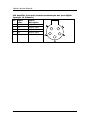
Service Guide MAN003 Service Guide MAN003 Taugagreining hf Armuli 10 108 Reykjavík, Iceland Tel: +354 580 7500 Fax: +354 580 7501 www.nervus.is [email protected] Using this manual The Nervus range of Multimedia EEG systems has been designed and manufactured by Taugagreining hf, an Icelandic company that has always had an enviable reputation for innovation and quality of its products. Taugagreining hf has been certified by SEMKO as an approved medical devices manufacturer as meeting the requirements of the Medical Devices Directive (93/42/EEC) Taugagreining hf quality management system has been certified by SEMKO-DEKRA to comply with ISO 9001:2000. The Nervus range of EEG systems has been independently tested and successfully approved to the following medical safety standards: EN 60601-1, EN 60601-1-2, IEC 601-1, IEC 601-1-2, UL 2601-1, CAN/CSA-C22.2 No. 601.1-M90, JIS T 1001/JIS T 1002 or JIS T 0601-1. 0413 The Nervus range of EEG systems is CE Marked in accordance with the European Council Directive 93/42/EEC concerning medical devices. Caution: in the USA federal law restricts this device to sale by, or on the order of, a physician iii Nervus Service Manual Copyright All rights reserved. This manual contains proprietary information which is protected by copyright and may not be copied in whole or in part except with the prior written permission of Taugagreining hf. The copyright and the foregoing restrictions on the copyright use extend to all media in which this information may be preserved. This copy of the User Manual shall be used only in accordance with the conditions of sale of Taugagreining hf or its distributors. Taugagreining hf makes no representations or warranties of any kind whatsoever with respect to this document. Taugagreining hf disclaims all liabilities for loss or damage arising out of the possession, sale or use of this document. Nervus® is a registered trademark of Taugagreining hf. Medelec® is a registered trademark of Oxford Instruments Medical. TECA® is a registered trademark of Oxford Instruments Medical. Microsoft® Windows®, Windows NT®, Windows XP® and Office® are registered trademarks of Microsoft Corporation. Intel Pentium® is a registered trademark of INTEL Corporation. All other trademarks and product names are the property of their relevant owners. Taugagreining hf Ármúli 10 108 Reykjavik Iceland Tel: +354 580 7500 Fax: +354 580 7501 www.nervus.is iv Using this manual Contents Using this manual................................................................1 1. 2. 3. Technical overview .....................................................3 1.1 Introduction...................................................................................... 3 1.2 Outline of Nervus data acquisition system..................................... 3 1.3 Power supplies.................................................................................. 4 1.4 USB interface card............................................................................ 8 1.5 IBox interface ................................................................................. 10 1.6 Nervus M40 amplifier .................................................................... 11 1.7 Nervus C64/C32 amplifier .............................................................. 11 1.8 Nervus U32 amplifier ..................................................................... 13 1.9 Photic stimulator ............................................................................ 13 1.10 Videum 1000+ video capture card ................................................ 14 System functional checks .........................................15 2.1 Equipment required....................................................................... 15 2.2 Setting the system up for checking .............................................. 15 2.3 Basic functionality checks .............................................................. 16 2.4 Amplifier checks ............................................................................. 17 2.5 Recording checks............................................................................ 22 2.6 Review checks................................................................................. 24 2.7 Printer checks ................................................................................. 24 2.8 Audio checks................................................................................... 25 2.9 CD-Writer checks............................................................................ 25 2.10 DVD-Writer checks ......................................................................... 25 2.11 Removing test files......................................................................... 26 Fault finding ..............................................................27 v Nervus Service Manual 4. 5. 6. 7. vi 3.1 Hardware and Windows problems ............................................... 27 3.2 Nervus applications software problems ....................................... 28 Maintenance ..............................................................33 4.1 Routine maintenance .................................................................... 33 4.2 Cleaning.......................................................................................... 33 4.3 Backing up data ............................................................................. 34 Servicing the Nervus.................................................35 5.1 Nervus Notebook PC ...................................................................... 35 5.2 Nervus Desktop PC ......................................................................... 36 5.3 Nervus amplifiers and IBox............................................................ 36 5.4 Nervus medical power supply ....................................................... 36 Technical information..... Error! Bookmark not defined. 6.1 Technical Specifications ................................................................. 37 6.2 Amplifier function ......................................................................... 38 6.3 Interface connections .................................................................... 39 Index ..........................................................................43 Using this manual Using this manual Intended readers The Nervus EEG system facilitates the capture and review of electroneurophysiological data. The information contained in this Service Guide should enable a qualified electronic technician to verify the correct functioning of the equipment and to fault find to sub-assembly level. This guide is intended to be a supplement to the Nervus User Manual. Please refer to the Nervus User Manual for information on safety, system connections and overview of the software. As the majority of the components used within the Nervus systems are surface mount technology (SMT) devices, any defective sub-assembly should be replaced as a complete item. To assist with this, fully tested replacement sub-assemblies are available from Taugagreining hf and principal distributors. As the Nervus system is designed for the Microsoft® Windows® operating system, you need to be familiar with its basic features. If necessary, refer to the appropriate manuals supplied with Windows for an explanation of the terminology used here. To resolve any queries regarding the operation of the system that cannot be resolved by consulting the User Manual or the application’s help screens, you should consult either Taugagreining hf or its authorised agent in your country, or see the contact information at the start of this manual. 1 Nervus Service Manual 2 Technical overview 1. Technical overview 1.1 Introduction This chapter describes the principal components of Nervus systems, including the amplifiers, photic stimulator, USB Interface Card and IBox. Technical specifications of the components are given in Technical information. All other boards used in the Nervus systems are OEM and you should refer to the manufacturer’s documentation for further information. 1.2 Outline of Nervus data acquisition system Patient signals are amplified, filtered, and digitised within the amplifier at a sampling rate defined by the recording protocol being used by the Nervus Recorder software. The “Raw” digitised data is transmitted across a serial link from the amplifier to an interface card in the PC. The Nervus Recorder reads the “Raw” data from the interface card and stores it to disk in a location, known as the Recarea, which is used for storing data from recordings in progress. The Recarea is located on the hard drive of the recording unit. At the same time the Nervus Recorder software processes the “Raw” data based on the recording protocol being used to derive the “Montaged” EEG data which is displayed on the screen. If the acquisition system is also configured for videometry, then the video input is converted into a digital format, displayed on the screen with the EEG data and, at the same time, stored to the Recarea alongside the “Raw” EEG data but moved to Workarea during the recording. When the data acquisition is finished, the recorded EEG data (and video data if present), is “registered” (moved) to a unique sub-folder in a centralised location known as the Workarea, which is used for storing data from completed recordings. The Workarea, like the Recarea, can either be located on the hard drive of the recording unit or, in the case of a networked system, on the hard drive of a server somewhere on the network. NOTE: If recordings are made on a networked acquisition system that has been temporarily disconnected from the network, then the recordings cannot be transferred to the central Workarea when the recording is complete. Under these circumstances recordings are stored locally until the acquisition unit is reconnected to the network at which time the system will automatically transfer any local recordings to the centralised Workarea. 3 Nervus Service Manual The EEG data (and video file) stored in the Workarea can be reviewed on the acquisition system or, in the case of a networked system, on any other Nervus system attached to the network. Several Nervus systems can simultaneously view the same EEG file, however, only one system, the one which opened it first, can edit the file. The Nervus Reader defaults to viewing the data as it was recorded, however, the data can be remontaged and displayed if required. Once the data has been reviewed/edited it can then be archived for long term storage using removable media such as CDR or DVD+RW disks. 1.3 Power supplies Mains supplies Check that the mains supply cable is fitted with a shrouded 3-pin mains connector (female) which mates with the appliance inlet at the back of the unit. Check that the free end of the mains supply cable is fitted with a suitably rated mains plug having protective earth connection. The wires are colour coded as follows: Factory-fitted (ROW) US and Canada Colour Connection Colour Connection Brown Live Black Line Blue Neutral White Neutral Green/yellow Protective earth Green or Green/yellow Protective earth The protective earth wire (green/yellow) must be connected to the protective earth conductor. Check that the protective earth conductor is connected to an external protective earth system to ensure patient safety and correct operation of the unit. This protection is automatic in three-wire mains systems if the mains plug has been correctly wired. Connecting the systems For the Nervus Desktop based Acquisition systems, the shrouded female socket of the mains supply cable mates with the male connector on the isolation transformer. Separate mains leads fitted with moulded male and female connectors are then used to connect the PC, monitor etc. to the isolated mains supply from the isolation transformer. 4 Technical overview For Nervus Notebook based systems, when there is no isolation transformer, the mains cable is connected directly to the medical power supply. When an isolation transformer is supplied, the shrouded female socket of the mains supply cable mates with the male connector on the isolation transformer. Separate mains leads fitted with moulded male and female connectors are then used to connect the PC, monitor etc. to the isolated mains supply from the isolation transformer. For the Nervus Reader systems, the mains leads are connected directly to the mains supply as there are no patient connections and therefore no requirement for an isolation transformer. However a Nervus Reader system will require an isolation transformer if a MR95 is to be connected to it and to a patient at the same time. Voltage selection For Nervus Desktop systems, check the voltage settings and fuse ratings as described below. The input voltages of the Desktop PC, monitor, optional printer and photic stimulator must all be set to match the output voltage of the isolation transformer. Refer to the rating labels and relevant user manuals to check if adjustment is necessary and for information on how to carry out any required adjustments. For the Nervus Notebook systems the medical power supply used is autoranging. However the voltage setting of the Photic must be checked (see Photic supply voltage selection on page 5). For the Notebook PC, check the rating label and its user manual to see if any adjustment is required. PC Desktop supply voltage selection Refer to the user manual supplied with the PC Desktop. PC Monitor supply voltage selection Refer to the user manual supplied with the PC Monitor. Photic supply voltage selection 1. Check that the ac mains supply voltage indicated by the slide switch next to the mains inlet connector at the rear of the photic is correct for the local ac mains supply. 2. If it is not correct, it must be changed before connecting to the mains supply. The slide switch has two positions, 115V and 230V and the actuator should be set so that it is adjacent to the required voltage setting. 5 Nervus Service Manual The mains selector switch should never be operated when the equipment is connected to the mains supply. See the printed value on the end panel of the photic for the fuse rating. ISO1000 supply voltage selection The ISO1000 isolating transformer is user adjustable to either 100-120V or 200-240V operation. Refer to the instructions supplied for details on selecting the supply voltage. Before connecting it to the mains supply and connecting the PC etc. to its isolated outputs, ensure that both the input and output supply voltages are set to match the mains supply voltage. If they are not correctly set, they must be changed before connecting the isolation transformer to the mains supply. ISB-060W supply voltage selection The ISB-060W isolating transformer is configurable for either 115V or 230V operation. Refer to the instructions supplied for details on selecting the supply voltage. Before connecting it to the mains supply and connecting the PC etc. to its isolated outputs, ensure that both the input and output supply voltages are set to match the mains supply voltage. If they are not correctly set, they must be changed before connecting the isolation transformer to the mains supply. Mains fuses PCs and PC peripherals The internal PC power supplies for the Nervus Desktop, Notebook PCs and the monitors have internal mains fuses. These are not user accessible. Should a failure be suspected seek advice from the service organisation of the manufacturer of the device. ISO1000 The ISO1000 isolating transformer has two mains fuses F1 and F2 located in the mains inlet connector. They must be of the correct type and rating as stated on the label next to the mains inlet connector. The isolating transformer mains fuse values must correspond to those required by the local mains supply voltage. The required fuse values are shown in the following table: 6 Technical overview Mains voltage 100-120V Fuse rating T10A H 250V 200-240V T6.3A H 250V Fuses are HIGH BREAKING CAPACITY type If either fuse in the isolating transformer fails shortly after replacement, a fault is indicated and a qualified electronic technician should be consulted to trace and repair the fault. ISB-060W The ISB-060W isolating transformer has two mains fuses located in the mains inlet connector. They must be of the correct type and rating as stated on the label next to the mains inlet connector. The isolating transformer mains fuse values must correspond to those required by the local mains supply voltage. The required fuse values are shown in the following table: Mains voltage Fuse rating 115V T6.3A L 250V 230V T3.15A L 250V Fuses are LOW BREAKING CAPACITY type Photic The photic has two mains fuses F1 and F2 located near the mains inlet connector. They must be of the correct type and rating as stated on the label next to the mains inlet connector. The fuses may be removed by inserting a wide flat bladed screwdriver or thin coin in the slot and turning it anti-clockwise 90° until the spring-loaded fuse-holder pops out. The two fuses have the same rating and it is the same for all supply voltages: Mains voltage Fuse rating 115V/230V T500mA L 250V Fuses are LOW BREAKING CAPACITY type Medical Power Supply The Medical Power Supply is used in the Nervus Notebook systems 7 Nervus Service Manual The medical power supply operates from mains inputs from 100V to 240V 47-63Hz. The maximum mains input current is 2A and it provides an isolated dc output of +15V 6A. Isolating transformers Isolating transformers are used in the Nervus systems as follows: • The Nervus ISO1000 is used in Nervus Desktop systems • The Nervus ISB-060W is used in Nervus Notebook systems that have printers, to meet patient safety requirements. All parts of the system must be powered from the outlets of the isolating transformer. However, if required, the Photic stimulator (see Photic stimulator on page 13) may be connected directly to a fixed mains socket outlet. 1.4 USB interface card All Nervus systems use the USB interface card in one way or another. In Desktop based system the interface card is plugged into a PCI slot but in Notebook based systems the card is either inside the amplifier (Nervus U32) or in the IBox. The USB interface card is fitted internally in the PC Desktop and is an interface from the Nervus amplifier and photic to the USB connector of the PC. It is plugged into the PC’s PCI bus and draws 12V dc. The Desktop PC must be powered via an isolating transformer from the mains. Connecting the USB card Card to amplifier / photic: The Nervus amplifier and the photic are connected to the USB interface card by the splitter cable. Card to PC: The card has a short looping cable connecting it to the USB input of the PC. This cable is the only data link with the PC, also providing control signals and +5V dc to the card. The +5V dc is supplied to a voltage converter that provides +5V dc and -5V dc to the circuits on the card. 8 Technical overview There is also an SMPSU that supplies the power for the Nervus amplifier. The output voltage of the SMPSU can be set to either 5.6V or 6.3V. Jumper link HDR1 controls the selection of the output voltage: with the link fitted the output is 5.6V and with no link fitted the output is 6.3V. The higher voltage should be selected if the card is to be fitted to a 128 channel system or if a Nervus amplifier is to be used with a long cable run. Input / output connectors 26 way auxiliary non-isolated Input/output connector: Four auxiliary analogue input channels These signals must be referenced to non-isolated ground. Auxiliary digital inputs / outputs Can typically be used to trigger from or to an external device such as a photic stimulator. Can be put to a variety of uses, for example the signal from a SaO2 monitor, patient movement or light sensor. The 032D014 cable assembly, a 26 way D type high-density plug to 6 BNC plugs, can be used to interface with these inputs and outputs. 9 Nervus Service Manual 1.5 IBox interface An IBox is essentially a USB Interface card inside a box to make it self contained. The IBox interface must be powered from the special medical power supply. This supply may be directly connected to a fixed mains socket outlet and supplies 15Vdc to the IBox. Connecting the IBox IBox to PC: The IBox has a cable connecting it to the USB input of the PC. This cable is the only data link with the PC, also providing control signals and +5V dc to the card. The +5V dc is supplied to a voltage converter that provides +5V dc and -5V dc to the circuits on the card. There is also an SMPSU that supplies the power for the Nervus amplifier. The output voltage of the SMPSU can be set to either 5.6V or 6.3V. Jumper link HDR1 controls the selection of the output voltage: with the link fitted the output is 5.6V and with no link fitted the output is 6.3V. The IBox must be configured ONLY for 5.6V output. IBox to amplifier / photic: The Nervus amplifier and the photic are connected to the IBox by the splitter cable. Input / output connectors See USB Interface Card 10 Technical overview 1.6 Nervus M40 amplifier The patient connectors are as follows: Patient connections to the EEG amplifier system 52 touchproof connectors: 36 connectors configured as 32 EEG channel with 2 EEG Reference and 2 EEG Neutral inputs 16 connectors configured as 8 bi-polar channels Event marker Can be attached via a 3.5mm socket to input patient events. Pulse and Respiration transducers Can be attached via 3.5mm sockets. Impedance check Switches for selecting the Impedance check test and for selecting the Impedance check level. LEDs The results of the Impedance Check are returned from the PC via the amplifier board and LEDs illuminate to give a pass / fail indication against the set level. 1.7 When one of these transducers is attached to the board, circuitry on the board automatically disconnects the polygraphy inputs for the relevant channel. For example, if the Resp 1 transducer is connected, the second Polygraphy channel input is automatically disconnected from the amplifier. Nervus C64/C32 amplifier The Nervus C64/C32 amplifier variant has similar functionality to the Nervus M40 amplifier though it is far smaller and can easily be worn by the patient for long periods. The amplifier has 64/C32 EEG input channels with Reference and Neutral inputs. Of these 64/32 channels 32/16 can be configured as bipolar polygraphy input channels. C64 and C32 amplifier are used with LTM systems. The amplifier has the following internal boards: • Compact amplifier control board • 2 or 4 X 16 channel amplifier boards. 11 Nervus Service Manual The amplifier receives low voltage dc power from the USB Interface card, which is in the PC Desktop. Connecting the Nervus C64/C32 amplifier PC to mains: The PC Desktop must be connected to the mains via the Isolation Transformer. Amplifier to PC: The C64/C32 amplifier has a single cable connecting it to the splitter cable, which in turn connects to the USB interface card. The cable provides the RS422 data link, control signals and dc power for the amplifier. There is an optically coupled voltage converter on the compact amplifier control board. This provides the isolated +5V dc and isolated -5V dc to the power the patient amplifiers and associated control circuits. Amplifier to photic: The Nervus photic stimulator uses the other connection on the splitter lead to connect to the USB interface card. Amplifier to patient electrodes: Signals from the patient electrodes are connected to the touch proof connector block. This connector block has a set of multi-way connectors and can be unplugged from the compact amplifier if required. Patient signals from the connector block are passed to the inputs of the four 16 channel mini amplifier boards. These amplifiers have a gain of 500 with some Low frequency band pass filtering. The amplified signal is then digitised by the 22-bit ADC. There is one ADC per channel. Other input / output connectors Multi-way connector Supports other input signals. These can be passed through the amplifier control board, to become part of the signal sent the USB interface card then the PC’s USB port. 3.5mm jack socket Supports Patient Event button. This event signal is passed through the interface board to become part of the signal sent to the PC’s USB port. Auxiliary digital inputs and outputs Can typically be used to trigger from or to an external device such as a photic stimulator. 12 Technical overview 1.8 Nervus U32 amplifier The Nervus U32 amplifier places all the functionality of an EEG amplifier and USB interface board in the same housing and is therefore well suited for use with Notebooks. The amplifier has 32 EEG input channels with Reference and Neutral inputs, plus 8 bipolar polygraphy input channels. The amplifier has the following internal boards: • USB amplifier control board • 2 X 16 channel amplifier boards • USB interface board. The amplifier must be powered from the medical power supply. There is an isolated voltage converter mounted on the amplifier control board. This provides the isolated +5V dc and isolated -5V dc to power the patient amplifiers and associated control circuits. Connecting the Nervus U32 amplifier Amplifier to PC: The Nervus U32 amplifier has a cable connecting it to the USB input of the PC. This cable is the only data link with the PC, also providing control signals and +5V dc. The +5V dc powers the USB interface control circuitry in the amplifier. Amplifier to photic: The Nervus photic has a dedicated connector on the Nervus 32 amplifier, so there is no need for a splitter lead with this system. Amplifier to patient electrodes: Signals from the patient electrodes are connected to the touchproof or the headcap connector inputs on the amplifier control board. The signals are then passed to the amplifier boards. These amplifiers have a gain of 500 with some low-frequency band pass filtering. The amplified signal is then digitised by the 22 bit ADC. There is one ADC per channel. 1.9 Photic stimulator The mains settings of the Nervus photic must be set to match the local mains supply, or serious damage may result. The photic stimulator is normally powered from an isolating transformer, however, if required it may be connected directly to a separate mains socket outlet. The photic interfaces with Nervus systems via a single 15 way D-sub connector on the rear panel. The interface utilises differential line drivers 13 Nervus Service Manual and receivers to ensure reliable data transfer between the photic and the system. The photic stimulator contains two circuit boards: Micro-controller The micro-controller board provides the communication and control interfaces that allow the Nervus system to control the operation of the photic. Photic The photic board controls the flash intensity and flash rate of the photic stimulator. 1.10 Videum 1000+ video capture card The Videum 1000 card is used only in videometry systems. The card allows audio and video to be captured from any external audio and video sources and stored to disk in AVI format. Video can be captured from either PAL or NTSC video sources. The card can be configured to capture video at up to 30 frames per second in image sizes ranging from 32x24 to 640x480. Audio capture can be configured for 8 bit and 16 bit mono or stereo. The audio sampling rate can be set at 11,22 or 44khz. For Nervus, the typical setup is 320*240 ; 15-25 frames / S, depending on the specification of the PC and the hard drive storage space available. With its audio capabilities (full-duplex, guaranteed synchronised with video capture) the Videum 1000 is designed for demanding audio and video applications like video capture and streaming video, which are very CPUintensive. Connections 14 A S video B MCX camera in C Composite video in D AUX audio in E Lin/Mic audio in F Audio out System functional checks 2. System functional checks This chapter describes how to verify the functionality and set-up of the Nervus system. The tests described cover all of the currently available options for the Nervus, and therefore some tests or signal connections may not be relevant to the system being tested. The various settings described are based on the factory defaults. You need to carry out the following: • Basic functionality checks • Amplifier checks • Recording checks • Review checks • Printer checks • Audio checks • CD-Writer checks • DVD-Writer checks 2.1 Equipment required • Oscilloscope • Signal Generator • 1MΩ and 10kΩ 1% resistors • Metric ruler • Touchproof connection and shorting leads • Nervus Test Data CD • Test CD-R Disk 2.2 Setting the system up for checking 1. Set the Nervus mains switch to Off. 2. Check that a “dongle” is attached. 15 Nervus Service Manual 3. If a printer is supplied then the data lead should be connected to the parallel port. 4. Connect the Nervus system directly to the mains supply, switch on and log in as Administrator. 5. Check that, after Windows has initialised, the Nervus Study Room is displayed. 6. Close the Study Room. 7. Rename the current Configuration database (the location of this database is defined by the ODBC data source named CONFIG). This must be done so that it can be re-instated at the end of testing. 8. Copy the configuration database from the Test Data CD onto the system. 9. Double click the Recorder icon on the desktop to display the Recorder acquisition screen. 10. Select Protocol from the Recorder menu and select the appropriate Signal Test protocol for the amplifier to be tested from the protocol list. Click on Apply to close the Protocol window. 11. Set the Sensitivity to 1000µV/cm. 2.3 Basic functionality checks Check power connections Nervus Desktop systems require an isolation transformer. You must connect to the mains via the isolation transformer. Nervus Notebook systems must use the Nervus medical power supply; the ISB-060W isolation transformer is an option. You must power your amplifier from the medical power supply. The PC is powered by the PC manufacturer’s own power supply. The Nervus software requires the hardware licence key (“dongle”) to be attached to the PC. To check the power connections: 1. Connect the system as shown in the appropriate diagram. 2. Connect the systems mains inlet to the mains supply and switch on using the power switch on the PC. 3. Check that, after the “power on system test” (POST), the logo is displayed in the centre of the screen. After a short period, the display should show the Windows Logon dialog. Log in to Windows using the 16 System functional checks Service User name and password (refer to Nervus System Administrator’s Guide for details). Basic functionality 1. Verify that by moving the mouse around, the mouse pointer can be moved to all areas of the display. 2. If necessary, adjust the display for optimum display brightness and contrast. You may need to refer to the monitor or Notebook manufacturer’s User Manual for guidance. Double-click on the Recorder icon on the Windows desktop to launch the Recorder application. 3. Select Protocol, Settings from the Recorder menu and click on Amplifier at the bottom left of the Montage Editor window that appears. Click on the Amplifier list box in the Amplifier Setup window and select the amplifier connected to the system. Click on Apply and then close the Amplifier Setup window. 4. Select Format, Montage from the Recorder menu and select the Referential montage. Verify that traces showing noise appear on the screen. 2.4 Amplifier checks Signal checks The signal checks verify that a signal applied to an input of the amplifier is correctly displayed by the system. All monopolar and bipolar inputs should be tested. 1. Ensure that the system is pre-configured as described in section 2.2. 2. Set the Signal Generator to give a 100mV pk-pk 10Hz sine wave output. 3. Connect a 1M0 (1%) resistor and a 10k0 (1%) resistor in series across the signal output connectors as shown in Figure 1. This will attenuate the Signal Generator to a level (1mV pk-pk) which can be applied directly to the inputs of a Nervus amplifier. Figure 1 Signal attenuator 17 Nervus Service Manual Monopolar inputs 1. Connect the 1mV signal from the attenuator circuit to one of the monopolar inputs on the amplifier, connecting the signal ground to the REF(R) and NEUT(N) sockets joined together. 2. Click the Preview button on the Recorder toolbar to start acquiring data without actually recording it. A trace should be seen wiping across the display. 3. Click the Stop button on the Recorder toolbar after a few seconds and verify that the trace shows a sine wave of 1mV pk-pk amplitude. Note: If the screen settings have been entered correctly for the monitor being used, a 1mV pk-pk signal should be physically measurable on the screen as 1cm in amplitude. 4. Edit the montage to disable the current channel and enable another channel that uses a monopolar input. Connect the 1mv signal to the appropriate monopolar input. 5. Repeat steps 2 to 4 until all monopolar inputs have been tested. Bipolar inputs These checks do not need to be performed on the Nervus 64 amplifier as there are no dedicated bipolar inputs on this amplifier (monopolar inputs are paired together to act as bipolar inputs on this amplifier) 1. Connect the 1mV signal and the signal ground from the attenuator to one of the bipolar inputs on the system. Edit the montage to enable the channel using the selected bipolar input and disable all other channels. 2. Set the Sensitivity of the channel to 1000µV/cm. 3. Click the Preview button on the Recorder toolbar to start acquiring data without actually recording it. A trace should be seen wiping across the display. 4. Click the Stop button on the Recorder toolbar after a few seconds and verify that the trace shows a sine wave of 1mV pk-pk amplitude. 5. Edit the montage to disable the current channel and enable another channel that uses a bipolar input. Connect the 1mv signal to the appropriate bipolar input. 6. Repeat steps 2 to 5 until all bipolar inputs have been tested. 7. Remove all connections between the signal generator and the amplifier. 18 System functional checks Calibration checks Calibration checks apply only to Nervus 40 amplifiers. The calibration checks verify that the calibration signal is generated at the correct amplitude on the system and that calibration signals are generated on all inputs. Ensure that the system is pre-configured as described in section 2.2 and that the signal generator is not connected to the amplifier Monopolar inputs 1. Edit the montage to enable the first channel that uses a monopolar input and disable all other channels. Select Acquisition, Calibration from the Recorder menu. 2. Set the Sensitivity to 100µV/cm. 3. Click the Preview button on the Recorder toolbar to start acquiring data without actually recording it. A trace should be seen wiping across the display. 4. Click the Stop button on the Recorder toolbar after a few seconds and verify that the trace on the channel under test shows a differentiated square wave of 1mV pk-pk amplitude. Note: If the screen settings have been entered correctly for the monitor being used, a 1mV pk-pk signal should be physically measurable on the screen as 1cm in amplitude. 5. Edit the montage to disable the current channel and enable another channel that uses a monopolar input. 6. Repeat steps 3 to 5 until all monopolar inputs have been tested. Bipolar inputs 1. Edit the montage to enable the first channel that uses a bipolar input and disable all other channels. Select Preview from the Recorder menu 2. Set the Sensitivity of the channel to 1000µV/cm. 3. Click the Preview button on the Recorder toolbar to start acquiring data without actually recording it. A trace should be seen wiping across the display. 4. Click the Stop button on the Recorder toolbar after a few seconds and verify that the trace on the channel under test shows a differentiated square wave of 1mV pk-pk amplitude. Note: If the screen settings have been entered correctly for the monitor being used, a 1mV pk-pk signal should be physically measurable on the screen as 1cm in amplitude. 19 Nervus Service Manual 5. Edit the montage to disable the current channel and enable another channel that uses a bipolar input. 6. Repeat steps 3 to 5 until all bipolar inputs have been tested. Noise checks Ensure that the system is pre-configured as described in section 2.2 and that the signal generator is not connected to the amplifier. Monopolar inputs 1. Set the Sensitivity to 10µV/cm and the High Cut filter to 70Hz. 2. Short together the monopolar inputs, the bipolar inputs, the NEUT(N) input and the REF(R) input on the amplifier. 3. Edit the montage to enable all channels that use monopolar inputs and disable all other channels. 4. Click the Preview button on the Recorder toolbar to start acquiring data without actually recording it. A trace should be seen wiping across the display. 5. Click the Stop button on the Recorder toolbar after a few seconds and verify that the noise displayed on each trace is less than 2µV pk-pk. (It may be necessary to move the amplifier away from sources of electrical noise, such as the mains cables.) Bipolar inputs These checks do not need to be performed on the Nervus 64 amplifier as there are no dedicated bipolar inputs on this amplifier (monopolar inputs are paired together to act as bipolar inputs on this amplifier) 1. Edit the montage to enable all channels that use bipolar inputs and disable all other channels. 2. Set the Sensitivity to 10µV/cm and the High Cut filter to 70Hz on all channels 3. Click the Preview button on the Recorder toolbar to start acquiring data without actually recording it. A trace should be seen wiping across the display. 4. Click the Stop button on the Recorder toolbar after a few seconds and verify that the noise displayed on each trace is less than 2µV pk-pk. (It may be necessary to move the amplifier away from sources of electrical noise, such as the mains cables.) 20 System functional checks Common-Mode rejection checks Ensure the system is pre-configured as described in section 2.2. 1. Short together the monopolar inputs, the bipolar inputs, and the REF(R) input on the amplifier. 2. Set the Signal Generator to give a 2V pk-pk sine wave output at the local mains supply frequency (50Hz or 60Hz). 3. Connect one terminal of the generator to the shorted inputs and the other terminal to the NEUT(N) input. 4. Set the Sensitivity to 10µV/cm. 5. Edit the montage to enable all channels that use monopolar inputs and disable all other channels. 6. Click the Preview button on the Recorder toolbar to start acquiring data without actually recording it. A trace should be seen wiping across the display. 7. Click the Stop button on the Recorder toolbar after a few seconds and verify that all traces have an amplitude of less than 6µV pk-pk (indicating a CMRR of >110dB). Bipolar inputs These checks do not need to be performed on the Nervus 64 amplifier as there are no dedicated bipolar inputs on this amplifier (monopolar inputs are paired together to act as bipolar inputs on this amplifier) 1. Edit the montage to enable all channels that use bipolar inputs and disable all other channels. 2. Set the Sensitivity to 10µV/cm on all channels. 3. Click the Preview button on the Recorder toolbar to start acquiring data without actually recording it. A trace should be seen wiping across the display. 4. Click the Stop button on the Recorder toolbar after a few seconds and verify that all traces have an amplitude of less than 6µV pk-pk (indicating a CMRR of >110dB). Electrode impedance check Ensure that the system is pre-configured as described in section 2.2. Remove all shorting leads and connections from all amplifier inputs. Note: All Nervus amplifiers have on-screen indication of the electrode impedance; some also indicate the LEDs on the amplifier. 21 Nervus Service Manual 1. Link the REF(R) and NEUT(N) with a touchproof connection and shorting lead. Connect from this point to any monopolar input with the 4K7 resistor. 2. Select Acquisition, Impedance from the Recorder menu. 3. Set the Threshold to “5K”. 4. Verify that the input under test appears with a “green” marker in the Impedance Test dialog and that the impedance value measured is within 10% of the resistor value. All open circuit inputs appear with a “red” marker and show an impedance value of 65K5. If testing the Nervus 40 amplifier, verify that the corresponding LED on the amplifier is not illuminated. 5. Disconnect the resistor from the current monopolar input and connect it to a different monopolar input. 6. Repeat steps 4 and 5 until all other monopolar inputs have been checked. 7. Set the Threshold level to “2K”. 8. Verify that the input under test appears with a “red” marker in the Impedance test dialog and, if testing Nervus 40 amplifier, that the corresponding LED on the amplifier is now illuminated. 9. Close the Impedance Test dialog. 10. If the amplifier being tested is a Nervus 40 then the following checks will need to be performed to verify that the bedside impedance mode is functioning correctly. 11. Press the centre button on the amplifier and verify that the Impedance Test dialog box appears. 12. Verify that the impedance Threshold level can be varied up and down from the amplifier buttons. 13. Turn off Impedance Check on the amplifier by pressing the centre button. 14. Close the Recorder. 2.5 Recording checks 1. Double click the Study Room icon on the Windows desktop. 2. Click on the New Test button on the Study Room toolbar. Select Existing Patient and click on Next. Enter details into the Patient ID and Last Name fields then click on Next. Set the Type to ‘Routine EEG’, enter data into the TestId field and click on Finish. 22 System functional checks 3. Highlight the newly created test in the Study Room Record List and click on Record. 4. Select Protocol from the Recorder menu and select the appropriate All On protocol for the amplifier to be tested from the protocol list. 5. If the system has videometry then select Protocol, Settings from the Recorder menu, click Video at the bottom of the Amplifier Setup window, select Full Video from the Video Templates list box and click on Apply. Close the Video Settings window. 6. If the Panel is not visible then select View, Panel, Show from the Recorder menu. 7. If the Event List is not visible then click on the >> symbol on the right of the Event List entry in the Panel to view the Event List. 8. If the video window is not visible then click on the >> symbol on the right of the Video entry in the Panel to view the video window. 9. Verify that the traces wipe smoothly across the display without stuttering. 10. If the system has videometry, then verify that the video window is updated smoothly without stuttering. 11. Continue recording for 5 minutes. During the recording period check that the traces and video, if present, update smoothly without stuttering. In addition, verify that no amplifier disconnect or acquisition overflow errors are reported whilst recording. Photic intensity 1. Select Protocol, Settings from the Recorder menu then click on Photic at the bottom of the Montage Editor window that appears. Select the Intensity entry from the Photic Sequences list box and click on Apply. Close the Photic Editor window. 2. Select Tools, Start Photic from the Recorder menu to start a sequence where the photic will flash continuously whilst increasing the flash intensity every three seconds. 3. Verify that the photic intensity gradually increases as it runs through the sequence. Photic flash rate 1. Select Protocol, Settings from the Recorder menu then click on Photic at the bottom of the Montage Editor window that appears. Select the Rate entry from the Photic Sequences list box and click on Apply. Close the Photic Editor window. 23 Nervus Service Manual 2. Select Tools, Start Photic from the Recorder menu to start a sequence where the photic will flash continuously whilst increasing the flash frequency every three seconds. 3. Verify that the flash rate increases as it runs through the sequence. 4. Close the Recorder ensuring that the file is registered, and return to the Study Room. 2.6 Review checks 1. Highlight the test recording in the Study Room Record List and click on Review. 2. If the Panel is not visible then select View, Panel, Show from the Reader menu. 3. Set the Paging Speed to maximum. 4. If the system has videometry and the video window is not visible then click on the < symbol on the left of the Video entry in the Panel to view the video window. 5. If video is present click on the playback icon at the bottom of the video window, otherwise click on the playback icon on the Reader toolbar. 6. Verify that the traces wipe smoothly across the display without stuttering. 7. If the system has videometry then verify that the video window is updated smoothly without stuttering. 8. Close the Reader and return to Study Room 2.7 Printer checks 1. Highlight the test recording in the Record List and click on Review. 2. If the Panel is not visible then select View, Panel, Show from the Reader menu. 3. Select File, Print from the Reader menu and print the current page. 4. Verify that the printout matches the contents of the Reader window. 5. Set the montage to As Recorded. 6. Select Tools, Options from the Reader menu. 7. Click on the Color Coding tab and set the Steps value to 299. 8. Click on the < symbol to the left of the Amplitude Map entry in the Panel to view the Amplitude Map window. 24 System functional checks 9. Click on the Printer icon at the bottom of the Amplitude Map window. 10. Verify that the printout matches the contents of the Amplitude Map window. 11. Close the Reader and return to Study Room. 2.8 Audio checks 1. Highlight the test recording in the Record List and click on Review. 2. Set the montage to As Recorded. 3. Select Protocol, Settings from the Recorder menu and ensure that the Audio box is checked on all channels in the montage. 4. Set the Paging Speed to 60. 5. Click on the playback icon on the Reader toolbar. 6. Verify that audio can be heard as the Reader pages through the data. 7. Close the Reader and return to Study Room. 2.9 CD-Writer checks 1. Insert a blank CD-R into the CD-Writer. 2. Double click the test recording on the Record List in Study Room and note the name and location of the test file. 3. Open Windows Explorer. 4. Browse to the location containing the test file. 5. Select the test file and drag and drop it onto the drive icon for the CDWriter in the left hand Windows Explorer pane. 6. Right-click on the CD-Writer drive icon and select Write these files to CD from the pop-up menu. 7. Give the CD a name and create the CD. 8. Browse the newly created CD and double-click on the file that has just been written to the CD. 9. Verify that the Reader application is launched. 10. Click on the playback icon in the Reader toolbar and verify that the test file pages through to completion without any errors being reported. 11. Close the Reader. 2.10 DVD-Writer checks 25 Nervus Service Manual 1. Insert a blank DVD+RW disk into the DVD-Writer and select the format from the dialog. 2. Double-click the test recording on the Record List in Study Room and note the name and location of the test file. 3. Open Windows Explorer. 4. Browse to the location containing the test file. 5. Select the test file and drag and drop it onto the drive icon for the DVD-Writer in the left hand Windows Explorer pane. 6. When the file has been copied, browse the newly created disk and double-click on the file that has just been written. 7. Verify that the Reader application is launched. 8. Click on the playback icon in the Reader toolbar and verify that the test file pages through to completion without any errors being reported. 9. Close the Reader. 2.11 Removing test files 1. Highlight any test files on the Review List in Study Room. 2. Select Test, Admin, Delete Test from the Study Room menu and click Yes to delete the tests. 3. Close Study Room. 4. Delete the current file defined by the CONFIG ODBC setting and reinstate the version backed up earlier. 26 Fault finding 3. Fault finding This chapter lists the possible causes of problems that may be encountered when using the Nervus systems. It is split into two sections. The first deals with the Nervus hardware and Windows problems and the second is specific to Nervus software. Due to the complexity of the Windows operating system, this chapter only covers the “basics” of the system. As this manual covers all systems, some items listed may not be relevant to the system being tested. 3.1 Hardware and Windows problems Fault Possible cause Unit dead • Mains supply dead • Mains fuses blown • Mains lead damaged • Mains isolation transformer failed • Internal PSU failure • Monitor failure • Graphics card fault • (Notebook) LCD failure. Connect a monitor to VGA connector and switch notebook over to external monitor to check. • Video lead faulty • System software has become corrupted (refer to Windows documentation) • Hard disk is faulty • IDE interface on PC motherboard is faulty • BIOS settings on the PC motherboard have changed • System does not recognise a hardware or software configuration (refer to the Windows documentation or on line help) • Windows or application software has become corrupted Screen goes blank when Windows has started • Screen resolution or refresh rate is set too high for monitor (start Windows in “Safe Mode” and change the resolution refer to Windows documentation) Mouse pointer inoperative • Mouse is not connected • Mouse is faulty System appears to power up but no display Windows operating system is not loaded at switch-on Error messages displayed during start-up sequence 27 Nervus Service Manual Fault Possible cause Keyboard inoperative Amplifier power LED not illuminated 3.2 • Windows has not recognised the device at switch-on • Mouse driver software has become corrupted • Interface on PC motherboard is faulty • Keyboard is not connected • Keyboard is faulty • Windows has not recognised the keyboard at switch-on • Keyboard driver software has become corrupted • Interface on PC motherboard is faulty • LED faulty • Amplifier cable faulty or not attached correctly • Amplifier faulty • Splitter / amplifier cable faulty or not attached correctly • Medical power supply is faulty or not connected • USB Interface card is faulty • IBox is faulty Nervus applications software problems Problems with installing the Nervus software Problem Probable cause Solution Setup exits with an error Out of disk space Check that you have enough disk space on the drive where the Nervus software is to be installed, and on the drive containing the temporary files folder Database not upgraded during setup System files updated during installation and computer needs rebooting Restart the computer Setup reports registry errors Logged on user does not have administrator rights Make sure the logged on user has administrator rights Possible network problems Cancel installation and try again Setup locks up part of the way through the installation 28 Criteria Installing a networked workstation Fault finding Problems running Study Room Problem Criteria Probable cause Nervus “logon” not displayed at start up Error “You do not have a license to run this program” reported When Study Room is launched automatically at startup Too many programs are being launched at startup Solution • Current user does not have permission to run Study Room. Add user as a new user in Study Room • Software has been corrupted • Edit startup list to ensure only essential programs are launched • Delete Study Room from startup list • Attach dongle Data not visible in Study Room (should contain data) Has installed a networked workstation The ODBC data source TAUG might point to wrong location Check your data sources in ODBC Administrator Study Room displays “Local Database” in the lower, right corner, even when computer is connected to Network Has installed a networked workstation Main database cannot be found Check the drive mapping and make sure the ODBC data source TAUG points to the right database The logged on user does not have write access to the main database Check database is not read only and that user has write access to file and directory The Workarea does not exist Run Administration Center and redefine the Workarea Unable to move tests between tabs The logged on user does not have write access to the main database Check database is not read only and that user has write access to database file and directory Study Room administrator not able to delete tests The logged on user does not sufficient access rights on the main database Check database is not read only and that user has write access to database file and directory Unable to create new test / users in Study Room Recording has been completed but Study Room entry has not been updated Test shown with recording duration of 00:00:00 and labelled with “recording in progress” marker 29 Nervus Service Manual Problem Criteria Probable cause Solution Error message “Failed to record the test. Possible cause is that it already has been recorded but not marked as such” System connected to main database when attempt is made to make a recording Documents directory is not accessible • Check directory containing main database is shared • Check user has write access to directory Error message “Failed to record the test. Possible cause is that it already has been recorded but not marked as such” System connected to local database when attempt is made to make a recording File sharing is not enabled Check loopback adapter is installed and enabled Error “Unable to open local data source” Reported when shutting down Study Room Local database cannot be accessed Check the ODBC data source BEDTAUG points to the correct database Problems with running the Nervus Recorder Problem Criteria Probable cause Solution Error “You do not have a license to run this program” reported When Recorder is started Dongle cannot be seen Attach dongle Impedance test box show empty boxes No signal recorded for the channel(s), but other(s) are The channel(s) is/are not selected in the amplifier setup Close the file and select the channel before recording into a new one No amplifier detected Amplifier, data cable or splitter cable damaged Replace items as necessary (one at a time) and try again No signals from amplifier Amplifier or cables faulty or badly connected Replace items as necessary (one at a time) and try again Photic does not work Amplifier appears to work Splitter cable damaged Replace splitter cable Error “No recording device detected” reported Recorder reports error when launched Amplifier not connected • USB Interface card is faulty • Nervus 32 amplifier is faulty 30 Fault finding Problem Criteria Probable cause Solution • IBox is faulty Montage label appears in red No traces present The channel(s) is/are not selected in the amplifier setup Close the file and select the channel before recording into a new one There is a lot of noise on a channel No noise on other channels The electrode(s) on this channel may have bad contact(s) to the patient or be free floating, picking up noise from the surroundings Fix the electrode or remove it from the amplifier setup The message amplifier not connected appears The amplifier is connected Bad cable connection or cable Check cable connections or try another cable The message amplifier not connected appears The amplifier is connected Wrong selection of amplifier type as an input source in the settings program Select the correct input device in the platform dialog of the settings program Problems with Nervus Reader Problem Criteria Probable cause Solution Error “You do not have a license to run this program” reported When Reader is started Dongle cannot be seen Attach dongle Close Reader and Save as dialog appears When events have been added File being reviewed is marked as read only Remove read only properties from file Less than 1 second of data selected Select more than 1 second of data Select EEG with frequency graticule – no frequency graph appears Check user has write access permissions on Workarea 31 Nervus Service Manual 32 Maintenance 4. Maintenance 4.1 Routine maintenance There are no user-serviceable parts inside the instrument. Only appropriately trained and qualified personnel should adjust, maintain or repair the instrument when it is connected to the electricity supply. The instrument must be disconnected from the electricity supply first, before any cover is removed. The Nervus system contains many solid-state electronic components, which need no maintenance and have no parts requiring periodic replacement. Furthermore, most hardware components of the Nervus system are standard PC components. They should be maintained according to the relevant manufacturer’s directions. All Nervus systems should be checked regularly to ensure that the connecting cables are securely attached. In addition, all cables, especially amplifier and photic data cables, should be regularly checked for signs of wear and tear. Any cable showing signs of damage should be replaced immediately to ensure continuous, reliable operation of the system. The Notebook PC must be powered only by the model of power supply originally supplied with the system by Taugagreining hf. Note that the use of other models of power supply from the manufacturer of the PC or from other manufacturers, whilst they may power the PC correctly, may not comply with the leakage current requirements defined in the medical electrical systems standard EN60601-1-1. Therefore in the event of failure the power supply for the Notebook PC must be replaced only by one of the same make and model. The PCs used in the Nervus systems should be regularly checked to ensure optimal performance of the system. The performance of the system is directly related to the performance of the Windows operating system and this can be maximised by performing the following actions regularly: • Remove all unnecessary temporary files • Empty the recycle bin • Defragment all hard drives • Scan all hard drives for errors 4.2 Cleaning 33 Nervus Service Manual On no account should this equipment be autoclaved, sterilised by exposure to heat, radiation or any fluid, or sterilised by any other means. Cleaning may be carried out as specified below: • All the outer surfaces of the individual pieces of equipment of the Nervus system may be cleaned using a cloth moistened with water and detergent. Do not allow any liquid to enter the case of any instrument. • Each item may also be cleaned using a low-pressure air-line, or a vacuum cleaner with an appropriate attachment. • Do not use propanone (acetone) on any of the instruments • For advice on methods and frequency of cleaning the PC, monitor and printer consult the documentation supplied with them. Disk cleaning CD-Writeable disks and drives Instructions for cleaning the writeable CD-ROM drive and disks are provided in the manual supplied with the drive. DVD+RW disks and drives Instructions for cleaning the DVD+RW drive and disks are provided in the manual supplied with the drive. 4.3 Backing up data It is essential that all patient and configuration information is backed up before attempting to upgrade or re-install the Nervus software or any other software component of the Nervus system. Please refer to the Nervus Administrator’s Guide for full details of the files that should be backed up and the recommended backup procedure. 34 Servicing the Nervus 5. Servicing the Nervus This chapter describes how to service the Nervus systems. In practice, the Notebook PC has no user serviceable parts but you may have to replace a card. For the Desktop PC systems, it may be necessary to upgrade the unit or replace sub-assemblies and information is provided here on dismantling and rebuilding the system. Before any work is undertaken, always check that the Nervus database has been backed up (see Backing up data on page 34). This is vital if patient records and data are to be restored. Anti-static precautions must be taken if covers are to be removed. Before performing any servicing function on the Desktop or Notebook PC, check to see if it is still covered by the PC manufacturer’s warranty. Any unauthorised tampering may invalidate the warranty! 5.1 Nervus Notebook PC The Notebook PC is not user serviceable. Any repairs required to the Notebook should be carried out by the manufacturer or their appointed agents. The User Manual for the Notebook PC describes how to replace batteries and minor sub-assemblies in the event of a fault occurring. It also recommends the methods for limited dismantling of the Notebook in order to expand or upgrade the unit. You are advised to follow the advice in the User Manual. Installing a PCMIA card Refer the Notebook PC User Manual. After installing a card refer to the cards documentation and check the configuration in the computer’s Hardware Setup is correct for the card. Removing a PCMIA card Refer the Notebook PC User Manual. Before removing a PC card refer to the card’s documentation and use the Windows PC Card Properties utility to deselect the card. To access the PC Card Properties utility, click on Start / Settings / Control Panel then double click the PC Card (PCMIA) icon. 35 Nervus Service Manual For physical removal of a PC card refer to the Notebook PC User Manual. 5.2 Nervus Desktop PC You are advised to follow the advice in the Upgrade Guide for the Desktop PC. This describes the recommended method for dismantling the Desktop PC in order to upgrade the unit, or to replace sub-assemblies in the event of a fault occurring. The upgrade guide is available from the PC manufacturer via their website. 5.3 Nervus amplifiers and IBox Due to the number of small surface mounted components in the Nervus amplifiers and IBox there are no serviceable parts in these units. Refer to System functional checks on page 15, Fault finding on page 27 and Technical overview on page 3 to establish if the cause of the problem lies in the Nervus amplifiers or IBox. If so, exchange units are available from Taugagreining hf or their distributors and agents. 5.4 Nervus medical power supply There are no serviceable parts with this supply. Refer to System functional checks on page 15, Fault finding on page 27 and Technical overview on page 3 to establish if the cause of the problem lies in the supply. If so, replacements are available from Taugagreining hf or their distributors and agents. 36 Technical information 6. Technical information 6.1 Technical Specifications Sizes and weights For the sizes and weights of the Desktop and Notebook PCs refer to the relevant manufacturer’s User Manual. Please refer to the Specifications chapter of the Nervus User Manual for the sizes and weights of the Nervus amplifiers and photic stimulator. Desktop PC or Notebook PC specifications Both Desktop and Notebook PCs approved and supplied by Taugagreining hf will vary as newer and higher specification models appear please refer to the Nervus User Manual for the minimum specification of the PCs used in the Nervus systems. Videum 1000+ video capture card Video formats: NTSC or PAL Video connectors: Composite (phono), S-video, and MXC Capture formats: RGB8 8-bit RGB (256 colours) . RGBH 16-bit RGB (64K colours) . RGBT 24-bit RGB (16.8M colours) Image size: 32x24 to 640x480 (NTSC) 32x24 to 704x576 (PAL) Performance 640x480 30 fps uncompressed (NTSC) 704x576 25 fps uncompressed (PAL) Audio Audio: 8-bit and 16-bit mono or stereo Sampling rates: 11,22 and 44 kHz ( multimedia) Full duplex at all sampling rates Audio output: Speaker out (3.5mm jack) Audio inputs: Stereo AuxIn (3.5mm jack) Stereo Line/Mic In (3.5mm jack) Mono Camera Mic In (on MXC connector) Dimensions: 122mm (L) x 100mm (H) 37 Nervus Service Manual 6.2 Amplifier function The amplifier is attached to the RS422 link. Data transfer to and from the amplifier is made via differential line drivers and receivers. Using differential signals to transfer data between the PC and amplifier ensures reliable data transfer. A micro-controller controls the operation of the amplifier, with its boot code being stored in an EPROM. In response to commands from the PC, the micro-controller controls sample rates, calibration signals, electrode impedance checking, polygraphy channel configuration and so on, and also manages the data packet protocol to and from the amplifier. EEG inputs Patient signals are routed through an input switching stage to the input amplifier. The reference input is buffered to provide a common reference for all channels and is adjustable for optimum CMR. The Neutral electrode is of the “driven ground” type, and is derived from the patient reference input. This technique considerably boosts the CMRR of the overall amplifier. The amplified EEG signal is then routed through a filtered deblocking stage and then amplified again before being digitised. When Impedance Check is selected, a signal is fed to the EEG channel inputs causing it to be attenuated by the impedance of the patient. This attenuated signal is then routed through the normal amplifier system and is processed by the Recorder software in the PC to determine the level of electrode impedance. When Calibration mode is selected (only M40 and M24), the EEG and reference inputs are grounded and the calibration signal is routed through the reference amplifier to all EEG amplifier inputs to feed the signal through the normal amplifier system. Polygraphy inputs The polygraphy channels have bi-polar inputs that are routed through an input switching stage to the input amplifier. The differential signal is then passed through a filtered deblocking stage and the amplifier again before being digitised. Polygraphy channels have a dc filter setting created by an analogue switch that connects across the filtered deblocking stage. When Calibration mode is selected (only M40 and M24), the positive input for each channel is grounded, while the calibration signal is connected via the reference amplifier to the negative input. Signal conversion Each block of four inputs has a four-channel ADC that converts the analogue signals into a single serial data stream. This is done in sync on all 38 Technical information channels. The serial output from the first ADC is input to the second ADC. The combined serial data stream output from the second ADC is input to the third and so on, so that the last ADC outputs a serial stream containing data for all channels. This serial data stream is input to the micro-controller via an opto-coupler, then returned within the serial data stream to the PC where the Recorder software processes this information to enable the data to be displayed as traces on the PC monitor. 6.3 Interface connections Amplifier connectors The following tables list the pin-out details of the connectors on the amplifier. Amplifier Patient E-Cap 25 way D type socket Pin No. Service Left-Right Configuration Right-Left Configuration 1 Fp1 Fp2 2 F3 F4 3 C3 C4 4 P3 P4 5 O1 O2 6 F7 F8 7 T3 T4 8 T5 T6 9 NEUTRAL NEUTRAL 10 Fz Fz 11 A1 A2 12 PG1 PG2 13 REF REF 14 Fp2 Fp1 15 F4 F3 16 C4 C3 17 P4 P3 18 O2 O1 19 F8 F7 20 T4 T3 39 Nervus Service Manual 21 T6 T5 22 Cz Cz 23 Pz Pz 24 A2 A1 25 PG2 PG1 Amplifier Cable Connector 15 way D-sub plug Pin No. Service 1 DRO+ 2 SCLK0+ 3 DTO+ 4 RFSO+ 5 0V 6 DRO- 7 SCLK0- 8 DT0- 9 +5V 10 0V 11 TFS0 12 +5V 13 RFS0- 14 TFS0- 15 +5V 26-pin high density D-type connector pin-out (USBIFB/01 interface card, IBox or NERVUS32 amplifier) Pin Signal Name Signal Description 1 AI1 (IP) Analog I/P Channel 1, ± 2.5V fsd. 2 - HDR2/22 3 - HDR2/23 4 - HDR2/19 5 - HDR2/15 6 - HDR2/11 7 P3.3 (IP) HDR2/2 and buffered digital I/P (P3.3) 40 Technical information 8 P3.1 (InvOP) HDR2/5 (Issue 1 & 2) Issue 2 only - open-collector (pullup to +5V), inverted version of P3.1 (can be used as Serial O/P). Must be pulled down to -12V for RS232 purposes. 9 - (Issue 1) U+5V- (Issue 2) HDR2/1 (Issue 1 & 2) Issue 2 only - 8x930Ax +5V power. Note : in bus-powered mode, this is USB-power so current drawn is < 500mA total. Only ever apply external +5V power to this pin if the USBIFB/01 is in self-powered mode. 10 AI2 (IP) Analog I/P Channel 2, ± 2.5V fsd. 11 AI4 (IP) Analog I/P Channel 4, ± 2.5V fsd. 12 - HDR2/24 13 - HDR2/21 14 - HDR2/17 15 - HDR2/13 16 - HDR2/8&9. 0V. 17 - HDR2/7 18 P1.0 (OP) HDR2/3 and open-drain, buffered version of P1.0, current-limited by series 100Ω resistor (Issue 1 & 2) Issue 2 only - 4K7Ω pull-up to D+5V 19 AI3 (IP) Analog I/P Channel 3, ± 2.5V fsd. 20 - HDR2/18 21 - HDR2/16 22 - HDR2/14 23 - HDR2/12 24 - HDR2/10 25 - HDR2/6 26 P3.0 (InvIP) HDR2/4 (Issue 1 & 2) Issue 2 only - buffered, inverted version connected to P3.0 (can be used as Serial I/P). Shell GND Ground 41 Nervus Service Manual C64 amplifier 5-pin mini circular connector pin-out (one digital input per 16 channels) Pin Signal name Signal description 1 D1 Digital input 2 D2 Digital input 3 D3 Digital input 4 D4 Digital input 5 GND Ground 42 Index 7. Index Acquisition system outline, 3 Amplifer servicing, 36 Amplifier checks, 17 Amplifier connectors, 39 Applications problems, 28 Audio checks, 25 Backing up data, 34, 35 C64/C32 input/output connectors, 12 C64/C32 amplifier, 11 Calibration checks, 18 CD-Writer checks, 25 Checking system setup, 15 Checking basic functionality, 17 Checking power connections, 16 Checks amplifier, 17 amplifier signal, 17 audio, 25 calibration, 18 CD-Writer, 25 Common-Mode rejection, 20 DVD-Writer, 25 electrode impedance, 21 noise, 20 photic flash rate, 23 photic intensity, 23 printer, 24 recording, 22 review, 24 Cleaning equipment, 34 optical disks, 34 Common-Mode rejection checks, 20 Connecting C64/C32 amplifier, 12 IBox, 10 U32 amplifier, 13 USB interface card, 8 Connecting the systems, 4 Connectors, 39 Data backup, 34 DVD-Writer checks, 25 EEG inputs M40, 38 Electrode board connectors, 11 Electrode impedance check, 21 Event marker, 11 Fault finding, 27 Function tests, 15 Fuses, 6 Hardware problems, 27 IBox input/output connectors, 10 interface, 10 servicing, 36 Impedance check, 11 Input / output connectors, 9, 10 C64/C32, 12 ISB-060W, 8 ISB-060W isolating transformer fuses, 7 voltage, 6 ISO1000, 8 ISO1000 isolating transformer fuses, 6 voltage, 6 Isolating transformers, 8 M40 EEG inputs, 38 polygraphy inputs, 38 signal conversion, 38 M40 amplifier, 11 Mains supplies, 4 Maintenance, 33 Medical power supply, 7 servicing, 36 Nervus Reader, 4 Noise checks, 20 Notebook servicing, 35 Overview technical, 3 Patient connections, 11 PC specifications, 37 PCMIA card, 35 Performance optimisation, 33 Photic flash rate check, 23 Photic intensity check, 23 43 Nervus Service Manual Photic stimulator, 13 fuses, 7 voltage, 5 Pin-out details, 39 Polygraphy channels, 38 Polygraphy inputs M40, 38 Power supplies, 4 Printer checks, 24 Problem solving, 27 Problems hardware and Windows, 27 Reader, 31 Recorder, 30 software installation, 28 Study Room, 29 Pulse and Respiration transducers, 11 Reader problems, 31 Readership, 1 Recorder, 3 problems, 30 Recording checks, 22 Review checks, 24 Servicing, 35 Signal checks, 17 Signal conversion M40, 38 Sizes and weights, 37 Software installation problems, 28 Study Room problems, 29 System functional checks, 15 Technical information PCs, 37 sizes and weights, 37 Technical overview, 3 Test files removing, 26 Touchproof connectors, 11 Tower PC servicing, 36 U32 amplifier, 13 USB interface card, 8 input/output connectors, 9 Valor Recorder, 3 Videum 1000 video card, 14 Voltage selection, 5 Windows problems, 27 44