1
Routing the Compass Sensor Cable
Final Assembly
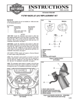
1. See Figure 1. Remove the screw (5) fastening the compass sensor cable clamp to the support bracket, and
pull the old cable from the clamp. Insert the cable from
the new compass sensor into the clamp, and re-fasten
the clamp to the support bracket.
In order to connect the new compass sensor to the compass
display in the motorcycle fairing, the old compass sensor
harness must be cut in the area under the seat. A sixposition Deutsch connector (included in the kit) will then be
assembled to the front portion of the existing harness, and
plugged into the new sensor harness.
2 Remove the old cable from the motorcycle as you lead
the new cable up the right side saddlebag support
bracket (6), and forward along the fender support bracket and frame strut. Secure the new cable with cable ties
from the kit at the same points as the old cable.
NOTE
When cutting the existing harness, make sure the wires from
the front of the bike are long enough to reach the service
harness connector without stretching, pinching or rubbing.
3. Route the cable through the opening in the frame gusset,
under the turn signal/security module (if so equipped) and
behind the battery to the left side of the motorcycle.
1. Cut the wires of the original compass sensor harness in
the area under the seat so that the wires coming from
the fairing will reach the service harness connector.
4. Run the cable along the left side of the battery. Unplug
the existing cable from the switched accessory connector, located in front of the battery. Plug the four-position
Deutsch connector from the new compass sensor into
the accessory connector.
2. Obtain the Deutsch socket, terminals and related parts
from the kit. See a 1998 or later FLT Service Manual for
Deutsch Solid Barrel Contact Crimping Instructions. Follow
instructions to terminate the wires from the old compass
sensor harness.
3. See Figure 2. Insert the terminals into the connector
half as shown.
i05110
1 2 3
4 5 6
4. Insert the seal pin in the unused cavity.
5. Connect the old compass harness to the new sensor
harness.
Open
Orange/White
6. Install the right-side saddlebag. Refer to SADDLEBAG
INSTALLATION in the appropriate Service Manual.
Green
Purple
7. Refer to the Owner’s Manual and follow the instructions to
re-attach the negative battery cable and install the seat.
White
Yellow
1WARNING
After installing seat, pull upward on front of seat to be
sure it is in locked position. While riding, a loose seat
can shift causing loss of control, which could result in
death or serious injury. (00070a)
Figure 2. Connection Diagram
1
16
16
(NNW)
(N)
1
2
15
3
15
(NW)
2
(NNE)
i04776c
14
4
14
(WNW)
13
3
5
13
(W)
(NE)
6
12
12
(WSW)
4
7
11
10
(ENE)
5 (E)
6 (ESE)
7
8
(SE)
(SSE)
9 (S)
10
11
(SSW) (SW)
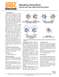
Figure 3a. Zone Chart for the "Lower 48" States
(With Compass Gauge Equivalents)
9
8
Figure 3b. Zone Equivalents on the
Compass Gauge
Figure 3
-J02461
2 of 4