1
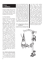
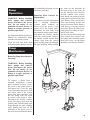
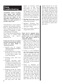
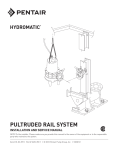
METAL-TO-METAL RAIL SYSTEM INSTALLATION AND SERVICE MANUAL NOTE! To the installer: Please make sure you provide this manual to the owner of the equipment or to the responsible party who maintains the system. Item # E-03-360 | Part # 5625-360-1 | © 2012 Pentair Pump Group, Inc. | 10/29/12 System Description: GeneralIn a Hydromatic Metal-to-Metal Information (MTM) Rail System, the pump is Thank you for purchasing your Hydromatic® pump. To help ensure years of trouble-free operation, please read the following manual carefully. Before Operation: Read the following in struc tions care ful ly. Reasonable care and safe meth ods should be practiced. Check local codes and requirements before installation. Attention: This manual contains important information for the safe use of this product. Read this manual completely before using this product and refer to it often for con tin ued safe product use. DO NOT THROW AWAY OR LOSE THIS MANUAL. Keep it in a safe place so that you may refer to it often. Unpacking Pump: Remove pump from carton. When unpacking unit, check for con cealed damage. Claims for damage must be made at the receiving end through the delivery carrier. Dam age cannot be processed from the factory. WARNING: Before handling these pumps and controls, always disconnect the power first. Do not smoke or use sparkable electrical devices or flames in a septic (gaseous) or possible septic sump. CALIFORNIA PROPOSITION 65 WARNING: This product and related accessories contain chemicals known to the State of California to cause cancer, birth defects or other reproductive harm. 2 raised and lowered in the basin on pipe rails. A hydraulic sealing flange at the pump discharge allows the pump to be connected and removed from the discharge elbow with ease at any time, without entering the wet well. There is no need to disconnect any piping or electrical connections to remove a pump for inspection or routine maintenance checks. A typical system will operate on float control switches. A bottom float control will turn off the pump(s). An additional float control per pump is then used to turn on the pump(s). In a multiple pump station, the pumps are automatically alternated if using a standard Hydromatic panel. Also, additional float controls may be used to indicate high and/or low water sump conditions. The general equipment for a simplex and duplex system includes the following: must have impellers manually rotated (6 revolutions) after setting non-operational for 3 months or longer and prior to electrical start-up. Pumps with tungsten carbide seals must have impellers manually rotated (6 revolutions) after setting non-operational for 3 weeks or longer and prior to electrical start-up. Codes: All codes must be observed. Consult with the local inspector before installation to avoid costly delays. Hydromatic is not responsible for any expense incurred to meet local codes. Pump Installation 1. Concrete Basin(s): Pour one or two concrete systems (one for pumps and control, etc. and one for valves, if required) or obtain precast concrete rings. A 45 degree slope may be poured SimplexDuplex around the in side perimeter of the basin at the bottom to prevent One pump Two pumps solids buildup pro vid ing the slope does not interfere with One discharge Two discharge elbow assembly elbow assemblies the discharge elbow and pump locations. Before beginning One hydraulic Two hydraulic the in stal la tion, refer to the sealing flange sealing flanges “Installation Data” as found in the Hydromatic Engineered Two guide rails Four guide rails Products Catalog. One lifting chain Two lifting chains Follow the Installation Data taking into account the location One door & Two door & of the dis charge pipe, inlet frame assembly frame assemblies pipe, controls, vent pipe, and quire ments of ElectricalElectrical the anchoring re the discharge elbow(s). (All of the controlscontrols above concrete work by others.) Two level Three level controlscontrols Pumps Not Operating or in Storage: Pumps with carbon ceramic seals 2.Discharge Elbow Installation: See “Installation Data” for the proper location of the discharge elbow on the basin bottom. Either cast anchor bolts into basin bottom protruding 2" from basin floor with lockwashers and nuts securing, or drill holes for ex pan sion lag screws to secure elbow to basin bottom. Each elbow requires four anchors (all furnished by others). Each elbow must be level. Length of anchors em bed ded in concrete varies with materials used, but must be sufficient to withstand the weight, torque, and thrust loads imposed by the pump. See “Instructions for As sem bly” (Page 7) for an illustration of the discharge elbow. 3.Discharge Piping (All Supplied by Others): Install vertical discharge piping modules to elbow using bolts, nuts, lockwashers and gasket. Install remain der of the sump discharge pip ing. This typically includes a vertical run of piping appropriately sized and configured to mate with the vertical discharge piping, a ninety de gree elbow, and a horizontal run of piping approximately sized and con fig ured to mate with the valve box or main piping. Install horizontal run extending through the wall of basin. Secure vertical run to the vertical discharge piping using the appropriate method (i.e., flange, weld, gasketed collar coupling) and grout all piping extending through basin walls. NOTE: If using flanged connections be cer tain that adequate clearances are provided throughout for instal lation of bolts, nuts, lock wash ers, and gaskets. If total run of vertical piping exceeds twelve (12) feet, install a piping brace at the approximate midpoint of the piping. Secure brace (i.e., U-bolt with angle iron strap and angle iron extensions) to both piping and wall of basin. 4.Basin Cover(s): The basin cover for the sump and valve box can either be poured con crete or precast. If Hydromatic door and frame assemblies are used, locate the concrete openings with re spect to the discharge elbow mounting studs as shown in the installation data. If the covers are poured, place the door and frame assem bly inside the concrete form and position per installation data. Anchor straps are provided on the door frames to secure them to the concrete. If precast covers are used, remove an chor straps from frame before installing into covers. Either cast four 3⁄8" anchor bolts into the top of the precast cover or drill holes for expansion lag screws. Use either 3⁄8" nuts or stainless steel bolts to secure door and frame assembly to cover. If valves are to be inside the wet well, provide accessways as required for the piping and valves to access piping shutoff valves (see Installation data for general dimensions of accessways). Access ways must be covered and se cured with tamper-proof hardware (by others). 5. Guide Rail Installation: Install the guide rails by attaching the lower end of the guide rail to the plugs on the topside of the discharge elbow. See Page 7 for an illustration of the MTM guiderail mounted to the dis charge el bow. At the top of the guide rails, plumb and then fasten the guide rail to the door and frame assembly via the upper guide rail bracket. 6. Intermediate Guide Rail Bracing: Sump depths of 15' 0" and greater re quire intermediate guide rail bracing. The braces mount on the vertical discharge pipes with U-bolts which are sized according to the discharge pipe size. The number of guide rail braces required are as follows: Sump Depths: 15' 0"–30' 0" – 1 Guide rail brace required 30' 0"–45' 0" – 2 Guide rail braces required 7. Exterior Piping: Install the inlet hub(s) in the side of basin and install inlet piping in the hub and grout, or install inlet pipe(s) directly into basin and grout. Install drain pipe from valve box (if required) to basin. Slope pipe to give proper drainage to basin. Install vent piping in side of basin (if required). Extend piping to a proper elevation above grade (as required by plans and specifications and/or local codes). All piping fur nished by others. See Installation Data for typical piping arrangement. 8. Pump and Sealing Flange: Assemble the Sealing Flange to the pump discharge flange using a gasket between the two. See Page 7 and follow illustration. 9.Pump Installation: Check all piping braces and supports for proper installation and tightness. Attach one end of the lifting cable or chain to the pump eyebolts and the other to a hook supplied on the inside of the hatch frame. 3 Pump Installation Lower the pump into the basin locat ing rail guide between the two guide rails. Attach the upper end of lifting assembly to the hook provided on the inside of the Hydromatic door and frame. 10. Float Switches: Mount the float switch mounting brack et to the door and frame assembly using 3/8 - 16 stainless steel screws. Include a dielectric gasket (by others) between dissimilar metals to avoid gal van ic corrosion. Allow ex cess float cable to loop over mount ing bracket. The sump level is controlled by Hydromatic float switch con trols. The float is held in position in the sump by a weight attached to the power cord above the float. The cord supports the float and is adjusted for height from the sur face. Duplex systems use three con trols: one at both pumps off, one set at one pump on, and one set for both pumps on. Pumps alternate oper ation on each successive cycle with a Hydromatic Q-Panel. The alarm level is usually set above the override level as it is possible for one pump to fail and the other to operate on the override level with the sump level never reaching the alarm level. Do not let floats rest against basin wall or bottom, or entangle with each other or pump(s). 11A. Q-Panel on Mounting Stand: When the Q-Panel mounting stand is used, either cast four 1 ⁄2" anchor bolts into the concrete cover, or drill holes for expansion lag screws and attach stand (bolts 4 or lag screws furnished by others). Insert power and sensor cords from the pumps and all float cords through the bushing into the sump cover. Bolt the panel to the panel stand. (Nuts, bolts, and washers are not supplied.) Make connections between the bottom of the control panel and the basin cover using flexib le conduit and conduit seals (by others). When installing pump power cords, make certain that the cords do not rub against the pump or bottom of the basin. Short en cords to suit the installation. See Bulletin Q-701 for the “Installation and Service Manual” on the electrical Q-Panel system. 11B. Q-Panel Mounted Remote from Basin: If the Q-Panel is remotely located, instead of on the mounting stand at the basin, install coupling through basin wall. Screw protective bushing from inside basin into coupling (all furnished by others). Make connec tions outside station using wiring, conduit seals (pot ted) and con duit to remotely located Q-Panel (conduit and seals not furnished). Insert the power and sensor cords through the coupling provided with the bushing. Grout in coupling goes through sump wall (by others). When installing pump power cords, make certain that cords do not rub against pump or on bottom of basin. Short en cords to suit the installation. See Bul le tin Q-701 for the “Installation and Service Manual” on the electric Q-Panel system. Pump Operations WARNING: Before handling these pumps and controls, always dis con nect the power first. Do not smoke or use sparkable electrical devices or flames in a septic (gaseous) or possible septic basin. See Pump Installation and Service Manual for submersible pump operation on starting system. Clean all trash and sticks from basin and connect pump to piping. For reinstalling the pump, reverse the above procedure. Removing Float Controls for Replacement: To remove a float for replacement from a standard installation (control panel mounted on basin cover), the power is first turned off to the control panel. Disconnect the float leads from the terminals in the control panel. Dis con nect the flexible conduit from the control panel. Remove the flexible conduit and the float control leads from the control panel. Pull the pump cord through the pipe coupling while holding the cords on the underside of the basin cover so the cords do not fall into the basin. Remove flexible conduit from potting head. Break out potting from the potting head and remove the float wire. Remove float cord from the float cord mounting bracket and remove float from basin. Replace 3900 float by reversing removal procedure. Repot the leads in the potting head according to N.E.C. and/or local codes. For the removal of the pumps and float controls from systems with the control panel mounted remote from basin cover, see the Pump Installation and Service Manual. Pump Maintenance Removing Pump from Basin for Servicing: WARNING: Before handling these pumps and controls, always dis con nect the power first. Do not smoke or use sparkable electrical devices or flames in a septic (gaseous) or possible septic basin. To remove a pump from a standard installation (control panel mounted on basin cov er), the power to the control panel is first turned off. Close the plug valve. Disconnect the power cords and sensor cords in the control panel from their terminals. Lift out the pump from the basin by means of the chain or cable. Disconnect the flex i ble conduit, power and sensor cords from the control panel. Pull the pump cord down through the pipe coupling while holding the cord on the underside of the basin cover so the cords do not fall into the basin. 5 Pump Troubleshooting WARNING: Before handling these pumps and controls, always dis con nect the power first. Do not smoke or use sparkable electrical devices or flames in a septic (gaseous) or possible septic basin. The following is a list of common problems and possible solutions. Refer to Pump Installation and Service Manual for any necessary adjusting, dismantling or repair work required on the pump. For Control Panel troubleshooting chart, refer to Control Panel Install ation and Serv ice Manual Q-701. Pump runs but does not pump down the basin with the selector switch on either Hand or Automatic position. 1.Impeller may be clogged. Amperage higher than nameplate will indicate this. 2. Pump rotation may be wrong. Reversing any two line leads on three phase pumps will reverse the rotation. 3.Discharge plug valve may be closed. 4. Plugging anywhere from impeller to sealing flange. This is evident if no water runs out of sealing flange after raising the pump. Pull the pump from the basin to find the clog. 5.Plugging beyond the sealing flange. This is evident if water does run out when pump is operating when disconnecting the sealing flange from the discharge elbow. Remove the check valve, clean out cover and plug valve and other 6 piping, if necessary, inside valve box to find clog. Reassemble all valves and pip ing. If the basin is still not pumped down after the pump is lowered again and the sealing flange is reconnected, proceed in a logical manner to locate and clear the plugging. 6.Discharge head may be too high. Check elevation against design point of pump. 7. Improper discharge flow. Check for correct impeller size and proper voltage. 8.Check for possible broken or clogged forced main. Basin level is pumped down with selector switch on Hand position, but is not pumped down with selector switch on Automatic position. 1. Floats are not hanging free in the basin or are covered with debris. Pump the level down with the se lec tor switch on Hand, so that the floats can be observed. Re lo cate and clean all floats as necessary. 2.If this is a new installation and original start-up, the floats may be miswired into the control panel. Recheck the wiring diagrams and schematics in the panel. If the start and stop floats are hooked in reverse, the pump will short cycle on and off and will not pump the level down. 3. Floats or alternator are malfunctioning. Pull the floats out of the basin, clean them and lay them on the ground. Lift up the stop (lower) float in the left hand, the start (upper) float in the right hand and with the bulbs hanging free, turn selector switch to Automatic. Lower the left hand until the float hits the ground and lies on its side. Nothing should happen. After lowering the right hand in the same manner, the pump should start. When raising the right hand to suspend the float, the pump should continue to run. The pump should stop when raising the left hand to suspend the float. If this procedure does not cause the pump to operate as described, either order new float switches or replace alter nator relay. M-T-M Rail System ACCESS FRAME LIFTING CHAIN (OPTIONAL) UPPER GUIDE RAIL BRACKET GUIDE RAILS INTERMEDIATE GUIDE RAIL BRACKET DISCHARGE ELBOW SEALING FLANGE WITH RAIL GUIDE 7 STANDARD LIMITED WARRANTY Pentair Hydromatic® warrants its products against defects in material and workmanship for a period of 12 months from the date of shipment from Pentair Hydromatic or 18 months from the manufacturing date, whichever occurs first – provided that such products are used in compliance with the requirements of the Pentair Hydromatic catalog and technical manuals for use in pumping raw sewage, municipal wastewater or similar, abrasive-free, noncorrosive liquids. During the warranty period and subject to the conditions set forth, Pentair Hydromatic, at its discretion, will repair or replace to the original user, the parts that prove defective in materials and workmanship. Pentair Hydromatic reserves the right to change or improve its products or any portions thereof without being obligated to provide such a change or improvement for prior sold and/or shipped units. Start-up reports and electrical schematics may be required to support warranty claims. Submit at the time of start up through the Pentair Hydromatic website: http://forms.pentairliterature.com/startupform/startupform.asp?type=h. Warranty is effective only if Pentair Hydromatic authorized control panels are used. All seal fail and heat sensing devices must be hooked up, functional and monitored or this warranty will be void. Pentair Hydromatic will cover only the lower seal and labor thereof for all dual seal pumps. Under no circumstance will Pentair Hydromatic be responsible for the cost of field labor, travel expenses, rented equipment, removal/reinstallation costs or freight expenses to and from the factory or an authorized Pentair Hydromatic service facility. This limited warranty will not apply: (a) to defects or malfunctions resulting from failure to properly install, operate or maintain the unit in accordance with the printed instructions provided; (b) to failures resulting from abuse, accident or negligence; (c) to normal maintenance services and parts used in connection with such service; (d) to units that are not installed in accordance with applicable local codes, ordinances and good trade practices; (e) if the unit is moved from its original installation location; (f) if unit is used for purposes other than for what it is designed and manufactured; (g) to any unit that has been repaired or altered by anyone other than Pentair Hydromatic or an authorized Pentair Hydromatic service provider; (h) to any unit that has been repaired using non factory specified/ OEM parts. Warranty Exclusions: Pentair HYDROMATIC MAKES NO EXPRESS OR IMPLIED WARRANTIES THAT EXTEND BEYOND THE DESCRIPTION ON THE FACE HEREOF. Pentair HYDROMATIC SPECIFICALLY DISCLAIMS THE IMPLIED WARRANTIES OF MERCHANTABILITY AND FITNESS FOR ANY PARTICULAR PURPOSE. Liability Limitation: IN NO EVENT SHALL Pentair HYDROMATIC BE LIABLE OR RESPONSIBLE FOR CONSEQUENTIAL, INCIDENTAL OR SPECIAL DAMAGES RESULTING FROM OR RELATED IN ANY MANNER TO ANY Pentair HYDROMATIC PRODUCT OR PARTS THEREOF. PERSONAL INJURY AND/OR PROPERTY DAMAGE MAY RESULT FROM IMPROPER INSTALLATION. Pentair HYDROMATIC DISCLAIMS ALL LIABILITY, INCLUDING LIABILITY UNDER THIS WARRANTY, FOR IMPROPER INSTALLATION. Pentair HYDROMATIC RECOMMENDS INSTALLATION BY PROFESSIONALS. Some states do not permit some or all of the above warranty limitations or the exclusion or limitation of incidental or consequential damages and therefore such limitations may not apply to you. No warranties or representations at any time made by any representatives of Pentair Hydromatic shall vary or expand the provision hereof. 740 EAST 9TH STREET 490 Pinebush Road, Unit #4 ASHLAND, OHIO, USA 44805 CAMBRIDGE, ONTARIO, CANADA N1T 0A5 419-289-1144800-363-PUMP WWW.HYDROMATIC.COM Warranty Rev. 12/13