1
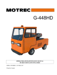
After studying this chapter, you will be able to:
Identify the parts of a tire and wheel.
Describe different methods of tire construction.
Explain tire and wheel sizes.
Parts of a Tire
Although there are several tire designs, all tires have
the same basic parts, Figure 65-2:
• Beads-Two rings that are made of steel wire and
Describe tire ratings.
Identify the parts of driving and nondriving hub
and wheel bearing assemblies.
Correctly answer ASE certification test questions
requiring a knowledge of tires, wheels, hubs, and
wheel bearings.
This chapter introduces the various tire, wheel, and
hub designs used on modem vehicles. It explains how
tires and wheels are constructed to give safe and dependable service. The chapter also covers hub and wheel
bearing construction for both rear- and front-wheel-drive
vehicles. As a result, you will be better prepared to study
later chapters on brakes, suspension systems, and wheel
alignment.
encased in rubber. They hold the tire sidewalls
snugly against the wheel rim.
• Body plies-Rubberized fabric and cords wrapped
around the beads. They form the carcass, or body,
of the tire.
•
Tread-Outer surface of the tire that contacts the
road.
• Sidewall-Outer part of the tire that extends from
the bead to the tread. Markings on the sidewall
provide information about the tire.
• Belts-Sometimes
used to strengthen the body
plies and stiffen the tread. They lie between the
tread and plies.
• Liner-Thin
Tires
layer of rubber that is bonded to the
inside of the plies. It provides a leakproof membrane for the modem tubeless tire.
Automobile tires perform two basic functions: they
act as a soft cushion between the road and the metal
wheel, and they provide adequate traction (friction) with
the road surface.
Tires must transmit driving, braking, and cornering
forces to the road in both good and bad weather. At the
same time, they should resist punctures and wear.
The tires used on early vehicles were solid rubber.
Today's automotive tires are pneumatic, which means
they are filled with air. Internal air pressure pushes out on
the inside of the tire to support the weight of the vehicle.
Today's vehicles use tubeless tires, which do not
have a separate inner tube. The tire and wheel form an
airtight unit. Refer to Figure 65-1. Older vehicles used
inner tubes (soft, thin, leakproof rubber liners) that fit
inside the tire and wheel assemblies.
Tubeless tire
and wheel form
leakproof unit
Metal wheel
Air pressure
pushes outward
to inflate tire
Figure 65-1. With tubeless tires, the tire and wheel form a
leakproof unit. Air pressure pushes outward on the inside of the
tire.
1241
1242
Section 11 Suspension, Steering, and Brakes
may run at different angles. Also, different materials may
be utilized.
Three types of tires found in use today are the bias
ply tire, belted bias tire, and radial tire.
Bias Ply Tire
Body
plies
In a bias ply tire, the plies run at an angle from bead
to bead. The angle is reversed from ply to ply. The tread
is bonded directly to the top ply. See Figure 65-3A.
A bias ply tire is one of the oldest designs, and it does
not use belts. The position of the plies in a bias ply tire
allows the body of the tire to flex easily. This tends to
improve cushioning action. A bias ply tire provides a
very smooth ride on rough roads.
One disadvantage of the bias ply tire is the weakness
of the plies and tread, which reduces traction at high
speeds and increases rolling resistance.
Liner
Wheel
Belted Bias Tire
Figure 65-2. Study the basic parts of a tire. (Goodyear)
Tire Rolling Resistance
Tire rolling resistance is a measurement of the
amount of friction produced as the tire operates on the
road surface. A high rolling resistance would increase
fuel consumption and wear. Typically, rolling resistance
is reduced by higher inflation pressure, proper tire
design, and lower vehicle weight.
Tire Construction
There are many construction and design variations in
tires. A different number of plies may be used. The plies
Bias ply tire
A belted bias tire is a bias ply tire with belts added to
increase tread stiffness. The plies and belts normally run
at different angles. The belts do not run around to the
sidewalls-they
lie under the tread area only. Usually,
two stabilizer belts and two or more plies are used to
improve tire performance. Look at Figure 65-3B.
A belted bias tire provides a smooth ride and good
traction. It also offers some reduction in rolling resistance
over a bias ply tire.
Radial Ply Tire
A radial ply tire has plies running straight across
from bead to bead, with stabilizer belts directly beneath
the tread. The belts can be made of steel, flexten, fiberglass, or other materials. A typical radial tire is illustrated
in Figure 65-3C.
Radial
Belted bias
Stabilizer
belts
A
Body ply
cords run
on bias
B
Figure 65-3. There are three basic tire types. A-Bias
ply tire B-Belted
Radial cord
c
bias tire. C-Radial
body plies
ply tire. (Firestone)
Chapter 65 Tire, Wheel, and Wheel Bearing Fundamentals
1243
Maximum inflation
pressure
DOT serial number
Temperature
index
Traction
index
Load index
Tread wear
index
Maximum
load
Tread plies
Sidewall plies
Figure 65-4. Sidewall markings contain information about a tire. Study the sidewall markings on this tire.
A radial tire has a very flexible sidewall and a stiff
tread, giving it a very stable footprint (shape and amount
of tread touching road surface). This improves safety,
cornering, braking, and wear.
One possible disadvantage of a radial tire is that it may
produce a harder, or harsher, ride at low speeds. The stiff
tread area does not give or flex as much on rough roads.
Tire Markings
Tire markings on the sidewall of a tire give information about tire size, tire model, load-carrying ability,
inflation pressure, number of plies, speed rating, manufacturer, etc. It is important that you understand these tire
markings. Refer to Figure 65-4.
Tire Size
Tire size is given on the sidewall as a letter-number
sequence. There are two common size designations:
alpha-numeric (conventional measuring system) and
P-metric (metric measuring system).
The P-metric size designation is the newest tire identification system. It uses metric values and international
standards. Look at Figure 65-5A.
The letter "P" indicates that the tire is designed for
use on a passenger car. The first number, 155, gives section width in millimeters. The second number, 80, is the
aspect ratio (height-to-width ratio). The R indicates
radial (B means belted bias and D means bias ply). The
last number, 13, shows the rim diameter in inches (not
metric values).
The alpha-numeric
(alphabetical-numerical)
tire
size designation uses letters and numbers to denote tire
size in inches and its load-carrying capacity in pounds.
An example is given in Figure 65-5B.
The first letter, G, indicates the load and size
relationship. The higher the letter, the larger the size
and load-carrying ability of the tire. G is smaller than H,
for example. The second letter, R, means that the tire
is a radial. Bias and belted bias tires do not have a
second letter. The first number, 78, is the aspect, or
1244
Section 11
Suspension, Steering, and Brakes
P-metric tire size:
P
155/80
R-13
~
A
Type tire
(P=passenger
car)
(T=temporary)
(C=commercial)
~
Section width
in millimeters
Height-towidth ratio
(155, 185, 195)
(70,75,80)
I
Alpha-numeric
GR
Load/size
relationship
(E, F, G)
B
Rim or wheel
diameter in
inches
(R=radial)
(B=bias belted)
(D=diag. bias)
(13,14,15,16)
tire size:
78-15
~I
Radial design
Figure 65-5. Note the two tire size designations. A-P-metric
Tire construction
Height-to-width
ratio
Rim or wheel
diameter in inches
(65,70,78)
(13,14,15)
designation. B-Alpha-numeric
designation.
t
Overall
diameter
I
~Width~
is 70%
of
width
UHeight
t
70-series tire
aspect ratio = 70
IU~~~
T
t
r-Width-1
of
width
65-series tire
aspect ratio = 65
Figure 65-7. The aspect ratio is the height-to-width ratio of tire.
Note that a 65 series tire is wider and shorter than a 70 series tire.
Figure 65-6. Points of measurement on a tire. These dimensions are important when ordering new tires or wheels.
(B.F. Goodrich)
height-to-width, ratio. The last number, 15, is the rim
diameter in inches. The points of measure for a tire are
given in Figure 65-6.
Aspect Ratio
The aspect ratio, or height-to-width ratio, in the tire
size designation is the most difficult value to understand.
See Figure 65-7.
Note that, as the number becomes smaller, the tire
becomes more squat (wider and shorter). The aspect ratio
is the comparison of the tire's height (bead-to-tread
distance) and width (sidewall-to-sidewall distance).
A 70-series tire, for example, has an aspect ratio of
70; the height of the tire is 70 percent of the width. A 60
series tire would be "short" and "fat." A 78 tire would be
"narrow" and "tall."
Maximum Load Rating
The maximum load rating of a tire indicates the
amount of weight the tire can carry at the recommended
inflation pressure. The maximum load value-1500
pounds, for example-is printed on the sidewall.
With P-metric tire designations, the load rating is
simply given in kilograms and pounds. The alphanumeric load rating is indicated by a letter. Most alphanumeric size tires are load range B. They are restricted to
the load specified at 32 psi (220 kPa). Where a greater
load carrying ability is needed, load range C or D tires are
used.
Chapter 65 Tire, Wheel, and Wheel Bearing Fundamentals
Maximum Inflation Pressure
The maximum inflation pressure is the highest air
pressure that should be pumped into the tire. Many tires
have a maximum recommended inflation pressure of
32 psi (220 kPa). However, tires with higher load ranges
can hold higher pressures and carry more weight.
Tread Plies
The tire sidewall also includes information on the
number of plies and ply rating. For example, the tire may
be a 2-ply tire, a 2-ply with a 4-ply rating (plies made
stronger than normal), or a 4-ply tire. A greater number
of plies or a higher ply rating generally indicates a greater
load-carrying ability.
Sidewall Plies
The number of sidewall plies is also shown on the tire
sidewall.
DOT Serial Number
DOT stands for Department Of Transportation.
When you see "DOT" on the tire sidewall, the tire has
passed prescribed safety tests.
Following the letters DOT is the DOT serial number,
which identifies the particular tire manufacturer, plant
location, construction, and date of manufacture. The
DOT serial number is stamped into the tire sidewall.
1245
Special Tires and Tire Features
You should be familiar with several types of special
tires and tire features. The automotive technician will
encounter compact spare tires, self-sealing tires, retreads,
and run-flat tires.
Asymmetric Tires
Asymmetric tires have a different tread pattern on the
inner edge than the outer edge. The outer tread pattern is
designed to improve cornering on dry surfaces. The inner
tread pattern is designed to improve traction on wet surfaces. An asymmetric tire must be mounted so the proper
edge faces the outside of the wheel. This type of tire is
generally marked with the word outside to indicate which
way it should be mounted on the wheel.
Directional Tires
Directional tires are high-performance tires designed
to rotate in a specific direction to minimize hydroplaning.
Hydroplaning is a loss of control that occurs when layer
of water prevents the tire tread from contacting the road
surface. Directional tires have an arrow and the word
rotation molded onto their sidewalls. Care must be taken
to mount directional tires in the proper location so they
rotate in the desired direction.
Tire Grades
Tread wear, traction, and temperature grades are normally shown on the tire sidewall according to the
Uniform Tire Quality Grading System.
Tread wear is given as a number. Tread wear ratings
range from 100 to 500. The higher the number, the more
resistant the tire is to wear.
Tire traction is given an A, B, or C rating. A tire with
an A rating would provide the most traction, while a tire
with a C rating would provide the least traction.
Tire temperature resistance is also given as an A, B,
or C rating. A tire with an A rating resists a temperature
buildup better than a tire with a B or Crating.
Speed Rating
A tire speed rating is the maximum allowable
sustained road speed a tire can safely withstand without
failure. Speed ratings range from B (31 mph or 50 km/h)
to Z (149 mph or 238 km/h).
It is important that the speed rating of a tire be higher
than the speed at which the vehicle will be driven. If too
low a speed rating is used, the tire could fail and cause a
fatal accident. This is extremely important if the vehicle
is to be driven in areas where there is no speed limit
(some states and foreign countries).
Spare Tires
A spare tire, or spare, is an extra wheel and tire
assembly that can be installed if the vehicle has a flat tire.
The spare can be a full-size tire or a compact tire.
A full-size spare is a tire of the same size and type
used on the other four wheels of the vehicle. It can be
mounted and used like any other tire. It is being replaced
by compact, lighter spare tires.
Most new cars use a compact spare tire, or space
saver spare, which is much smaller than the normal tire
used on the vehicle. It saves space in the trunk or storage
area. See Figure 65-8.
A high-pressure spare is a compact spare tire that
holds higher-than-normal air pressure (typically about
60 psi). It is inflated when in the trunk and is ready for use.
Some spare tires are not inflated when in storage. A
small bottle of compressed air may be used to inflate the
tire when needed.
A lightweight spare tire has very thin sidewall and
tread construction. Being light, it can be more easily
picked up and mounted on the vehicle. However, the
driving range and maximum speed rating of a lightweight spare are generally lower than those for a compact spare.
1246
Section 11 Suspension, Steering, and Brakes
Run-flat construction
Reinforced
sidewall
Inflation
pressure
Standard tire
Figure 65-8. A compact spare tire is for temporary use only.
This one should be inflated to 60 psi (415 kPa). It requires a
special narrow wheel. (Oldsmobile)
Tech Tip!
Most modem spare tires are designed for temporary use only. Refer to the manufacturer's
specifications on inflation pressure, maximum
driving speed, and the number of miles that can
be driven. Most compact spares should not be
used at speeds over 50 mph and will last only a
few thousand miles.
Self-Sealing Tires
Some tires are self-sealing (seal small punctures).
These tires have a coating of sealing compound applied
to their liners. If a nail punctures a self-sealing tire, air
pressure will push the soft compound into the hole to stop
air leakage. Refer to Figure 65-9.
Retreads
Retreads are used tires that have had a new tread vul-
Run-flat tire
Figure 65-10. Compare the construction of a run-flat tire to that
of a conventional tire. (Bridgestone)
on passenger cars. However, large truck tires are frequently
recapped because of the high cost of new truck tires.
Run-Flat Tires
Run-flat tires have an extremely stiff sidewall construction so that they are still usable with a loss of air pressure. If the tire leaks, you can drive the vehicle to a repair
shop without tire and wheel damage. See Figure 65-10.
The tire will retain most of its shape because the sidewall is strong enough to support vehicle weight. The tire
uses a special rubber compound and a thick rubber sidewall
support insert that helps support the weight of the vehicle.
Wear Bars
Wear bars are used to indicate a critical amount of
tread wear. When too much tread has worn from the tires,
solid rubber bars will show up across the tread. This tells
the customer and the technician that tire replacement is
needed. Look at Figure 65-11.
canized (applied using heat and pressure) to the old carcass, or body. Retreads, also called recaps, are seldom used
Tread wear
indicators
Figure 65-9. Self-sealing tire action. A-Nail punctures the tire.
B-Nail is pulled out. C-Sealing
compound flows into the hole
to prevent air from leaking out. (GMC)
Figure 65-11. When wear bars are visible, a tire is worn
enough to be unsafe and should be replaced. (General Motors)
Chapter 65
Tire Pressure Monitoring Systems
vehicles are equipped with tire
pressure monitoring systems, which alert the driver if
one or more of the vehicle's tires is underinflated. There
Many late-model
are two types of tire inflation systems used in late-model
vehicles: direct systems and indirect systems.
Direct tire pressure monitoring systems use a pressure sensor/transmitter mounted at each wheel. In some
Tire, Wheel, and Wheel Bearing Fundamentals
1247
cases, these sensors are attached to the tire valves. In
other designs, the sensors are held to the wheel with a
metal or plastic strap. See Figure 65-12. If the tire pressure drops below a predetermined value, the sensor on
the corresponding wheel will send a signal to a small
receiver mounted in the passenger compartment. The
receiver then turns on a dash warning light to inform the
driver of the inflation problem. See Figure 65-13.
Pressure
sensor/transmitter
Tire valve
Valve
stem
B
A
Figure 65-12. Some tire pressure monitoring systems use a pressure sensor/transmitter
sensor. B- This sensor is strapped to the inside of the wheel. (Ford, Chevrolet)
mounted at each wheel. A-Valve-mounted
Pressure
sensors
Warning
light
Pressure
sensor
Warning
chime
Sensor
signal
Receiver
Pressure
sensor
Figure 65-13. If one of the pressure sensor/transmitters detects low tire pressure, it will produce a radio signal. A receiver in the
passenger compartment detects the signal and triggers a warning light in the dash. (Toyota)
Section 11
1248
Suspension, Steering, and Brakes
In an indirect tire pressure monitoring system, the
anti-lock brake system components are used to monitor
tire pressure. When pressure in a tire drops, the tire's circumference is reduced. This causes the wheel and tire
assembly to spin faster than the other tires. The computer
interprets the speed sensor signal from the affected wheel
as a drop in tire pressure and triggers a warning light.
A standard wheel consists of the rim (outer lip that contacts tire bead) and the spider (center section that bolts to
vehicle hub). Normally, the spider is welded to the rim.
Figure 65-17 illustrates the various dimensions of a
wheel. Compare this illustration with Figure 65-16.
Note!
All vehicles with a gross vehicle weight rating
ofless than 10,000 lb sold on or after
September 1, 2007, are equipped with a tire
pressure monitoring system.
Wheels
Wheels are designed to support the tire while withstanding loads from acceleration, braking, and cornering.
Most wheels are made of steel. A few optional types are
cast aluminum or magnesium. Refer to Figure 65-14.
Mag wheels, or mags, is a nickname for aluminum or
magnesium wheels. These wheels do not need wheel
covers. See Figure 65-15.
A drop-center wheel is commonly used on passenger vehicles because it allows for easier installation
and removal of the tire. Since the center of the wheel is
smaller in diameter (dropped) than the rim, the tire
bead can fall into the recess. Then, the other side of the
tire bead can be forced over the rim for removal. See
Figure 65-15. Aluminum or magnesium wheels are often called
"mags." They do not need wheel covers. (Ford)
Figure 65-16.
Lug bolt
holes
Lug stud
Pilot
bore
Lug nut
Hub
Figure 65-14. Cutaway shows many
relating to a wheel. (Mercedes Benz)
of the components
Figure 65-16. Study the parts of this conventional
wheel.
drop-center
Chapter 65
Tire, Wheel, and Wheel Bearing Fundamentals
1249
Safety Rims
Valve Stems and Cores
A safety rim has small ridges that hold the tire beads
on the wheel during a tire blowout (instant rupture and air
loss) or aflat (slow leak reduces inflation pressure).
Small raised lips around the rim keep the tire beads
from sliding into the drop-center section. This improves
safety by keeping the tire from coming off the wheel. See
Figure 65-18.
A valve stem is pressed into a hole in the wheel of a
tubeless tire to allow inflation and deflation. The stem is
made of rubber. A threaded metal tube is formed in the
end of the stem. See Figure 65-19.
The valve core is a spring-loaded air valve that is
threaded into the valve stem, Figure 65-19. The valve
core allows air to be added to the tire when an air chuck
(tool for filling tire with air) is placed over the valve
stem. When the air chuck is removed from the valve
stem, the spring pushes the valve closed to prevent air
leakage.
To remove air from the tire, push the center of the valve
core inward. The valve will open, allowing air to escape.
A valve stem cap screws over the threaded valve stem to
protect the air valve and stem threads from dirt, moisture,
r-- Rim width --1
I
Bolt circle
t
• bore
t
diameter
Rim
Pilot
..•.
Figure 65-17.
(Goodyear)
Study
the
spacing
Rear
basic
I~
dimensions
of a wheel.
Figure 65-18. Safety ridges prevent the tire from dropping into
the center well in the event of a flat or a blowout.
(DaimlerChrysler)
Valve -----...
cap
~
~
~valvecoce
(air valve)
Figure 65-19. A-Valve stem snaps into a hole in the wheel. B- The press fit between the stem and the wheel forms an airtight
seal. C- The valve core is an air valve that screws into the valve stem body. The valve cap screws over the end of the stem. (Toyota)
1250
Section 11
Suspension, Steering, and Brakes
and damage. It also helps prevent accidental depression
of the valve and the resulting loss of air pressure.
Hub
Lug Nuts, Studs, and Bolts
Lug nuts hold the wheel and tire assembly on the
vehicle. They fasten to special studs. The inner face of the
lug nut is tapered to help center the wheelan the hub.
Refer to Figure 65-20A.
Lug studs are the special studs that accept the lug
nuts. The studs are pressed through the back of the hub or
axle flange. See Figure 65-20B.
Normally, the lug nuts and studs have right-hand
threads (turn clockwise to tighten). When left-hand
threads are used, the nut or stud will be marked with an
"L." Metric threads will be identified with an "M" or the
word "Metric."
A few cars use lug bolts instead of lug nuts. The bolts
screw into threaded holes in the hub or axle flange.
Lug nut~
Lug
stud
Taper helps
center wheel
on hub
A
Wheel Weights
Wheel weights are small lead weights that are
B
attached to the wheel rim to balance the wheel-and-tire
assembly, preventing vibration. The weights are used to
offset a heavy area of the wheel and tire.
Hub and Wheel Bearing Assemblies
Figure 65-20. A-The lug nut screws onto a lug stud to secure
the wheel to the hub. The tapered end of the nut must contact
the wheel. The stud is pressed into the hub. B-If metric or lefthand threads are used, markings will normally be given on the
nut or stud. (Cadillac)
Wheel bearings allow the wheel to turn freely around
the spindle, in the steering knuckle, or in the bearing support. Most wheel bearings are either tapered roller bearings or ball bearings, Figure 65-21.
The wheel bearings are lubricated with heavy, hightemperature grease. This lets the elements (rollers or
balls) operate with very little friction and wear.
Bearing
cage
Inner race
or ring
Shaft
Stationary
or rotating
shaft
Stationary
or rotating
housing
A
Housing
Outer race
or ring
Rotating
rollers
B
Figure 65-21. Two basic wheel bearing configurations. A-A tapered roller bearing has cylindrical rollers that operate between inner
and outer races. If the shaft is stationary, the bearing will allow the outer housing or hub to turn. If outer bearing mount is stationary,
the shaft or axle can turn in the bearing. B-Ball bearings are also used as wheel bearings, especially on a vehicle's driving wheels.
The balls allow parts to rotate with a minimum amount of friction and wear. (Federal Mogul)
Chapter 65 Tire, Wheel, and Wheel Bearing Fundamentals
•
The basic parts of a wheel bearing are:
•
Outer race-cup or cone pressed
steering knuckle, or bearing support.
• Balls or rollers-antifriction
into hub,
washer that keeps the outer
wheel bearing from rubbing on and turning the
adjusting nut.
elements that fit
or cone that rests on spindle or
drive axle shaft.
There are two basic hub and wheel bearing assembly
designs: those with tapered roller bearings and those with
ball or straight roller bearing assemblies.
Hub and Wheel Bearing AssemblyTapered Roller Bearings
Tapered roller bearings can be used on both driving
and non-driving. The basic parts found in a hub and
tapered roller bearing assembly for a vehicle's non-driving
wheels are illustrated in Figure 65-22. These parts include:
• Spindle-stationary
from the steering
system.
•
shaft extending outward
knuckle or the suspension
Wheel bearings-tapered
roller
bearings
mounted on the spindle and in the wheel hub.
• Hub-outer
housing that holds the brake disc or
drum, front wheel, grease, and wheel bearings.
Grease seal-seal that prevents the loss of lubricant from the inner end of the spindle and hub.
• Safety washer-flat
between inner and outer races.
• Inner race-cup
1251
• Spindle adjusting nut-nut
that is threaded on
end of the spindle for adjusting the wheel bearing.
• Nut lock-thin,
slotted nut that fits over the
spindle adjusting nut.
•
Cotterpin-soft
metal pin that fits through a hole
in the spindle, adjusting nut, and nut lock to keep
the adjusting nut from turning in service.
• Dust cap-metal cap that fits over the outer end
of the hub to keep grease in and road dirt out of
bearings.
Since this hub and wheel bearing assembly does not
transfer driving power, the spindle is stationary. It simply
extends outward and provides a mounting place for the
wheel bearings, hub, and wheel. When the vehicle is
moving, the wheel and hub spin on the bearings and
spindle. The hub simply freewheels. The hub is partially
filled with grease to lubricate the bearings.
Figure 65-23 shows a disassembled view of a nondriving front bearing and hub assembly. Compare these
parts to the ones in Figure 65-22.
Figure 65-24 shows the front drive hub and wheel
bearing assembly for a four-wheel-drive vehicle. N"ote
that it has a driving axle that extends through a stationary
spindle. A special free-wheel, or locking, hub transfers
power from the axle to the hub-disc assembly.
Hub and Wheel Bearing Assembly-Ball
or Straight Roller Bearings
Cotter
pin
Dust
cap
Grease
Ball bearings and straight roller bearings are often
used at both driving and non-driving wheels. In most
cases, the bearings are part of an assembly that includes
the inner and outer races. The assembly is pressed into
the steering knuckle or support.
Figure 65-25 illustrates the basic parts found in a
hub and wheel bearing assembly for the driving wheel of
a front-wheel-drive vehicle. These parts include:
•
Figure 65-22. Typical non-driving, or freewheeling, hub and
wheel bearing assembly for the front or rear of a car. Two
tapered roller bearings allow the hub and wheel to revolve
around the stationary spindle. Grease partially fills the hub to
lubricate the bearings. An inner seal prevents the loss of
grease. A nut on the end of the spindle allows adjustment of the
bearing preload. (DaimlerChrysler)
Outer drive axle-stub
axle shaft that extends
through the bearings and is splined to the hub.
• Ball bearings-antifriction
elements that allow
the drive axle to turn in the steering knuckle or
bearing support.
1252
Section 11
Suspension, Steering, and Brakes
L ~~~
I~:~~~,
I ~~~'
I
9?: i!dl'@@)O)'
pin
1nut
0 Ut er
wheel
.
~:::fJJ
Cone-and-
Lug nut
I~::~
roller assembly
bearing
Wheel cover
tlea,,"g
J~~:~I
Figure 65-23. Disassembled view of a nondriving hub and wheel bearing assembly. Note the part names and relationships. This type
of assembly can be used on the front of rear-wheel-drive cars or the rear of front-wheel-drive vehicles. (Florida Dept. of Voc. Ed.)
• Steering knuckle or bearing support-steering
or suspension component that holds the wheel
bearings, axle stub shaft, and hub.
• Driving hub-mounting
place for the wheel;
transfers driving power from the stub axle to the
wheel.
• Axle washer-special
washer that fits between
the hub and locknut.
•
Grease seal-prevents
lubricant loss between the
inside of the axle and the knuckle or bearing
support.
Figure 65-26 shows an exploded view of another
type of driving hub and wheel bearing assembly.
Compare it to Figure 65-25.
Other Hub and Wheel Bearing Assemblies
Modern vehicles use a wide variation of hub and
• Hub or axle locknut-nut
that screws on the end
of the drive axle stub shaft to secure the hub and
other parts of assembly.
wheel bearing assemblies. For example, many late-model
vehicles use a sealed hub and bearing assembly that contains either ball bearings, straight roller bearipgs, or
Outer
bearing;
Hub with disc
assembly
nut
Adjusting
Flange
and gasket
@-@-~~-~
Thrust
washer
LLocknut
L~k
washer
Figure 65-24. This front hub and wheel bearing assembly is used in a four-wheel-drive vehicle. Compare this unit to those shown
earlier. Note how the drive axle sticks through a stationary spindle. An adjustable hub allows the drive axle to be connected and disconnected from the hub and wheel assembly for two- or four-wheel-drive operation. (Toyota)
Chapter 65 Tire, Wheel, and Wheel Bearing Fundamentals
1253
Note!
Steering knuckle
(bearing support)
Ball bearings and straight roller bearings are
often used in solid rear drive axle assemblies to
reduce friction between the axles and the
housing. Detailed information on rear axle bearings can be found in Chapter 61, Differential
and Rear Drive Axle Fundamentals, and
Chapter 62, Differential and Rear Drive Axle
Diagnosis and Repair.
Power input
from transaxle
Drive axle
shaft spins
inside bearings
Figure 65-25. Driving hub and wheel bearing assembly has
bearings mounted in a stationary steering knuckle or a bearing
support. The drive axle shaft fits through the center of the bearings. The hub is splined to axle shaft. The ball bearings are
lubricated by thick, high-temperature grease.
Highway History
Although Michelin introduced the first steel-belted
radial tire in 1948, radial tires were not standard on
American vehicles until many years later. In fact, it was
not until the gasoline crisis of the early 1970's that
American manufacturers began the switch to radial
tires as a way to improve fuel economy. By 1983, radial
tires were standard equipment on all new American
passenger cars.
Summary
tapered roller bearings. These self-contained units are not
serviceable. In most cases, they are bolted to the knuckle
or support. A few are press fit into the knuckle.
When you need more information on a specific
vehicle, always refer to the factory service manual. It will
explain and illustrate the hub and wheel bearing
assembly clearly. Most designs, however, will be similar.
•
Automobile tires perform two basic functions:
they act as a soft cushion between the road and
the metal wheel. Tires must also provide adequate
traction (friction) with the road surface.
•
Car tires are pneumatic, which means they are
filled with air.
Front wheel bearing assembly
_------~A~------_
Disc-tohub screw
Steering knuckle
(bearing support)
Figure 65-26. Disassembled view of a driving hub and wheel bearing assembly. Study the names of the parts. This type of assembly
is commonly used on the front of front-wheel-drive vehicles. However, it can also be found on rear-engine, rear-wheel-drive sports
cars. (Honda)
1254
•
•
Section 11 Suspension, Steering, and Brakes
Today's vehicles use tubeless tires, which do not
have a separate inner tube. The tire and wheel
form an airtight unit.
Tire rolling resistance is a measurement of the
amount of friction produced as the tire operates
on the road surface.
•
A bias ply tire has plies running at an angle from
bead to bead.
•
A belted bias tire is a bias tire with belts added to
increase tread stiffness.
•
A radial ply tire has plies running straight across
from bead to bead with stabilizer belts directly
beneath the tread.
•
Tire markings on the sidewall of a tire give information about tire size, load carrying ability, inflation
pressure, number of plies, identification numbers,
quality ratings, and manufacturer.
•
Tire size is given on the sidewall as a letternumber sequence.
•
The aspect ratio, or height-to-width ratio, is a
comparison of the tire's height and width.
•
The maximum load rating of a tire indicates the
amount of weight the tire can carry at recommended inflation pressure.
•
The maximum inflation pressure, printed on the
tire sidewall, is the highest air pressure that
should be pumped into the tire.
•
A tire speed rating is the maximum allowable sustained road speed the tire can safely withstand
without failure.
•
Some tires are self-sealing (seal small punctures)
because of a coating of sealing compound applied
to the tire liner.
•
Retreads are old, used tires that have had a new
tread vulcanized (applied using heat and pressure) to the old carcass or body.
•
Run-flat tires have an extremely stiff sidewall
construction so that they are still usable with a
loss of air pressure.
•
A tire pressure monitoring system can detect low
tire pressure and alert the driver if one or more
tires is underinflated.
•
A drop-center wheel is commonly used on passenger vehicles because it allows for easier installation and removal of the tire.
•
A valve stem snaps into a hole in the wheel of a
tubeless tire to allow inflation and deflation.
•
Lug nuts hold the wheel and tire assembly on the
vehicle.
•
Wheel weights are small lead weights attached to
the wheel rim to balance the wheel-and-tire
assembly and prevent vibration.
Important Terms
Tires
Pneumatic
Tubeless tires
Beads
Body plies
Tread
Sidewall
Belts
Liner
Tire rolling resistance
Bias ply tire
Belted bias tire
Radial ply tire
Tire markings
Tire size
P-metric
Alpha-numeric
Aspect ratio
Maximum load rating
Maximum inflation
pressure
DOT serial number
Tread wear
Tire traction
Tire temperature
resistance
. Tire speed rating
Asymmetric tires
Directional tires
Hydroplaning
Spare tire
Self-sealing
Run-flat tires
Wear bars
Tire pressure monitoring
system
Wheels
Drop-center wheel
Safety rim
Valve stem
Valve core
Lug nuts
Lug studs
Lug bolts
Wheel weights
Wheel bearings
Hub and wheel bearing
assembly
Review Questions-Chapter
65
Please do not write in this text. Place your answers
on a separate sheet of paper.
1. What are the two basic functions of a tire?
2. Car tires are __
filled with air.
, which means that they are
3. List and explain the six major parts of a tire.
4. Tire __
__
is a measurement of the
amount of friction produced as the tire operates
on the road surface.
5. Which of the following is not a type of tire used
on passenger cars?
(A) Radial.
(B) Bias ply.
(C) Lateral ply.
(D) Belted bias.
6. What information is commonly given on the tire
sidewall?
Chapter 65
7. A typical tire inflation pressure would be 22 psi
(152 kPa). True or False?
8. How does a self-sealing tire work?
9. A(n)
has small ridges that hold the
tire on the wheel during a blowout.
10. Explain why a valve core is needed.
11.
are attached to the rim to balance
the wheel-and-tire assembly and prevent vibration.
12. Name and describe the basic parts of a wheel
bearing.
13. List and explain the nine basic parts of a hub
and tapered roller bearing assembly.
14. List and explain the seven basic parts of a hub
and ball bearing assembly.
15. A sealed hub and bearing assembly is not serviceable. True or False?
ASE- Type Questions
1. Technician A says one of the functions of an
automotive tire is to provide a cushion
between the road and the metal wheel.
Technician B says one of the functions of an
automotive tire is to provide adequate traction
with the road surface. Who is right?
(A) A only.
(B) B only.
(C) Both A and B.
(D) Neither A nor B.
2. Technician A says automotive tires are pneumatic. Technician B says modern automotive
tires are not pneumatic. Who is right?
(A) A only.
(B) B only.
(C) Both A and B.
(D) Neither A nor B.
3. Technician A says older vehicles used tires
equipped with inner tubes. Technician B says
vehicles always came from the factory
equipped with tubeless tires. Who is right?
(A) A only.
(B) B only.
(C) Both A and B.
(D) Neither A nor B.
Tire, Wheel, and Wheel Bearing Fundamentals
1255
4. Technician A says an automotive tire's beads
are used to stiffen the tire treads. Technician B
says an automotive tire's beads are used to
hold the sidewalls against the wheel rim. Who
is right?
(A) A only.
(B) B only.
(C) Both A and B.
(D) Neither A nor B.
5. Technician A says an automotive tire's body
plies provide a leakproof membrane for modern
tubeless tires. Technician B says an automotive
tire's liner provides a leakproof membrane for
modern tubeless tires. Who is right?
(A) A only.
(B) B only.
(C) Both A and B.
(D) Neither A nor B.
6. Technician A says an automotive tire's belts
form the body of the tire. Technician B says an
automotive tire's belts are sometimes used to
strengthen the plies and stiffen the treads. Who
is right?
(A) A only.
(B) B only.
(C) Both A and B.
(D) Neither A nor B.
7. Technician A says tire "rolling resistance" is
normally reduced by lower inflation pressure.
Technician B says tire "rolling resistance'"' is
normally reduced by higher inflation pressure.
Who is right?
(A) A only.
(B) B only.
(C) Both A and B.
(D) Neither A nor B.
8. Technician A says "belted bias" tires provide a
smooth ride and good traction. Technician B
says "radial" tires have a very stable footprint.
Who is right?
(A) A only.
(B) B only.
(C) Both A and B.
(D) Neither A nor B.
1256
Section 11 Suspension, Steering, and Brakes
9. Technician A says a "bias ply tire" is one of the
newest tire designs and is equipped with belts.
Technician B says a "bias ply tire" is one of the
oldest tire designs and does not use belts. Who
is right?
(A) A only.
(B) B only.
(C) Both A and B.
(D) Neither A nor B.
10. Technician A says a radial ply tire's belts are
sometimes made of steel. Technician B says a
radial ply tire's belts are sometimes made of
fiberglass. Who is right?
(A) A only.
(B) B only.
(C) Both A and B.
(D) Neither A nor B.
11. Technician A says tire markings on the sidewall of a tire give information about tire loadcarrying ability. Technician B says tire
markings on the sidewall of a tire provide the
maximum recommended inflation pressure.
Who is right?
(A) A only.
(B) B only.
(C) Both A and B.
(D) Neither A nor B.
12. Technician A says most automotive wheels are
made of steel. Technician B says most automotive wheels are made of aluminum. Who is
right?
(A) A only.
(B) B only.
(C) Both A and B.
(D) Neither A nor B.
13. Technician A says wheel bearings in several
car models are the tapered roller bearing type.
Technician B says wheel bearings in certain
car models are the ball bearing type. Who is .
right?
(A) A only.
(B) B only.
(C) Both A and B.
(D) Neither A nor B.
14. While discussing the basic parts of an automotive wheel bearing, Technician A says the
bearing's outer race is sometimes pressed into
the automobile's steering knuckle. Technician
B says a wheel bearing's outer race is sometimes pressed into the hub. Who is right?
(A) A only.
(B) B only.
(C) Both A and B.
(D) Neither A nor B.
15. Technician A says a steering knuckle is a basic
component in a driving hub and wheel bearing
assembly. Technician B says an inner drive
axle is a basic component in a driving hub and
wheel bearing assembly. Who is right?
(A) A only.
(B) B only.
(C) Both A and B.
(D) Neither A nor B.
Activities-Chapter 65
1. Using a section of an old worn tire, prepare a
cutaway teaching aid showing the different parts
and layers of the tire.
2. Prepare an overhead transparency that explains
tire and wheel sizes and tire ratings.
3. As a classroom demonstration, disassemble and
identify the parts of a hub.