1
Electrical Instructions
202P7 CRT
5
Go to cover page
1.
1.1
General point
During the alignment and measurement supply a distortion free
3.1.2
Set VG2 (screen) to fully anti-clockwise (zero beam current).
3.1.3
To apply a 69KHz/85Hz cross hatch signal.
3.1.4
Adjust R3157 (B+) to obtain 230 V +/- 0.5 VDC across C2131.
4.
H-deflection supply voltage adjustment
AC-mains voltage to the apparatus via an isolating transformer
with a low internal resistance.
1.2
1.3
All voltages have to be measured or applied with respect to
ground,unless otherwise stated.
4.1
Apply a 69 kHz / 85Hz signal.
Note: Don't use heatsink as ground.
4.1.1
Adjust R3698 (EHT) to obtain 27.0 +/- 0.2kV at CRT anode at
zero beam current for SDI 21" DFT tube. Glue fix the R3698VR.
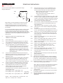
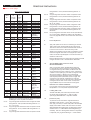
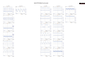
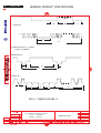
The term "Linear RGB" is meant the 0.7Vpp video with separate
sync. (TTL level).The factory preset timing formats from pattern
4.1.2
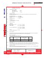
Monitor the following auxiliary voltages.
generator "CHROMA- 2250" are shown in TABLE 1 to 36.
+ 8.0V
SOURCE ACROSS C2362 +
8.0V +/- 0.5 VDC
1.4
Any external voltage source should have low internal impedance.
+ 5.0V
SOURCE ACROSS C2143 +
5.0V +/- 0.5 VDC
1.5
The alignment has to be done in room temperature 25 ± 5 °C.
+ 12.0V SOURCE ACROSS C2361 + 12.0V +/- 0.5 VDC
1.6
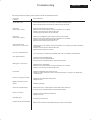
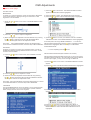
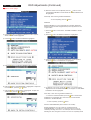
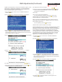
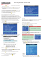
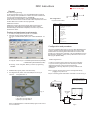
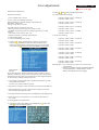
Digital control buttons for
+ 15.0V SOURCE ACROSS C2134 + 15.1V +/- 1.0 VDC
OSD MENU:
Language
-Language: multi-language (8 languages)
Input
-Input signal selection
Zoom
- Zoom
Adjust horizontal
-Adjust position
-Adjust size
Adjust vertical
-Adjust position
-Adjust size
Adjust shape
-Adjust side curve
Pincushion
Balanced
-Adjust side angles
Trapezoid
Parallelogram
-Rotate image
Rotate
Adjust color
-9300 °K for general use
-6500 °K for image management
-5500 °K for photoretouch
-sRGB
-Smart mode
-Professional mode
Reset to factory settings
- No
-Yes
Extra Controls
-Adjust moire
Horizontal
Vertical
-Degauss
-Adjust convergence
Horizontal
Vertical
-Adjust purity
NS purity
-Auto calibrate OFF AUTO
- 15.0V SOURCE ACROSS C2137 - 15.4V +/- 1.0 VDC
+
6.3V SOURCE ACROSS D6143 +
6.1V +/- 0.5 VDC
+230.0V SOURCE ACROSS C2131 + 230.0V +/- 0.5 VDC
+ 80.0V SOURCE ACROSS C2133 + 82.0V +/- 2.0 VDC
5.
5.1
General conditions for alignment
During all alignments, supply distortion free AC mains
voltage to set via an isolating transformer with low internal
impedance.
5.2
All measurements are carried out at nominal mains voltage,
5.3
Align in pre-warmed condition, at least 30 minutes
5.4
Purity, convergence, geometry and subsequent alignments
unless otherwise stated.
warm-up with nominal picture brightness.
should be carried out in magnetic cage with correct magnetic
field.
Northern hemisphere: H = 0, V = 430mG, Z = 0 .
Southern hemisphere: H = 0, V = - 520mG, Z = 0 .
Equatorial Support
5.5
: H = 0, V =
0 mG,
Z = 0.
All voltages are to be measured or applied with respect to
ground,unless otherwise stated.
Note: Do not use heatsink as ground.
5.6
Any external voltage sources should have a low internal
5.7
Adjust function controls to center position except for contrast
5.8
The white balance and purity has to be adjusted in subducted
impedance.
control which should be set to MAX.
lighted room.
5.9
All alignments have to be done in a room with a temperature
of 25 +/- 5° C.
5.10
Adjust picture tilt for correct TOP/BOTTOM lines Via I2Cbus.
5.11
All the alignment can be done only when set is working
(Picture tube should be mounted without tilt CRT cabinet)
in 'factory mode' - pressing the 'Right' and 'left' keys together
2.
Pre warm-up
2.1
Align in pre-warmed condition at least 30 minutes during
2.2
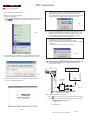
Warm up the monitor by pushing power switch and OSD key
while power on the test set, or by CAA test controller.
Prepare the test set in 'factory mode' before the set alignment.
manufacturing.
3.
Main-chassis alignment
6.
X-ray protection adjustment
6.1
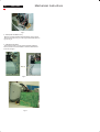
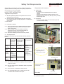
Set the brightness and contrast controls to minimum. Connect
EHT meter
the high tension cap of CRT, set X-ray adj. R3695 to maximum
3.1
3.1.1
Power supply adjustment
To preset potmeter R3157 (B+) and R3698 (EHT) to center
position.
activation voltage(fully clockwise, viewing from component side)
and then turn on the set.