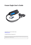
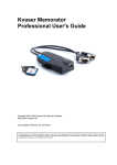
1
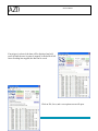
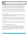
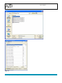
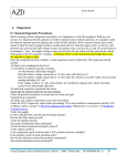
Service Manual 11 Software 11.1 G1 Battery and Vehicle Diagnostic Software The vehicle diagnostic tool is intended to give visibility into the inputs/outputs and the operating state of the vehicle controller (DICO), the ESS, and provide a method of checking the functionality of the instrument cluster. It communicates with the vehicle over the powertrain CAN bus through connector C024s. The drop-down menus on the home screen allow the user to choose what kind of vehicle they are working on. These selections determine which windows will open when the ‗Open‘ button is pressed. The check boxes on the centre-right of this screen allow the user to choose which diagnostic windows to display. Azure Dynamics Series Hybrid Electric Vehicle – 2006/7 Shuttle Bus MAN500666 Rev A 134 Service Manual 11.1.1 ESS Diagnostics Screen This page displays all the available Gen II battery diagnostics. Some of the displays will not update if the battery software version is not 5.4.0 or newer. A L G B M H I N C D J E K O F No. Section States Description Azure Dynamics Series Hybrid Electric Vehicle – 2006/7 Shuttle Bus MAN500666 Rev A 135 Service Manual A Vehicle Command B Battery Status C Power Limits D Module Voltages E Temperatures F Pack and Link Voltages ON/OFF G Pack State Unavailable Idle Disconnected Precharging Connected Alert Forced Disconnect Sleep H Isolation Status OK Alert Not Measured I Clear Stored Faults This is the only bit sent by the DICO to control the battery pack. When the Connect command is ON, the battery will precharge the DC bus and remain connected to the DC bus until the Connect command is removed (unless there is a critical fault requiring the battery to open contactors on its own). Overall pack operating data: pack voltage, current, SOC and software version. Note that the software version will only show up correctly in SW versions 5.4.0 and newer. These are limits sent by the pack indicating how much charge and discharge are allowed – this calculated by algorithms based on voltage levels, life expectancy and module voltage delta prevention. The maximum and minimum cell module voltages. If there is an imbalance in the module voltages, it can be spotted quickly here. The maximum and minimum cell temperatures along with coolant temperature are listed. The pack voltage is measured internal to the pack, while the link voltage is measured external to the contactors – i.e. it is a measurement of the voltage on the vehicle DC bus. Pack state indicates the current pack status. The most frequent states used are: Disconnected – neither contactor is closed, no electrical connection to vehicle DC bus Precharging – pack is precharging the vehicle‘s DC bus, one main contactor and the precharge contactor are closed Connected – both main contactors are closed, pack is electrically connected to vehicle DC bus. Alert – there is an active fault in the battery pack Forced Disconnect – due to a critical active fault, the battery will open contactors The battery pack performs a check on the resistance level between either DC terminal and the chassis ground. The resistance value measured is indicated along with a state indicating whether a fault was found. The reporting of this value is heavily filtered. This button allows the fault history (item M) to be cleared. Azure Dynamics Series Hybrid Electric Vehicle – 2006/7 Shuttle Bus MAN500666 Rev A 136 Service Manual J SOC K Analog Input Voltages L Active Battery Faults M Battery Fault History N O Temperature Sensors Module Voltages This function allows you to re-set the SOC of the pack and to disable critical faults (for the key-cycle). There is a lockout mechanism in the battery software that will force a critical fault if the SOC is less than 5% and not allow precharge. This can be worked around with this function allowing the vehicle the chance to charge the battery. The measured voltages on the LV input pins to the connector. Allows for easy diagnosis of 12V power/ ground supply to the pack. Miscellaneous Fault This buffer displays the current faults in the pack. These Critical Fault fault types are categorical; the specific fault is given in the Module Fault stored history. Precharge Fault Input Fault See battery This buffer displays all the stored faults. This buffer will diagnostics keep accumulating fault information until it is cleared by definition. a service tool. All the module temperature sensors are displayed. All the module voltages are displayed. Azure Dynamics Series Hybrid Electric Vehicle – 2006/7 Shuttle Bus MAN500666 Rev A 137 Service Manual 11.1.2 Vehicle Diagnostics Screen 1 2 4 3 5 6 7 1. 8 CAN Messages This screen gives visibility to the CAN message IDs active on the CAN bus. The tool can be plugged into either the powertrain CAN bus (C024S) or the Drive CAN bus (C100S) to monitor CAN messages. The expected messages from the DICO, DUO inverter and battery pack are shown on the top. If these messages are not present, it indicates that there is a potential issue with power supply, grounding, or communication with this component. Note that it is not necessary to check that ALL messages are present from a given component, just enough to ensure that the component is ‗live‘. Azure Dynamics Series Hybrid Electric Vehicle – 2006/7 Shuttle Bus MAN500666 Rev A 138 Service Manual 2. Inputs This display allows the user to check that various inputs are functional. Input Description Ignition Switch This input reads the key-start request from the ignition. ABS Event Input senses whether the ABS is active on the vehicle. An active ABS signal causes the vehicle to turn off regenerative braking. Dummy Connector Input senses whether the dummy connector is connected. This connector is used as a vehicle lockout mechanism – if this connector is not in place the vehicle will not go into HV mode. Electric Mode Momentary switch input which requests EV mode. EV mode may be disallowed due to low SOC (<40%) or due to the minimum hybrid mode time requirement (30s). Regen Switch Momentary switch input which requests regen to be disabled. Again this request may be ignored due to a minimum time requirement for regen to be enabled (30s). Brake Switch Brake switch input from brake pedal. Safety Controller The safety controller is a wired signal between the DICO and DUO inverter. It is controlled by the VCU to turn-off the power phase of the inverter in case there is a serious fault in the system. Faults that activate the safety controller will be recorded in the VCU error diagnostics. During key-on the signal will be low initially; it will then cycle low/high (handshake with the DUO) and then stay high while in HV mode. If there is a serious system fault, this signal will be low. Alternatively if the there is a problem with the integrity of the safety controller line, this signal will be low. Charger Ready This signal sent from an external charger indicates that the charger is ready. Vehicle Ready Internal variable indicating vehicle in Park position, dummy connector ON and charger ON signal – all the conditions to enable external charger operation. Charging Internal software variable that indicates contactors are closed and charging demand is requested (PWM signal to charger). Finished Internal software variable that indicates that external charging has been terminated. Potential reasons for exiting out of the charging status: 1. Loss of charger ready signal – even a momentary signal blip will stop charging. 2. Max module temperature > 50˚C. 3. (Max – min module voltage) > 1V (DICO parameter ID 54) 4. Min module voltage dV/dt < 0 for > 500ms 5. Pack voltage > (420V – 0.61(V/˚C) x max module temp) Fuel Level Gasoline / Diesel fuel tank fill level. AP POT1 Accelerator pedal potentiometer 1 (Gasoline only). AP POT2 Accelerator pedal potentiometer 2 (Gasoline only). If there is an issue with either of the two accelerator pedal tracks, a critical fault will be flagged and drive will not be allowed. The diesel vehicle AP has a single channel along with a low idle switch. Oil Pressure Oil pressure signal (PASS/FAIL). If one failed measurement is recorded, this fault will be latched until key-off. 3. Vehicle Alerts Azure Dynamics Series Hybrid Electric Vehicle – 2006/7 Shuttle Bus MAN500666 Rev A 139 Service Manual Under the vehicle alerts section, there is an active alert buffer indicating system faults that are currently active. The table below lists all the fault states. Code Accelerator pedal correlation error Loss of ECU CAN Motor or Generator performance reduction Power limit Description There is a short to ground or power on one or both accelerator pedal tracks or the tracks do not correlate. Diesel vehicles only. VCU not receiving CAN data from the engine ECU. Over temperature or other fault condition exists in motor or generator, components are power limited. Check temperatures, error diagnostics. The power limit lamp on the IC is ON. The vehicle max power has been reduced to 85kW (from 110kW). Solid: Potential causes: ESS power limits < 10kW (hyst = 5kw). ESS pack state in Alert mode (current fault state). Low fuel (<5%). Low oil pressure (latched for key-cycle). Powertrain temperature gauge = 100%. Engine has overheated since last keycycle (130°C Gasoline, 120°C Diesel). Flash: Vehicle is in LimpHome Mode. Potential causes: ESS pack failed to precharge or loss of CAN or serious fault requiring energy storage pack to open contactors. Engine run failure Engine failure while running. If code appears frequently, check engine error diagnostics. Engine start failure Engine failure after start. If code appears frequently, check engine error diagnostics. System failure There has been a system failure, consult error diagnostics. Under voltage The inverter DC bus voltage is lower than the reference value. This failure will always appear when the vehicle is not in high voltage mode. Over voltage The inverter DC bus voltage has exceeded the maximum limit. Check error diagnostics. System over temperature One of the components has exceeded maximum temperature. Refer to the powertrain temperature section in the Instrument Cluster Warning Lights chapter. Battery non-critical fault Potential causes: ESS power limits < 10kW (hyst = 5kw). ESS pack state in Alert mode (current fault state). Battery failure fault Battery failure fault – ESS pack failed to precharge or loss of CAN or large module voltage delta (>3V) or serious fault requiring energy storage pack to open contactors. Generator fault Generator fault, consult error diagnostics. Motor fault Motor fault, consult error diagnostics. The battery status section indicates the pack state and precharge status. These are the same status flags as listed in the ESS diagnostics page, but placed here for convenience. The different states are described in the previous section. Azure Dynamics Series Hybrid Electric Vehicle – 2006/7 Shuttle Bus MAN500666 Rev A 140 Service Manual Also indicated in this section is the instrument cluster power limit and service lamp flags. The reasons why these lights come on can be found in the instrument cluster lamp definition section. Beside the battery status section is the battery CAN errors. These fault flags indicate if the VCU has flagged a watchdog fault with battery message ID 250, 254 or 256h. The watchdog flags are set if there are no messages received within a 2 second period. This requires 20 consecutive missed messages for ID 250 and 256 (100ms period), and 10 missed messages for ID 254 (200ms period). 4. Outputs This section allows the user to manually control selected digital outputs from the VCU. This section should be used for the troubleshooting of a component or system, where it is necessary to send the enable signal to verify functionality. To use this section, one must use Siadis to set the VCU parameter 399 – SIA_Selector bit 6 equal to 1. This can be done by flashing a special file normally used for commissioning purposes only, or re-setting that parameter by itself. Once this parameter is set, control of the VCU messages is done by external CAN request, and normal vehicle functionality is disallowed – i.e. the vehicle will not go into HV mode with this parameter set. 5. Cooling System The temperatures from many of the powertrain components are listed here. More details on the de-rating temperatures can be found in the instrument cluster warning lights section of this manual. The battery coolant temperature is the only coolant temperature sensor in the system, the rest are component temperature sensors. Note that there are two temperature sensors in the motor, generator, and several in the inverter. If an issue is suspected with a temperature sensor in one of these components, it will most likely not be indicated here, but can be viewed with Siadis. Refer to the Siadis error diagnostics section for more details. 6. Operational Feedback In the power levels section, the drive motor and generator target (or reference) values are listed along with the actual values. Also listed is the battery power supplied. In the vehicle operational parameters section, the engine speed, drive motor torque, inverter DC bus voltage, and battery voltage are displayed. Also the accelerator pedal command sent from the VCU to the engine is shown, (idle = 13.12%, full throttle = 50.35%) with the engine power controller. The power controller adjusts the feed-forward demand (i.e. throttle demand mapped versus engine speed) based on feedback of the actual power output of the genset. 7. PWM Outputs The VCU sends two PWM output channels to the PWM to Analog unit which converts them to analog signals that communicate an accelerator pedal input to the engine (TAC module). This section allows for control of these PWM outputs to test the functionality of the PWM to Analog and TAC module. Using the Azure Dynamics Series Hybrid Electric Vehicle – 2006/7 Shuttle Bus MAN500666 Rev A 141 Service Manual Tech II (or a similar engine diagnostic tool) one can monitor the simulated input channels (typically grouped under TAC module data). The control of the outputs with these buttons needs to be enabled via calibration, similar to the digital output section. 8. Gear Selection The gear selection section indicates the current gear reading along with all gear selector sensor inputs. The logic for the different gear positions is also shown for reference. VCU Error Diagnostics The button in the bottom right corner of the vehicle diagnostics screen allows the user to view the VCU‘s error diagnostics. The newest diagnostic codes are placed at the bottom of the buffer. A B C D E F A. Diagnostic Error message – consult the Siadis Error Diagnostics section of this manual for troubleshooting instructions related to diagnostic code. B. Component – this is the controller in which the error has occurred – vehicle controller (DICO), generator or motor (both motor and generator controller internal to the DUO inverter). C. Count – this is the number of times the error has occurred in this buffer. The buffer is a first in, first out design, however if the newest code already exists in the buffer, the oldest identical code will be deleted, and the new code will have its count incremented. D. Time – the VCU has an internal clock which counts the number of hours since the controller was initialized. The ‗time‘ at which the error is recorded is shown in this column, and can be compared against the current controller ‗time‘, viewable with Siadis (top right corner of screen). E. Time Since Key-on – this is the elapsed time since key-on at which the error was recorded. This data is useful for determining when the error occurred in the drive cycle. The maximum time possible is 4:15 after key-on, and any error occurred after this time is recorded as 4:15. F. Operational Data at Time of Error – this is a snapshot of the vehicle operational data at the time the error occurred. Azure Dynamics Series Hybrid Electric Vehicle – 2006/7 Shuttle Bus MAN500666 Rev A 142 Service Manual 11.1.3 Instrument Cluster Diagnostics Page This screen allows the user to send commands to the instrument cluster to visually verify that all the lights and gauges are functioning correctly. Note that the DICO needs to be unplugged for this to work correctly; otherwise the lights and gauges will receive conflicting messages and the feedback will not be accurate. The buttons towards the top of the page control the lights, and the gauges are controlled by entering a number in the appropriate box and then clicking the appropriate ‗Send Message‘ button. Note that the values that can be entered into the boxes are restricted to those within the range given to the left of the box. 11.1.4 Azure Dynamics Series Hybrid Electric Vehicle – 2006/7 Shuttle Bus MAN500666 Rev A 143 Service Manual ACAN Trace To record a trace of the system operation, click on Run ACAN-Trace. This will start the ACAN Program. ACAN-Trace Window Set File Location The first time ACAN-Trace is run, it will be necessary to set the file location. Click on options and then either type in the path to the ACAN template or click on browse to search for the file. When the file location has been entered, click on OK. Azure Dynamics Series Hybrid Electric Vehicle – 2006/7 Shuttle Bus MAN500666 Rev A 144 Service Manual Select the data that you want to record. Selecting ― All‖ will record all the CAN data, ― Battery‖ will record all the battery messages, or ― Manual‖ allows the selection of a range of messages. Select the Break options if required. If break options are selected, data will not appear in the window until the trigger of one of the selected options is met. More than one option may be selected. When the trace is started, data will be recorded until the buffers are filled. Once the buffer is full, the oldest data will be written over with the newer data. When the trigger conditions occur, the data will be saved with the trigger placed in the middle of the file. When the trace is started, data will be recorded but not displayed until an event triggers the program. Once the trigger occurs, data before and after the trigger is saved until the buffer is filled. At that point, the raw data will be displayed in the window. Azure Dynamics Series Hybrid Electric Vehicle – 2006/7 Shuttle Bus MAN500666 Rev A 145 Service Manual If no trigger is selected, the data will be displayed and will scroll up until the trace is paused, stopped, or the buffer if full. Once recording has stopped, the data can be saved. Click on File, Save, and a save option screen will open. Azure Dynamics Series Hybrid Electric Vehicle – 2006/7 Shuttle Bus MAN500666 Rev A 146 Service Manual To save the file with the ― Normalized Data‖ option, it is necessary to have MS Excel installed on the computer. Click on Browse and select the proper symbol file to use. For gasoline vehicles, select the GasSymbol.sym file that corresponds to the vehicle Energy Storage System. The file should be located in the same directory as the ACAN-Trace program file. Click on OK. Click on Browse for the ― Target File- Normalized Data‖ and enter a file name to save the data as. This is a name that you chose, normally something related to the vehicle such as a unit number with the date. Azure Dynamics Series Hybrid Electric Vehicle – 2006/7 Shuttle Bus MAN500666 Rev A 147 Service Manual If ― Raw Data‖ or ― Both Formats‖ is selected, click on Browse for the Target File- Raw Data and enter a file name there as well. When all required fields are entered, click on Save. For the Normalization Data, the option of selecting the data to save allows the selection of all messages, battery messages only, or specific messages. Normal selection would be All or Battery Only. Once the selection has been made, click on OK. It will take a few minutes for the software to save the file in the Normalization Data mode. The file will be saved as the name you created with the extension XLS. This file can be opened with MS Excel. The Raw data file will have an extension TRC and can be opened with Notepad. This window lists the IDs of all the messages that were received during the trace. Since normalizing and saving the data for all the messages can be quite time consuming, it is possible to only select certain messages for normalization. When a message ID is clicked, all the signals contained in that message are displayed in the middle of the window. This type of save will also automatically generate some plots if the necessary messages are selected. There is a note at the top of the window that specifies which messages are required to have the data plotted. These plots include a variety of ESS data, as well as the status of the ― triggers‖ that can be used with a continuous trace. The plotting functionality requires an Excel Template file. Specify the location of this file (provided with ACAN Trace), under the Options menu in the main window. Azure Dynamics Series Hybrid Electric Vehicle – 2006/7 Shuttle Bus MAN500666 Rev A 148 Service Manual ACAN-Trace Sample opened with Notepad ACAN-Trace Sample opened with Excel Azure Dynamics Series Hybrid Electric Vehicle – 2006/7 Shuttle Bus MAN500666 Rev A 149 Service Manual 11.2 Siadis For more advance vehicle diagnosis, as well as for flashing calibration files, the Siemens Siadis software tool is used. Siadis can be used to verify code version in the inverters, load new parameters, monitor variables in real-time, log variable traces, and view, save, and clear error diagnostic codes. Siadis uses CAN to communicate with the DUO inverter and the DICO and communicates via the C100s D-sub. Note: There exists two separate software license files (SiadisExpert.key). One intended for Azure technicians is fully featured, while the other is intended for outside technicians working on the G1 product. This license is limited in that it does not allow the user to change parameters in the DICO or the DUO and does not allow access or the ability clear the error diagnostics in the inverter. However it does allow the users to view all variables, record traces and view/clear error diagnostics in the DICO. 11.2.1 Connecting Before starting Siadis, make sure that the CAN Peak-Dongle software is properly installed (contact Azure Dynamics Product Support for latest installation package) and that the CAN Peak-Dongle is connected to the laptop (either through the parallel or PCMCIA ports). Tip: The parallel port Dongle must to be connected to the laptop when the computer is powered up. If it wasn‟t, then Siadismay fail to communicate with the vehicle. If this happens, go to the Start Menu Control Panel CAN Hardware. Under the „General‟ tab in the „Properties of CAN-Hardware‟ window, press the <Add> button then select „Peak Dongle – CAN SJA EPP‟for Hardware Type, „0378‟ for I/O Address and „7‟for Interrupt no. Press <OK> to accept the changes and <OK> again to exit the Properties window. Next, connect the laptop via the dongle to connector C100S on the vehicle using a straight-through serial cable and make sure that the system is powered-up (vehicle is in key-on position). You are now ready to start using Siadis. 11.2.2 Starting the Program and Component Selection To start the program, double-click on the Siadis icon on the desktop or (if not available) click on the Start menu at the bottom left of the screen then go to All Programs SiadisExpert SiadisExpert. The program window will pop up and Siadis will automatically attempt to connect to any components available on the CAN bus (see figure below). To select a component, click on the appropriate box in the Component Selection window in Siadis. All commands and displays will pertain to the selected component until a new component is selected. Azure Dynamics Series Hybrid Electric Vehicle – 2006/7 Shuttle Bus MAN500666 Rev A 150 Service Manual Siadis Main Window. In this capture, Siadis has found a DICO, Motor, and Generator Inverter. The DICO controller is selected and is showing normal CAN communications (green indicator at top right corner). Siadis Main Window. In this capture, the Generator controller is selected but Siadis is showing a loss of CAN communications. 11.2.3 Viewing Data Select the component you would like to connect to. Go to the ‗View‘ menu and select ‗Data List‘. A new window will pop up. To choose variables, right-click anywhere in the ‗Data List‘ window. This will cause another window titled ‗Config Data List‘ to appear showing all available variables. Select desired variables to view by checking the box next to them and press <OK> when done. The selected variables will now appear in the ― Data List‘ window with their real-time values displayed next to them. Azure Dynamics Series Hybrid Electric Vehicle – 2006/7 Shuttle Bus MAN500666 Rev A 151 Service Manual 11.2.4 Downloading Parameters Select the component you would like to download parameters to. From the ‗View‘ menu, select ‗Parameter‘. A new ‗Parameter‘ window will pop up displaying the current parameters in the inverter with their values. To download a Parameter file: In the ‗File‘ menu, select ‗Open Parameter‘ Choose the desired parameter file by navigating to its saved location then pressing <Open> in the dialog box. A valid parameter file will have a *.par extension The new parameter values will now appear under the ‗Change Buffer‘ section in the Parameter window. Press the <Download Change Buffer> button at the top of the window. The values of the parameters under the ‗real parameters‘ heading will now change to the new values, and the parameters under the ‗Change Buffer‘ section will disappear. At this point the values are only stored in the RAM memory, and will be erased if the power is cycled to the controllers (i.e. if the key is turned off). Save the new values to permanent memory by going to the ‗EEPROM‘ menu in the main ‗Siadis-Expert‘ window and selecting ‗Prog. EEPROM‘. If programming is successful you will get the message: eeprom – programming o.k.! Press <OK>. You have now successfully downloaded a parameter file. Repeat process for other components as necessary. To change individual parameters manually: After step 2 above, click on the parameter to be changed under the ‗Real Parameter‘ section of the ‗Parameter‘ window. The parameter will now appear in the ‗edit line‘ section of the window. Enter the new value either as a binary, hex, or decimal value under the appropriate column. Accept the changes by pressing <Enter> on the keyboard, or by pressing the <Add to Change Buffer> button. If <Enter> is pressed, the new value will be automatically updated. If <Add to Change Buffer> is used, the new value will be placed in the in the buffer until it is downloaded into the inverter as outlined in step 3(d). Save the changes permanently by following step 3(e)-(f). Tip: The Menu tool bar contents change depending on the window you have active, so if you can‟t find a command you are looking for, double check that you are looking at the correct window. 11.2.5 Uploading Parameters Select the component you would like to upload parameters from. From the ‗View‘ menu, select ‗Parameter‘. A new ‗Parameter‘ window will pop up displaying the current parameters in the inverter with their values. In the main ‗Siadis-Expert‘ window, select ‗Save Parameter‘ from the ‗Files‘ menu. You will now be prompted to enter the file name. Choose an appropriate name and use the default extension (*.par). Press the <Save> button. You have now successfully uploaded and saved the parameters from the inverter. Repeat the steps for the other components as required. Azure Dynamics Series Hybrid Electric Vehicle – 2006/7 Shuttle Bus MAN500666 Rev A 152 Service Manual 11.2.6 Checking Error Diagnostics Select the component you would like to view the fault log for. In the main ‗Siadis-Expert‘ window, select ‗Error Diagnostic‘ from the ‗View‘ menu. A new ‗Error Diagnostic‘ window will pop up containing any error codes that have been logged. Error Name Component in which error occurred (GW=DICO, G1=gen, D1=motor) Vehicle Operational Time when error occurred Number of times error has occurred Vehicle operation data at time error occurred Tip: the time at which the error occurred is the total operational time since the controller was first initialized (does not get reset due to software flashing). This can be compared to the current operational time, to determine the time since the error occurred. The current operational time is found in the top right hand corner of the Siadis screen. Note that the operational time will in all likelihood be different for all three controllers in the system. Azure Dynamics Series Hybrid Electric Vehicle – 2006/7 Shuttle Bus MAN500666 Rev A 153 Service Manual Current operational time The last code listed on the error diagnostic screen is the newest code, the top one is the oldest code. If the error diagnostic buffer is full, the oldest code will be overwritten. However if there are repeat codes, then the oldest identical code will be removed, and the count column will be incremented for the new entry. The DICO controller will store the error diagnostic components for the generator and motor in its error diagnostic buffer as well. 11.2.7 Saving Error Diagnostics Follow steps outlined in section 5.6 to bring up the Error Diagnostics window Select ‗Save Diagnostic‘ from the ‗File‘ menu. Type in an appropriate file name and save with the default extension *.err 11.2.8 Clearing Error Diagnostics Follow steps outlined in section 5.6 to bring up the Error Diagnostics window Under the ‗Error-Buffer‘ menu, select ‗Delete ErrorBuffer‘. 11.2.9 Checking Software Version In the ‗Siadis-Expert‘ main window, select the appropriate component. Under the ‗Utility‘ menu, select ‗Software Version‘. A window showing the version information will pop up. This information can be compared to the software drawing files to determine what version of code is on the controller. Azure Dynamics Series Hybrid Electric Vehicle – 2006/7 Shuttle Bus MAN500666 Rev A 154 Service Manual 11.2.10 Data Traces Select the component that contains the variables that need to be logged From the ‗View‘ menu, select ‗Trace Main‘ A new trace window will appear with a default of four graphs showing. To add a variable to a graph, double-click in the left-hand margin on the colored box next to the graph. A new window will pop up with a list of available variables. Select the desired variable and press <Ok> to continue. To add another variable to the same graph, right-click in the left-hand margin next to the graph and choose ‗Insert Value‘ from the pop-up options. A window containing the available variables will appear. Select the desired variable and press <Ok> To start a trace, press the lightning icon in the top left corner of the Siadis window. To stop the trace, press the stop icon next to the lightning button. Save the trace by selecting ‗Save Measure as Decimal‘ from the File‘ menu. Give it an appropriate name and use the default extension (*.med) End Trace Button Start Trace Button 11.2.11 Reviewing Data Traces From the ‗View‘ menu, select ‗Trace Main‘. From the ‗Files‘ menu, select ‗New Trace Measurement‘ From the ‗Files‘ menu, select ‗Open Measure Decimal‘ Select the previous save *.med file and press <Open> Azure Dynamics Series Hybrid Electric Vehicle – 2006/7 Shuttle Bus MAN500666 Rev A 155 Service Manual Tip: As long as the trace was taken in send all mode (selected in the top right corner of the component window), all variables are available for viewing in a saved trace, even if they were not specifically logged during the original trace event. 11.2.12 Setting up Configuration Files Configuration files can be used to save current Siadis view settings such that variables don‘t have to be reselected manually for viewing or logging every time Siadis is opened, etc. To set up a configuration file, once you have the desired settings, select ‗Save Config‘ or ‗Save Config As‘ from the ‗Files‘ menu. Give the file an appropriate name and use the default configuration extension (*.cnf). To load a previously saved configuration, select ‗Open Config‘ from the ‗Files‘ menu. 11.3 11.3.1 Battery Programming Software Special Tools 1. Laptop or PC 2. Programming Adapter Harness (used if pack is not installed in vehicle) – photo 1. Also available in 12 VDC version 3. CAN Hardware – either Softing CAN-USB - photo 2 or Softing PCMCIA CAN card or Vector PCMCIA CAN card X/XLVector CAN card – photo 3. Note that all 3 CAN hardware options are supported by Cobasys software. Azure Dynamics Series Hybrid Electric Vehicle – 2006/7 Shuttle Bus MAN500666 Rev A 156 Service Manual 11.3.2 Required Software Files o Cobasys Code File Loader Software: ―S12P rogrammer.exe‖ o Correct version of Cobasys Code Files: .s19 and .map file o Cobasys Calibration File Loader Software: ―ub csetup.exe‖ o Correct version of Cobasys Calibration Files: BattCalParams.prm, RpCalParams.prm, and the correct application-specific file (ex.CalParams_Azure_336_500k.prm or CalParams_Azure_288_500k.prm) o Corresponding .dll file for the CAN interface: CANusb.dll for Softing USB Vcand32.dll for Vector PCMCIA NOTE: Unzip all the programming files to the same folder – in particular, the .dll files must be in the same folder as the S12 programmer.exe. 11.3.3 Process Information A. Check Code Version Label on Battery Pack Check to see if the label, located at the front of the battery pack on the driver‘s side, shows the program code file version. If label is present, and if the listed program code file is the most recent version as indicated on the vehicle BOM, then no further programming is required. If version on BOM is different, proceed to reprogram battery pack. 1. Set up Programming Hardware o If the pack is installed in a vehicle, it can be programmed directly through the vehicle wiring - the vehicle CAN bus: o Ensure its low voltage connector is attached to the vehicle wire harness. o Connect a serial cable to the 9-pin DSUB connector, C024S, for G1 or connect an Azure diagnostics harness to C073S for P1. Both connector s are located in the cab under the dash. o If the pack is not installed in a vehicle, a programming adapter harness is required: Connect the programming harness to the battery pack low voltage connector on the front of the pack - photo 4. Set the programming harness box‘s switches as follows: CAN Bus terminating switch by CAN connectors should be switched to ― TERMINATED‖ ― OFF / ON‖ switch should be switched to ―O FF‖ ― KEY ON / KEY OFF‖ switch should be switched to ―K EY OFF‖ Power the programming harness by connecting the 120V AC plug (if so equipped) to a wall outlet (some older harnesses may require 12V power from a power supply or battery instead). Connect a serial cable to a 9-pin DSUB connector on the programming adapter box. o Connect the other end of the serial cable to the 9-pin DSUB connector on the CAN programming hardware being used (Vector or Softing). o Plug the CAN programming hardware into the accompanying laptop (via USB, or insertion of the PCMCIA card as applicable). Azure Dynamics Series Hybrid Electric Vehicle – 2006/7 Shuttle Bus MAN500666 Rev A 157 Service Manual Process Information cont’d 2. Check Program Code Version o Before programming the pack, please check the software version using an appropriate CAN tool: o the ― Gen II Battery Diagnostics‖ tool (a subset of the ― Vehicle and Battery Diagnostic Tool‖) with the PCAN hardware o an alternative manual CAN tool, such as the PCAN or ACAN software with the PCAN hardware, the CANAnalyser software with the IXXAT hardware, or the CANKing software with the KVASER hardware 3. Load Program Code File Set-up Program Code File Loader o Turn on the PC or laptop. o Open the ― S12Programmer.exe‖ programmer software. Figure 12 shows a snapshot of what the programmer will look like. o Verify correct Module ID field is selected: zero (0x00). o Verify correct controller type is selected: ― t_BCM‖ by ― Device Selection->Transportation->BCM‖ menu. o Verify correct CAN interface hardware is selected ― CAN Communications‖ menu. o Verify correct CAN channel is selected: (CAN1 or CAN2) ― CAN Communications‖ menu o Verify correct CAN speed is selected: (250K or 500K) ― CAN Communications‖ menu: for G1 and P1 vehicles this is ― 500K‖. Figure 49 Programmer Azure Dynamics Series Hybrid Electric Vehicle – 2006/7 Shuttle Bus MAN500666 Rev A 158 Service Manual o In the programmer application, click ― Load S19‖. Note – .s19 and associated .map file must be located in the same directory. o Select the .s19 file to be loaded in the controller and click ― Open‖. o Turn on the pack by either: o If pack is attached to a vehicle: Turn the vehicle ignition key to the ― ON‖ position. DO NOT enable the high voltage system by turning the ignition to the ― START‖ position e. In the programmer application, click ― Program Device‖. OFF/ON‖ switch to o If pack is attached to a programming adapter harness: Set the ― ― ON‖, then set the ― KEY ON / KEY OFF‖ switch to ― KEY ON‖ o In the programmer application, click ― Program Device‖. o If the pack already has the same software version as the file you are loading, the message in Figure 13 will appear. This means that you do not need to continue flashing, although there is no harm in continuing. Figure 50 o Wait for programming to complete—the status window will show a message that says, ― The module has reset correctly‖. Figure 14 shows the programmer when flashing has been successful. o Turn off the pack with either key off or with programming adapter: Set the ― KEY KEY OFF‖, ON / KEY OFF‖ switch to ― wait 10 seconds to allow the pack to enter sleep mode, then set the ― ON / OFF‖ switch to ― OFF‖. Figure 51 Azure Dynamics Series Hybrid Electric Vehicle – 2006/7 Shuttle Bus MAN500666 Rev A 159 Service Manual 4. Load Calibration File o Set-up Calibration File Loader Turn on the PC or laptop. Open the ― ubcsetup.exe‖ calibration download software. Figure 15 shows a snapshot of the calibration loader at start-up. Verify correct Module ID field is selected: zero (0x00). Verify correct CAN interface hardware is selected. Verify correct CAN channel is selected: (CAN1 or CAN2) Verify correct CAN speed is selected: (250K or 500K) ― CAN Communications‖ menu: for G1 andP1 vehicles this is ― 500K‖. o Load Calibration Files Turn on the pack by either: If pack is attached to a vehicle: Turn the vehicle ignition key to the ― ON‖ Figure 52 position. DO NOT enable the high voltage system by turning the ignition to the ― START‖ position. OFF / ON‖ If pack is attached to a programming adapter harness: Set the ― switch to ― ON‖, then set the ― KEY ON / KEY OFF‖ switch to ― KEY ON‖ o Select and load the following calibration parameter .prm files, in sequence: BattCalParams.prm RpCalParams.prm The appropriate file for the Azure-specific configuration parameters for the target application (ex. CalParams_Azure_336_500k.prm or CalParams_Azure_288_500k.prm) o For each file: In the calibration loader application click ― Load File‖. Select the correct file‖. See Figure 16. Click ― Open‖. Click ― Write Parameters‖. Wait for programming to complete—a message will appear in the bottom message box indicating ― CBCM has accepted the new parameters‖. See figure 17. IMPORTANT: If the message box says “No Response from CBCM” the calibration has NOT been successful and must be reattempted. Azure Dynamics Series Hybrid Electric Vehicle – 2006/7 Shuttle Bus MAN500666 Rev A 160 Service Manual Figure 53 Figure 54 Azure Dynamics Series Hybrid Electric Vehicle – 2006/7 Shuttle Bus MAN500666 Rev A 161 Service Manual 5. Disconnect Programming Hardware Disconnect the serial cable, laptop CAN hardware interface and programming adapter harness (if being used). 6. Update Code Version Label on Battery Pack If there is no software version label on the battery pack, or version on the label is different from that listed on the BOM and that just loaded, make a new label identifying the new S/W code. Use blank label 100996 and worded ― S/W Ver X.X.X.‖. Apply label to battery pack, covering old label. Label is typically located just above the supplier‘s label. Azure Dynamics Series Hybrid Electric Vehicle – 2006/7 Shuttle Bus MAN500666 Rev A 162