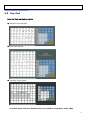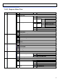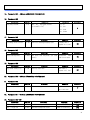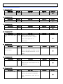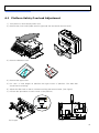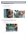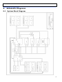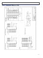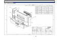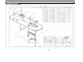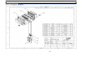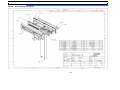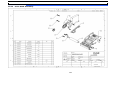
1
CL5000 Series Service Manual (English) Rev. 2014. 12. 11 1 Table of Contents 1. Proper Operation ................................................................................................................................................5 1.1 Introduction..............................................................................................................................................5 1.2 Model and Specification ..........................................................................................................................6 1.3 Environmental Conditions & Safety .......................................................................................................7 1.4 Leveling and Foot Location ....................................................................................................................8 1.5 Power Requirements ............................................................................................................................ 10 2. Classification .................................................................................................................................................... 11 3. 2.1 Scale Overview..................................................................................................................................... 11 2.2 Display and Indicators.......................................................................................................................... 12 2.3 Printer ................................................................................................................................................... 13 2.4 Communication ..................................................................................................................................... 14 2.5 Key Pad................................................................................................................................................. 15 Getting Started .............................................................................................................................................. 16 3.1 Sealing Method ..................................................................................................................................... 16 3.2 Installation of the Label Roll ................................................................................................................ 16 3.3. Turning Power On/Off ........................................................................................................................... 18 3.4 Program Menu and Tree ...................................................................................................................... 19 3.4.1 How to access the Program Mode ............................................................................................ 19 3.4.2. Program Menu Tree .................................................................................................................... 20 3.4.3 4. Calibration Menu Tree ............................................................................................................... 22 Calibration Mode ........................................................................................................................................... 23 4.1 Calibration............................................................................................................................................. 23 4.1.1. Span Calibration (Menu Code 8110) ........................................................................................... 24 4.2 4.1.2 Span/Zero Fine Adjust (Menu Code 8120) ............................................................................... 25 4.1.3 Capacity & Units (Menu Code 8130) ........................................................................................ 27 4.1.4 Gravity Constant (Menu Code 8140) ......................................................................................... 28 4.1.5 Percent Calibration (Menu Code 8150) ..................................................................................... 29 4.1.6 Linearity Adjust (Menu Code 8160) .......................................................................................... 30 4.1.7 Zero & Tare Setting (Menu Code 8170) ................................................................................... 31 Factory Setting (Menu Code 8180) ..................................................................................................... 32 4.2.3 A/D Initialize (Menu Code 8183) ............................................................................................... 32 4.2.4 Linearity Fine Adjust (Menu Code 8184) .................................................................................. 33 4.3.1 Clear Report (Menu Code 8211) ............................................................................................... 34 4.3.2 Clear All PLU (Menu Code 8212) .............................................................................................. 34 4.3.3 Clear All Table (Menu Code 8213) ........................................................................................... 34 4.3.4 Clear Report, PLU, Table (Menu Code 8214) .......................................................................... 34 4.5.1 Print Mode (Menu Code 8310) .................................................................................................. 36 2 4.6 4.5.2 Label/Ticket Size (Menu Code 8320) ....................................................................................... 36 4.5.3 Sensor Calibration (Menu Code 8330) ...................................................................................... 36 4.5.4 Sensor & Motor (Menu Code 8340) .......................................................................................... 36 4.5.5 Print Intensity (Menu Code 8350) ............................................................................................. 36 4.5.6 Adjust Feed Length (Menu Code 8360) .................................................................................... 37 4.5.7 Label Pre-print (Menu Code 8370) ........................................................................................... 37 4.5.8 Printer Initialize (Menu Code 8380) .......................................................................................... 37 Network Options .................................................................................................................................. 38 4.6.1 4.7 5. 6. 7. 8. Self Test ............................................................................................................................................... 38 4.7.1 Display Test (Menu Code 8510)................................................................................................ 38 4.7.2 A/D Test (Menu Code 8520) ..................................................................................................... 38 4.7.3 Keyboard Test (Menu Code 8530) ............................................................................................ 39 4.7.4 Chess Print (Menu Code 8540) ................................................................................................. 40 4.7.5 Printer Sensor Test (Menu Code 8550) .................................................................................... 40 4.7.6 Memory Information (Menu Code 8560) ................................................................................... 41 4.7.7 Firmware Version (Menu Code 8570) ....................................................................................... 41 Parameter ...................................................................................................................................................... 42 5.1 Factory Setting (para 800~999) .......................................................................................................... 42 5.2 Dealer Setting (para 500~799) ........................................................................................................... 47 Servicing & Parts Replacement ................................................................................................................... 68 6.1 Platform Safety Overload Adjustment................................................................................................. 69 6.2 Removing the Upper Case ................................................................................................................... 70 6.3 Main board Replacement...................................................................................................................... 72 6.4 Power Supply Replacement ................................................................................................................. 73 6.5 Load Cell & AD Converter Replacement ............................................................................................ 74 6.6 Print Assembly Replacement ............................................................................................................... 75 6.7 Display Replacement ............................................................................................................................ 76 6.8 Keyboard Replacement (With/Without breaking CAL seal ) .............................................................. 77 Installing Options ........................................................................................................................................... 78 7.1 Installing Ethernet Card ....................................................................................................................... 78 7.2 Installing Wireless Lan Card ................................................................................................................ 79 7.3 Installing Memory Expansion Card ..................................................................................................... 79 Update ............................................................................................................................................................ 80 8.1. 9. Enable Interface (Menu Code 8410) ......................................................................................... 38 Firmware update ................................................................................................................................. 80 Schematic Diagrams ...................................................................................................................................... 84 9.1 System Block Diagram ......................................................................................................................... 84 9.2 Connection Diagram ............................................................................................................................. 85 9.3 I/O Pin Connection ............................................................................................................................... 86 3 10. 11. 9.4 Main PCB .............................................................................................................................................. 87 9.5 A/D PCB ................................................................................................................................................ 91 9.6 Display PCB .......................................................................................................................................... 92 9.7 I/O PCB ................................................................................................................................................. 97 9.8 Printer I/O PCB .................................................................................................................................... 98 9.9 Slot PCB ................................................................................................................................................ 99 9.10 Expansion Memory PCB .................................................................................................................. 100 9.11 Wired LAN PCB ................................................................................................................................ 101 9.12 Wireless LAN PCB ........................................................................................................................... 102 9.13 CF Card PCB .................................................................................................................................... 103 Exploded Views ......................................................................................................................................... 104 10.1 Scale Assy (B,P,R-type) .................................................................................................................. 104 10.2 Scale Assy (H-type) ........................................................................................................................ 105 10.3 Body Assy (B,P,R-type) .................................................................................................................. 106 10.4 Body Assy (H-type) ......................................................................................................................... 107 10.5 Platform (B,P,R-type) ...................................................................................................................... 108 10.6 Main Frame (H-type) ....................................................................................................................... 109 10.7 I.O Cover (H-Type) ......................................................................................................................... 110 10.8 Upper Case ....................................................................................................................................... 111 10.9 Pole Display (R-type) ...................................................................................................................... 112 10.10 Pole Display (P-type) .................................................................................................................... 113 10.11 Printer Assembly............................................................................................................................ 114 10.12 Print Head Assembly ..................................................................................................................... 115 10.13 Cartridge ......................................................................................................................................... 116 10.14 Tray Assembly (B,P,R-type) ......................................................................................................... 117 10.15 Tray Assembly (H-type) ............................................................................................................... 118 10.16 LAN card ........................................................................................................................................ 119 Part List ..................................................................................................................................................... 120 11.1 Electronic.......................................................................................................................................... 120 11.2 Mechnical .......................................................................................................................................... 120 12. Revision ........................................................................................................................................................ 121 4 1. Proper Operation 1.1 Introduction Thank you for purchasing the CAS CL5000 Scale Printer. designed with many advanced features. The CL5000 Scale Printer has been With the high quality construction and the user-friendly menu driven programming we are confident that the CAS CL5000 Scale Printer will meet all of your most demanding requirements. The CL5000 utilizes a high speed thermal printer capable of print speeds up to 4 inches per second. It can print on both label and ticket materials. The label cartridge provides an easy method of replacing or installing labels. The CL5000 is capable of printing a variety of custom logos, nutritional information panels, ingredient messages and other in store advertising messages. Using the included software almost any custom label design is possible. Other features of the CL5000 include several selectable operation modes that enable you to control access to vital scale functions. through the software. Sales reports are available through the scale’s on-screen menus or Up to 144 quick look up or speed keys are available on the pole models and 106 on the bench model. The CL5000 has a “double click call” function that enables you to quickly recall speed keys without having to use a shift key. The CL5000 can be configured in an in-store network with up to 32 scales using either wired or wireless standard Ethernet protocols. Using this network configuration allows you to save time by managing and controlling scale programming and sales reporting from one central location. The scale’s operational speed in the network is the same as a stand alone machine because PLU and other data files are stored locally in each scale’s memory. The CL Works software package is included with each scale. PC’s using Windows 98/2000/XP operating systems. This software will operate on most Using the CL Works program enables you to have complete control over the CL5000 resulting in more accurate price control and programmed information. It also provides an excellent method of storing all scale data files as an emergency backup function. The CL Works software also includes a label design program that allows you to create, modify and store custom label formats and keyboard layouts. For proper operation and maintenance of your CL5000 please be sure to read the entire manual before use. A wide variety of supplies and accessories are available through your Authorized CAS Dealer. 5 1.2 Model and Specification Model CL5000 Series Capacity 15Kg 30Kg 30 lb 60 lb Interval 2g/5g 5g/10g 0.005lb/0.01lb 0.01b/0.02lb Max Tare -5.998Kg -9.995Kg -9.995lb -29.99lb 24 digit VFD + Graphic LCD Display Tare: 4 digit Weight: 5 digit Unit Price: 6 digit Total Price : 6 digit Weight: 5 digit Unit Price: 6 digit Total Price : 7 digit Zero Pass Range 1~50% (default 10%) Re-Zero Range 1~50% (default 2%) Overload Range Maximum Capacity to Maximum Capacity + 255d (default is set to Maximum Capacity +9d) A/D Conversion Rate Measurement type Platter type Key Speed Key Approx. 8/sec Load cell SUS B-Type PLU Key : 48, Function Key: 36 P-Type R-Type PLU Key : 96 (48 x 2) PLU Key : 72, Function Key: 36 PLU Key : 144 (72 x 2) Input Range 1~999999 3000 Default Ingredient (510 Characters) 1~999 999 User Defined Barcode Formats 1~99 99 Department 1~99 99 Tax Type 1~9 9 Group 1~99 99 99 Data Table Printer Type Printer Resolution Label Size Font Report Barcode Type Dimensions Max Default PLU Clerk 1~99 Discount 1~999999 99 Origin 1~499 499 Traceability 1~999 99 Slaughter House 1~999 99 Cutting Hall 1~999 99 Traceability Country 1~999 999 Label Format Default :45, User:20 Bitmap 14 14 Customer 1~99 99 Quantity Symbol 1~8 8 Scroll Message 1~9 9 Pay Type 0~8 8 Sales Message 1~99 99 Nutrifact 1~500 500 Tare Table 1~99 99 Currency 1~4 4 Direct Thermal Print 202 dpi Width: 40mm ~ 60mm, Length: 30mm ~ 120mm Offers various sizes of label format, e.g Small, Middle, Large Size, and on the label format, also offers various types of fonts, such as Italic, Bold, Underline, Through Line, Double Through line, Reverse, Shadow, Outline, etc. X1/X2, Z1/Z2, Scale, PLU, Misc. PLU, Group, Department, Hourly, Clerk Report EAN13, EAN13A5, EAN8, I2OF5, UPCA, UPC13, CODE39, CODE93, CODE128, CODABAR, B-Type 408 x 432 x 173 mm P-Type 408 x 493 x 542 mm R-Type 408 x 493 x 607 mm Tray : 380 x 244 mm 6 1.3 Environmental Conditions & Safety 1) Please avoid the following hostile conditions Temperatures below or exceeding: Ungrounded electrical outlet -10° C ~ 40° C (14° F ~ 104° F) Excessive vibration Unstable or flimsy surface Wind or fans functioning in direct contact Shared electrical outlet with weighing platform. Direct sunlight Dust or dirt High humidity Poor ventilation 2) Environmental Protection The scale should be installed in a dry and liquid free environment. When the scale is installed in a high humidity or wet-type environment, be sure to avoid spilling or spraying directly on any surface of the scale. 3) Personal Safety It is very important to be aware of personal safety whenever maintaining or operating this equipment. We have tried to place warning labels and other indicators at the actual location on the equipment where the danger is most likely to occur. Warnings and cautions that are necessary for the safe operation of the scale are contained in this manual. Please, make sure to read carefully ALL warnings and cautions before operating the scale. 4) Observe the following safety precautions Turn OFF and unplug the scale whenever you are changing the label roll or whenever working in the printer bay. The outlet that the scale is plugged into should be properly grounded. Whenever connecting or disconnecting ANY cables from the scale, be sure to hold the cables by the end connector. Failure to do so may cause a short circuit. Maintain a static-free work area. The outlet used must have the proper voltage ratings. 7 1.4 Leveling and Foot Location 1) Location This scale must be placed on a flat and stable surface. Please keep the scale away from the direct path of oscillating fans, ventilation systems, or strong drafts as these air disturbances can be picked-up by the scale’s very sensitive weighing platform and may cause incorrect weight readings. 1.1) General Foot Location Factory setting (Refer to Figure Below) 1.2) Short Case Foot Location Unscrew the foot and place in center hole for narrow locations. 8 2) Leveling If the scale is not properly leveled, please adjust the 4 adjustable legs at the bottom of the scale. Turn the legs clockwise or counterclockwise so as to center the bubble of the leveling gauge inside the indicated circle. Turning the adjustable legs counter-clockwise (viewed from top of scale) will lower that part of the scale. Turning the adjustable legs clockwise (viewed from top of scale) will raise that part of the scale. (See Fig.) 9 1.5 Power Requirements Power Source: AC 100~240V, 50/60Hz, 1.5A Power Consumption: Max 90W The CL5000’s Power inlet is located on the bottom of the scale. (Refer to Figure) RS232C Power Inlet Power Switch 1) The CL5000 is designed to be used almost anywhere in the world! Like many appliances of today, the CL5000 is designed with an automatically switching power supply. This allows operation when connected to an AC source from 100V to 240V at 50/60Hz with a 5% tolerance. NOTE: Please make sure that the power lines used for the CL5000 are dedicated lines with no high-noise devices such as compressors or motors on the same circuits. Also make sure that the wiring to the electrical socket is correct. If you are uncertain about the condition of your electrical wiring please contact a certified electrician. 2) Once you are sure as to the safety of the electrical line, make sure to ONLY plug the scale into a 3- pronged outlet. The third prong is a safety ground and an electrician should properly wire this if it is not correct or if you are unsure. Failure to do this CAN result in electrical shock from use of this or any electronic scale. 3) Do not use any 3-prong to 2-prong adapters or break off the third prong from the CL5000 power cord. The third prong is necessary and must be properly connected. 4) If you have any problems or questions regarding this matter, make sure to contact the CAS Service Department. 10 2. Classification 2.1 Scale Overview There are 3 different types of CL5000, Standard Type (B), Pole Types (R,P),and Hanging Type (H). ■ Standard Type ■ Pole Type R ■ Pole Type P ■ Hanging Type H 11 2.2 Display and Indicators The CL5000 has two different types of displays. A VFD type that displays the Tare Weight, Actual Weight, Unit Price and Total Price along with other scale information such as Stable, Auto mode, Save mode, PrePack mode, Discount (D/C), Shift and Data Transfer status with a tri-mark above each item. The other type of display that the CL5000 utilizes is a Graphic LCD (202 x 64 dot) display. The Graphic LCD is used to display Programming Menus, Scrolling Messages and other advertising promotions. ■ Type-I: 5/8/9 ■ Type-II : 4/5/6/6 ■ Indicators SYMBOLS DESCRIPTION ST (▼) Stable weight indicator ▶0◀ Zero weight indicator NET (▼) Net weight indicator kg Kilogram weighing indicator lb Pounds weighing indicator AUTO Print Mode indicator SAVE Auto clearing status indicator $/kg Unit Price per kilogram $/lb Unit Price per pound PREPACK Auto clearing status indicator DC (▼) Discount status indicator SHIFT (▼) Speed key shift status indicator TR Data transmission status indicator 12 2.3 Printer • Cartridge type print mechanism • High quality ROHM print head • Improved label drive utilizes 2 independent motors • Large compartment for 100mm label roll • Print speeds up 100 mm/sec. • Print Quality adjustments • Supports Die Cut Labels, Continuous Strip Labels and Thermal Receipt Paper ■ Label Specifications Outer Diameter of Roll : 100mm Inner Diameter of Roll : 40mm Width of Receipt Roll : 40, 50, 60mm Width of Label Roll : 60mm(Max) ■ Print Area Print Area : 56mm(Max) Width of Label : 60mm(Max) Length of Label : 120mm(Max) 13 2.4 Communication ■ Standard ① RS232C ② P/S 2 ■ Options ③ Ethernet cartridge ④ Wireless Ethernet cartridge Cash Drawer N/A ② P/S 2 ① RS232 ③ Ethernet Module ④ Wireless Ethernet Module 14 2.5 Key Pad Note: Key Pads may vary by country ■ Standard Type Keypad ■ Pole Type Keypad ■ Hanging Type Keypad * Function Keys and User Defined keys are available using Menu Code 1880 15 3. Getting Started 3.1 Sealing Method 3.2 Installation of the Label Roll To install the label roll follow the directions in this section: 1) Press the ON/OFF key and make sure that the display is completely off. Open the printer’s side- access panel. (See fig.1) 2) Release the Print Head (fig 2) 16 3) Remove Label Cartridge (fig. 3) 4) Remove Rewind Paper Lock and Roll Cover from the Cartridge (fig. 4) 4 5) Place the label roll in the cartridge (fig. 5) 5 6) Route labels through the cartridge and secure them on the label take up spool (fig 6) 7) Place label cartridge back into scale (fig 7) 8) Press the FEED key. NOTE: For auto label calibration press FEED key two or three times * If label position is not correct, check the following: a. Label size (Label Setting Menu Code 1732) b. Feed Adjustment (Adjust Feed Length Menu Code 1736) c. Sensor Calibration (Sensor Calibration Menu Code 1733) 17 3.3. Turning Power On/Off When the scale is turned on the display will show a count down (9~0) for self testing. 9999 999999 99999999 The following is a list of the self test functions that are performed during the countdown. Buzzer On Initial Port,Timer,UART(AD),CPLD,PrinterDriver,RTC Printer Driver Start Start Timer Buzzer Off Initial Flash Check,Set UART (AD) Baudrate LCD,Display,Key,PS2 VFD “999999” Init Serial, Check Caption Data VFD “888888” Init ADM,Check Memory Map VFD “777777” Check Network Parameter, Load Global Parameter,Load Service Type VFD “666666” Check Network Flag,CAL mode VFD “555555” - VFD “444444” Init Ethernet Module VFD “333333” Init PLU_Data VFD “222222” Key Error Check -> Buz,Buz : VFD “111111” Load Label Default, CheckAdInitStatus VFD “000000” Check Password,Logging BOOTTIME,NETSTART Command Queue Init 18 3.4 Program Menu and Tree 3.4.1 How to access the Program Mode Note: You can directly access the individual programming menus by entering the Menu Code and pressing the MENU key. The 2 numbers at the top right (1/3) are there to help you navigate through the menu items. The number to the left of the slash is the current page or screen number and the number to the right of the slash indicates the total number of pages or screens for that menu item. You can use the PAGE UP and PAGE DOWN keys to navigate from page to page or you can use the Arrow keys to navigate 1 line at a time. (Screen 1 of 3) 1000 PROGRAM MODE 1. PLU 2. PLU Data Table I. 3. PLU Data Table II. Menu code Selectable menu. (1/3) If you want to select PLU simply press 1. If you press “Pg Dn” key, you can see other menu screens as below. PROGRAM MODE 1. PLU 2. PLU Data Table I. 3. PLU Data Table II. (1/3) PROGRAM MODE 7. Print 8. Scale Configuration 9. Network Communication (3/3) PROGRAM MODE 4. Store Data Table 5. Global Setting 6. Report (2/3) 19 3.4.2. Program Menu Tree CODE Menu CODE Sub Menu 1100 PLU 1110 1120 1130 1140 1200 1300 1400 1500 PLU Table1 PLU Table2 Store Data Table Global Setting Change Price New/Edit Discount Management 1150 1160 1170 List Speed Key Sample Printing 1210 1220 1230 1240 Department Group Tax Rate Sales Message 1250 1260 1270 1280 Origin Barcode Tare Unit Symbol 1310 1320 1330 1340 Ingredient Nutrition Facts Traceability Country 1350 1360 Slaughter House Cutting Hall 1410 Store 1420 1430 Customer Scroll Message 1440 Currency 1510 1520 1530 Label Format Barcode Discount 1540 Tax CODE Sub Menu 1131 1132 1133 New/Edit List Delete 1137 1138 1141 1142 Copy Delete 1143 Move 1144 1145 Select PLU Items PLU Sale Count 1431 1432 1433 Configuration Edit Scroll Message List Scroll Message Delete by PLU(DC) Delete by Dept(DC) 1139 Delete All 1147 1148 1149 Delete by PLU No. Delete by Dept. No. Delete All 1531 Priority Setting 1532 1533 1534 1541 1542 Weight Discount Count Discount PCS Discount Set Global Tax Global Tax No. 20 1600 Report 1610 1620 1630 1700 1800 Printing Scale Config X1 Report Z1 Report X2 Report 1640 1650 Z2 Report Clear All 1710 1720 Print inhibit Markdown 1730 H/W Setting 1740 1750 1760 Serial Number Format Addup Total Ticket 1810 Sale Mode 1820 Operation Mode 1830 1840 1850 Department Date/Time User/Security Configuration 1860 1870 1880 Test Scale Parameter 1611 1612 1613 1614 1615 Scale PLU Misc. PLU Group Department 1616 1617 Hourly Clerk 1631 1632 1633 Scale PLU Misc. PLU 1634 1635 1636 1637 Group Department Hourly Clerk 1731 1732 1733 1734 1735 1736 Print Mode Label/Ticket Size Sensor Calibration Motor & Sensor Print Intensity Adjust Feed Length 1737 Label Preprint 1761 1762 Select Ticket Item Select List Item 1763 Select Ticket Font Size 1851 1852 1853 1854 New/Edit User Change Password List User Delete User 1855 1856 1861 1862 1863 1864 Config Permission Clerk Key Display A/D Keypad Printer 1865 1866 1867 1868 1871 1872 Printer Sensor Memory Information Firmware Version Communication Display Printing 1873 1874 Sale setup Clerk Logout Function Key Define 21 1900 Communication 1910 Network Setting 1911 1912 1913 1914 1915 Service Type DHCP IP Remote IP RS232C 1916 1917 WLAN Setting WLAN Config 1920 Application 1930 Scale Lock/Unlock 1940 Check Scale 1950 Backup to scale 3.4.3 Calibration Menu Tree CODE Menu CODE Sub Menu 8100 Calibration 8110 8120 8130 8140 8150 Span Calibration Span/Zero Fine Adjust Capacity & Units Gravity Constant Percent Calibration 8160 8170 8180 Linearity Adjust Zero & Tare Setting Factory Setting 8200 8300 System Options Printer Hardware 8210 Clear Memory 8220 Scale Type 8310 8320 8330 8340 8350 Print Mode Label/Ticket Size Sensor Calibration Sensor & Motor Printer Intensity 8360 8370 8380 Adjust Feed Length Label Pre-print Printer Initialize 8400 Network Options 8410 Enable Interface 8500 Self Test 8510 Display Test 8520 8530 8540 8550 8560 8570 A/D Test Keyboard Test Printer Test Printer Sensor Test Memory Information Firmware Version 8580 Cash Drawer Test 8590 Communication Test 8600 [Parameter Setting Mode] 8600 Parameter Setting CODE Sub Menu 8181 Digital Filtering 8182 A/D Hardware Setting 8183 A/D Initialize 8184 Linearity Fine Adjust 8185 Hysteresis Calibration 8186 Creep Setting 8187 A/D Firmware 8211 Clear Report 8212 Clear All PLU 8213 8214 Clear All Table Flash All Clear 22 4. Calibration Mode 4.1 Calibration (Calibration MENU -> 1. Calibration) Execute Weight Calibration and A/D related settings (Should be performed by an Authorized CAS Dealer Only) Lift the platter and remove the Calibration Seal. (CAUTION: Lift the platter from the right side first and then unlock the left side. Refer to the figure) To access Calibration Mode: Turn ON Main Power Switch while pressing the CAL button. (Refer to figure below) NOTE: For Hanging type: Remove the bottom cover. First page of Calibration mode 8000 CAL ModE CALIBRATION MODE 1. CALIBRATION 2. SYSTEM OPTIONS 3. PRINTER HARDWARE (1/2) 23 4.1.1. Span Calibration (Menu Code 8110) (Calibration MENU -> 1. Calibration -> 1. Span Calibration) Note: Proper Calibration of the CL5000 requires the use of government certified weights. Make sure you have the correct amount of weight for the capacity that the scale is going to use. (Ex: 30lbs of weight for a 30lb capacity scale.) Max Capacity of the CL5000 is set in Menu 1830. The display will prompt you for the amount of weight needed based on the scale configuration settings. 8100 ModE CAL CALIBRATION 1. SPAN CALIBRATION 2. SPAN/ZERO FINE ADJUST 3. CAPACITY & UNITS (1/3) ① Select “Span Calibration” ULoad 5481 5481 ZERO CALIBRATION (1/2) - REMOVE ALL WEIGHT. - PRESS PRINT WHEN READY. ② Remove all weight from platter and press “PRINT” Display will show “Wait4”, 3, 2 ,1 and then “Wait0” then the SPAN CALIBRATION Display. LoAd 5481 0 ③ Place the maximum capacity on the platter. LoAd 34475 SPAN CALIBRATION (2/2) - PLACE 15. LBS ON THE PLATTER. - PRESS PRINT WHEN READY. (Menu 8130 sets the max capacity for calibration.) 39962 SPAN CALIBRATION (2/2) - PLACE 15 LBS ON THE PLATTER - PRESS PRINT WHEN READY. ④ Press “PRINT” Display shows “Wait4”, 3, 2, 1 and then Wait0” then returns to the Main Calibration Menu. 8100 CAL ModE CALIBRATION 1. SPAN CALIBRATION 2. SPAN/ZERO FINE ADJUST 3. CAPACITY & UNITS (1/3) 24 Error Message * If the platter is unstable during the Calibration process, the following error message will appear. WAit0 2776 2776 Cal Error – Unstable (0x01) Press Any Key * If the Calibration weight was too much or not enough, the following error message will appear. - Calibration weight limits can be re-adjusted by menu 8182 “Cal Zero(Span) Max(Min) Range” WAit0 1027 1027 Cal Error – Range Over (0x07) Press Any Key * If an A/D failure is detected during the Calibration process the following error message will appear. Please check the connector between the main board and the controller board. WAit0 1027 1027 Cal Error – Wrong ADM (0xff) Press Any Key 4.1.2 Span/Zero Fine Adjust (Menu Code 8120) (Calibration MENU -> 1. Calibration -> 2. Span/Zero Fine Adjust) This mode is for fine tuning of Span and Zero settings after performing a SPAN Calibration if necessary. 8100 CAL ModE CALIBRATION 1. SPAN CALIBRATION 2. SPAN/ZERO FINE ADJUST 3. CAPACITY & UNITS (1/3) SPAN/ZERO FINE ADJUST ZERO:[ 10730] SPAN:[ 88133] (1/1) ① Select menu “Span/Zero Fine Adjust” 8120 ⓐ Menu Code 0 ⓑ Internal Value 0 ⓒ External Value (Weight) ⓓ Pure setting value of Zero & Span * If ⓒ is not set to zero press “ ZERO” key. Value ⓓ will update. 25 ② Put Max. Capacity weight on the platter 8120 60012 15005 SPAN/ZERO FINE ADJUST ZERO:[ 10730] SPAN:[ 88133] (1/1) ③ Use ◀ ▶ key for fine adjust. * Insert setting value by using the cursor keys (for the fine adjustment) “▶” Increases Span value “ⓓ” to decrease Internal value “ⓑ” “◀” Decreases Span value “ⓓ” to increase External value “ⓑ” - Internal value 60012 needs to change 60000 Press 8120 ▶ X 12 Times to decrease internal value. 60000 15000 SPAN/ZERO FINE ADJUST ZERO:[ 10730] SPAN:[ 88145] (1/1) * Insert setting value by number key pad - Set Span value: use curser key to highlight span value. - Type estimate value using number key then press “TEST” key for results # This process may take several times to set 60000. During this process Max Capacity weight is needed for best result. Ex) Input “88145” by keypad and press “TEST” key 8120 60000 15000 SPAN/ZERO FINE ADJUST ZERO:[ 10730] SPAN:[ 88145] (1/1) 26 4.1.3 Capacity & Units (Menu Code 8130) (Calibration MENU -> 1. Calibration -> 3. Capacity & Units) This mode is used to set the CL5000’s Weighing Units, Capacity, Interval, and Cal Unit. CAUTION: The Capacity & Units Setting should be made prior to performing the Span Calibration procedure. If the Capacity & Units setting is changed you must perform a Span Calibration again. Do not change setting after Span calibration. 1 Option Setting Value Weighing Unit Setting Scale Unit 0 : kg 1 : lb 2:g 2 Capacity Setting Scale Max Capacity 1 : 15 kg / 30 lb 2 : 30 kg / 60 lb 3 Interval Setting Usage of Multi-interval 0 : Single Interval 1 : Dual Interval 4 Cal Unit Setting Calibration Weighing unit 0 : kg 1 : lb * This setting uses in Span Calibration, Percent Calibration, Linearity Adjust. 8130 CAL ModE CAPACITY & UNITS (1/2) WEIGHING UNIT:[ 1 ] 0)KG 1)LB 2)G CAPACITY :[ 1 ] 1) 30LB INTERVAL :[ 0 ] 0)SINGLE 1)DUAL CAPACITY & UNITS CAL UNIT :[0] 0)KG 1)LB (2/2) 27 4.1.4 Gravity Constant (Menu Code 8140) (Calibration MENU -> 1. Calibration -> 4. Gravity Constant) CL-5000 scale allows you to calibrate for any country. You can set the gravity constant data according to the country. In case of full re-calibration set the factory gravity first and then local area gravity code. (For span calibration Local gravity value is automatically matched with Factory gravity value) 8140 CAL ModE GRAVITY CONSTANT (1/1) FACTORY GRAVITY :[9.8024] LOCAL GRAVITY :[9.7814] Use the following table to determine the proper G-Constant for your area. Country City G-Constant Country City G-Constant Argentina Buenos Aires 9.7979 Mexico Mexico City 9.7799 Australia Sydney 9.7979 Morocco Rabat 9.7964 Austria Vienna 9.8099 Netherlands Amsterdam 9.8129 Belgium Brussels 9.8114 New Zealand Wellington 9.8039 Belize Manamah 9.7904 Norway Oslo 9.8189 Bolivia La Paz 9.7844 Panama Panama City 9.7814 Brazil Brasilia 9.7889 Peru Lima 9.7829 Canada Montreal 9.8069 Philippines Manila 9.7844 Ottawa 9.8069 Poland Swider 9.8159 Toronto 9.8054 Portugal Lisbon 9.8009 Vancouver 9.8099 Rumania Bucharest 9.8054 Check Republic Prague 9.8114 Saudi Arabia Riyad 9.7904 Chile Santiago 9.7979 Scotland Stockholm 9.8189 China Hong Kong 9.8099 Singapore Singapore 9.7814 Colombia Bogota 9.7799 South Africa Johannesburg 9.7919 Costa Rica San Jose 9.7829 Spain Madrid 9.8024 Cypress Nicosia 9.7979 Switzerland Bern 9.8084 Denmark Copenhagen 9.8159 Taiwan Taipei 9.7904 Ecuador Quito 9.7724 Tunisia Tunis 9.7799 Finland Helsinki 9.8189 Turley Ankara 9.8024 Germany Dusseldorf 9.8129 Uruguay Montevideo 9.7964 Great Britain London 9.8144 USA Anchorage 9.8189 Greece Athens 9.8009 Atlanta 9.7964 28 Guatemala Guatemala 9.7844 Boston 9.8039 Hungary Budapest 9.8069 Chicago 9.8024 Indonesia Djakarta 9.7814 Dallas 9.7949 Iraq Baghdad 9.7964 Detroit 9.8039 Japan Mishima 9.7979 Los Angeles 9.7979 Korea Seoul 9.7994 New York 9.8024 Kuwait Kuwait 9.7919 Philadelphia 9.8024 Lebanon Beirut 9.7964 San Francisco 9.7994 Mauritius Port Louis 9.7859 Caracas 9.7829 NOTE: Venezuela The G-Constant is the acceleration of gravity in meters per second per second. 4.1.5 Percent Calibration (Menu Code 8150) (Calibration MENU -> 1. Calibration -> 5. Percent Calibration) When you don’t have the maximum weights for calibration, the Percent Calibration allows you to set the amount of weight you will use to calibrate the scale. 8100 CAL CALIBRATION 4. GRAVITY CONSTANT 5. PERCENT CALIBRATION 6. LINEARITY ADJUST (2/3) (1/1) ModE PERCENT CALIBRATION USE WEIGHT : [15] LB FULL CAPA WEIGHT: 30.00 LB 5481 ZERO CALIBRATION(1/2) - REMOVE ALL WEIGHT. - PRESS PRINT WHEN READY. ModE ① Select Percent Calibration. 8150 CAL ② For 15lb weight, input “15” and press “print” ULoAd 5481 ③ Remove all weight from the platter and press “PRINT”, then “Wait4~Wait0” will display. LoAd 0 10731 SPAN CALIBRATION (2/2) - PLACE 15 lb ON THE PLATTER. - PRESS PRINT WHEN READY. ④ Put 15lb on the platter then press “PRINT” after “Wait4~Wait0” scale will return to CAL Menu. 29 4.1.6 Linearity Adjust (Menu Code 8160) (Calibration MENU -> 1. Calibration -> 6. Linearity Adjust) You can fine adjust the mid-range weight reading for a more precise calibration. 8100 CAL ModE CALIBRATION 4. GRAVITY CONSTANT 5. PERCENT CALIBRATION 6. LINEARITY ADJUST (2/3) LINEARITY ADJUST USE WEIGHT :[ 15] lb FULL CAPA WEIGHT : 30.00 lb (1/1) ZERO CALIBRATION - REMOVE ALL WEIGHT. - PRESS PRINT WHEN READY. (1/3) ① Select Linearity Adjust. 8160 CAL ModE ② For 15lb weight, input “15”key and press “print” ULoAd 5501 5501 ③ Remove all weight from the platter and press “PRINT”, after “Wait4~Wait0” display shows Mid 0 5501 MID CALIBRATION (2/3) - PLACE 15 LB ON THE PLATTER. - PRESS PRINT WHEN READY. ④ Place 15lbs on platter and press “PRINT” after “Wait4~Wait0” display will show LoAd 17243 22745 SPAN CALIBRATION (3/3) - PLACE 30.00 LB ON THE PLATTER. - PRESS PRINT WHEN READY. ⑤ Put 30lbs on the platter and then press “PRINT” after “Wait4~Wait0” display will show 8100 CAL ModE CALIBRATION 4. GRAVITY CONSTANT 5. PERCENT CALIBRATION 6. LINEARITY ADJUST (2/3) 30 4.1.7 Zero & Tare Setting (Menu Code 8170) (Calibration MENU -> 1. Calibration -> 7. Zero & Tare Setting) CAUTION: This Setting is part of (OIML, NTEP, etc) regulation must be setting by the local restriction. You can set the ZERO, TARE at acceptable range and maximum display range. 8170 CAL ModE ZERO & TARE SETTING (1/3) INIT-ZERO RANGE(%): [ 10] REZERO RANGE(%) : [ 2] OVERLOAD RANGE(D): [ 9] ZERO & TARE SETTING (2/3) ACCUMULATION TARE(Y/N) : [ N ] SUBTRACTION TARE(Y/N) : [ N ] GROSS ZERO MARK(Y/N): [ Y ] ZERO & TARE SETTING (3/3) NET ZERO MARK(Y/N) : [ N ] GROSS ZERO-TRACKING(Y/N) : [ Y ] NET ZERO TRACKING(Y/N) : [ N ] Init-Zero range Before entering the Sales Mode the Calibrated A/D value and current A/D value are compared. These values need to be in an acceptable range for the CL5000 to function properly. The CL5000 will not operate correctly if there is any weight on the platter. Re-zero Range (%) During normal usage, zero range might become unstable. This could be caused by the platter or other environmental conditions. You can set the allowed percent (%) range for zero display. (OIML regulation restricts 2% of maximum weight range can be used) Overload Range (d) You can set the maximum overload range. For example, [9] set as 30.09 lbs (.01x[9]=.09lbs). If the weight is over 30.09 lbs the overload message will appear. Accumulation (Y/N) Tare weights can be accumulated. This is useful when adding packages of different types. Subtraction(Y/N) Allows you to set a different Tare value but only if the new tare value is less than the first value. 31 Gross Zero Mark(Y/N) The real weight value is 0(Gross Weight=0) display will indicate “▼” on the gross weight NOTE: * Gross weight will display as total weight. (Tare setting does not effect) * Net weight is remain value of Tare weight. * If Tare setting is set as “N” the gross weight and net weight value is same. Net Zero Mark(Y/N) When Tare weight is set to zero, Zero mark will display. In other words Net Weight is zero. Gross Zero-Tracking(Y/N) You can set Zero-tracking while Gross Zero is 0. Factory setting is “Y”. Net Zero-Tracking(Y/N) You can set Zero-tracking while Net zero is 0. Factory setting is “N”. 4.2 Factory Setting (Menu Code 8180) (Calibration MENU -> 1. Calibration -> 8. Factory Setting) This setting A/D’s advanced setting only for factory primary setting. 4.2.3 A/D Initialize (Menu Code 8183) (Calibration MENU -> 1. Calibration -> 8. Factory Setting -> 3. A/D Initialize) 8183 CAL ModE A/D INITIALIZE Are You Sure?(Y/N) (1/1) :[N] CAUTION: Must record setting values before Selecting [Y]. This will set the scale first default setting 32 4.2.4 Linearity Fine Adjust (Menu Code 8184) (Calibration MENU -> 1. Calibration -> 8. Factory Setting -> 4. Linearity Fine Adjust) ① Selecting“LinearityFineAdjust” 8184 ⓐ Menu Code 0 ⓑ Internal value 0 LINEARITY FINE ADJUST ZERO:[ 10730] MID :[ 36532] SPAN:[ 88145] ⓒ External V.(weight) (1/1) ⓓ Real value of Zero & Span NOTE: You can set 0 by pushing “ZERO” This will update new Zero value. ② Using the weight value entered in MENU 8160, place 15lbs (MAX=30lbs) on the platter. 8184 20005 5002 LINEARITY FINE ADJUST ZERO:[ 10730] MID :[ 36537] SPAN:[ 88145] (1/1) ③ Using cursor key for fine adjust. * How to use cursor key “▶” Increase Span value(ⓓ) to reduce internal (ⓑ)value “◀“ Decrease Span value(ⓓ) to increase internal (ⓑ)value - Setting Mid value press “▼”key - Internal value 20005 to change 20000 press “▶” 5times. * How to input setting value - Use cursor key to change mid value. - Insert “36537” then press “TEST” 8184 60000 15000 LINEARITY FINE ADJUST Zero:[ 10730] Mid :[ 36537] Span:[ 88145] (1/1) ④ Also change Span value with cursor key. ⑤ Press “SAVE” to save and exit. 33 4.3 Memory Clear (Calibration MENU -> 2. System Options -> 1. Clear Memory) The CL5000’s memory can be cleared individually, item by item, or it can be cleared all at once based on the following options. 8000 CAL ModE CALIBRATION MODE 1. CALIBRATION 2. SYSTEM OPTIONS 3. PRINTER HARDWARE (1/2) SYSTEM OPTIONS 1. CLEAR MEMORY 2. SCALE TYPE (1/1) CLEAR MEMORY 1. CLEAR REPORT 2. CLEAR ALL PLU 3. CLEAR ALL TABLE (1/2) ① Select System Options 8200 CAL ModE ② Select Clear Memory 8210 CAL ModE CLEAR MEMORY (2/2) 4. CLEAR REPORT, PLU, TABLE 4.3.1 Clear Report (Menu Code 8211) (Calibration MENU -> 2. System Options -> 1. Clear Memory -> 1. Clear Report) The Clear Report Menu item will clear only the Sales Data stored in the scale. 4.3.2 Clear All PLU (Menu Code 8212) (Calibration MENU -> 2. System Options -> 1. Clear Memory -> 2. Clear All PLU) The Clear All PLU Menu item will clear ALL PLU Data and ALL Discount Data. 4.3.3 Clear All Table (Menu Code 8213) (Calibration MENU -> 2. System Options -> 1. Clear Memory -> 3. Clear All Table) The Clear All Table Menu item will clear ALL Table Data except for the PLU and Discount. This includes Department names, Sales Messages, Ingredients, Nutrifacts, etc. 4.3.4 Clear Report, PLU, Table (Menu Code 8214) (Calibration MENU -> 2. System Options -> 1. Clear Memory -> 4. Clear Report, PLU, Table) The Clear Report, PLU, Table Menu item will clear all Sales, PLU, Discount and Table Data from the scale in one step. 34 4.4 Scale Type Menu Code 8220 (Calibration MENU -> 2. System Options -> 2. Scale Type) This Menu item is used to select the proper scale model. The possible models are: 1. Standard Type (CL5000-B) 2. Pole Type (CL5000-R or CL5000-P) 3. Hanging Type (CL5000-H) 4. Self Service Type CAUTION: Selecting the wrong scale model can affect the keyboard layout and cause improper operation of the CL5000. Please make sure to select the type that matches your CL5000. 4.5 Printer Hardware No. Sub-menus Description 1 Print Mode Select label, ticket, continuous label mode. 2 Label / Ticket Label Mode: “Width(60)”, “Height(40)” and “Gap length(2)” Size Ticket mode: “Width(60)”, “Feed(20)” and “End Margin(30)” Continous Label: “Width(60)”, “Feed(40)” and “End Margin(30)” * ( ) are default value. 3 Sensor Enter the “Gap(128)” and “Peel(128)” values for printing sensor Calibration calibration. * The values in ( ) are default. * If you press “TEST” key, Gap and Peel values are adjusted automatically. * In case of Ticket mode, Gap value is not saved. 4 Sensor & Motor Setting Peel-off sensor, Rewind Motor, Label Paper type. 5 Print Intensity Sets the Print Intensity or Print darkness.. 6 Adjust Feed Set adjusting values of feed length. Length This value can be from -200 to +200. You can change sign(+,-) by pressing ZERO key. * Pressing “TEST” key automatically feeds to adjust the feed length. 7 Label Pre-print You can set preprint length. 8 Printer Initialize You can reset printer. 35 4.5.1 Print Mode (Menu Code 8310) (Calibration MENU -> 3. Printer Hardware -> 1. Print Mode) Press “1” to get into “PRINT MODE.” You can select “0” for Label mode, “1” for Ticket mode or “2” for Continuous Label mode. Press “PRINT” to save current selection. 4.5.2 Label/Ticket Size (Menu Code 8320) (Calibration MENU -> 3. Printer Hardware -> 2. Label/Ticket Size) You can input “Width,” “Height,” “Gap Length” of label manually. “TEST” key will automatically measures current label. * Case of ticket mode “TICKET SIZE” will display and “TEST” key will not function. 4.5.3 Sensor Calibration (Menu Code 8330) (Calibration MENU -> 3. Printer Hardware -> 3. Sensor Calibration) You can input “Gap,” “Peel,” “Out of Paper” manually. “TEST” key will automatically feed the label several times to calculate the measurement. * For Ticket mode, display will be same except “Gap” value. (This value will not save) 4.5.4 Sensor & Motor (Menu Code 8340) (Calibration MENU -> 3. Printer Hardware -> 4. Sensor&Motor) In this menu you can enable or disable the PEEL OFF Sensor, GAP Sensor or Label Take Up/Rewind Motor. Press “4” to get into “SENSOR&MOTOR”. You can select [Y], [N] for “ACTIVE PEEL-OFF,” “ACTIVE REWIND MOTER,” AND “LABEL PAPER.” * For Ticket mode display will be same. Only “ACTIVE PEEL-OFF” can be set. * For Ticket mode Rewind-Motor and Label paper setting will not display. 4.5.5 Print Intensity (Menu Code 8350) (Calibration MENU -> 3. Printer Hardware -> 1. Clear Memory) The Print Intensity Menu allows you to adjust the darkness of the print. The adjustment value is from “0” to “20” with “0” being the lightest and 20 being the darkest. Press “TEST” to issue a test label or ticket. 36 4.5.6 Adjust Feed Length (Menu Code 8360) (Calibration MENU -> 3. Printer Hardware -> 6. Adjust Feed Length) User may enter any value of the feed alignment from “-200” to “+200”. Press “ZERO” to toggle sign. Press “TEST” to test feed or “ENTER” to save current “FEED Length value. * 1pixel = 0.125mm , 8pixel = 1mm Ex) Value “+80” will feed 10mm more Value “-40” will feed 5mm less 4.5.7 Label Pre-print (Menu Code 8370) (Calibration MENU -> 3. Printer Hardware -> 3. Label Pre-print) User may enter “Y(Yes)” or “N(No)” to select Preprint mode and any value of the preprint length from “0”mm to “10”mm. Press “TEST” to test preprinting. 4.5.8 Printer Initialize (Menu Code 8380) (Calibration MENU -> 3. Printer Hardware -> 8. Printer Initialize) Initialize printer setting. 37 4.6 Network Options 4.6.1 Enable Interface (Menu Code 8410) (Calibration MENU -> 4. Network Options -> 1. Enable Interface) You can set usage of I/O interface. 8410 CAL ModE ENABLE INTERFACE Ethernet(TCP/IP) :[Y] (1/1) 4.7 Self Test 4.7.1 Display Test (Menu Code 8510) (Calibration MENU -> 5. Self Test -> 1. Display Test) Selecting 1 will start Display test, press any key to stop and exit. 4.7.2 A/D Test (Menu Code 8520) (Calibration MENU -> 5. Self Test -> 2. A/D Test) 8520 0 8333 A/D TEST (1/1) Normalized AD(AD1) – C1 value You can select A/D level “0”~“5” to test. NOTE: You can set ZERO temporarily within each level. Exiting the menu will not keep zero value. Key No. 0 Name Weight – External value Description kg or lb (◀ : kg, ▶ : lb) 1 Normalized(Zeroing) A/D Internal count (60,000). Calibration Zero - A/D 2 Normalized A/D Internal count (60,000) 3 Unit Factorized A/D Unit Factor applied A/D value 4 Linearized A/D Linear incising A/D value 5 Filtered Raw A/D Filtered Raw A/D 38 4.7.3 Keyboard Test (Menu Code 8530) (Calibration MENU -> 5. Self Test -> 3. Keyboard Test) You can test keyboard by pressing. 8530 CAL ModE KEYBOARD TEST (1/1) Raw Code:[006C] Menu Key Flag::[0] Cnv.Code:[0003] Mode:[1] KEYBOARD TEST (1/1) Raw Code:[006C] Menu Key Flag:[0] Cnv.Code:[0003] Mode:[1] [ESC]=Exit,[PRINT]=Mode Change KEYBOARD TEST (1/1) Raw Code:[006C] Menu Key Flag::[0] Cnv.Code:[0003] Mode:[1] [0]=Sale, [1]=Program Press any keys to test Row Code and Conversion Code. * Raw Code is location of key. (Upper left corner is 1. For Bench Type starts with 22) * Conversion Code is function Code which has different code other then Raw Code. * Menu Key Flag will set as 1 when “MENU” and other key is pushed same time. * Press ESC will exit the test or change key mode. - ESC + ESC : End of test - ESC + PRINT key to change Mode Mode 0 : Sale Mode Mode 1 : program Mode 39 4.7.4 Chess Print (Menu Code 8540) (Calibration MENU -> 5. Self Test -> 4. Chess Print) Self Test Menu screen, press the 4 key for Printer Test. The scale will then print a TPH (Thermal Print Head) test label. This label print checker pattern helps to find problems with the TPH. You should clean the TPH before you try this procedure. procedure for cleaning the TPH. Follow the maintenance The following examples show some of the problems that can occur. 1 2 There are several things that this printout sample can reveal: 1. The platen roller may be dirty, have something stuck to it or be physically damaged. 2. This is a clear indication that the Thermal Head has been damaged or has failed. The Thermal Head should only be replaced by an Authorized CAS Dealer. If you need to replace the TPH, please contact the CAS Service Department. 4.7.5 Printer Sensor Test (Menu Code 8550) (Calibration MENU -> 5. Self Test -> 5. Printer Sensor Test) You can test PEEL-OFF Sensor and Head Up Sensor in real time. 8550 CAL ModE PRINTER SENSOR TEST Peel-off :[UNLOCK ] Head-up :[CLOSE ] PRINTER SENSOR TEST Gap :[ 63] Peel:[114] (1/2) (2/2) 40 Test Items Description 1 Peel-off Checks the Peel-Off Sensor 2 Head-up Checks Thermal Head Up Sensor 3 Gap Displays Label Gap Sensor Value 4 Peel Displays Peel-Off Sensor Value 4.7.6 Memory Information (Menu Code 8560) (Calibration MENU -> 5. Self Test -> 6. Memory Information) The CL5000 Memory can be expaned up to 6MB Memory Status is displayed by using “0” and “X” “0” represents memory that is installed (in 1MB increments) “X” represents vacant memory space. 8560 CAL ModE MEMORY INFORMATION 012345 Chip Status :[00XXXX] Total Flash Size(MB) : 2 (1/1) 4.7.7 Firmware Version (Menu Code 8570) (Calibration MENU -> 5. Self Test -> 7. Firmware Version) This menu item reads the current firmware versions in the scale. There are 2 pages of information that can be viewed by pressing the PG Up and PG Down keys. 8570 CAL ModE DEV DESCRIPTION #1 Scale Main F/W #2 A/D Module F/W #3 Ethernet VERSION V1.35.2 V1.12 LAN 2.01 DEV DESCRIPTION #4 Caption (V1.35) #5 Data #6 Scale Boot VERSION V2.0 V1.5 VFF.FF #1 Scale Main Firmware Version #2 A/D Module Firmware Version #3 Ethernet Version #4 Caption Version #5 Data Version #6 Scale Boot Version 41 5. Parameter 8600 CAL Mode PARAMETER SETTING Function code : [501] Ride Second Position (1/1) The Parameter Setting Menu allows you to input Function Codes to change the CL5000’ s predefined settings. These settings determine how the scale operates and should only be changed if you are certain about the effect they will have on scale operations. In some cases these settings should not be changed without first checking with the local government agency. There are two levels of Parameter Settings, Factory and Dealer. The Factory Settings are numbered 800 ~ 899 and can only be accessed through the Calibration Mode. The Dealer Settings are numbered 500 ~ 799 and can be accessed either through the Calibration Mode or by using the System Password from the normal Programming Menu. 5.1 Factory Setting (para 800~999) 1. Parameter 801 ~ 808 are UNDEFINED PARAMETERS 2. Parameter 809 MESSAGE VALUE CONTENT Weight Decimal Point 0~10 Define weight position of decimal point VALUE CONTENT REMARK DEFAULT 2 3. Parameter 810 MESSAGE Price Decimal Point 0~10 REMARK Define price position of decimal point DEFAULT 2 4. Parameter 811 ~ 830 are UNDEFINED PARAMETERS 5. Parameter 831 MESSAGE Select Initial Screen VALUE 0~3 CONTENT Select Initial start message on display REMARK DEFAULT 0: Chess 1: Check List 2 : Version 2 3: Logo 42 6. Parameter 832 MESSAGE Use Serial Out VALUE CONTENT Y/N REMARK Transmit initial start by serial port. Yes= USE No= NO USE DEFAULT N 7. Parameter 833 MESSAGE Use last using time VALUE CONTENT Y/N REMARK Display last usage time. Yes = USE No = NO USE DEFAULT N 8. Parameter 834 MESSAGE Use Clerk password VALUE CONTENT Y/N REMARK During Initial start use Clerk password Yes = USE No = NO USE DEFAULT N 9. Parameter 835 ~ 860 are UNDEFINED PARAMETERS 10. Parameter 861 MESSAGE VALUE CONTENT REMARK Prepack Print 10~ Auto-detect weight difference in range threshold(d) 30,000 DEFAULT 20 11. Parameter 862 MESSAGE VALUE CONTENT MIN Weight for sale(d) 10~999 REMARK Set minimum range of sales weight DEFAULT 20 12. Parameter 863 MESSAGE VALUE Display Dummy Digit(Weight) CONTENT REMARK Y/N DEFAULT N 13. Parameter 864 ~ 865 are UNDEFINED PARAMETERS 14. Parameter 866 MESSAGE VALUE Weight Decimal Sign CHAR CONTENT Set decimal point on weight REMARK USE “ CHAR” to input ASCI DEFAULT “ .“ 43 15. Parameter 867 ~ 884 are UNDEFINED PARAMETERS 16. Parameter 885 MESSAGE [00] Key Format VALUE 1~4 CONTENT REMARK Set “ 00_” key input format DEFAULT 1 = 10 n *(1 means 1*10 ) 2 = 100 2 3 = 1000 4 = 10000 17. Parameter 886 MESSAGE VALUE ErrorMsg Clear Timeout 0~99 CONTENT REMARK Set Error message display time Display time = Input# X 0.1 sec DEFAULT 30 18. Parameter 887 MESSAGE Auto Call Keycode VALUE CONTENT REMARK 0~999 Set Auto Call Keycode (for sale Reference mode) 586 for set time Para DEFAULT 70 19. Parameter 888 MESSAGE Key Clear Time(0.1s) VALUE 1~99 CONTENT Set key clear time REMARK Set Value = Input# x 0.1 Sec DEFAULT 30 20. Parameter 889 ~ 899 are UNDEFINED PARAMETERS 21. Parameter 900 MESSAGE Ethernet (TCP/IP) VALUE Y/N CONTENT Ethernet usage REMARK Yes = USE No = NO USE DEFAULT Y 22. Parameter 901 ~ 919 are UNDEFINED PARAMETERS 23. Parameter 920~921 MESSAGE VALUE CONTENT REMARK DEFAULT 920 -> Sign AM CHAR Set AM correspond name Able to CHAR key AM 921 -> Sign PM CHAR Set PM correspond name Able to CHAR key PM 44 24. Parameter 922 ~ 933 MESSAGE VALUE CONTENT REMARK DEFAULT 922 -> Month 1 JAN 923 -> Month 2 FEB 924 -> Month 3 MAR 925 -> Month 4 APR 926 -> Month 5 MAY 927 -> Month 6 928 -> Month 7 CHAR Set correspond month name JUN Able to CHAR key JUL 929 -> Month 8 AUG 930 -> Month 9 SEP 931 -> Month 10 OCT 932 -> Month 11 NOV 933 -> Month 12 DEC 25. Parameter 934 ~ 940 MESSAGE VALUE CONTENT REMARK DEFAULT 934 -> Week 1 SUN 934 -> Week 2 MON 935 -> Week 3 936 -> Week 4 CHAR Set correspond DAY of Week 937 -> Week 5 name TUE Able to CHAR key WED THU 938 -> Week 6 FRI 939 -> Week 7 SAT 26. Parameter 941 ~ 979 are UNDEFINED PARAMETERS 27. Parameter 980 MESSAGE Use Korean for USA VALUE Y/N CONTENT Use Korean Language REMARK N 28. Parameter 981 ~ 994 are UNDEFINED PARAMETERS 29. Parameter 995 MESSAGE Ingredient Size VALUE 512~1024 CONTENT Set Ingredient Message Size REMARK 512 45 30. Parameter 996 MESSAGE Allow FWUPDATE VALUE 0/1 CONTENT F/W Update Condition REMARK 0 = No Check CAL 1 = Check CAL DEFAULT 1 31. Parameter 997 MESSAGE Display Style VALUE 3/4 CONTENT Display Style REMARK 3 = 5/6/7 4 = 4/5/6/6 DEFAULT 4 32. Parameter 998 MESSAGE Factory Default VALUE Y/N CONTENT REMARK Set Factory Default DEFAULT N 33. Parameter 999 MESSAGE Country Code VALUE 0~9 CONTENT Country Setting REMARK DEFAULT 0 = UN 1 = KR 2 = US 3 = EU 2 5 = RUS 6 = ETC 46 5.2 Dealer Setting (para 500~799) 1. Parameter 501 MESSAGE Ride Second Position VALUE CONTENT Y/N If FOR key is not exist on key pad You can set initial REMARK DEFAULT KOREA USE reference N (R1,R2,R3) (Count, PCS, Price) 2. Parameter 502 MESSAGE System Password VALUE Char CONTENT REMARK Input dealer password Does Not NOTE: Use 4byte memory Work DEFAULT 000419 (If PW is 1234 input 001234) 3. Parameters 503 ~ 529 are UNDEFINED 4. Parameter 530 MESSAGE Date Format VALUE Numeric CONTENT REMARK Set current date format YY : Year 0 : YY/MM/DD MM : Month 1 : MM/DD/YY DD : Day DEFAULT 1 2 : MM/YYYY 3 : DD/MM/YY 5. Parameter 531 MESSAGE Time Format VALUE Numeric CONTENT REMARK Set current time format HH : Hour 0 : HH:MM (24hours) MM : Minute 1 : HH:MM AM (12hours) SS : Second DEFAULT 0 2 : HH:MM:SS (24hours) 3 : HH:MM:SS AM (12hours) 47 6. Parameter 532 MESSAGE Sell by date Format VALUE Numeric CONTENT REMARK DEFAULT 0: Calculate expire date with current date and input date1: Input all date information (yy/mm/dd) 0 1: (Input date less then 4 digit, scale will recognize as month and date (mm/dd)) 7. Parameter 533 MESSAGE Use 1kg,100g Key VALUE CONTENT Y/N Use 1kg, 100g Key. This parameter REMARK DEFAULT Y is valid only in kg mode 8. Parameter 534 MESSAGE Default Unit Weight VALUE Numeric (1kg,100g) CONTENT REMARK DEFAULT Set default unit of PLU. All weight/price calculate according to following: 1 1 : 1kg 2 : 100g 9. Parameter 535 MESSAGE Display Message VALUE CONTENT Numeric Set display time for Error, Warning Time(0.1s) REMARK DEFAULT 12 message. 10. Parameter 536 MESSAGE Use kg/lb key VALUE Y/N CONTENT REMARK Use kg/lb key DEFAULT N 11. Parameter 537 MESSAGE Use kg/lb Auto Conversion VALUE Y/N CONTENT Use kg/lb Auto Conversion REMARK DEFAULT N 48 12. Parameter 538 MESSAGE Use 1/2lb,1/4lb Key VALUE Y/N CONTENT REMARK Use 1/2lb, 1/4lb Key. This DEFAULT Y parameter is valid only in lb mode 13. Parameter 540 MESSAGE Barcode Price Cut VALUE CONTENT REMARK Numeric Set barcode last digit (price) to When input = 1 be dropped $12.34 -> 123 0~3 DEFAULT 0 14. Parameter 541 MESSAGE Barcode Weight Cut VALUE CONTENT REMARK Numeric Set barcode last digit(weight) to When input = 1 be dropped 1.234kg -> 123 0~3 DEFAULT 0 15. Parameter 542 MESSAGE Barcode Item Code VALUE CONTENT REMARK Y/N Set barcode last digit (Item Code) When input = Y to drop 1 digit 12345 -> 1234 Cut DEFAULT N 16. Parameter 543 MESSAGE VALUE CONTENT Weight Barcode Print Numeric 0: Weight Barcode to Weight print ONLY 1: IF PLUtype == Count then KOREA : 3 Setting 0~3 REMARK Weight Barcode to quantity print 0 2 :IF Fixed sale(or (-)sale) then Weight Barcode to DEFAULT “ 1” print 3: USE both 1 and 2 17. Parameter 544 MESSAGE Print Weight Cut VALUE Y/N CONTENT REMARK DEFAULT 0 49 18. Parameter 545 MESSAGE VALUE Display Error Message Y/N CONTENT REMARK DEFAULT Y bigger 19. Parameter 546 MESSAGE VALUE Use Frequent Shopper Y/N CONTENT REMARK DEFAULT Y Program 20. Parameter 547 MESSAGE VALUE Time Print Format CONTENT REMARK Numeric (0~2) DEFAULT 0 (0~2) 21. Parameter 548 MESSAGE Use 2 Column VALUE for CONTENT REMARK Y/N DEFAULT N Serving Date 22. Parameter 549 MESSAGE Display Weight Cut VALUE CONTENT REMARK Numeric DEFAULT 0 23. Parameter 550 MESSAGE Out of paper threshold VALUE CONTENT Numeric Set roll paper sensor sensitivity. If sensor doesn’ t recognize roll paper, setting value should be REMARK DEFAULT 200 lowered 50 24. Parameter 551 MESSAGE VALUE Use double print Y/N (auto) CONTENT Set “ Y” REMARK DEFAULT to double print (scale will print same label twice but counts as one transaction) You must press print N key to function 25. Parameter 552 MESSAGE Print Preset Tare VALUE CONTENT Y/N Print Preset Tare Symbol on Label VALUE CONTENT Y/N Print Net Weight Symbol on Label REMARK DEFAULT N Symbol 26. Parameter 553 MESSAGE Print Net Weight REMARK DEFAULT N Symbol 27. Parameter 554 is UNDEFINED PARAMETER 28. Parameter 555 MESSAGE VALUE Packed Time Y/N (dep.Sell by time) CONTENT REMARK Print packed time, according to DEFAULT N existing sell by time 29. Parameter 556 MESSAGE Use PS2 port VALUE for CONTENT REMARK Y/N DEFAULT N Scanner 30. Parameter 557 MESSAGE Scanner Working Mode VALUE Numeric (0~7) CONTENT REMARK DEFAULT 0 51 31. Parameter 558 MESSAGE Scanner Mapping VALUE CONTENT REMARK Y/N DEFAULT N Format 32. Parameter 559 ~ 561 are UNDEFINED PARAMETERS 33. Parameter 562 MESSAGE VALUE Cashdraw close time Numeric CONTENT Set duration of cashdrawer REMARK 1 = 0.1ms opening and closing DEFAULT 1 34. Parameter 563 MESSAGE VALUE CONTENT Allow Reverse Feed: Y/N Use reverse feed function, when REMARK DEFAULT Y using continuous label mode 35. Parameter 564 is an UNDEFINED PARAMETER 36. Parameter 565 MESSAGE Print Training Msg VALUE Y/N CONTENT REMARK Print Training Message on label DEFAULT Y 37. Parameter 566 MESSAGE VALUE Check Connection of Y/N CONTENT REMARK DEFAULT REMARK DEFAULT Master R – I 38. Parameter 567 ~ 568 are UNDEFINED PARAMETERS 39. Parameter 569 MESSAGE PLU Type Code VALUE Numeric CONTENT 2110 52 40. Parameter 570 MESSAGE VALUE Non Weight sale Y/N (WT.on Tray) CONTENT Allow transaction for REMARK DEFAULT pcs/PLU while weight on the tray. N (the weight doesn’ t affect price) 41. Parameter 571 MESSAGE VALUE Print Weight (by Y/N count sale) CONTENT REMARK DEFAULT Allow to print weight while PLU is By count type (Weight value Y doesn’ t effect on price) *Weight is only for reference 42. Parameter 572 MESSAGE Apply U.Price for VALUE CONTENT Y/N Allow to display discounted unit- REMARK N price for total price T.D/C DEFAULT 43. Parameter 573 MESSAGE VALUE Allow Unit Price Y/N CONTENT REMARK Allow changing unit price DEFAULT N Change 44. Parameter 574 MESSAGE Allow Print Zero VALUE CONTENT Y/N Allow printing when total price is T.Price REMARK DEFAULT N zero 45. Parameter 575 MESSAGE Barcode 'E' VALUE to Y/N CONTENT REMARK Barcode 'E' to PTYPE(Korea) DEFAULT N PTYPE(Korea) 46. Parameter 576 MESSAGE Fixed Price Hide VALUE Y/N CONTENT Fixed Price Hide REMARK DEFAULT N 53 47. Parameter 577 MESSAGE Common Barcode VALUE Y/N CONTENT REMARK Use Common Barcode DEFAULT N 48. Parameter 578 MESSAGE Common Label VALUE Y/N CONTENT REMARK Use Common Label DEFAULT N 49. Parameter 579 MESSAGE VALUE Use Temp Key [TYPE] Y/N CONTENT REMARK Use Temp Key [TYPE] DEFAULT N 50. Parameter 580 MESSAGE VALUE Print one time after Y/N CONTENT REMARK Allow to print one time per transaction. NOTE: In prepack call DEFAULT N mode, reset para 554 for Auto+Save 51. Parameter 581 MESSAGE Print only VALUE Y/N WT.(u.p.zero) CONTENT REMARK DEFAULT Allow to print with weight value even if Unit price is 0 (Use for only N product weight transaction, not on price) 52. Parameter 582 MESSAGE Use X key (by WT.) VALUE CONTENT Y/N Allow to use X key on by weight REMARK type (For By-count and pcs X key DEFAULT N is allowed) 53. Parameter 583 MESSAGE Allow continuous sale VALUE Y/N CONTENT REMARK DEFAULT Allow to use add-up transaction Add-up the product/ continually (after transaction scale will set N zero) 54 54. Parameter 584 MESSAGE Use TARE Table No; VALUE CONTENT Y/N Set input method Tare ID or direct input. REMARK If you set Y, must set tare DEFAULT N weight before sale 55. Parameter 585 MESSAGE VALUE Use U.Price for key Y/N CONTENT Set discount key REMARK for (-,%) Y individual item or total price discount DEFAULT 56. Parameter 586 MESSAGE Indirect PLU Call VALUE CONTENT Numeric Set duration time for Indirect PLU 1 = 0.1s call-up. 10 = 1sec (0.1s) NOTE: Input 0 will not call-up any PLU REMARK In this case you DEFAULT 0 must press PLU button to call-up a PLU 57. Parameter 587 MESSAGE Override only VALUE CONTENT REMARK Y/N Set auto override when unit price IF parameter 588 is 0. You must input unit price to is set Y override print value is saved u.p.zero PLU DEFAULT Y 58. Parameter 588 MESSAGE VALUE CONTENT Save Overriden u.p. Y/N If para 587 set as 0, save the unit zero PLU price to PLU. Next time PLU is called up PLU has saved unit REMARK DEFAULT N price. 55 59. Parameter 589 MESSAGE Apply Price Round VALUE 0~4 CONTENT REMARK DEFAULT 0: No use 1: For each PLU 2: Addup Round (ticket only) 0 3: Addup Round (label and ticket) 4: Cutting 60. Parameter 590 MESSAGE Round Type VALUE Numeric CONTENT REMARK DEFAULT 0 : Round down, Total Price 1 : Round off, Total Price 0 Defalut value : Set value in parameter 591 61. Parameter 591 MESSAGE Price Round Unit VALUE Numeric CONTENT REMARK Set round value of last digit of Set value=100 total price (set value: 0, 5, 10, para 590 set as 1 100, 1000 etc) ex 1) This value set correspond with Total Price=12345 para 590 (Round off/down) Set value applied Total Price=12300 DEFAULT 0 ex 2) Total Price=12355 Set value applied Total Price=12400 62. Parameter 592 MESSAGE Weight Round Unit VALUE Y/N CONTENT REMARK DEFAULT Currently not used Weight round off/down in 10 unit 0 Calculate and print at same time 56 63. Parameter 593 MESSAGE Use By Pcs PLU VALUE Y/N CONTENT REMARK DEFAULT Set by pcs PLU Y for count/quantity Y N for simple count function 64. Parameter 594 MESSAGE Print under Min. VALUE CONTENT REMARK Y/N Allow to print under minium weight VALUE CONTENT DEFAULT N Weight 65. Parameter 595 MESSAGE Individual Reset(Z Y/N Report) REMARK Y : Set to erase each repot on Z X Report : only report. NOTE: May cause effect on call-up record other reports and print Z N: Set to erase all the report at Report : allow to once Except X1/X2 is separate call-up and item erase record for DEFAULT N final-report 66. Parameter 596 MESSAGE X/Z Report VALUE Y/N CONTENT REMARK DEFAULT Set to make a report NOTE: N makes no transaction therefore return key does Y not function 67. Parameter 597 MESSAGE Prepack Report VALUE CONTENT REMARK Y/N Set to make a report on Prepack Set para 596 as mode N. This set will DEFAULT Y not make report 57 68. Parameter 598 MESSAGE VALUE Print when Z report Y/N CONTENT Set to print on Z report clear clear REMARK DEFAULT Set as N X report only prints Z report Y erase only 69. Parameter 599 MESSAGE Print Last Result VALUE Y/N CONTENT REMARK Print last Result with X key DEFAULT N (X key) 70. Parameter 600 MESSAGE Auto clear key tare VALUE Y/N CONTENT REMARK Set undo key-tare value after sale DEFAULT Y (when PLU is clear) 71. Parameter 601 MESSAGE Auto clear weight VALUE CONTENT Y/N Set undo weight-tare value after tare REMARK DEFAULT Y sale 72. Parameter 602 MESSAGE Use Canadian tare VALUE CONTENT Y/N Set to keep tare value if PLU has REMARK own tare value DEFAULT N (for reset tare value, must reset scale) 73. Parameter 603 MESSAGE Apply PLU Tare Preferentialy VALUE CONTENT Y/N Set to change weight tare value after call-up the PLU (Must greater then call-up PLU REMARK DEFAULT N tare) 58 74. Parameter 604 MESSAGE VALUE CONTENT Keep key tare (PLU Y/N Allow to over-ride last called-up Y= PLU preset PLU value. Last key tare value is tare overrides over-ride by PLU key tare. After manual tare. transaction PLU tare is clear and N= Doesn’ t manually allow PLU with tare) entered REMARK tare value DEFAULT N preset tare to be remains recalled. 75. Parameter 605 MESSAGE Accumulation tare VALUE Y/N CONTENT REMARK DEFAULT Set to use accumulation tare NOTE: tare value has to be greater N than last one 76. Parameter 606 MESSAGE Subtraction tare VALUE Y/N CONTENT REMARK DEFAULT Set to use subtraction tare Only set tare value less than last tare N value 77. Parameter 607 MESSAGE Tare Input Type VALUE 0~4 CONTENT Check input tare REMARK DEFAULT When invalid value 0: Error 1: No Round 2: Round Off 0 3: Round Down 4: Round Up 78. Parameter 608 MESSAGE Tare after PLU call VALUE CONTENT Y/N Set tare value after PLU is selected REMARK DEFAULT Y 59 79. Parameter 609 MESSAGE Display tare only VALUE CONTENT Y/N Set to display main tare only PLU is Apply on EU weight type display mode weight tare REMARK DEFAULT N 80. Parameter 610 MESSAGE VALUE CONTENT Ignore Wt. at Fixed Y/N Ignore weight when called fixed Item REMARK DEFAULT Y Item 81. Parameter 611 MESSAGE VALUE Display weight tare Y/N CONTENT REMARK Display weight tare on PT DEFAULT N on PT 82. Parameter 612 MESSAGE VALUE Use Neg . Weight Limit Y/N CONTENT REMARK DEFAULT N 83. Parameter 613 MESSAGE Transaction Msg Size VALUE CONTENT REMARK Y/N DEFAULT N 84. Parameter 614 MESSAGE VALUE Clerk Lock Key Method Numeric CONTENT REMARK DEFAULT 0 85. Parameter 615 MESSAGE Use By Count PLU VALUE CONTENT REMARK Y/N DEFAULT Y 86. Parameter 616 MESSAGE Hold Time VALUE Numeric CONTENT REMARK DEFAULT 0 60 87. Parameter 617 MESSAGE Clerk Subtotal List VALUE CONTENT REMARK Y/N DEFAULT N 88. Parameter 618 MESSAGE VALUE Unlimited Fixed Weight Y/N CONTENT REMARK DEFAULT N 89. Parameter 619 MESSAGE Use RS-232 for Real VALUE CONTENT REMARK Y/N DEFAULT N Time Transactions 90. Parameter 620 MESSAGE Send Real Time VALUE CONTENT REMARK Y/N DEFAULT N Transactions 91. Parameter 621 MESSAGE Use NMI Discount VALUE CONTENT REMARK Y/N DEFAULT N 92. Parameter 622 MESSAGE VALUE Send Weight Value <1 Numeric CONTENT REMARK DEFAULT 0 93. Parameter 623 MESSAGE VALUE Use PS2 Keyboard for Y/N CONTENT REMARK DEFAULT N CL-5000 “ S” type 94. Parameter 624 is an UNDEFINED PARAMETER 95. Parameter 625 MESSAGE EXT NVRAM Type VALUE Y/N CONTENT REMARK DEFAULT N 61 96. Parameter 626 MESSAGE Display Primary sign VALUE String CONTENT REMARK DEFAULT Set money sign for display $ 97. Parameter 627 MESSAGE VALUE CONTENT Display Last sign String Set smaller money sign for display VALUE CONTENT REMARK DEFAULT ¢ 98. Parameter 628 MESSAGE Weight LB Symbol 1 String REMARK DEFAULT Set use weight unit/symbol for lb CAUTION: DO (CAUTION: do not change) NOT CHANGE lb 99. Parameter 629 MESSAGE Weight LB Symbol 2 VALUE CONTENT REMARK DEFAULT String Set use sub weight unit/symbol CAUTION: for lb (do not change) NOT CHANGE DO oz 100. Parameter 630 MESSAGE VALUE Weight symbol 1 string CONTENT REMARK DEFAULT Set use weight unit/symbol CAUTION: DO (CAUTION: do not change) NOT CHANGE kg 101. Parameter 631 MESSAGE VALUE Weight symbol 2 String CONTENT REMARK DEFAULT Set use sub weight unit/symbol CAUTION: DO (do not change) NOT CHANGE g 102. Parameter 632 MESSAGE Primary sign VALUE String CONTENT REMARK Set primary money sign DEFAULT $ 103. Parameter 633 MESSAGE Last sign VALUE String CONTENT Set smaller money sign REMARK DEFAULT ¢ 62 104. Parameter 634 MESSAGE Time separator sign VALUE Char. CONTENT REMARK Set separator for time/min/sec DEFAULT : 105. Parameter 635 MESSAGE Date separator sign VALUE CONTENT Char. Set separator for year/month/date VALUE CONTENT REMARK DEFAULT - 106. Parameter 636 MESSAGE Price output format Numeric REMARK Set to print money currency For type 3 (display/ticket, not on label) useage 0 : “ 100.00” type Parameter 633 1 : “ $ 100.00” type (last sign)must 2 : “ 100.00 $” type set before this 3 : “ $ 100.00 c” type setting DEFAULT 1 4 : “ $100.00c(Greek)” type 107. Parameter 637 MESSAGE Price output format VALUE CONTENT REMARK Numeric Set to print money currency on label For 3,4 type usage (Label print only for total price) Parameter 633 last 0 : “ 100.00” type sign must set 1 : “ $100.00” type before 2 : “ 100.00$” type For 4 type only 3 : “ $100.00c” type display money is 4 : “ $100.00c(Greek)” type below decimal * default : 0 point (EX:“ 56c” ) (LABEL) DEFAULT 0 108. Parameter 638 MESSAGE Set Dual Currency VALUE Numeric CONTENT REMARK DEFAULT 0: No use 1 : Use Use currency table 1 as dual N currency (Use when 2types of currency is used) 63 109. Parameter 639 MESSAGE VALUE Print [REPACK] on Y/N CONTENT REMARK DEFAULT Print [REPACK] on Repack Field Y Repack 110. Parameter 640 ~ 677 are LABEL CAPTION FIELDS MESSAGE VALUE CONTENT REMARK DEFAULT 640 > Total Price TOTAL PRICE 641 > By Weight Price PRICE %C/%U 642 > Non Weight Price PRICE %C 643 > By Count Price PRICE %C/PCS 644 > Weight WT %W 645 > Quantity QUANTITY 646 > Tare TARE %W 647 > Saved Price YOU SAVE 648 > Regular Price REG PRICE 649 > Tax Price TAX %C 650 > Packed On Date PACKED ON 651 > Sell By Date SELL BY 652 > Cook By Date COOK BY 653 > Produced Date PRODUCED 654 > Packed On Time 655 > Sell By Time String PACKED ON SELL BY 656 > Payment Price RECEIVE %C 657 > Change Price CHANGE %C 658 > Refer. Net Weight NET WT %W 659 > Refer Gross Weight 660 > Manual Weight GROSS WT %W MAN WT %W 661 > Percent Tare TARE %% 662 > Percent Tare Limit LIMIT %% 663 > Total Price (Total) 664 > Total Count (Total) 665 > Total Tax (Total) 666 > Reference TOTAL PRICE %C TRANSACTION TAX %C REFERENCE: 667 > Born In BORN IN: 668 > Bred In BRED IN: 669 > Slaughtered In SL IN: 64 MESSAGE VALUE CONTENT REMARK DEFAULT 670 > Cut In CUT IN: 671 > Total Price (RPK) TOTAL (REPACK) 672 > Void Count (Total) VOID COUNT 673 > Void Price (Total) 674 > Total Weight (Total) VOID PRICE String TOTAL WT %W 675 > Total Quantity (Total) TOTAL QTY 676 > Ingredient INGREDIENT : 677 > PLU No. PLU # : 111. Parameter 678 ~ 700 are UNDEFINED PARAMETERS 112. Parameter 701 MESSAGE Prt Tax(Report) VALUE CONTENT REMARK Y/N Set to print Tax report on scale or clerk report VALUE CONTENT DEFAULT Y 113. Parameter 702 MESSAGE Prt Pay(Report) Y/N REMARK Set to print Pay report on scale or clerk DEFAULT Y 114. Parameter 703 MESSAGE VALUE Prt Round Summary Y/N CONTENT REMARK Set to print Round report on scale or clerk DEFAULT N (Report) 115. Parameter 704 MESSAGE Prt Store Name VALUE Y/N CONTENT REMARK Set to print store name on report DEFAULT N (Report): 116. Parameter 705 ~ 710 are UNDEFINED PARAMETERS 117. Parameter 711 MESSAGE VALUE CONTENT Prt Repack(Report) Y/N Set to print Repack report on scale or clerk REMARK DEFAULT Y 65 118. Parameter 712 MESSAGE VALUE CONTENT Prt Prepack(Report) Y/N Set to print Prepack report on scale or REMARK DEFAULT Y clerk 119. Parameter 713 MESSAGE VALUE Prt Negative (Report) Y/N CONTENT REMARK Set to print Negative report DEFAULT Y 120. Parameter 714 MESSAGE Prt No Sale Open VALUE Y/N CONTENT REMARK Set to print No sale open count DEFAULT Y (Report) 121. Parameter 715 ~ 770 are UNDEFINED PARAMETERS 122. Parameter 771 MESSAGE Enable Clerk VALUE Y/N CONTENT REMARK Enable Clerk Function & Menu DEFAULT N 123. Parameter 772 MESSAGE Enable Discount VALUE Y/N CONTENT REMARK Enable Discount Function & Menu DEFAULT N 124. Parameter 773 MESSAGE Enable TAX Table VALUE Y/N CONTENT REMARK Enable Tax Function & Menu DEFAULT N 125. Parameter 774 MESSAGE Enable Origin VALUE Y/N CONTENT REMARK Enable Origin Function & Menu DEFAULT N 126. Parameter 775 MESSAGE Enable Tare Table VALUE Y/N CONTENT Enable Tare Table Function & Menu REMARK DEFAULT N 66 127. Parameter 776 MESSAGE Enable Nutri-Facts VALUE Y/N CONTENT REMARK Enable Nutri-Facts Function & Menu DEFAULT Y 128. Parameter 777 MESSAGE Enable Traceability VALUE Y/N CONTENT REMARK Enable Traceability Function & Menu DEFAULT N 129. Parameter 778 MESSAGE Enable Customer VALUE Y/N CONTENT REMARK Enable Customer Function & Menu DEFAULT N 130. Parameter 779 MESSAGE Enable Currency VALUE Y/N CONTENT REMARK Enable Currency Function & Menu DEFAULT N 131. Parameter 780 MESSAGE Enable Department VALUE Y/N CONTENT REMARK Enable Department DEFAULT Y 132. Parameter 781 MESSAGE Enable Group VALUE Y/N CONTENT REMARK Enable Group DEFAULT Y 133. Parameter 782 ~ 798 are UNDEFINED PARAMETERS 134. Parameter 799 MESSAGE A/D Filter Level VALUE Numeric CONTENT REMARK DEFAULT 0 67 6. Servicing & Parts Replacement 68 6.1 Platform Safety Overload Adjustment 1) Turn power off and remove power cord 2) Remove tray from scale (make sure lift right side first and unlock the left hook) 3) Remove calibration seal 4) Remove the upper case 5) Put 150% of max weight on platform rear right corner of platform. The allen-bolt should not be touching. 6) Adjust the allen-bolt so that it is almost touching the bottom frame. (See Figure) 7) Perform this procedure on each corner of the platform. B,P,R-type H-type 69 6.2 Removing the Upper Case 1) Turn power off and remove power cord 2) Remove tray from scale (make sure lift right side first and unlock the left hook) 3) Remove printer cartridge 4) Remove 6 bolts from bottom case(for pole type: remove pole mount bolt first) For hanging type: remove 3 bolts from front cover 5) Remove 4 bolts from upper case 70 6) Remove keybord and display cable to remove upper case B,P,R type: * Be careful with front key pad connector H type: * Open up front cover from printer part. NOTE: Assemble hook part first. Remove front cover bolt (2 bolt) Open up from printer side to disassambel front cover 71 6.3 Main board Replacement 1) Turn power off and remove power cord 2) Remove following cables - SMPS Line - Key Board Line - Display Board Line - Printer Board Line - A/D Board Line 3) Remove following bolt to remove main board B,P,R type: Connector locations H type: 1. Remove power cable from SMPS and ground wire. 2. Remove support frame and replace main board. 72 6.4 Power Supply Replacement 1) Turn power off and remove power cord 2) Remove upper case(following 6.2) 3) Remove power lines (white cables) 4) Remove bottom Power module(SMPS) bolt(4) 5) Pull Power Module forward and remove power cables on SMPS 6) Disassamble support frame and remove side bolt(4) to remove power supply. 73 6.5 Load Cell & AD Converter Replacement 1) Turn power off and remove power cord 2) Remove upper case(6.2) 3) Remove upper frame(Load cell mount)bolt Lodecell suspension bolt 4) Remove bottom frame bolt NOTE: Be careful with load cell, this procedure may cause critical damage on scale A/D mounting bolt L/C Line A/D connector 5) Remove A/D module bolt(2) and cable(A/D data line, L/C line) 6) For H type: Remove LC suspension bolt from bottom frame (there are two holes for easy access) 74 6.6 Print Assembly Replacement 1) Turn power off and remove power cord 2) Remove printer cartridge 3) Remove upper case(6.2) 4) Remove printer connecting bolt Printer mounting bolt (B,P,R type) (H type) NOTE: You must remove center column first 5) Remove printer module (lift upper right side first) 75 6) 6.7 Display Replacement 1) Turn power off and remove power cord 2) Remove upper case (6.2) 3) Remove keyboard and display cable of main board Key_Board Cable Display Cable 4) Remove front display board B,P,R type: lift display board at arrow side Remove rear display board by lifting bottom part to unlock 5) Remove Front, Rear display by unhooking support part. 76 6.8 Keyboard Replacement (With/Without breaking CAL seal ) A: Seal Breaking Method 1) Turn power off and remove power cord 2) Remove upper case(6.2) 3) Remove keyboard and display cable from main board and replace new keyboard Key_Board Cable Display Cable B: Non Seal Breaking Method 4) Remove keyboard from upper case 5) Remove keyboard support plate and disconnect keyboard cable by pulling the cable lock. 6) Connect keyboard cable by pushing keyboard suspend lock / add metal support plate 7) Stick the keyboard pad H-type -Remove keypad cover and metal dome cover 77 7. Installing Options Option Modules available for upgrading the CL5000 consist of the Memory Expansion board and the Network Card. 7.1 Installing Ethernet Card 1) Turn power off and remove power cord 2) Remove Ethernet card cover 3) Insert Ethernet card into slot (use same slot for wired or wireless module) Ethernet card B, P, R type H type 4) Turn on power when installation is finished 5) Set up communication configuration (menu code:1900) 78 7.2 Installing Wireless Lan Card 1) Turn power off and remove power cord 2) Remove Ethernet card cover 3) Insert Wireless LAN Card. i. Insert local wireless CF card 4) Turn on power when installation is finished 7.3 Installing Memory Expansion Card 5) Turn power off and remove power cord 6) Remove Upper Case 7) Insert Memory Expansion Card. 8) Turn on power when installation is finished 79 8. Update 8.1. Firmware update Updating the firmware in the CL5000 requires the following: 1.) CL5000 Firmware Update Program (CL5fwupdate.exe) 2.) CL5000 Firmware ROM file ( BIN file) 3.) CL5000 Setting ROM file (ROM file) 4.) Serial Communications Cable with the following pinouts Note: Prior to performing a firmware upgrade to the CL5000 all data files should be backed up. CL5000 Firmware ROM Download Power OFF the scale and connect the serial cable between the CL5000 and the PC. On the PC, double click on the CL5fwupdate.exe file. 1.) Select the COM port 2) Select the Firmware ROM download by clicking in the box next to it. 80 3.) Select the Firmware ROM version by clicking on the file select button. (this should be a BIN type file) 4.) Select the correct keyboard type for 5.) Press the Start Button. your CL5000. 6.) Turn the CL5000 ON. 7.) Download should start. Status bars show progress percentage. When the download is finished the scale will restart. You should see the new firmware version number in the LCD display as the scale performs its countdown. 81 CL5000 Setting ROM Download Before updating the Setting ROM you should perform a Memory Clear. 1.) Click on the Mem Clear button. You should get a warning screen. Click OK. You should get a Mem Clear status screen. If you don’t get the status screen, click on the Mem Clear button again. 2.) The Mem Clear status screen should say Memory Clear Success. Click OK. Turn the CL5000 OFF and then ON and the Mem Clear will be performed. Note: When Mem Clear is finished, the seven segment display will show “rdY nEEd CAP” and the LCD display will show a checkerboard pattern. 82 1.) Select the Setting ROM download by 2.) Select the Setting ROM file by clicking clicking in the box next to it. 3.) Select the Setting ROM file. (this should be a ROM type file) on the file select button. 4.). Press the Start Button. After Click the Open Button.. about 10 seconds the ROM will start downloading. 5.) You should see the Setting ROM download screen. When the Setting ROM download is finished the scale will restart and perform a countdown. Both scale displays should be normal now. Power the scale off and disconnect the serial cable. Close the CL5000 update software program. 83 9. Schematic Diagrams 9.1 System Block Diagram 84 9.2 Connection Diagram 85 9.3 I/O Pin Connection 86 9.4 Main PCB 1) Part 1 87 2) Part 2 88 3) Part3 89 4) Part4 90 9.5 A/D PCB 91 9.6 Display PCB 1) Display Type B 92 2) Display Type P (Front) 93 3) Display Type P (Rear) 94 4) Display Type R (Front) 95 5) Display Type R (Rear) 96 9.7 I/O PCB 97 9.8 Printer I/O PCB 98 9.9 Slot PCB 99 9.10 Expansion Memory PCB 100 9.11 Wired LAN PCB 101 9.12 Wireless LAN PCB 102 9.13 CF Card PCB 103 10. Exploded Views 10.1 Scale Assy (B,P,R-type) 104 10.2 Scale Assy (H-type) 105 10.3 Body Assy (B,P,R-type) 106 10.4 Body Assy (H-type) 107 10.5 Platform (B,P,R-type) 108 10.6 Main Frame (H-type) 109 10.7 I.O cover (H-Type) 110 10.8 Upper Case 111 10.9 Pole display (R-type) 112 10.10 Pole display (P-type) 113 10.11 Printer Assembly 114 10.12 Print Head Assembly 115 10.13 Cartridge 116 10.14 Tray assembly (B,P,R-type) 117 10.15 Tray assembly (H-type) 118 10.16 Lan card 119 11. Part List 11.1 Electronic 11.2 Mechnical 120 12. Revision 11-Mar, 2005 -. Add Sealing Method -. Adjust Chapter number 11 Dec 2014 - Corrected Exploded Views 121