1
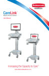
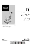
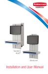
M38 Carts
User Manual
For Models with Manual Lift
Increasing the Capacity to Care™
www.rubbermaidhealthcare.com
Warnings
IMPORTANT – Indicates a situation that does not present any hazard but is
very important in maintaining a well functioning workstation.
ATTENTION – Consult manual to avoid a potentially
hazardous situation which may result in minor or moderate injury.
ELECTRICAL – Indicates an impending electrical hazard
which, if not avoided, may result in personal injury, fire and/or death.
• The supplied power cord is rated for medical use. Connecting the cord to an outlet that
is not medical grade (indicated with a green dot) will not ensure grounding protection.
• Where the integrity of the external PROTECTIVE EARTH GROUND CONDUCTOR
arrangement is in doubt, the equipment shall be operated from its internal electrical
power source (battery).
• Power cord, USB extension, and workstation are for INDOOR use only. DO NOT
OPERATE OUTDOORS.
• Keep power cord away from water. DO NOT PLUG CORD INTO OUTLET IF WET.
• DO NOT OPERATE PRODUCT IF WET. If the WORKSTATION becomes wet, unplug it
immediately, wipe off any excess liquid, and allow it to dry before using again.
• Inspect power cord before integration. DO NOT USE POWER CORD IF DAMAGED.
• Fully insert power cord plug into outlet. DO NOT unplug by pulling on cord. DO NOT
remove, bend or modify any metal prongs or pins of power cord.
• DO NOT use excessive force to make mechanical or electrical connections.
• DO NOT obstruct the cooling vents.
• DO NOT use an electrical extension cord with your workstation.
• DO NOT use a flammable cleaner on the station as it can result in fire or explosion.
• DO NOT overload the cart. Weight of technology components and monitor not to
exceed 30 pounds (13.6 kg). Weight of monitor not to exceed 15 lbs. (6.8 kg).
• DO NOT operate the cart on an incline exceeding 10 degrees.
• DO NOT use the cart to power equipment that is not part of the configured cart
system.
• DO NOT connect equipment that is not mounted on the cart into the power system
outlets. The power system is designed for power cart mounted equipment only.
• Equipment not suitable for use in the presence of a FLAMMABLE ANESTHETIC
FIXTURE WITH AIR, or WITH METERED OXYGEN OR NITROUS OXIDE.
Do not adjust lift mechanism until cart has been outfitted with technology.
Failure to do so may cause the shuttle and work surface to rise rapidly when
actuator is released potentially causing personal injury or damage to the cart.
To avoid potential electrical shock, DO NOT simultaneously touch any cart
system components and the patient or any apparatus not connected to the cart
system. Electric current may try to flow through you between the M38 system and the
other point of contact as it seeks the easiest path to ground.
3
Table of Contents
Warnings
3
Introduction
6
Box Contents ...................................................................6
Specifications ...................................................................7
Statement of Use..............................................................7
Introduction
8
Overall View......................................................................8
Get Started
9
Install the Power Cord .....................................................9
Charge the Battery
(Carts w/Power, RX/XP Medpak Expansions)....................9
Setup
11
Setup Procedure ..............................................................11
Remove the Work Surface ................................................12
Install Keyboard and Mouse .............................................13
Install the Monitor .............................................................14
Install the Monitor .............................................................15
Install a Thin Client or closed Laptop ................................15
Install a Laptop Computer ................................................16
Install the Work Surface ....................................................17
Adjust the manual Work Surface Lift Preload ....................18
Configure the control system (RX/XP MedPak Expansion) 19
Operation
20
Quick Start Procedure ......................................................20
The Manual Work Surface Lift ...........................................20
The Keyboard tray ............................................................21
The Keyboard Light ..........................................................21
Single Locking Drawer ......................................................22
The Casters ......................................................................24
Power On/Power Off the M38 cart....................................24
AC Power Expansion Rubbermaid User Interface (RUI) ....25
Power on/Power off AC Powered Carts ............................25
DC Power Expansion User Interface (RUI).........................26
4
Power On/Power Off dc powered Carts............................26
Battery Cutoff Switch
(Non-Powered w/Drawer Expansion) ................................27
lcd Rubbermaid User Interface (RUI) .................................28
Power on/Power off Non-Powered Carts ..........................28
The Mute Button ..............................................................29
Adjust the Contrast of the LCD .........................................29
Battery Charge Indicators (Powered Carts) .......................30
Battery Charge Indicator (continued) .................................31
Unlock and Lock the Drawer Modules ..............................32
The Drawer Modules (continued) ......................................33
Maintenance
34
Remove and Replace the Battery .....................................34
Remove and Replace the Input Power Fuses ...................35
Remove and Replace the Battery Power Fuse ..................35
Change the Drawer Lock Combination .............................36
Troubleshooting
40
Cleaning
42
Service
43
Service Request ...............................................................43
Service Level Commitment ...............................................43
Warranty
43
Limited Warranty for M38 Computer Cart .........................43
Service Details ..................................................................43
Transport/Storage/Disposal
44
Transport/Storage.............................................................44
Cart/Battery Disposal .......................................................44
Standards Compliance
45
5
Introduction
BOX CONTENTS
A
x2
A
M38 Cart
B
Security Keys
C
Power Cord
D
M38 User Manual
E
Accessory Kit
B
C
E
E2
D
M38 Carts
User Manual
E3
For Models with Manual Lift
E1
E4
E1
Power Cord Clip
E2
Mouse/Keyboard Cord Clips
E3
Security Bit Kit
E4
Drawer Module Lock Overide Key †
™
Increasing the Capacity to Care
www.rubbermaidhealthcare.com
†
Carts Equipped with Drawer
Modules Only
Introduction
SPECIFICATIONS
Base Size
17” x 19” (43.2 cm x 48.3 cm)
Weight
Configurations starting at 100 lb (45.4 kg)
Height Adjustment
Up to 16” (40.6 cm)
Cart Height
49.3" to 65" (125.2 cm to 165.3 cm)
Keyboard Height
4.8" (12.2 cm) of vertical travel.
Work Surface
18” w x 15” d (52.7 cm w x 25.4 cm)
Casters
4" (10.2 cm) 2 Locking
Keyboard Platform
Accommodates 1.75” H x 18" W x 8” D (4.5 cm x 45.7
cm x 20.3 cm) USB keyboard
21.5" x 11.1“ x 2.9" (54.6 cm x 28.3 cm x 7.5 cm)
CPU Cavity
LCD Monitor Mount
15 lbs (6.8 kg) max. 24" Monitor Max.
Power Cord
2.5 ft (.75 m ) hospital grade spiral cord– extends to 8 ft
(2.4 m), recharges on board technology, 120/240 VAC,
6.3 A, 50/60 Hz.
Power Strip
• NEMA X3 Mutiple Socket Outlet
UPS input
120 Vac, 5.1A (fused) North America
UPS output
230 Vac, 2.5 A (fused) International Models
12 Vdc @ 12.5A or 120 Vac @1.25A
Sealed Lead Acid (SLA)
Battery
Lithium Battery
35 or 55 Ahr/12 V AGM (fused Battery Output)
12 Ahr (non-powered cart)
U1-12Vdc @ 512Wh (fused Battery Output)
STATEMENT OF USE
The M38 Mobile Computer Cart is designed and manufactured by Rubbermaid
Healthcare. Rubbermaid Healthcare is dedicated to providing innovative quality products.
Our goal is to increase the capacity to care by improving productivity, ergonomics, and
compliance while enhancing your facility image.
•
The M38 Mobile Computer Cart is a mobile computing workstation cart designed for
safe use in general patient areas for the purpose of clinical data entry and retrieval,
and medication delivery.
•
The M38 Mobile Computer cart is not intended for home use.
•
The M38 Mobile Computer cart operates from both AC and DC (rechargeable
battery) power sources.
•
The M38 Mobile Computer cart has no potential electromagnetic or other interference
risks when operated according to guidelines covered in this instruction manual.
7
Introduction
OVERALL VIEW
Monitor
( customer provided )
AC Power User Interface
( some models )
LCD Cart
Configuration
Keyboard Tray
Power System
Compartment
( some models )
Monitor
Mount
Rear
Handle
Manual Height
Handle
Storage Bin
Manual Drawer
Lock Overide
Power
Cord
Screen
Clamp
Document
Cover
Non-Locking
Caster
Locking Power
Caster
Inlet
Mouse Pad
Mouse Holder
Rubbermaid User Intereface
( Drawer models )
Drawer Module
( some models )
8
Laptop Cart
Configuration
Get Started
INSTALL THE POWER CORD
Install the power cord.
1. Plug the power cord into
the power inlet as shown.
1
2. Place the plug in the cord
holder.
2
CHARGE THE BATTERY (CARTS W/POWER, RX/XP MEDPAK EXPANSIONS)
1
When carts configured with
battery powered expansions
are new, or have been removed
from service for more than
30 days, the battery must be
conditioned.
To condition the battery:
1. Plug in the power cord.
2. Leave the cart plugged in
for approximately 8 hours.
2
Note: The initial RUI
(Rubbermaid User Interface)
charge indicator reading may
be incorrect. Charge the cart for
8 hours to ensure that battery is
at full charge, and that charge
indicator is set to the correct
level of charge.
9
Setup
THIS PAGE HAS BEEN PURPOSELY LEFT BLANK
10
Setup
SETUP PROCEDURE
1. De-energize the M38 cart.
2. Remove the storage bins.
3. Remove the work surface.
4. Install the keyboard and mouse.
5. Install any technology devices.
• Monitor, CPU or laptop, USB hub . . .
6. Test and Troubleshoot the installation
• Make sure all connections are correct
• Power the M38 cart
• Start the technology devices and troubleshoot as necessary
• Configure the technology devices to power on when the cart is powered on
7. Configure the control system on models equipped with electronic controls.
8. Replace the work surface and storage bins.
9. Adjust lift mechanism preload on carts equipped with the manual surface lift.
The M38 cart is ready for use.
To fully shut down (de-energize) a DC powered cart for service or
cleaning you must:
1. Unplug the power cord.
2. Press and hold down the Power button to power down the
cart and internally disconnect the battery from the electrical
system.
If the power cord is plugged in after the POWER button is pressed,
the battery will reconnect and the cart will power up automatically.
To power up the cart after shut down, you must plug in the power
cord to reconnect the battery to the cart electrical system.
To fully shut down a non-powered cart:
1. Unplug the power cord.
2. Position the battery cut-off switch to the OFF position.
Observe local safety procedure (e.g., lock out/tag out) to ensure
that cart remains
de-energized during maintenance and cleaning cycles.
11
Setup
REMOVE THE WORK SURFACE
2. Turn counter clockwise to
unlock the work surface.
1
1
1. Insert the security key in the
lock as shown.
2
1. Pull the latch to unlock the
work surface.
2
2
2
1
12
2. Grasp a front handle, and
grasp the opposite side of
the of the work surface.
3. Lift the front of the work
surface, then pull the work
surface toward you.
Setup
INSTALL KEYBOARD AND MOUSE
1. Grasp the front edge of the
keyboard tray and pull it
toward you to extend the
keyboard tray.
1
1
2. Place the keyboard and
mouse on the keyboard
tray. Use self adhesive hook
and loop material to keep
the keyboard in position.
2
2
Route the keyboard and mouse
cables through the rear or side
ports of the technology tray as
shown.
13
Setup
INSTALL THE MONITOR
1
2
1. Turn the locking screw
counter clockwise to loosen
the locking screw as shown.
2
2. Remove the monitor mount.
1
Use the mounting screws
provided with the monitor to
attach the monitor mount to the
monitor.
Note: The mounting holes
may need to be enlarged to
accommodate the monitor
mounting screws.
Note: If mounting screws
are not provided, refer to the
monitor documentation for
the correct mounting screw
size.
Note: It may be easier to
connect the monitor cables
while the monitor is off the
M38.
14
Setup
INSTALL THE MONITOR
3
1. Insert the monitor/mount
assembly onto the column
mount.
2. Install the monitor cables.
3. Route the video and power
cables to the technology
tray; then plug the power
cord into the power strip.
INSTALL A THIN CLIENT OR CLOSED LAPTOP
1. Place the laptop/thin client and
power supply in the technology
tray.
2. Connect the cables.
3. Plug the power cord into the
power strip.
Note: to power the task light on an
unpowered cart, plug in the black
USB cable onto a powered USB
port or hub.
Note: To monitor the power supply,
connect the beige USB cable to
the computer.
Note: A small form-factor
computer may be mounted to the
rear column. Contact Rubbermaid
Healthcare at customer.service@
rubbermaidhealthcare.com
or 888-859-8294 for more
information.
15
Setup
INSTALL A LAPTOP COMPUTER
1
1. Place the laptop on the wire-form
platform.
• Connect the cables to the laptop.
• Plug the power supply into the
power strip.
2
1
Note: Use self-adhesive hook and loop
material to anchor the laptop to the
platform
Note: to operate the task light on a
non-powered cart, plug in the black
USB cable onto a powered USB port
or hub.
2. Open the laptop and rest the lid
against the column.
2
Use the thumb screws to raise the rear
of the laptop platform so the bottom of
the screen will be visible when the work
surface is installed.
3
2
1
1. Loosen the monitor clamp screw.
2. Lower the monitor clamp until it
contacts the top of the monitor as
shown.
3. Tighten the monitor clamp screw.
3
16
Setup
INSTALL THE WORK SURFACE
1
1
1. Align the work surface rear
latches with the latch pins
on the technology tray as
shown.
2. Lower the front of the work
surface and engage the
latches at the front of the
technology tray.
2
2
2
1. Push in the latch.
Try to lift the work surface
to make sure the latch is
locked.
1
2. Turn the security key
clockwise to lock the work
surface.
2
3. Remove the security key.
3
17
Setup
ADJUST THE MANUAL WORK SURFACE LIFT PRELOAD
On models equipped with the manual
work surface lift, it may be necessary
to adjust the lift preload to compensate
for the weight of the technology
components added during setup.
Adjust the lift preload as follows:
1
1. Use a soft tool to pry and remove
the column top cap (1).
2. Use a 17mm (11/16) wrench to turn
the adjusting
screw (2) as necessary.
• Turn the screw clockwise to
increase the preload.
•
2
Turn the screw counter clockwise
to decrease the preload.
3. Raise and lower the work surface to
test the adjustment
4. Repeat steps 2 — 3 until the lift is
adjusted
Note: The lift is adjusted when the
work surface can be raised and
lowered with approximately the same
effort.
5. Replace the top cap (1).
18
Setup
CONFIGURE THE CONTROL SYSTEM (RX/XP MEDPAK EXPANSION)
The electronic drawer control system offers a number of configurable advanced features
which aid cart and fleet management.
Cart interface configuration software application and drivers are available for download
at – www.rubbermaidhealthcare.com/welcome
Control system features available for configuration are listed below:
Keyless Entry System PIN Number Management– The drawer control system stores
up to 128 PIN numbers. PIN numbers control the locking mechanism for the RX and XP
and side mounted drawer modules.
Keyless Entry System Auditing– The drawer control system keeps a rolling log of PIN
transactions listed by PIN number. Log data can be exported for off-line review.
Asset ID/Tagging– The Cart Name and Serial are provided for asset management.
Serial is entered into the controller at manufacture and may only be viewed with the
configuration software. Cart Name is displayed on the LCD, and is configurable with the
with the software application.
Timers– The configuration software sets timers for the following:
• Drawer Lock-Down Time 1 - 255 seconds
• Keyboard Light Time-out 1 - 255 seconds
• LCD Backlight Time-out 1 - 99 seconds
Power Alert/Power Management Applications
The optional battery/power supply monitoring software application may be installed on
the (customer supplied) installed computer. This software monitors battery usage and
provides an indication of the current physical condition of the battery. The monitoringt
software also logs data log to either the installed computer or user's network depending
on the configuration. The Power Alert/Power Management Applications are available for
download at– www.rubbermaidhealthcare.com/welcome
19
Operation
QUICK START PROCEDURE
Good practice for starting the M38 cart is as follows:
1. Turn on the cart (see "Power On the M38 Cart" p24-28)
2. Note the condition of the battery (the cart may need to be
plugged in p30-31)
3. Move the cart to the desired location.
• Unplug the cart from the wall outlet.
• Place the plug in the cord holder.
• Unlock the casters. (p-24)
• Move the cart.
4. Lock the casters.
5. Adjust the work surface height. (see "Manual Work Surface
Lift" p-21).
6. Enter Your PIN to unlock the drawers (see p32-33).
7. Set work light as needed. (see "Keyboard Light" p21)
8. When you finish your work cycle return the cart and plug it in to
charge.
Note: Plug the cart into an electrical outlet when it will be left
unattended for any length of time.
THE MANUAL WORK SURFACE LIFT
To raise or lower the work surface:
1a. Position your hands to hold the
work surface steady,
1
2. Raise or lower the work surface
to the desired height.
2
3. Release the height lever; then,
slightly raise or lower the work
surface to make sure the
locking pin is seated. (You will
feel the locking pin detent and
lock in position if is not seated.)
3
20
1b. Lift the height lever that is
located beneath the right
handle.
Operation
THE KEYBOARD TRAY
To extend the keyboard tray, pull
the key board tray toward you
until it stops.
To retract the keyboard tray, push
in on the keyboard tray until it
stops.
To extend the mouse pads, grasp
the edge of the mouse pad and
twist it to the open position.
To push the front edge of the
mouse pad to twist it to the
closed position.
THE KEYBOARD LIGHT
A keyboard light is included to
enhance cart usability in darkened
patient areas. The keyboard light that
is operated by using the Light button
located on the membrane keypad at
the front of the cart.
The keyboard light is designed
to illuminate the keyboard in the
extended position. When the keyboard
tray is retracted, the keyboard light will
illuminate the floor in front of the cart.
To use the keyboard light:
•
Press the Light button
on the keyboard light.
•
Press the Light button again to
turn off the keyboard light.
to turn
Note: The keyboard light will turn off
automatically when the when the
keyboard light timer counts down
to zero.
21
Operation
SINGLE LOCKING DRAWER
1
Unlock the Drawer
Enter the combination.
1
3
2
4
5
Note: The factory preset
combination is as follows:
1. Press and release buttons 2
and 4 simultaneously.
2. Then press and release
button 3.
2
Turn the control knob to the
right (clock wise).
4
3
22
5
Open the drawer.
If the drawer will not open,
repeat steps 1-3.
Operation
SINGLE LOCKING DRAWER
1
Lock the Drawer
With the drawer unlocked,
Close the drawer.
2
Turn the control knob to the
left (counter clockwise) until it
stops, then release.
4
3
5
Try to open the drawer.
If the drawer is not locked
repeat steps 1-3.
23
Operation
THE CASTERS
To operate the casters:
• Lower the tab with your toe
to lock a caster.
• Lift the tab with your toe to
unlock a caster.
POWER ON/POWER OFF THE M38 CART
Note: The M38 cart should only be powered off for the following conditions:
• The audible alarm cannot be muted.
•
When the cart will not be used for an extended period (the cart is placed in
storage.)
• For maintenance.
• If the cart is moved to a different facility.
To fully shut down a DC powered cart for service or cleaning you must:
1. Unplug the power cord.
2. Press the power button to power down the cart and internally
disconnect the battery.
If the power cord is plugged in after the shutdown button is pressed, the
battery will reconnect and the cart will power up automatically.
To power up the cart after shutdown, you must plug in the power cord to
reconnect the battery to the cart electrical system.
24
Operation
AC POWER EXPANSION RUBBERMAID USER INTERFACE (RUI)
The LED RUI is included on M38
computer carts configured with the
AC Power Expansion but without
drawer expansions. The LED RUI
controls the AC power supply and
monitors the condition of the cart
power battery.
1
Power Indicator The left hand LED
is the power indicator. If the light
is green, there is AC power to the
installed technology devices.
Battery Charge Indicator The other
four LEDs are the battery charge.
Each LED indicates roughly 25%
charge. The battery indicator is
further explained on pages 30-31 of
this manual.
POWER ON/POWER OFF AC POWERED CARTS
To Power On AC powered carts:
1. Plug in the power cord.
2. Press and hold the power button
for 3-5 sec.
Note: The RUI displays the battery condition and
the keypad will function.
Note: Plug the cart into an electrical outlet when it
will be left unattended for any length of time.
To Power Off AC powered carts:
1. Unplug in the power cord, and place it in the cord
holder.
2. Press and hold the power button
for 3-5 sec.
The RUI goes dark or blank and the keypad will not
function. Cart power to all devices plugged into the
cart power system is turned off.
The cart is electrically de-energized for cleaning or
maintenance
25
Operation
DC POWER EXPANSION USER INTERFACE (RUI)
The DC RUI is included on M38
computer carts configured with the DC
Power Expansion but without drawer
expansions. The DC RUI controls the
dc power supply and monitors the
condition of the cart power battery.
Auto Shutdown – indicates the battery level
is too low to operate the cart and a safe
shutdown of the cart has started.
Low battery – The battery charge must be
topped up. LED will illuminate at 20 min.
run-time or less.
Charging – A flashing Charging LED
indicates the battery is accepting a charge
from ac power.
Recovery – Indicates the dc power system
is in a recovery cycle, and should be left to
charge for 6-8 hours.
AC/DC – AC indicates the cart is plugged
into a wall outlet. DC indicates the cart us
unplugged and operating on battery power.
Battery Indicator is explained on pgXX of
this manual.
POWER ON/POWER OFF DC POWERED CARTS
To Power On dc powered carts:
1. Plug in the power cord.
2. Wait 3-5 sec the power supply will turn on
automatically.
The RUI will display the battery condition and the
keypad will function.
Note: Plug the cart into an electrical outlet when it will
be left unattended for any length of time.
To Power Off the dc powered carts:
1. Unplug in the power cord.
2. Press and hold the power button
for 3-5 sec.
The RUI goes dark or blank, the keypad will not
function, and power to all devices plugged into the cart
power system is turned off.
The cart is electrically de-energized for cleaning or
maintenance as long as the power cord is
not plugged in.
26
Operation
BATTERY CUTOFF SWITCH (NON-POWERED W/DRAWER EXPANSION)
Non-powered carts configured
with electronic expansions are
fitted with the battery powered
non-powered control system.
The control system design
includes a battery cutout switch
to de-energize the control
system for maintenance,
storage, and shipping. New
M38 carts are shipped in the
de-energized state, with the
cutout switch off. The cutout
switch must be switched on as
shown in order to power-on the
cart. There are two methods to
access the cutout switch.
Front Cover Cut Away For Clarity
• The easiest method is to
reach under the cart and
switch on cutoff switch
through the opening at
the bottom of the cart as
shown.
For those who are unsure of
where the switch is located:
1. Remove the 2 front cover
screws (1) from base of the
cart.
2. Lift and remove the front
cover from the base as
shown.
2
1
1
3 Switch on the cutoff switch
from above. The cutoff
switch is located as shown
above.
4. Replace the front cover (2)
and screws (1).
The cart is ready to power on.
27
Operation
LCD RUBBERMAID USER INTERFACE (RUI)
M38 powered and non-powered
carts configured with the electronic
locking RX or XP drawer expansion
are equipped with the Rubbermaid
User Interface (RUI). The RUI
controls the low battery alarm,
keyboard light, drawer control
system, power supply, and PIN
entry to unlock the drawers.
Depending on the cart power
configuration, use one of 3
methods to power on/power off
the Cart:
• For AC powered carts see
page 25.
• For DC powered carts see
page 26.
• For Non-Powered carts see
page 28.
POWER ON/POWER OFF NON-POWERED CARTS
To power on non-powered carts:
Note: The Power button
is not used by the
non-powered control system. The battery cutoff
switch is the power switch.
1. Turn on the Battery cutoff switch as shown.
2. Plug in the power cord.
The RUI will display the battery condition and the
keypad will function.
Front Cover Cut Away For Clarity
Note: Plug the cart into an electrical outlet when
it will be left unattended for any length of time.
To power off non-powered carts:
1. Unplug in the power cord.
2. Turn off the battery cutoff switch as shown.
The RUI goes dark or blank and the keypad will not
function. Cart power to all devices plugged into the
cart power system is turned off.
Front Cover Cut Away For Clarity
28
The cart is electrically de-energized cleaning or
maintenance.
Operation
THE MUTE BUTTON
The Mute Button
is used to
silence the power system audible
alarm.
To mute the audible alarm, press
and hold down the mute button
until the alarm is silenced.
Note: When the battery is at 10%
(1/8) charge or less, the audible
alarm will sound after again a
minute when the mute button is
used until the power system is
turned off or the cart is plugged
in to charge the battery. Failure
to plug-in or turn off the power
system will damage the battery.
Note: Do not allow the battery
charge to drop below 20% (1/4),
the battery may lose the ability to
recharge.
ADJUST THE CONTRAST OF THE LCD
The LCD level of contrast is
adjusted as follows:
To increase the contrast:
1. Press and hold down the
SETUP key.
2. Repeatedly press the 2 key
(the up arrow) until the display
shows the desired level of
contrast.
To decrease the contrast:
1. Press and hold down the
SETUP key.
2. Repeatedly press the 8 key
(the down arrow) until the
display shows the desired
level of contrast.
29
Operation
BATTERY CHARGE INDICATORS (POWERED CARTS)
M38 cart power expansions are equipped with a battery gauge that displays the level
of battery charge. Powered carts without powered drawer expansions are equipped
with LED battery gauges. The RUI for powered carts equipped with powered drawer
expansions has an LCD battery gauge.
The RUI also indicates power system status:
• Normal
greater than 50%
to 100%,
• Charge Mode
• Recovery
The cart may be unplugged and used on
battery power.
less than 50%
to 20%
The cart should be plugged in to charge, but
may be used on battery power alone. The
audible alarm will sound but may be muted.
less than 20%
The cart must be plugged in. The cart may
shutdown for deep discharge recovery cycle
and should remain plugged in for 6-8 hours.
Powered components will not be available
during this period. The audible alarm will
continue to sound. When battery level drops
below 10% the alarm cannot be muted unless
the cart is plugged in.
Caution: Never allow battery charge level to drop bellow 20% (1/4), Failure to keep
the battery charge greater than 20% may damage the battery and render it unable
to recharge.
AC Power LED User Interface
The condition of the LEDs and audible alarm
for corresponding levels of battery charge
are listed in the table below
Charging Indicator Summary (Discharging)
Indicates Power
On/Off Only
O
O
O
O
O
Approximate
Battery Charge
Level
30
Low Battery
Alarm
90-100%
Green
Green
Green
Green
Off
50-89%
Green
Green
Green
Off
Off
20-49%
Yellow
Yellow
Off
Off
On
<20%
Flashing Red
Off
Off
Off
On
Operation
BATTERY CHARGE INDICATOR (CONTINUED)
DC Power LED User Interface
The DC power LED RUI battery gauge uses 17 LEDs arrayed in a straight line pattern
along the gauge area of the RUI. Charge level is indicated on the scale one illuminated
LED at a time.
The Recovery LED will flash when the power supply shifts to recovery mode.
The Charge LED will flash when the power supply is plugged in and charging the battery.
0
100%
Battery Charge
Level
Low Battery
Alarm
Cart Condition
7/8 - F
Normal
Off
1/2 - 13/16
Normal
Off
1/8 - 7/16
Charge Mode
On
less than 1/8
Recovery
On
Powered Drawer Expansion LCD User Interface
The LCD displays a graphic battery gauge. The interior of the battery graphic displays 6
bars to indicate charge level.
Charging - The indicator bars scroll to indicate charging.
Recovery - The xxxxxxxxxxxxxxxxxxxxxxxxxxx
Approximate
Battery Charge
Level
Low Battery
Alarm
1
2
3
4
5
6
>83%-100%
On
On
On
On
On
On
Off
>65%-83%
On
On
On
On
On
Off
Off
>49%-65%
On
On
On
On
Off
Off
Off
>33%-49%
On
On
On
Off
Off
Off
On
>16%-33%
On
On
Off
Off
Off
Off
On
>0%-16%
On
Off
Off
Off
Off
Off
On
31
Operation
UNLOCK AND LOCK THE DRAWER MODULES
Drawer Locks
The drawers are accessible when a valid personal identification number (PIN) is entered
into the controller. A user may lock the drawers by either pressing the Lock
button or by waiting until the drawer lock timer counts down. The electronic drawer lock
will not function when the battery is dead, conditioning, or if the cart is electrically deenergized. When there is no power to the drawer module, open the drawers by using the
manual lock override that is located at the rear of the drawer module.
Press the number keys (1-0) to enter the 4 digit
PIN code.
Note: The factory default PIN is 8034.
*
As you enter digits a symbol is displayed to
indicate that a digit has been entered into the
controller.
If the 4 digits entered are a valid PIN, the drawer
module will unlock and the Drawers Unlocked
message will be displayed.
If the digits are not a valid PIN, the Error Invalid
Code message is displayed for a short time;
then the displays changes to the battery monitor.
32
Operation
THE DRAWER MODULES (CONTINUED)
Manual Drawer Lock
Use the manual drawer lock
override as follows:
1. Insert the lock override key
into the lock located on the
rear of the drawer module.
The Drawers are locked, the
key may be removed from
the lock.
2. Turn the key clockwise to
open the drawers.
The key cannot be removed
while the drawers are
unlocked.
Drawers
Locked
Drawers
Unlocked
3. Turn the key counter
clockwise to lock the
drawers and remove the key.
Drawer Labeling
Drawers are equipped with a dual labeling system that is located on the drawer pull.
There are Wet-erase labels located beneath the clear label guard (white for locking
drawers, gray for non-locking). Also, the label guard forms a pocket which accepts a 4
1/8 ¨ (10.5 cm) X 7/8 ¨ ( 2.2 cm) paper or card label.
Label the drawers in the following manner:
1. Wet-erase labels:
a. Remove the clear plastic label guard.
Ex
Vis
po
1
a
Vis
b. Use a wet-erase marker (Expo Vis-A-Vis
or equivalent) to label the drawer.
c. Replace the label guard.
2
2. Paper labels
a. Cut out and print a sufficient number of
4 1/8¨ X 7/8" labels.
b. Insert the label between the label guard
and the dry-erase surface.
33
Maintenance
REMOVE AND REPLACE THE BATTERY
Power down the M38 cart and
remove the rear cover:
1
1
1. Unplug the M38 cart from the
wall outlet.
2
2. Press and hold down
the power button
(approximately 2 seconds)
to turn off the M38 cart.
2. Remove the power cord (1)
from the rear of the M38
cart.
3
3. Use a 4mm hex key wrench
to remove 2 screws (4) and
Battery Cover (3) from the
rear of the M38 cart.
4
Reverse the steps of this
procedure to replace the rear
cover and power cord.
4
Remove the battery:
2
1. Unbuckle the web belt (7).
2
1
2. Remove bolt (1), lock washer
(2), washer (3), and Red
cable (5) from positive battery
terminal (4).
3
3. Remove bolt (1), lock washer
(2), washer (3), and Black
cable (8) from negative battery
terminal (9).
6
4. Remove battery (6) from the
M38 cart.
8
9
7
34
5
4
Reverse steps of this procedure
to install the battery.
Maintenance
REMOVE AND REPLACE THE INPUT POWER FUSES
1
1
2
2
1
Power down the M38 cart,
remove the rear cover, remove
the battery, remove and replace
the fuses.
1. Power down the M38 cart
and remove the rear cover
as directed on page 34 of
this manual.
1
2. Remove the battery as
directed on page 34 of this
manual.
3. Twist open fuse holders
(1) and remove fuses (2).
Discard blown fuses.
Replace fuses with Cooper
Busman AGC-6 or
equivalent.
Base Cut Away For Clarity
Reverse the order of the steps
of this procedure to reassemble
the cart.
REMOVE AND REPLACE THE BATTERY POWER FUSE
1
2
1
Power down the M38 cart,
remove the rear cover, remove
and replace the battery fuse.
1. Power down the M38 cart
and remove the rear cover
as directed on page 34 of
this manual.
2. Remove the lower half of
battery fuse holder (1) as
shown.
3. Remove fuse (2). Discard the
blown fuse.
Replace fuse with Littlefuse
ATOF 0287030 30A or
equivalent.
Base Cut Away For Clarity
Reverse the order of the steps
of this procedure to reassemble
the cart.
35
Maintenance
CHANGE THE DRAWER LOCK COMBINATION
1a
Never close the drawer to
test a new combination. If the
combination fails, you will need
a service call to get the drawer
open.
Use the current combination to
open the drawer.
Note: The factory preset
combination is as follows:
1b
1. Press and release buttons 2
and 4 simultaneously.
2
1
2
3
2. Then press and release
button 3.
5
1. Remove the 2 screws (1)
from the cover (2).
1
2
2
36
4
2. Slide the cover (2) back,
then lift it away from the
drawer assembly to expose
the drawer lock.
Maintenance
CHANGE THE DRAWER LOCK COMBINATION (CONTINUED)
3
Turn the control knob to the
left (counter clockwise) to the
stop position, then release. This
clears previously used buttons.
5
4
4
Enter the existing combination.
1
5
2
3
4
5
Press on the combination
change lever (located at the rear
of the lock) until you hear and
feel a detent.
37
Maintenance
CHANGE THE DRAWER LOCK COMBINATION (CONTINUED)
6
Turn the control knob to the
left (counter clockwise) to the
stop position, then release. This
clears previously used buttons.
5
4
Enter the new combination.
7
Note: Any of the buttons may be
used in the new combination,
either pressed simultaneously or
individually.
1
3
2
4
5
Each button may only be used
once.
A one button combination is not
recommended.
Write down your new
combination.
8
Turn the control knob to the
right (clockwise) to the stop
position, then release. This
activates the new combination.
4
5
Enter the new combination and
test the operation of the lock
(with the drawer open).
Note: The lock can be disabled
by following the combination
change procedure and omitting
step 7.
To reactivate the lock follow the
combination change procedure
and omit step 3
38
Maintenance
CHANGE THE DRAWER LOCK COMBINATION (CONTINUED)
9
1. Slide the lock cover into
position.
2
2. Install the 2 screws on the
cover.
3. Close and lock the drawer.
1
2
1
39
Troubleshooting
Cart Will Not Power Up:
• Plug power cord into a working hospital grade outlet
• Check to ensure power cord is plugged securely into back of cart
• Check to see if the Power System Interfaces (PSI) is charging when plugged in.
• If the charge level is critically low (last one or two LED’s on) let cart charge until full
• If the cart does not start, check that cables to the PSI are securely plugged in.
Cart Will Not Charge:
• Check to ensure external spiral cord is plugged into base of cart.
• Ensure outlet is functionally operational
• Plug the power cord into a working hospital grade outlet.
• Check to make sure the power cord is plugged securely into the back of the cart.
• Check to see if the PSI indicates the station is charging when plugged in.
• If the charge level is critically low (last one or two LED’s on) let the cart charge until
full
• If the cart still does not charge, check to see if cables to the PSI are securely plugged
in.
Audible Alarm Will Not Turn Off:
• When the battery reaches approximately 10% of capacity remaining, the audible
alarm will sound. The alarm may be muted for 1 minute. Until the cart is plugged in to
charge the audible alarm will continue to sound every minute.
• If alarm fails to go off after plugging in cart for several minutes, power down unit by
holding on/off button for 2 seconds.
Cart Is Hard To Push:
• Check that the caster locks are in the unlocked (up) position
• Examine casters to see if any debris is caught in them
40
Troubleshooting
Keyboard Tray will Not Raise or Lower:
• Check for cable obstructions.
• Adjust the keyboard arm tray arm knob counter-clockwise to loose
• Adjust the keyboard arm tray arm knob clockwise to tighten
Keyboard Light Does Not Work for Non-Powered Version:
• Make sure USB cable is plugged into Laptop
Keyboard Light Does Not Work for Powered Carts:
• Verify powered USB Hub is plugged into power supply (green light indicator)
• Check to ensure USB cable is plugged into Hub
Mouse Does Not Work Properly (Powered Cart Only):
• Verify powered USB Hub is plugged into power supply (green light indicator)
• Make sure mouse is plugged into the USB hub
• If problem persists, plug device into another cart to see if it functions properly
Keyboard Does Not Work Properly:
• Ensure USB Hub is powered and plugged into power supply (green light indicator)
• Make sure keyboard is plugged into the USB hub
• If problem persists, plug device into another cart to see if it functions properly
Computer Does Not Work Properly:
• Check that computer has power
• Check the battery charge. If less than 20%, recharge the battery
• If problem persists, plug device into another cart to see if it functions properly
41
Cleaning
CAUTION: Because of the close proximity of electrical power and
equipment, flammable cleaners should never be used on the cart!
• Verify that your cart is powered down and unplugged from the wall outlet before
cleaning.
• Allow your cart to dry completely before plugging the power cord into a wall outlet.
• When cleaning the cart, wipe cleaners off of surface with a damp cloth and thoroughly
dry.
• Never cover the cart or its components in liquid or allow liquids to flow into the cart.
• Never use steel wool or other abrasive material as these could damage the surface
finish
• Before using any cleaner on the cart, first test on a small area to ensure that the
surface is not harmed. These guidelines cannot guarantee infection control. The
hospital’s Infection Control administrator should be consulted for cleaning procedures
and processes.
RECOMMENDATIONS:
• Clean plastic components with diluted, non-abrasive solutions. Suggested cleaners
are water, soap, diluted bleach and alcohol solutions.
• Remove pen and dry erase marker stains with a soft cloth and 91% isopropyl alcohol.
• Remove iodine stains with a soft cloth and any cleaners suggested above.
DO NOT use the following chemicals to clean your cart: Acetone, Mineral Spirits,
Abrasive Cleansers, Paint Thinner or any other harsh or toxic chemicals.
CLEANING OF HIGH TOUCH POINT ITEMS
1. Work Surface is fully removable to facilitate cleaning (see Step 1 of Start up
instructions)
2. Document Protector is removable for cleaning by pulling up on back corners. To
replace press nylon fastener into hole in work surface. Document protector is a
replaceable item
3. Back Handle is fully removable (see Step 9 of Start up instructions)
4. Rear Bins can be removed by grabbing outside edge of bin and lifting up
5. Keyboard Tray and Mouse Pads - Tray and mouse pads are composed of melamine
resin and are easy to wipe down.
42
Service
SERVICE REQUEST
Contact your IT department, or file a service request at our website:
www.rubbermaidhealthcare.com/service
SERVICE LEVEL COMMITMENT
Rubbermaid Healthcare is committed to providing best-in-class service. This document
details our standard warranty and instructions to request service using our customer
support system.
• Rubbermaid Healthcare will provide a service manual upon request.
Warranty
LIMITED WARRANTY FOR M38 COMPUTER CART
Rubbermaid Healthcare is pleased to offer a three-year warranty on durable components
and a three-year warranty on electronic components.
If during the warranty period this Rubbermaid Healthcare product proves defective in
materials or workmanship under normal use by the original purchaser, please contact
Rubbermaid Healthcare technical support (please be ready to furnish complete
information, including product serial number, description of the issue, and full contact
information). Rubbermaid Healthcare will determine, at its sole discretion, how to
best address your warranty issue, which may include sending you a replacement part
covered under warranty or for sale. Rubbermaid Healthcare reserves the right to require
proof-of-purchase prior to honoring any warranty request. This warranty does not cover
product abuse, modification, failure to adhere to product instructions, or improper
operation/misuse. RUBBERMAID HEALTHCARE SHALL NOT BE LIABLE FOR ANY
CONSEQUENTIAL OR INCIDENTAL DAMAGES WHATSOEVER. Some states do not
allow the exclusion or limitation of incidental or consequential damages, so the above
limitation or exclusion may not apply to you. This warranty gives you specific legal rights
and you may also have other rights which vary from state to state or country to country.
SERVICE DETAILS
Consumable components are not covered under warranty and include:
• Locks and Keys
• Document Cover
Other standard components will be replaced under the applicable warranty following a
filed service request.
*The above terms for replacement parts applies to facilities located in the United
States. All other customers should contact the appropriate reseller for the terms of part
replacement.
All terms are subject to change without notice.
43
Transport/Storage/Disposal
TRANSPORT/STORAGE
• The shipping weight of the M38 cart is approximately 105-160 lbs (50-72 kg).
Use proper lifting techniques to prevent injury.
• Care should be taken to transport and store this system within a temperature range of
32º F to 90º F (0º C to 32º C); Humidity 20% RH to 95% RH non-condensing.
CART/BATTERY DISPOSAL
Battery Disposal/Recycling
Dispose/Recycle Lithium and SLA batteries according to local guidelines and regulations
for disposal/recycling of batteries.
Cart Disposal
Dispose of this cart according to local guidelines and regulations for disposal of
electronic equipment. For more information contact Rubbermaid Healthcare Customer
Service at: 1-800-859-8292.
44
Standards Compliance
Tested to comply with:
• NRTL certified to:
o UL 60601-1:2003
o CAN/CSA-C22.2 No.601.1-M90
o IEC 60601-1/A2:1995
o EN 60602-1/A2:1995
Standard for Safety Medical Electrical Equipment, Part 1: General Requirements
for Safety - Collateral Standard: Safety Requirements for Medical Electrical
Systems
• FCC PART 15, Subpart B, Class A – Unintentional Radiators
This product is classified as:
o Class 1/ Internally powered device with no applied parts.
o This equipment is designed for continuous operation.
o Class A, Group 1 ISM Equipment
o This device is classified IPXO for water ingress
o Input 120 Vac, 60 Hz, 5.1 Amp North America
o Input 230 Vac, 50 Hz, 2.5 A International Models
45
REVISION HISTORY
Revision
Draft
46
Date
12/2013
Description of Changes
Initial Release
1-888-859-8294
www.RubbermaidHealthcare.com
12/2013 Part # 1905684 Rev A M38 Cart w/Manual Lift User Manual
© Rubbermaid Healthcare
Huntersville, NC 28078