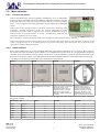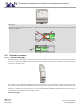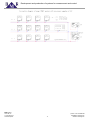
1
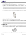
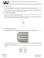
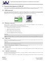
RNET heating system
IRC control system for hot-water heating
version 1.5
Development and production of systems for measurement and control
Content
1. General introduction and description....................................3
2.3.6. SJ64-8 switching module....................................9
2. Description...........................................................................4
3. The design and installation of the control system..............10
2.1. Description of parts......................................................4
4. Technical features...............................................................11
2.2. Main elements.............................................................5
5. Communication features of HC64_SZ................................12
2.2.1. Control unit HC64...............................................5
5.1. USB connection.........................................................12
2.2.2. Room sensors.....................................................5
5.2. Ethernet connection...................................................12
2.2.3. Actuator TSH24V................................................6
5.2.1. Web server........................................................12
2.2.4. Power supply unit SZ24V....................................6
5.2.2. Modbus TCP.....................................................12
2.3. Optional accessories...................................................7
5.2.3. Operation via the Internet.................................12
2.3.1. End item KC64_NET...........................................7
6. Connection diagram...........................................................14
2.3.2. LOW modem.......................................................8
7. Installation examples..........................................................15
2.3.3. Window contact...................................................8
7.1. Building with radiator heaters....................................15
2.3.4. Virtual sensor......................................................9
8. Sensor address ID setting..................................................17
2.3.5. SJ64-1 switching module....................................9
BMR trading
Horní lán 17
779 00 Olomouc
Czech Republic
2
phone: +420 778 066 566
[email protected]
www.bmr-trading.com
Development and production of systems for measurement and control
1. General introduction and description
Solving of the regulation system design can be divided into two parts:
• Heating source control.
• Heating control for particular rooms. System is based on so called IRC (Individual Room Control) regulation. IRC is
temperature control in every room according to time table set by user.
This installation manual provides information about IRC system design and installation.
BMR offers two IRC regulation systems:
• RNET regulation system. It is programmable control system for heating regulation of buildings with hot-water
radiators or floor and block storage heaters. In the maximal configuration it can contain 16 control section where every
control section controls up to 32 regulators. Whole system is able regulate temperature in 512 rooms.
• RT regulation system. It is programmable control system for heating regulation of buildings with direct electric
convectors, heating mattings and foils. In the maximal configuration it can contain 16 control section where every
control section controls up to 32 regulators. Whole system is able regulate temperature in 512 rooms.
Both systems are principally very similar. Used control station is the same, similar are thermostatic room sensors and optional
control software for PC. Systems are different only in control of heating source. For hot-water system RNET, thermostatic
sensors control thermo-drives on the radiators in the rooms, eventually ventilator for electric storage radiator. RT system
controls electric heating convectors or mattings by auxiliary power control unit. For switching of convectors or matting,
semiconductor switchers are used. Both systems can be combined together.
Main advantages:
• efficiency – up to 30 % energy saved
• comfort – heating is controlled absolutely automatically including the time changes summer/winter time
• easy setting and operation
• high reliability and working life. First installations are in the operation for more than 19 years
• 36 months warranty
• possibility to connect controllers into a system for large objects heating
• possibility to set and control system remotely by PC or any device with web browser
Great advantage of regulation systems RT and RNET is the method of the object heating control. Temperature in every room
can be programmed independently on the rest of the object. Mode can be the same for whole week or different for every day
in the week. Temperature is possible be changed eight times per day in the mode.
Room heating program for whole object can be turned to the low consumption mode (LOW program) manually or it can be
set by day and time. Normal mode is restored by the same way. This feature is very useful for longer planned absence from
building. For example when the family is leaving for the holiday and returning back to the comfortable heated house while
the house was kept on the low temperature during their absence.
Whole regulation system is modular and it is possible and easy to design it on the customer request and heating system
structure.
BMR trading
Horní lán 17
779 00 Olomouc
Czech Republic
3
phone: +420 778 066 566
[email protected]
www.bmr-trading.com
Development and production of systems for measurement and control
2. Description
RNET regulators can control heating at hot-water systems with radiators and also with heated floor. System RNET for hotwater system creates communication network, which connects all system components through.
Indoor thermostatic sensors for RNET system are not only passive temperature sensors, but they are based on intelligent
microprocessor control, which provides data and commands exchange with control section. This type of sensors is called
digital. Every single element of the system is identified by unique address defined by switches on the sensor. Other special
devices, for example end item, are identified by unique address defined by producer.
Within the regulation system RNET, every thermostatic sensor is counted as one control channel of the system. One control
unit can operate with maximum of 32 thermostatic sensors. One programmable thermostatic sensor can control up to 10
actuators TSH24V. This feature is very useful for schools, conference rooms, hospitals, etc.
2.1. Description of parts
Regulation system is based on elements, which can be defined as two following groups:
• Main elements. Basic elements are necessary for every regulator and neither one can be left out. Basis for the system is
control unit with power supply unit, programmable thermostat sensors and actuators.
• Additional elements. Additional elements increase comfort and improve some features of regulation system. However
their usage is not essential. In the group of additional elements there can be found:
• end-item KC64_NET
• window contact OK_NET
• LOW modem
• switching modules SJ64-1 and SJ64-8
BMR trading
Horní lán 17
779 00 Olomouc
Czech Republic
4
phone: +420 778 066 566
[email protected]
www.bmr-trading.com
Development and production of systems for measurement and control
2.2. Main elements
2.2.1.
Control unit HC64
Control unit HC64 keeps setting of regulation schedules for up to 32 independent
heating circuits. It is possible to set up to 8 different temperature changes in one day,
at any time and for any value. Part of the control unit delivery is also power supply
24 VAC / 2.5A. It supplies control unit, thermostatic sensors and actuators operated by
sensors.
Control unit has two operation modes. User mode, which allows displaying room
temperature, defining temperature profile, etc. Service (administrator) mode,
protected by password, which is supposed to be used for fundamental setting of
heating system, for example number of circuits, communication parameters and
temperature calibration for every sensor.
More information, operation and setting of HC64 can be found in technical documentation of HC64.
Control unit must be placed on common three-wires bus network to the place where the user will make all actions. If the
system is equipped by PC, it can be actually placed on any even invisible place. Personal computer can be connected to the
control unit via USB or Ethernet interface.
2.2.2.
Room sensors
Room sensors HTS64 range are in fact real digital thermostats with a built-in temperature sensor, output for direct control of
the actuator and input for window contact. HTS64 is an independent device that works as a PI (proportional integration)
controller which communicates with the control unit HC64 for to get the information about the targeted temperature in the
particular circuit. On the contrary it provides information about the measured temperature and actuator status to control unit.
According to a customer specification three types of thermostat can be offered:
HTS64
HTS64D
Basic type of thermostat.
HTS64DN
Thermostat with LCD which shows
current temperature and actuator
status.
HTS64DIN
Thermostat with LCD and buttons.
Display shows current temperature
and actuator status. Unit is
equipped with buttons for local
temperature setting. Locally set
temperature is kept until next
temperature change according to
the regime.
Thermostat designed for DIN rail
installation with a size of 1
standard module. Module has a
terminal for external analogue
temperature sensor and one 8A
output relay. ID address of the
HTS64DIN is set on the board
inside the instrument at the factory.
Sensors are available in several designs of case in order at to fit the style of the other elements used in the house. Following
designs are available.
Manufacturer / type
HTS64
HTS64D
HTS64DN
ABB
Element
●
●
●
ABB
Time
●
●
●
ABB
Tango
●
●
●
ABB
Neo
●
●
●
ABB
Neo Tech
●
●
●
ABB
Swing
●
●
●
ABB
Classic
●
●
●
BMR trading
Horní lán 17
779 00 Olomouc
Czech Republic
5
phone: +420 778 066 566
[email protected]
www.bmr-trading.com
Development and production of systems for measurement and control
Schneider
Unica Basic
●
●
●
Schneider
Unica Color
●
●
●
Schneider
Unica Top, Plus
●
●
●
Schneider
Marten M-Smart
●
●
●
Legrand
Cariva
●
●
●
Legrand
Valena
●
●
●
Legrand
Galea Life
●
Important
All sensors measure with accuracy 1ºC. This accuracy is absolutely sufficient for measurement of room temperature.
Nevertheless sensor can be calibrated on higher accuracy.
For heating systems with block storage heaters, their ventilator for 230 V AC is connected via external relay on terminals
labeled “valve”. Control voltage relay has to be 24 VDC. If relay is glimmering it is recommended to connect RC element (220
Ω + 470 μF/35V) on terminals of relay control voltage.
2.2.3.
Actuator TSH24V
Actuator is an unit which either opens or closes hot water inlet to the heater through the valve. Standard system design counts
with actuators with control voltage of 24 V DC. One actuator has consumption 33 mA at 24 V. One programmable thermostat
(sensor) can control up 10 actuators connected in parallel. Nevertheless total current demand has to be less than 500 mA.
Actuator TSH24V is delivered with supply lead of 0.5 m. In case that actuators from other producers are used in the system it
is necessary to count with higher drive current, which is passing for 30 seconds. Forgetting this can cause sensor transistor
output overloading and damage of sensor.
Actuator is designed for valves from: HEIMER, SIEMENS, HONEYWELL, HERZ, LANDYS. It is not possible to directly
use sockets from GIACOMINI and DANFOSS. These require reduction set.
Actuators for underfloor heaters are designed for 230 VAC control voltage.
Important
Actuator TSH24V is mechanically blocked in open position. Closing/opening is managed strictly by regulation and cannot be
operated manually. It is forbidden to rotate the actuator manually. It can caused damage of actuator and sensor as well.
Important
Actuator is not able, due to its construction, fully close the valve in case that ambient temperature is lower than 15°C.
If full closing of the valve is demanded at lower temperature the other type of actuator has to be chosen. For example it can
be pozistor actuator with working ambient temperature range 5°C … 40°C that is controlled via auxiliary relay with own
supply unit 24 VDC.
2.2.4.
Power supply unit SZ24V
Power supply unit 24 VDC / 2.5 A is designed for DIN rail mounting. It is used for supply of control sections, thermostats and
actuators. One unit can supply up to 50 pieces of actuators and in case of bigger systems there can be installed more power
supply units together. Power supply unit is a part of control unit HC64SZ delivery.
BMR trading
Horní lán 17
779 00 Olomouc
Czech Republic
6
phone: +420 778 066 566
[email protected]
www.bmr-trading.com
Development and production of systems for measurement and control
Important
If the power supply unit SZ24V is placed in the cabinet on a side of HC64 control unit, then it has to be on the right side of
the HC64 control unit.
2.3. Optional accessories
2.3.1.
End item KC64_NET
End item KC64_NET is designed to control heat source: boiler or heat pump. If the control section finds out that all actuators
are closed, it sends to the end item instruction for heat source shutdown. If at least one of actuator is open, end item gets
instruction to start heat source.
KC64_NET is very suitable for the regulation systems where the heat source is electric boiler, gas boiler or furnace oil boiler.
On the other hand, KC_NET is not suitable for hot-water storage systems and for all systems where at the boiler room level
the equithermic regulation or boiler cascade sorting is needed. Equithermic regulation is solved by BMR controller ETR16.
End item is connected to the same bus as the rest of system components. In the RNET64 heating system there can be up to 8
end items KC64_NET used for particular heating circuits.
Function description:
• If the heating system discovers that all heated zones reached target temperature, output relay of KC64_NET disconnect
BMR trading
Horní lán 17
779 00 Olomouc
Czech Republic
7
phone: +420 778 066 566
[email protected]
www.bmr-trading.com
Development and production of systems for measurement and control
and by that gives signal to heating source.
• Green LED On indicates supplied KC64_NET module.
• In the normal status (some of rooms are heated) the output relay contacts 15 – 16 are closed and yellow LED is On.
• If the KC64_NET receives command to disconnect heating source, output relay switch to connect contacts 15 – 18 and
yellow LED is Off.
Notice
KC64_NET response is not immediate. Command to disconnect or connect heating source is performed after regulation cycle
finish. According to the size of the RNET64 system the response time can be with several minute delay.
2.3.2.
LOW modem
LOW_MODEM allows in conjunction with GSM gate or telephone communicator, remotely switching the regulator over,
from comfortable heating mode to the saving mode (“LOW” mode) and back. By SMS messages, contact status of GSM gate
is controlled.
Description of function:
• Green LED on indicates module in the operation.
• Yellow LED off – terminals No. 4 – 5 closed, control section heats according to set mode.
• Yellow LED on – terminals No. 4 – 5 opened since GSM gate gives signal for control section and it switches to the LOW
mode.
Note
Low is connected to the system on the same bus as other items. Once the LOW_MODEM is installed into the system, it is
possible to control mode changes only by SMS GSM gate. Manual switching on control section is disabled. For enabling the
manual changes of LOW mod, power supply of LOW_MODEM must be disconnected.
2.3.3.
Window contact
Window contact OK_NET provides information about the window status (open/close) in the controlled room. It is connected
directly to the sensor and includes reed contact, which reacts on the closeness of the permanent magnet. Contact itself is
mounted on the window frame and magnet is fixed on the window. If the window is open, then programmable thermostat
disconnects appropriate circuit over the actuator and set 8ºC as a target temperature in the room.
If the room temperature drops below 8ºC, programmable thermostat opens actuators (protection against low temperature in
BMR trading
Horní lán 17
779 00 Olomouc
Czech Republic
8
phone: +420 778 066 566
[email protected]
www.bmr-trading.com
Development and production of systems for measurement and control
the room).
2.3.4.
Virtual sensor
Digital sensors HTS64 together with the control unit HC64 have special feature that allows to define so called “Virtual
sensor”. To the selected HTS64 sensors it is possible by software define virtual sensor with another ID address.
This virtual sensor behaves in the system as normal temperature sensor but with the difference that measured temperature is
from the mothers sensor. Thanks to this feature is possible by one temperature sensor HTS64 control the radiator in the
bathroom and by virtual sensor controls the underfloor heater in bathroom.
2.3.5.
SJ64-1 switching module
SJ64-1 is a switching module for DIN rail mounting. Module is listening the communication bus commands from selected
HTS64 sensor or virtual sensor and switch on/off the heater.
Module is connected to the same three wire bus as control unit and digital sensors. It is equipped by output relay contact
230V/16A. If the output contact is connected the yellow LED is on. In the system there can be several SJ64-1 modules with
the same ID address. Address changing of the module is described in the appendix.
2.3.6.
SJ64-8 switching module
Switching module SJ64-8 is very the same as SJ64-1 but with 8 relay outputs 230V/5A. Typical usage of SJ64-8 is for
underfloor heating actuators control in distributor board. Operation status of an outputs is signalized by LED.
In the RNET system there can be up to 4 SJ64-8 modules installed. Each output has a unique address related to the HTS64
sensor or virtual sensor. The address range has to be continual and maximally 8 addresses long. Programming of the outputs
addresses is done via control unit HC64.
In the RNET system the SJ64-8 module is identified by its own unique ID which can be adjusted on the front panel of the
module.
BMR trading
Horní lán 17
779 00 Olomouc
Czech Republic
9
phone: +420 778 066 566
[email protected]
www.bmr-trading.com
Development and production of systems for measurement and control
3. The design and installation of the control system
Installation of regulation system is easy and logical. If the operation steps are followed it should be without any complication
working on the first connection.
Design procedure:
1.
Investigate placement of all sensors, actuators and expected cable length of RNET network. These information are
essential for decision about the communication network topology. Cabling is done by three-wires line: power supply
24VDC (+), (-) and data line (L). Sensors are identified by unique ID number. Basic network topology is bus network. It
means that device are connected directly in parallel on the the three-wires bus. In case that particular conditions are
fulfilled, system allows to make modification for specific installation requirements. See connection diagrams at
appendix.
2.
Define number of actuators. This information is needed for power supply unit definition. If the total number of used
actuators is higher than 50 pieces, another power supply unit has to be installed.
3.
Define number of sensors. One control unit can operate up to 32 circuits (sensors). If the number of used sensors is
higher, than another control unit has to be used.
4.
Additional information. Requirements of end-item units, SJ64 units for control of underfloor heaters etc.
From above listed information, appropriate connection diagram is prepared. See connection diagram example at appendix.
Important
It is very important to design system with attention on minimization of power supply and communication length and
minimization of power loses on this line.
Considering the fact that one actuator has power consumption about 1.5 W, than while using more actuators, power load can
be high. Therefore during the designing process the cable diameter must be considered to assure that voltage drop at the line
end will be not more than 3 V.
For small systems with total number of used actuators less than 15 pieces, the cable diameter can be 0,8 mm 2. For larger
systems the cable diameter has to be at least 1.5 mm2.
Table of recommended cable types for three-wire line:
Number of TSH24V and cable length
Cable type
Note
< 15 units, cable circuit < 30 m
SYKY, SYKFY3x2x0.5
It is recommended to twist pair cables together and create three-wire
cable. Shielding is not connected.
< 25 units, cable circuit < 100 m
JYTY 3x1.0
Shielding not connected.
> 25 units, cable circuit max. 300 m
CYKY 3x1.5
Use auxiliary terminals in the thermostat.
Attention
In the system can be maximally 3 power line branches connected in parallel. Every parallel branch has some capacity, which
is counted together with other branches and complicates data transmission.
Connection of actuator TSH24V (24 V type) is most often realized by cable type SYKY 2x2x0.5 or any other two-wire cable
with similar minimum diameter. For connection of actuator (230 V type) is necessary to use cable for higher working voltage
and RCB protection.
At actuator location the connecting box must be installed. Inside this box the connection between cable from actuator (0.5 m
length) and cable from HTS64 air sensor is realized. If there is more actuators in the room, then all of them are connected in
parallel and to the sensor just one two-wire cable is brought. Maximum number of actuators connected to one thermostat is
10 actuators.
It is better to mechanically protect actuator against damage in special applications like, for example schools, sport clubs and
hotels. It is also recommended to move actuator to the position so they will be less visible.
Thermostats should be placed at the inner not cooled wall at level of standard light switch (150 cm above the ground).
Thermostats must not be placed to following position:
• Close to heat sources
• On the place with direct sunlight
BMR trading
Horní lán 17
779 00 Olomouc
Czech Republic
10
phone: +420 778 066 566
[email protected]
www.bmr-trading.com
Development and production of systems for measurement and control
• Behind the case, sofa or any other obstruction
• Under the ceiling
• Other places where temperature measurement affection is possible
Recommendation for installation:
• End item, if it is used, should be placed close to boiler or valve which will control
• Window contact is connected directly to the thermostat
• Control section may be placed according to customer request. For all application it is recommended to place control
section into the centre of cable network.
By observing all above listed rules, system installation will not be giving any complication and system will fully work on the
first start.
4. Technical features
Parameter
Value
Supply voltage
230 VAC / 24 VDC max. 2.5 A
Power consumption of control unit
0.3 VA
Power consumption of thermostat
0.2 VA
Power consumption of end item
0.2 VA
Power consumption of LOW modem
0.2 VA
Maximum number of independently controlled channels
32
Control voltage for actuators TSH24V
24 VDC
Maximum number of actuators TSH24V per one channel
10
Temperature measuring range
-10°C ... +50°C
Temperature measuring accuracy
1°C
Date and time backup
24 hours
Configuration backup
10 years
BMR trading
Horní lán 17
779 00 Olomouc
Czech Republic
11
phone: +420 778 066 566
[email protected]
www.bmr-trading.com
Development and production of systems for measurement and control
5. Communication features of HC64_SZ
Control unit HC64 is equipped by communication interfaces USB and Ethernet. For easy operation via USB or Ethernet
interface there is software tool called Heating Monitoring Software for PC operated by Windows xp and newer.
5.1. USB connection
Connection between HC64 control unit and PC is realized via standard USB port typ B. Communication is based on standard
HID (Human Interface Device) and there is no need for any signal converter or special drivers to be installed into the
operating system. For the connection the standard USB cable is used. The cable is a part of the delivery.
5.2. Ethernet connection
Ethernet interface is based on RJ45 port for connection of cable of type IPv4 10/100Mbit/s. Control unit HC64 has
implemented two fundamental network services on defined TCP ports.
For connection to the existing Ethernet it is necessary set following parameters:
1.
IP address. Factory setting is 192.168.1.113
2.
Mask. Factory setting is 255.255.255.000
3.
Gateway address. Factory setting is 0.0.0.0
4.
TCP port of web server. Factory setting is 80
5.
TCP port for Modbus TCP. Factory setting is 502
Important
HC64 does not support DHCP server. IP address of HC64 control unit has to be fixed and out of the DHCP server reserved
range.
5.2.1.
Web server
Web-server is a tool for most frequent control of heating system. Connection to the web page of HC64 control unit is via web
browser by entering the IP address of the control unit.
Important
Web browser has to support the HTML5 specification!
Access to the HC64 web-page is protected by user-name and password. Web-page does not have the service part which is
available only via Heating Monitoring Software or on the HC64 control unit.
5.2.2.
Modbus TCP
Modbus TCP interface is used for remote communication between Heating Monitoring Software (HMS) and control unit
HC64 via Ethernet.
5.2.3.
Operation via the Internet
For access of control unit HC64 from the Internet it is necessary establish so called IP forwarding on the router that is used
for connection of LAN to the Internet.
End user or installation company has to manage, together with an Internet provider, public IP address of router and then
BMR trading
Horní lán 17
779 00 Olomouc
Czech Republic
12
phone: +420 778 066 566
[email protected]
www.bmr-trading.com
Development and production of systems for measurement and control
forwarding of needed ports into LAN.
For successful access to the HC64 it is necessary do manage following things:
1.
Obtain the WAN IP address and TCP port of router which will be available from the Internet for HC64.
2.
Set the local IP address, mask, gateway, TCP port for web-server and TCP port for Modbus TCP.
3.
Set the IP forwarding of HC64 local IP address and TCP port to public IP
Detail description of the IT settings is not covered by this documentation. Setting has to be always done by authorized person
with knowledge of the IT system at the place of installation.
BMR trading
Horní lán 17
779 00 Olomouc
Czech Republic
13
phone: +420 778 066 566
[email protected]
www.bmr-trading.com
Development and production of systems for measurement and control
6. Connection diagram
BMR trading
Horní lán 17
779 00 Olomouc
Czech Republic
14
phone: +420 778 066 566
[email protected]
www.bmr-trading.com
Development and production of systems for measurement and control
7. Installation examples
7.1. Building with radiator heaters
BMR trading
Horní lán 17
779 00 Olomouc
Czech Republic
15
phone: +420 778 066 566
[email protected]
www.bmr-trading.com
Development and production of systems for measurement and control
BMR trading
Horní lán 17
779 00 Olomouc
Czech Republic
16
phone: +420 778 066 566
[email protected]
www.bmr-trading.com
Development and production of systems for measurement and control
8. Sensor address ID setting
Each digital sensors HTS64 and other element has to have its unique ID address in the communication bus. Addresses are set
via DIP switchers according following tables.
BMR trading
Horní lán 17
779 00 Olomouc
Czech Republic
17
phone: +420 778 066 566
[email protected]
www.bmr-trading.com